【0001】
【発明の属する技術分野】
この発明は、広角状態での撮像と望遠状態での撮像を受け付ける変倍光学装置に関するものである。
【0002】
【従来の技術】
撮像に用いられる光学系の役割は、被写体の光学像を像平面上に形成することである。被写体の光学像は、光電変換素子などにより電気信号に変換され、被写体画像信号として、記憶手段、処理手段、表示手段などに引き渡される。
より鮮明な画像を得るには、光学系の性能として十分な解像度特性が求められる。また、光を検出するには十分な光量で結像する必要がある。そのため、広い波長範囲の光を利用したり、開口径を大きくしたりする。広い波長範囲の光を利用するには、レンズ材料の屈折率の波長依存性に起因する収差を抑えなければならず、いわゆる「色消し」がなされた光学系が求められる。開口径を大きくするには、F値(レンズの焦点距離を絞りの直径で割ったもの)を小さくし、いわゆる「明るい」光学系であることが求められる。
【0003】
また、光学系には上記のような性能の他にも機能が求められる。その代表的なものが変倍機能である。遠い被写体の詳細を画像化する場合には、焦点距離を長くして望遠状態で撮像し、広い視野範囲を画像化する場合には、焦点距離を短くして広角状態で撮像する。
変倍機能を有する構成として、レンズの2群構成が知られており、例えば、以下の特許文献1に記載されている。このような2群構成の変倍光学装置はシンプルな構成であるという利点があるが、変倍比を大きくとれないことやF値を小さくできないなどの課題がある。
【0004】
2群構成の変倍光学装置と比べて、3群構成の変倍光学装置は、変倍比を大きくできて、F値が小さい明るい光学系が得られる。例えば、以下の特許文献2に記載されている光学系は、F値が2.8で、物体側から順に、均質媒質の単レンズ1枚のみからなる正の屈折力を有する第1レンズと、均質媒質の単レンズ1枚のみからなる負の屈折力を有する第2レンズと、均質媒質の単レンズ1枚のみからなる正の屈折力を有する第3レンズから構成されている。
変倍動作は、第2レンズと絞りと第3レンズとを光軸方向に個々別々の移動量で移動することにより、変倍比3.0(焦点距離4mm〜12mm)が得られる。変倍に際して、第1レンズの物体側面から像側面までの距離が不変であって37mmであり、望遠状態の焦点距離に対して3.1倍である。
【0005】
この光学系は、光軸上に形成される光学像のスポット径が20λ以上、軸外端のスポット径が40λ以上と非常に大きく、十分な解像度特性とは言えない。ここで、λは代表波長であり、特許文献2では0.587μmである。スポット径がこれ程までに大きくなる理由は、使用波長範囲(0.486μm〜0.656μm、代表波長0.587μmに対して約0.3倍の波長幅)において、光軸上の像位置が光軸方向に200λ以上も移動するためである。即ち、3群構成の変倍光学系は十分に色消しがなされておらず、その結果として十分な解像度特性が得られていないのである。
また、F値2.8は、十分な明るさとは言えず、特に被写体から発せられる微小な光エネルギーを捉える赤外線カメラには不十分である。
【0006】
【特許文献1】
特開2001−141998公報(第3頁から第4頁、図1)
【特許文献2】
特開2001−141996公報(第3頁から第4頁、図1)
【0007】
【発明が解決しようとする課題】
従来の変倍光学装置は以上のように構成されているので、2群構成と比べれば、変倍比を大きくできて、F値が小さい明るい光学系が得られる。しかし、3群構成のレンズの原料を特に考慮していないため、各レンズの屈折率が小さく(例えば、1.516,1.525)、かつ、分散能が大きく(例えば、0.156,0179)なり、その結果、十分に明るくて、色収差が小さい良好な解像度特性が得られないなどの課題があった。
【0008】
この発明は上記のような課題を解決するためになされたもので、広角状態であっても望遠状態であっても、明るく、かつ、良好な解像度特性が得られる変倍光学装置を得ることを目的とする。
【0009】
【課題を解決するための手段】
この発明に係る変倍光学装置は、正の屈折力を有する第1レンズと、負の屈折力を有する第2レンズと、正の屈折力を有する第3レンズとから光学系を構成して、第1、第2及び第3レンズの原料としてゲルマニウムを用いたものである。
【0010】
【発明の実施の形態】
以下、この発明の実施の一形態を説明する。
実施の形態1.
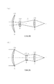
図1はこの発明の実施の形態1による変倍光学装置を示す構成図であり、図において、物体側に凸面が向けられている正メニスカスレンズ1は、原料がゲルマニウムGeから成る正の屈折力を有する第1レンズG1を構成している。正メニスカスレンズ1の像側において光軸方向に移動自在に設置されている両凹レンズ2は、原料がゲルマニウムGeから成る負の屈折力を有する第2レンズG2を構成している。両凹レンズ2は図示せぬ移動手段により設置位置が移動される。
【0011】
両凹レンズ2の像側に設置され、像側に凹面が向けられている正メニスカスレンズ3は、原料がゲルマニウムGeから成る正の屈折力を有する第3レンズG3を構成している。正メニスカスレンズ3は図示せぬ移動手段により設置位置が移動される。図中、Aは絞りを表し、Iは結像面を表している。
なお、この実施の形態1では、良好な解像度性能を得るため、正メニスカスレンズ1,3の像側面を非球面状に成形し、その他の面をすべて球面状に成形している。ただし、レンズの製造方法は成形に限るものではなく、研磨、研削、切削、エッチングなどであってもよい。
また、正メニスカスレンズ1,3の像側面ではなく、物体側面又は両面を非球面形状にしても良好な解像度性能を得ることができる。
【0012】
次に動作について説明する。
光学系を明るくするには開口径を大きくする必要がある。ザイデル収差と呼ばれるレンズで発生する収差は、球面収差が開口径の3乗に比例し、コマ収差が開口径の2乗に比例し、非点収差が開口径の1乗に比例することが知られている。このように、光学系を明るくしようとすると、それに伴って各レンズで発生する収差が増大するため、光学系全体としての収差を抑えて良好な解像度特性を得るのが困難になる。このことが変倍光学系の明るさを制限している理由である。
【0013】
一方、レンズで発生する収差は、レンズの屈折率と、レンズ間の中間媒質の屈折率との差が大きい程、小さくすることができることが知られている。多くの場合、中間媒質は空気であり、その屈折率は概略1に等しい。また、レンズ材料の屈折率は1以上の正の値である。従って、より屈折率が大きなレンズ材料を選択すれば、レンズで発生する収差を抑えることができる。
【0014】
ここで、上記の特許文献2の変倍光学系では、屈折率が小さなレンズ材料を使用しているため(屈折率が1.516と1.525のレンズ材料)、レンズで発生する収差を抑えることができず、F値が2.8に限られている。
これに対して、この実施の形態1では、高屈折率な物質であるゲルマニウムGeをレンズの原料にしているので、屈折率が4以上のレンズが得られる。その結果、レンズで発生する収差を抑えることができるため、F値が小さい明るい光学系を実現することができる。
【0015】
また、光学系の解像度特性を向上するためには色収差を抑制する必要があるが、上記の特許文献2の変倍光学系では、分散能が大きなレンズ材料を使用しているため(分散能が0.0156と0.0179のレンズ材料)、レンズで発生する色収差を抑えることができず、光軸上の像位置が光軸方向に200λ以上も移動する。そのため、光軸上に形成される光学像のスポット径が20λ以上、軸外端のスポット径が40λ以上と非常に大きくなっている。
これに対して、この実施の形態1では、低分散な物質であるゲルマニウムGeをレンズの原料にしているので、分散能が0.001以下のレンズが得られる。その結果、レンズで発生する色収差を抑えることができるため、良好な解像度特性の光学系を実現することができる。
【0016】
具体的には下記の通りである。
この実施の形態1では、F値が1.795であって、焦点距離が20〜100mmである変倍比5倍の変倍光学系を想定する。なお、望遠状態での半画角は1.7度であり、波長範囲は8.5μm〜11.5μmである。
広角状態と望遠状態の違いは、第2レンズG2である両凹レンズ2の位置であり、両凹レンズ2を光軸方向に移動することにより変倍機能が得られる。変倍に際して、最も大きな径を有する正メニスカスレンズ1、ならびに結像面Iに設置され電気配線が施された図示せぬ光電変換素子を固定としている。すなわち、正メニスカスレンズ1の物体側面から結像面Iまでの距離は不変であり、本実施例では165mmであり、望遠状態の焦点距離に対して約1.7倍である。
また、両凹レンズ2を光軸方向に移動することにより為される変倍に伴い発生するピントずれを補償するピント調整、ならびに有限距離の被写体に対するピント調整は、第3レンズG3である正メニスカスレンズ3を光軸方向に移動することにより為される。ただし、ピント調整は絞りAと第3レンズG3とを同時に移動して行ってもよい。
【0017】
ゲルマニウムGeの屈折率は、波長8.5μmで4.00454、波長10.0μmで4.00316、波長11.5μmで4.00245である。これより計算される分散能は0.00070であり、高屈折率で低分散な材料である。
このような材料をレンズ材料として選択することにより、変倍光学系における光軸上及び軸外端に形成される光学像のスポット径は、広角状態でそれぞれ0.9λ,1.8λ、望遠状態でそれぞれ1.4λ,1.8λと小さく、良好な解像度特性が得られる。ここで、λは代表波長であり、10μmである。使用波長範囲(8.5μm〜11.5μm、代表波長10μmに対して0.3倍の波長幅)において、光軸上の像位置の光軸方向の移動が広角状態で0.9λ、望遠状態で4.8λと抑えられている。
【0018】
以下、図1の変倍光学系の数値データを提示する。
非球面形状では、zを光の進行方向を正とする光軸とし、yを光軸と直交する方向にとると、下記の式にて表される。
z=1/(2×r)×y2+A4×y4+A6×y6+A8×y8
ただし、rは近軸曲率半径、A4、A6、A8はそれぞれ4次、6次、8次の非球面係数である。
【0019】
r1(正メニスカスレンズ1の物体側面の近軸曲率半径)=91.181
d1(正メニスカスレンズ1の物体側面と像側面の間隔)=3.462
r2(正メニスカスレンズ1の像側面の近軸曲率半径)=118.511
d2(正メニスカスレンズ1の像側面と両凹レンズ2の物体側面の間隔)
=54.288(広角状態),88.696(望遠状態)
r3(両凹レンズ2の物体側面の近軸曲率半径)=−140.746
d3(両凹レンズ2の物体側面と像側面の間隔)=2.000
r4(両凹レンズ2の像側面の近軸曲率半径)=99.112
d4(両凹レンズ2の像側面と絞りAの間隔)
=35.141(広角状態),0.734(望遠状態)
r5(絞りAの近軸曲率半径)=∞
d5(絞りAと正メニスカスレンズ3の物体側面の間隔)=33.007
r6(正メニスカスレンズ3の物体側面の近軸曲率半径)=52.023
d6(正メニスカスレンズ3の物体側面と像側面の間隔)=2.102
r7(正メニスカスレンズ3の像側面の近軸曲率半径)=151.267
d7(正メニスカスレンズ3の像側面と結像面Iの間隔)=34.805
【0020】
なお、正メニスカスレンズ1の像側面の非球面係数は、A4=7.611−08,A6=3.756e−12,A8=−1.225e−16であり、正メニスカスレンズ3の像側面の非球面係数は、A4=1.004e−6,A6=−1.719e−10,A8=1.179e−13である。
【0021】
以上で明らかなように、この実施の形態1によれば、正の屈折力を有する正メニスカスレンズ1と、負の屈折力を有する両凹レンズ2と、正の屈折力を有する正メニスカスレンズ3とから光学系を構成して、正メニスカスレンズ1,3及び両凹レンズ2の原料としてゲルマニウムGeを用いるように構成したので、広角状態であっても望遠状態であっても、明るく、かつ、良好な解像度特性が得られる効果を奏する。
【0022】
実施の形態2.
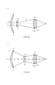
図2はこの発明の実施の形態2による変倍光学装置を示す構成図であり、図において、物体側に凸面が向けられている正メニスカスレンズ11は、原料がゲルマニウムGeから成る正の屈折力を有する第1レンズG1を構成している。正メニスカスレンズ11の像側において光軸方向に移動自在に設置されている両凹レンズ12は、原料がゲルマニウムGeから成る負の屈折力を有する第2レンズG2を構成している。両凹レンズ12は図示せぬ移動手段により設置位置が移動される。
【0023】
両凹レンズ12の像側に設置され、像側に凹面が向けられている正メニスカスレンズ13a(正屈折力レンズ)は、原料がゲルマニウムGeから成り、正の屈折力を有している。ただし、正メニスカスレンズ13aの代わりに両凸レンズを使用してもよい。負メニスカスレンズ13b(負屈折力レンズ)は、ゲルマニウムGeよりも分散能が大きな材料であるセレン化亜鉛ZnSeから成り、負の屈折力を有している。ただし、負メニスカスレンズ13bの代わりに両凹レンズを使用してもよい。なお、正メニスカスレンズ13a及び負メニスカスレンズ13bから正の屈折力を有する第3レンズG3を構成している。また、第3レンズG3は絞りAとともに図示せぬ移動手段により設置位置が移動される。
【0024】
この実施の形態2では、良好な解像度性能を得るため、正メニスカスレンズ11,13aの像側面を非球面状に成形し、その他の面をすべて球面状に成形している。ただし、レンズの製造方法は成形に限るものではなく、研磨、研削、切削、エッチングなどであってもよい。
また、正メニスカスレンズ11,13aの像側面ではなく、物体側面又は両面を非球面形状にしても良好な解像度性能を得ることができる。
【0025】
次に動作について説明する。
この実施の形態2では、F値が1.6であって、焦点距離が20〜100mmである変倍比5倍の変倍光学系を想定する。なお、望遠状態での半画角は1.7度であり、波長範囲は8.5μm〜11.5μmである。
広角状態と望遠状態の違いは、第2レンズG2ならびに第3レンズG3の位置である。両凹レンズ12を光軸方向に移動することにより変倍機能が得られる。変倍に際して、最も大きな径を有する正メニスカスレンズ11、ならびに結像面Iに設置された図示せぬ光電変換素子を固定としている。すなわち、正メニスカスレンズ11の物体側面から結像面Iまでの距離は不変であり、本実施例では130mmであり、望遠状態の焦点距離に対して1.3倍である。
また、両凹レンズ12を光軸方向に移動することにより為される変倍に伴い発生するピントずれを補償するピント調整、ならびに有限距離の被写体に対するピント調整は、絞りAと第3レンズG3とを光軸方向に移動することにより為される。ただし、絞りAを固定として、第3レンズG3のみを移動してもよい。
【0026】
負メニスカスレンズ13bの原料であるセレン化亜鉛ZnSeの屈折率は、波長8.5μmで2.41484、波長10.0μmで2.40652、波長11.5μmで2.39665であり、これより計算される分散能は0.0129である。第3レンズG3に負の屈折力を有する負メニスカスレンズ13bを加えることにより、負メニスカスレンズ13bで発生する色収差によって、正メニスカスレンズ13aで発生する残留色収差を抑制することができる。したがって、変倍光学系の色収差をさらに抑えて良好な解像度特性が得られる。
【0027】
このように、高屈折率で低分散なレンズ材料であるゲルマニウムGeと、このレンズ材料より分散能が大きなレンズ材料であるセレン化亜鉛ZnSeとを選択し、負メニスカスレンズ13bの屈折力を負に設定することにより、この変倍光学系における光軸上及び軸外端に形成される光学像のスポット径は、広角状態でそれぞれ0.7λ,1.9λ、望遠状態でそれぞれ1.0λ,2.7λと小さく、良好な解像度特性が得られる。使用波長範囲において、光軸上の像位置の光軸方向の移動が広角状態で1.5λ、望遠状態で3.5λと抑えられている。
【0028】
以下、図2の変倍光学系の数値データを提示する。
r1(正メニスカスレンズ11の物体側面の近軸曲率半径)=101.858
d1(正メニスカスレンズ11の物体側面と像側面の間隔)=3.724
r2(正メニスカスレンズ11の像側面の近軸曲率半径)=144.317
d2(正メニスカスレンズ11の像側面と両凹レンズ12の物体側面の間隔)=3.988(広角状態),74.495(望遠状態)
r3(両凹レンズ12の物体側面の近軸曲率半径)=−161.350
d3(両凹レンズ12の物体側面と像側面の間隔)=2.000
r4(両凹レンズ12の像側面の近軸曲率半径)=6113.504
d4(両凹レンズ12の像側面と絞りAの間隔)
=55.422(広角状態),0.507(望遠状態)
r5(絞りAの近軸曲率半径)=∞
d5(絞りAと正メニスカスレンズ13aの物体側面の間隔)=24.755
r6(正メニスカスレンズ13aの物体側面の近軸曲率半径)=56.202
d6(正メニスカスレンズ13aの物体側面と像側面の間隔)=2.000
r7(正メニスカスレンズ13aの像側面の近軸曲率半径)=198.694
d7(正メニスカスレンズ13aの像側面と負メニスカスレンズ13bの物体側面の間隔)=3.362
r8(負メニスカスレンズ13bの物体側面の近軸曲率半径)=−36.244
d8(負メニスカスレンズ13bの物体側面と像側面の間隔)=7.000
r9(負メニスカスレンズ13bの像側面の近軸曲率半径)=−39.507
d9(負メニスカスレンズ13bの像側面と結像面Iの間隔)
=28.114(広角状態),12.522(望遠状態)
【0029】
なお、正メニスカスレンズ11の像側面の非球面係数は、A4=4.050e−08,A6=1.242e−12,A8=−9.935e−17であり、正メニスカスレンズ13aの像側面の非球面係数は、A4=1.1302e−07,A6=8.299e−10,A8=−2.690e−12である。
【0030】
以上で明らかなように、この実施の形態2によれば、正の屈折力を有する正メニスカスレンズ11と、負の屈折力を有する両凹レンズ12と、正の屈折力を有する正メニスカスレンズ13a及び負の屈折力を有する負メニスカスレンズ13bとから光学系を構成して、正メニスカスレンズ11,13a及び両凹レンズ12の原料としてゲルマニウムGeを用い、負メニスカスレンズ13bの原料としてセレン化亜鉛ZnSeを用いるように構成したので、上記実施の形態1よりも明るく良好な解像度特性が得られる効果を奏する。
【0031】
なお、この実施の形態2では、負メニスカスレンズ13bの原料としてセレン化亜鉛ZnSeを用いるものについて示したが、ゲルマニウムGeよりも分散能が大きな材料であれば、セレン化亜鉛ZnSeに限るものではなく、例えば、半導体(ZnS,CdTe,GaAs)、アルカリ土類フロライド(CaF2,BaF2,MgF2)、アルカリハライド(NaCl,KCl)、カルコゲナイドガラスなどを用いてもよい。
【0032】
実施の形態3.
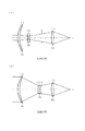
図3はこの発明の実施の形態3による変倍光学装置を示す構成図であり、図において、物体側に凸面が向けられている正メニスカスレンズ21は、原料がゲルマニウムGeから成る正の屈折力を有する第1レンズG1を構成している。正メニスカスレンズ21の像側に設置されている両凹レンズ22a(負屈折力レンズ)は、原料がゲルマニウムGeから成り、負の屈折力を有する。ただし、両凹レンズ22aの代わりに負メニスカスレンズを使用してもよい。両凹レンズ22aの像側に設置されている負メニスカスレンズ22b(負屈折力レンズ)は、ゲルマニウムGeよりも分散能が大きな材料であるセレン化亜鉛ZnSeから成り、負の屈折力を有している。ただし、負メニスカスレンズ22bの代わりに両凹レンズを使用してもよい。なお、両凹レンズ22a及び負メニスカスレンズ22bは第2レンズG2を構成している。第2レンズG2は図示せぬ移動手段により、光軸方向に移動自在に設置位置が移動される。
【0033】
負メニスカスレンズ22bの像側に設置され、像側に凹面が向けられている正メニスカスレンズ23は、原料がゲルマニウムGeから成る正の屈折力を有する第3レンズG3を構成している。正メニスカスレンズ23は絞りAとともに図示せぬ移動手段により設置位置が移動される。
この実施の形態3では、良好な解像度性能を得るため、正メニスカスレンズ21,23の像側面を非球面状に成形し、その他の面をすべて球面状に成形している。ただし、レンズの製造方法は成形に限るものではなく、研磨、研削、切削、エッチングなどであってもよい。
また、正メニスカスレンズ21,23の像側面ではなく、物体側面又は両面を非球面形状にしても良好な解像度性能を得ることができる。
【0034】
次に動作について説明する。
この実施の形態3では、F値が1.5であって、焦点距離が20〜100mmである変倍比5倍の変倍光学系を想定する。なお、望遠状態での半画角は1.7度であり、波長範囲は8.5μm〜11.5μmである。
広角状態と望遠状態の違いは、第2レンズG2ならびに第3レンズG3の位置である。第2レンズG2を光軸方向に移動することにより変倍機能が得られる。変倍に際して、最も大きな径を有する正メニスカスレンズ21、ならびに結像面Iに設置された図示せぬ光電変換素子を固定としている。すなわち、正メニスカスレンズ21の物体側面から結像面Iまでの距離は不変であり、本実施例では182mmであり、望遠状態の焦点距離に対して1.8倍である。
また、第2レンズG2を光軸方向に移動することにより為される変倍に伴い発生するピントずれを補償するピント調整、ならびに有限距離の被写体に対するピント調整は、絞りAと第3レンズG3である正メニスカスレンズ23とを光軸方向に移動することにより為される。ただし、絞りAを固定として、第3レンズG3のみを移動してもよい。
【0035】
第2レンズG2に負の屈折力を有する負メニスカスレンズ22bを加えることにより、負メニスカスレンズ22bで発生する色収差によって、両凹レンズ22aで発生する残留色収差を抑制することができる。したがって、変倍光学系の色収差をさらに抑えて良好な解像度特性が得られる。
このように、高屈折率で低分散なレンズ材料であるゲルマニウムGeと、このレンズ材料より分散能が大きなレンズ材料であるセレン化亜鉛ZnSeとを選択し、負メニスカスレンズ22bの屈折力を負に設定することにより、この変倍光学系における光軸上及び軸外端に形成される光学像のスポット径は、広角状態でそれぞれ1.1λ,2.7λ、望遠状態でそれぞれ0.7λ,1.6λと小さく、良好な解像度特性が得られる。使用波長範囲において、光軸上の像位置の光軸方向の移動が広角状態で1.2λ、望遠状態で1.6λと抑えられている。
【0036】
以下、図3の変倍光学系の数値データを提示する。
r1(正メニスカスレンズ21の物体側面の近軸曲率半径)=103.962
d1(正メニスカスレンズ21の物体側面と像側面の間隔)=3.309
r2(正メニスカスレンズ21の像側面の近軸曲率半径)=129.680
d2(正メニスカスレンズ21の像側面と両凹レンズ22aの物体側面の間隔)
=16.367(広角状態),100.147(望遠状態)
r3(両凹レンズ22aの物体側面の近軸曲率半径)=−325.533
d3(両凹レンズ22aの物体側面と像側面の間隔)=2.000
r4(両凹レンズ22aの像側面の近軸曲率半径)=444.845
d4(両凹レンズ22aの像側面と負メニスカスレンズ22bの物体側面の間隔)=2.653
r5(負メニスカスレンズ22bの物体側面の近軸曲率半径)=−40.343
d5(負メニスカスレンズ22bの物体側面と像側面の間隔)=2.341
r6(負メニスカスレンズ22bの像側面の近軸曲率半径)=−47.078
d6(負メニスカスレンズ22bの像側面と絞りAの間隔)
=78.817(広角状態),0.500(望遠状態)
r7(絞りAの近軸曲率半径)=∞
d7(絞りAと正メニスカスレンズ23の物体側面の間隔)=32.432
r8(正メニスカスレンズ23の物体側面の近軸曲率半径)=51.329
d8(正メニスカスレンズ23の物体側面と像側面の間隔)=2.081
r9(正メニスカスレンズ23の像側面の近軸曲率半径)=96.598
d9(正メニスカスレンズ23の像側面と結像面の間隔)
=41.893(広角状態),36.430(望遠状態)
【0037】
なお、正メニスカスレンズ21の像側面の非球面係数は、A4=5.750e−08 ,A6=1.529e−12,A8=6.464e−17であり、正メニスカスレンズ23の像側面の非球面係数は、A4=5.174e−7,A6=−3.969e−11,A8=1.248e−13である。
【0038】
以上で明らかなように、この実施の形態3によれば、正の屈折力を有する正メニスカスレンズ21と、負の屈折力を有する両凹レンズ22a及び負メニスカスレンズ22bと、正の屈折力を有する正メニスカスレンズ23とから光学系を構成して、正メニスカスレンズ21,23及び両凹レンズ22aの原料としてゲルマニウムGeを用い、負メニスカスレンズ22bの原料としてセレン化亜鉛ZnSeを用いるように構成したので、上記実施の形態1よりも明るく良好な解像度特性が得られる効果を奏する。
【0039】
なお、この実施の形態3では、負メニスカスレンズ22bの原料としてセレン化亜鉛ZnSeを用いるものについて示したが、ゲルマニウムGeよりも分散能が大きな材料であれば、セレン化亜鉛ZnSeに限るものではなく、例えば、半導体(ZnS,CdTe,GaAs)、アルカリ土類フロライド(CaF2,BaF2,MgF2)、アルカリハライド(NaCl,KCl)、カルコゲナイドガラスなどを用いてもよい。
【0040】
実施の形態4.
図4はこの発明の実施の形態4による変倍光学装置を示す構成図であり、図において、物体側に凸面が向けられている正メニスカスレンズ31は、原料がゲルマニウムGeから成る正の屈折力を有する第1レンズG1を構成している。正メニスカスレンズ31の像側において光軸方向に移動自在に設置されている両凹レンズ32は、原料がゲルマニウムGeから成る負の屈折力を有する第2レンズG2を構成している。両凹レンズ32は図示せぬ移動手段により設置位置が移動される。
両凹レンズ32の像側に設置され、像側に凹面が向けられている正メニスカスレンズ33は、原料がゲルマニウムGeから成る正の屈折力を有する第3レンズG3を構成している。正メニスカスレンズ33は絞りAとともに図示せぬ移動手段により設置位置が移動される。
【0041】
なお、この実施の形態4では、良好な解像度性能を得るため、正メニスカスレンズ31,33の像側面を非球面状に成形し、また、正メニスカスレンズ33の像側面に正の屈折力を有する焦点距離12345mmの回折光学素子を設けている。その他の面はすべて球面状に成形している。ただし、レンズの製造方法は成形に限るものではなく、研磨、研削、切削、エッチングなどであってもよい。
また、正メニスカスレンズ31,33の像側面ではなく、物体側面又は両面を非球面形状にしても良好な解像度性能を得ることができる。また、正メニスカスレンズ33の像側面ではなく、物体側面に回折光学素子を設けてもよいし、正メニスカスレンズ31又は両凹レンズ32の像側面又は物体側面に回折光学素子を設けてもよい。
【0042】
次に動作について説明する。
この実施の形態4では、F値が1.55であって、焦点距離が20〜100mmである変倍比5倍の変倍光学系を想定する。なお、望遠状態での半画角は1.7度であり、波長範囲は8.5μm〜11.5μmである。
広角状態と望遠状態の違いは、第2レンズG2である両凹レンズ32ならびに第3レンズG3のである正メニスカスレンズ33の位置である。両凹レンズ32を光軸方向に移動することにより変倍機能が得られる。最も大きな径を有する正メニスカスレンズ31、ならびに結像面Iに設置された図示せぬ光電変換素子を固定としている。本実施例では174mmであり、望遠状態の焦点距離に対して1.7倍である。
また、両凹レンズ32を光軸方向に移動することにより為される変倍に伴い発生するピントずれを補償するピント調整、ならびに有限距離の被写体に対するピント調整は、絞りAと正メニスカスレンズ33とを光軸方向に移動することにより為される。ただし、絞りAを固定として、正メニスカスレンズ33のみを移動してもよい。
【0043】
良く知られているように回折光学素子の分散能は負の値を有するので、第3レンズG3である正メニスカスレンズ33に、正の屈折力を有する回折光学素子を加えることにより、正メニスカスレンズ33で発生する残留色収差を抑制することができる。したがって、変倍光学系の色収差をさらに抑えて良好な解像度特性が得られる。
【0044】
このように、高屈折率で低分散なレンズ材料であるゲルマニウムGeを選択し、このレンズで発生する残留色収差を回折光学素子で打ち消すことにより、この変倍光学系における光軸上及び軸外端に形成される光学像のスポット径は、広角状態でそれぞれ0.9λ,3.0λ、望遠状態でそれぞれ1.3λ,2.1λと小さく、良好な解像度特性が得られる。使用波長範囲において、光軸上の像位置の光軸方向の移動が広角状態で2.3λ、望遠状態で3.6λと抑えられている。
【0045】
以下、図4の変倍光学系の数値データを提示する。
r1(正メニスカスレンズ31の物体側面の近軸曲率半径)=87.888
d1(正メニスカスレンズ31の物体側面と像側面の間隔)=3.601
r2(正メニスカスレンズ31の像側面の近軸曲率半径)=113.244
d2(正メニスカスレンズ31の像側面と両凹レンズ32の物体側面の間隔)=36.201(広角状態),79.176(望遠状態)
r3(両凹レンズ32の物体側面の近軸曲率半径)=−369.530
d3(両凹レンズ32の物体側面と像側面の間隔)=2.000
r4(両凹レンズ32の像側面の近軸曲率半径)=89.919
d4(両凹レンズ32の像側面と絞りAの間隔)
=44.240(広角状態),1.066(望遠状態)
r5(絞りAの近軸曲率半径)=∞
d5(絞りAと正メニスカスレンズ33の物体側面の間隔)=41.108
r6(正メニスカスレンズ33の物体側面の近軸曲率半径)=66.234
d6(正メニスカスレンズ33の物体側面と像側面の間隔)=2.850
r7(正メニスカスレンズ33の像側面の近軸曲率半径)=192.389
d7(正メニスカスレンズ33の像側面と結像面の間隔)
=44.403(広角状態),44.602(望遠状態)
【0046】
なお、正メニスカスレンズ31の像側面の非球面係数は、A4=8.663e−08,A6=3.682e−12,A8=7.390e−17であり、正メニスカスレンズ33の像側面の非球面係数は、A4=5.147E−07,A6=−1.298E−10,A8=1.284E−13である。
【0047】
以上で明らかなように、この実施の形態4によれば、正の屈折力を有する正メニスカスレンズ31と、負の屈折力を有する両凹レンズ32と、正の屈折力を有する正メニスカスレンズ33とから光学系を構成して、正メニスカスレンズ33の像側面に正の屈折力を有する回折光学素子を設けたので、上記実施の形態1よりも明るく良好な解像度特性が得られる効果を奏する。
【0048】
【発明の効果】
以上のように、この発明によれば、正の屈折力を有する第1レンズと、負の屈折力を有する第2レンズと、正の屈折力を有する第3レンズとから光学系を構成して、第1、第2及び第3レンズの原料としてゲルマニウムを用いるように構成したので、広角状態であっても望遠状態であっても、明るく、かつ、良好な解像度特性が得られる効果がある。
【図面の簡単な説明】
【図1】この発明の実施の形態1による変倍光学装置を示す構成図である。
【図2】この発明の実施の形態2による変倍光学装置を示す構成図である。
【図3】この発明の実施の形態3による変倍光学装置を示す構成図である。
【図4】この発明の実施の形態4による変倍光学装置を示す構成図である。
【符号の説明】
1 正メニスカスレンズ(第1レンズ)、2 両凹レンズ(第2レンズ)、3正メニスカスレンズ(第3レンズ)、11 正メニスカスレンズ(第1レンズ)、12 両凹レンズ(第2レンズ)、13a 正メニスカスレンズ(正屈折力レンズ、第3レンズ)、13b 負メニスカスレンズ(負屈折力レンズ、第3レンズ)、21 正メニスカスレンズ(第1レンズ)、22a 両凹レンズ(負屈折力レンズ、第2レンズ)、22b 負メニスカスレンズ(負屈折力レンズ、第2レンズ)、23 正メニスカスレンズ(第3レンズ)、31 正メニスカスレンズ(第1レンズ)、32 両凹レンズ(第2レンズ)、33 正メニスカスレンズ(第3レンズ)。[0001]
TECHNICAL FIELD OF THE INVENTION
The present invention relates to a variable power optical device that accepts imaging in a wide-angle state and imaging in a telephoto state.
[0002]
[Prior art]
The role of an optical system used for imaging is to form an optical image of a subject on an image plane. The optical image of the subject is converted into an electric signal by a photoelectric conversion element or the like, and is delivered to a storage unit, a processing unit, a display unit, or the like as a subject image signal.
In order to obtain a clearer image, a resolution characteristic sufficient for the performance of the optical system is required. Further, in order to detect light, it is necessary to form an image with a sufficient light amount. Therefore, light in a wide wavelength range is used or the aperture diameter is increased. In order to use light in a wide wavelength range, aberrations due to the wavelength dependence of the refractive index of the lens material must be suppressed, and an optical system that is so-called “achromatized” is required. In order to increase the aperture diameter, it is necessary to reduce the F value (the value obtained by dividing the focal length of the lens by the diameter of the stop) and to provide a so-called "bright" optical system.
[0003]
Further, the optical system is required to have functions in addition to the above-described performance. A typical example is a scaling function. When imaging a detail of a distant subject, imaging is performed in a telephoto state with a long focal length, and when imaging a wide viewing range, imaging is performed in a wide-angle state with a short focal length.
As a configuration having a zooming function, a two-group configuration of lenses is known, and is described, for example, in Patent Document 1 below. Such a two-unit variable-magnification optical device has the advantage of a simple configuration, but has problems such as a difficulty in increasing the zoom ratio and a reduction in the F-number.
[0004]
Compared with a variable power optical device having a two-group configuration, a variable power optical device having a three-group configuration can increase the variable power ratio and obtain a bright optical system having a small F value. For example, an optical system described in Patent Literature 2 below has a first lens having an F value of 2.8 and having, in order from the object side, having only one single lens of a homogeneous medium and having a positive refractive power, It comprises a second lens having only one single lens of a homogeneous medium and having a negative refractive power, and a third lens having only one single lens of a homogeneous medium and having a positive refractive power.
In the variable power operation, a variable power ratio of 3.0 (focal length of 4 mm to 12 mm) is obtained by moving the second lens, the diaphragm, and the third lens in the optical axis direction by separate moving amounts. At the time of zooming, the distance from the object side surface to the image side surface of the first lens is unchanged and is 37 mm, which is 3.1 times the focal length in the telephoto state.
[0005]
This optical system has a very large spot diameter of an optical image formed on the optical axis of 20λ or more, and a spot diameter of an off-axis end of 40λ or more, which is not sufficient resolution characteristics. Here, λ is a representative wavelength, and in Patent Document 2, it is 0.587 μm. The reason why the spot diameter becomes so large is that in the working wavelength range (0.486 μm to 0.656 μm, a wavelength width approximately 0.3 times the representative wavelength 0.587 μm), the image position on the optical axis is This is because it moves more than 200λ in the axial direction. That is, the three-unit variable magnification optical system is not sufficiently achromatized, and as a result, sufficient resolution characteristics are not obtained.
Further, an F value of 2.8 cannot be said to be sufficient brightness, and is insufficient particularly for an infrared camera that captures minute light energy emitted from a subject.
[0006]
[Patent Document 1]
JP 2001-141998 (Pages 3 to 4, FIG. 1)
[Patent Document 2]
JP 2001-141996 (pages 3 to 4, FIG. 1)
[0007]
[Problems to be solved by the invention]
Since the conventional variable power optical device is configured as described above, the variable power ratio can be increased and a bright optical system with a small F value can be obtained as compared with the two-unit configuration. However, since the raw materials of the three-group lens are not particularly considered, the refractive index of each lens is small (for example, 1.516, 1.525) and the dispersing power is large (for example, 0.156,0179). As a result, there is a problem that a satisfactory resolution characteristic with sufficient brightness and small chromatic aberration cannot be obtained.
[0008]
The present invention has been made in order to solve the above-described problems, and it is an object of the present invention to provide a variable power optical device that is bright even in a wide-angle state or a telephoto state, and that can obtain good resolution characteristics. Aim.
[0009]
[Means for Solving the Problems]
The variable power optical apparatus according to the present invention comprises an optical system including a first lens having a positive refractive power, a second lens having a negative refractive power, and a third lens having a positive refractive power, Germanium is used as a raw material for the first, second and third lenses.
[0010]
BEST MODE FOR CARRYING OUT THE INVENTION
Hereinafter, an embodiment of the present invention will be described.
Embodiment 1 FIG.
FIG. 1 is a configuration diagram showing a variable power optical apparatus according to Embodiment 1 of the present invention. In the figure, a positive meniscus lens 1 having a convex surface facing the object side has a positive refractive power made of germanium Ge. And a first lens G1 having the following configuration. The biconcave lens 2 movably installed in the optical axis direction on the image side of the positive meniscus lens 1 forms a second lens G2 having a negative refractive power and made of germanium Ge. The installation position of the biconcave lens 2 is moved by moving means (not shown).
[0011]
The positive meniscus lens 3 which is provided on the image side of the biconcave lens 2 and has a concave surface facing the image side constitutes a third lens G3 having a positive refractive power and made of germanium Ge. The installation position of the positive meniscus lens 3 is moved by moving means (not shown). In the figure, A represents the stop, and I represents the image plane.
In the first embodiment, in order to obtain good resolution performance, the image side surfaces of the positive meniscus lenses 1 and 3 are formed in an aspherical shape, and all other surfaces are formed in a spherical shape. However, the method of manufacturing the lens is not limited to molding, but may be polishing, grinding, cutting, etching, or the like.
Also, good resolution performance can be obtained even if the object side surface or both surfaces, instead of the image side surfaces of the positive meniscus lenses 1 and 3, are aspherical.
[0012]
Next, the operation will be described.
In order to brighten the optical system, it is necessary to increase the aperture diameter. The aberrations that occur in a lens called Seidel aberration are known to be such that spherical aberration is proportional to the cube of the aperture diameter, coma is proportional to the square of the aperture diameter, and astigmatism is proportional to the first power of the aperture diameter. Have been. As described above, when an attempt is made to brighten the optical system, aberrations generated in the respective lenses increase accordingly, and it becomes difficult to suppress aberrations of the entire optical system and obtain good resolution characteristics. This is the reason for limiting the brightness of the variable power optical system.
[0013]
On the other hand, it is known that the aberration generated in the lens can be reduced as the difference between the refractive index of the lens and the refractive index of the intermediate medium between the lenses is larger. In most cases, the intermediate medium is air, whose refractive index is approximately equal to one. The refractive index of the lens material is a positive value of 1 or more. Therefore, if a lens material having a larger refractive index is selected, aberrations generated in the lens can be suppressed.
[0014]
Here, in the variable power optical system of Patent Document 2 described above, since a lens material having a small refractive index is used (a lens material having a refractive index of 1.516 and 1.525), aberration generated in the lens is suppressed. And the F-number is limited to 2.8.
On the other hand, in the first embodiment, germanium Ge, which is a substance having a high refractive index, is used as a material of the lens, so that a lens having a refractive index of 4 or more can be obtained. As a result, aberration generated in the lens can be suppressed, and a bright optical system with a small F value can be realized.
[0015]
Further, in order to improve the resolution characteristics of the optical system, it is necessary to suppress chromatic aberration. However, in the variable magnification optical system of Patent Document 2 described above, a lens material having a large dispersing power is used (the dispersing power is low). However, the chromatic aberration generated in the lens cannot be suppressed, and the image position on the optical axis moves by 200λ or more in the optical axis direction. Therefore, the spot diameter of the optical image formed on the optical axis is as large as 20λ or more, and the spot diameter at the off-axis end is as large as 40λ or more.
On the other hand, in the first embodiment, germanium Ge, which is a low-dispersion substance, is used as a raw material of the lens, so that a lens having a dispersibility of 0.001 or less can be obtained. As a result, chromatic aberration generated in the lens can be suppressed, and an optical system with good resolution characteristics can be realized.
[0016]
Specifically, it is as follows.
In the first embodiment, a variable power optical system having an F value of 1.795 and a focal length of 20 to 100 mm and a variable power ratio of 5 is assumed. The half angle of view in the telephoto state is 1.7 degrees, and the wavelength range is 8.5 μm to 11.5 μm.
The difference between the wide-angle state and the telephoto state is the position of the biconcave lens 2 that is the second lens G2, and the zoom function is obtained by moving the biconcave lens 2 in the optical axis direction. At the time of zooming, the positive meniscus lens 1 having the largest diameter and the photoelectric conversion element (not shown) provided on the imaging plane I and provided with electric wiring are fixed. That is, the distance from the object side surface of the positive meniscus lens 1 to the imaging plane I is invariable, is 165 mm in this embodiment, and is about 1.7 times the focal length in the telephoto state.
Further, the focus adjustment for compensating for a focus shift caused by zooming caused by moving the biconcave lens 2 in the optical axis direction and the focus adjustment for a subject at a finite distance are performed by the positive meniscus lens as the third lens G3. 3 in the optical axis direction. However, the focus adjustment may be performed by simultaneously moving the aperture A and the third lens G3.
[0017]
The refractive index of germanium Ge is 4.00045 at a wavelength of 8.5 μm, 4.0316 at a wavelength of 10.0 μm, and 4.0245 at a wavelength of 11.5 μm. The dispersing power calculated from this is 0.00070, and the material has a high refractive index and low dispersion.
By selecting such a material as the lens material, the spot diameters of the optical images formed on the optical axis and at the off-axis end in the variable power optical system are 0.9λ and 1.8λ in the wide-angle state and the telephoto state, respectively. , Respectively, which are as small as 1.4λ and 1.8λ, respectively, and a good resolution characteristic can be obtained. Here, λ is a representative wavelength, which is 10 μm. In the operating wavelength range (8.5 μm to 11.5 μm, a wavelength width of 0.3 times the representative wavelength of 10 μm), the movement of the image position on the optical axis in the optical axis direction is 0.9λ in a wide-angle state, and a telephoto state. At 4.8λ.
[0018]
Hereinafter, numerical data of the variable power optical system of FIG. 1 will be presented.
In the aspherical shape, when z is an optical axis whose light traveling direction is positive and y is a direction orthogonal to the optical axis, it is expressed by the following equation.
z = 1 / (2 × r) × y2+ A4xy4+ A6xy6+ A8 × y8
Here, r is a paraxial radius of curvature, and A4, A6, and A8 are fourth-order, sixth-order, and eighth-order aspherical coefficients, respectively.
[0019]
r1 (paraxial radius of curvature of the object side surface of the positive meniscus lens 1) = 91.181
d1 (the distance between the object side surface and the image side surface of the positive meniscus lens 1) = 3.462
r2 (paraxial radius of curvature of the image side surface of the positive meniscus lens 1) = 1118.511
d2 (the distance between the image side surface of the positive meniscus lens 1 and the object side surface of the biconcave lens 2)
= 54.288 (wide-angle state), 88.696 (telephoto state)
r3 (paraxial radius of curvature of the object side surface of the biconcave lens 2) = − 140.746
d3 (the distance between the object side surface and the image side surface of the biconcave lens 2) = 2.000
r4 (paraxial radius of curvature of the image side surface of the biconcave lens 2) = 99.112
d4 (the distance between the image side surface of the biconcave lens 2 and the diaphragm A)
= 35.141 (wide-angle state), 0.734 (telephoto state)
r5 (paraxial radius of curvature of aperture A) = ∞
d5 (the distance between the stop A and the object side surface of the positive meniscus lens 3) = 33.007
r6 (paraxial radius of curvature of the object side surface of the positive meniscus lens 3) = 52.023
d6 (the distance between the object side surface and the image side surface of the positive meniscus lens 3) = 2.102
r7 (paraxial radius of curvature of the image side surface of the positive meniscus lens 3) = 151.267
d7 (the distance between the image side surface of the positive meniscus lens 3 and the image plane I) = 34.805
[0020]
The aspherical surface coefficient of the image side surface of the positive meniscus lens 1 is A4 = 7.611-08, A6 = 3.756e-12, A8 = -1.225e-16. The aspheric coefficients are A4 = 1.004e-6, A6 = -1.719e-10, and A8 = 1.179e-13.
[0021]
As is clear from the above, according to the first embodiment, the positive meniscus lens 1 having a positive refractive power, the biconcave lens 2 having a negative refractive power, and the positive meniscus lens 3 having a positive refractive power , And germanium Ge is used as a raw material for the positive meniscus lenses 1 and 3 and the biconcave lens 2, so that it is bright and excellent even in a wide-angle state or a telephoto state. This produces an effect of obtaining resolution characteristics.
[0022]
Embodiment 2 FIG.
FIG. 2 is a configuration diagram showing a variable power optical apparatus according to Embodiment 2 of the present invention. In the figure, a positive meniscus lens 11 having a convex surface facing the object side has a positive refractive power made of germanium Ge. And a first lens G1 having the following configuration. The biconcave lens 12 movably installed in the optical axis direction on the image side of the positive meniscus lens 11 constitutes a second lens G2 having a negative refractive power and made of germanium Ge. The installation position of the biconcave lens 12 is moved by moving means (not shown).
[0023]
The positive meniscus lens 13a (positive refractive power lens) which is provided on the image side of the biconcave lens 12 and has a concave surface facing the image side is made of germanium Ge, and has a positive refractive power. However, a biconvex lens may be used instead of the positive meniscus lens 13a. The negative meniscus lens 13b (negative refractive power lens) is made of zinc selenide ZnSe, which is a material having a larger dispersing power than germanium Ge, and has a negative refractive power. However, a biconcave lens may be used instead of the negative meniscus lens 13b. The positive meniscus lens 13a and the negative meniscus lens 13b constitute a third lens G3 having a positive refractive power. The installation position of the third lens G3 is moved by the moving means (not shown) together with the stop A.
[0024]
In the second embodiment, in order to obtain good resolution performance, the image side surfaces of the positive meniscus lenses 11 and 13a are formed to be aspherical, and all other surfaces are formed to be spherical. However, the method of manufacturing the lens is not limited to molding, but may be polishing, grinding, cutting, etching, or the like.
In addition, good resolution performance can be obtained even if the object side surface or both surfaces, instead of the image side surfaces of the positive meniscus lenses 11, 13a, are aspherical.
[0025]
Next, the operation will be described.
In the second embodiment, a variable power optical system having an F value of 1.6 and a focal length of 20 to 100 mm and a variable power ratio of 5 is assumed. The half angle of view in the telephoto state is 1.7 degrees, and the wavelength range is 8.5 μm to 11.5 μm.
The difference between the wide-angle state and the telephoto state is the position of the second lens G2 and the third lens G3. By moving the biconcave lens 12 in the optical axis direction, a zooming function can be obtained. At the time of zooming, the positive meniscus lens 11 having the largest diameter and the photoelectric conversion element (not shown) provided on the image plane I are fixed. That is, the distance from the object side surface of the positive meniscus lens 11 to the imaging plane I is invariable, is 130 mm in this embodiment, and is 1.3 times the focal length in the telephoto state.
Focus adjustment for compensating for a focus shift caused by zooming caused by moving the biconcave lens 12 in the optical axis direction and focus adjustment for a subject at a finite distance are performed by stopping the stop A and the third lens G3. This is performed by moving in the optical axis direction. However, the stop A may be fixed and only the third lens G3 may be moved.
[0026]
The refractive index of zinc selenide ZnSe, which is a raw material of the negative meniscus lens 13b, is 2.44844 at a wavelength of 8.5 μm, 2.40652 at a wavelength of 10.0 μm, and 2.39665 at a wavelength of 11.5 μm. The dispersing power is 0.0129. By adding the negative meniscus lens 13b having a negative refractive power to the third lens G3, residual chromatic aberration generated in the positive meniscus lens 13a can be suppressed by chromatic aberration generated in the negative meniscus lens 13b. Therefore, good resolution characteristics can be obtained by further suppressing chromatic aberration of the variable power optical system.
[0027]
As described above, germanium Ge, which is a lens material having a high refractive index and low dispersion, and zinc selenide ZnSe, which is a lens material having a larger dispersing power than this lens material, are selected to make the refractive power of the negative meniscus lens 13b negative. By setting, the spot diameter of the optical image formed on the optical axis and at the off-axis end in the variable power optical system is 0.7λ, 1.9λ in the wide angle state, and 1.0λ, 2 in the telephoto state, respectively. .7λ, and good resolution characteristics can be obtained. In the operating wavelength range, the movement of the image position on the optical axis in the optical axis direction is suppressed to 1.5λ in the wide angle state and 3.5λ in the telephoto state.
[0028]
Hereinafter, numerical data of the variable power optical system of FIG. 2 will be presented.
r1 (paraxial radius of curvature of the object side surface of the positive meniscus lens 11) = 101.858
d1 (the distance between the object side surface and the image side surface of the positive meniscus lens 11) = 3.724
r2 (paraxial radius of curvature of the image side surface of the positive meniscus lens 11) = 144.317
d2 (the distance between the image side surface of the positive meniscus lens 11 and the object side surface of the biconcave lens 12) = 3.988 (wide-angle state), 74.495 (telephoto state)
r3 (paraxial radius of curvature of the object side surface of the biconcave lens 12) = − 161.350
d3 (the distance between the object side surface and the image side surface of the biconcave lens 12) = 2.000
r4 (paraxial radius of curvature of the image side surface of the biconcave lens 12) = 6113.504
d4 (the distance between the image side surface of the biconcave lens 12 and the stop A)
= 55.422 (wide-angle state), 0.507 (telephoto state)
r5 (paraxial radius of curvature of aperture A) = ∞
d5 (the distance between the diaphragm A and the object side surface of the positive meniscus lens 13a) = 24.755
r6 (paraxial radius of curvature of the object side surface of the positive meniscus lens 13a) = 56.202
d6 (the distance between the object side surface and the image side surface of the positive meniscus lens 13a) = 2.000
r7 (paraxial radius of curvature of the image side surface of the positive meniscus lens 13a) = 198.694
d7 (the distance between the image side surface of the positive meniscus lens 13a and the object side surface of the negative meniscus lens 13b) = 3.362
r8 (paraxial radius of curvature of the object side surface of the negative meniscus lens 13b) = − 36.244
d8 (the distance between the object side surface and the image side surface of the negative meniscus lens 13b) = 7.000
r9 (paraxial radius of curvature of the image side surface of the negative meniscus lens 13b) = − 39.507
d9 (the distance between the image side surface of the negative meniscus lens 13b and the image plane I)
= 28.114 (wide-angle state), 12.522 (telephoto state)
[0029]
Note that the aspherical surface coefficients of the image side surface of the positive meniscus lens 11 are A4 = 4.050e-08, A6 = 1.242e-12, A8 = -9.935e-17, and the image side surface of the positive meniscus lens 13a. The aspherical coefficients are A4 = 1.130e-07, A6 = 8.299e-10, and A8 = -2.690e-12.
[0030]
As is clear from the above, according to the second embodiment, the positive meniscus lens 11 having a positive refractive power, the biconcave lens 12 having a negative refractive power, the positive meniscus lens 13a having a positive refractive power, An optical system is constituted by the negative meniscus lens 13b having a negative refractive power, and germanium Ge is used as a raw material of the positive meniscus lenses 11, 13a and the biconcave lens 12, and zinc selenide ZnSe is used as a raw material of the negative meniscus lens 13b. With such a configuration, an effect of obtaining a brighter and better resolution characteristic than in the first embodiment can be obtained.
[0031]
In the second embodiment, the case where zinc selenide ZnSe is used as a raw material of the negative meniscus lens 13b has been described. However, as long as the material has a larger dispersibility than germanium Ge, the material is not limited to zinc selenide ZnSe. For example, semiconductors (ZnS, CdTe, GaAs), alkaline earth fluorides (CaF2, BaF2, MgF2), alkali halides (NaCl, KCl), and chalcogenide glass may be used.
[0032]
Embodiment 3 FIG.
FIG. 3 is a block diagram showing a variable power optical apparatus according to Embodiment 3 of the present invention. In the figure, a positive meniscus lens 21 having a convex surface facing the object side has a positive refractive power made of germanium Ge. The first lens G1 having the following configuration. The biconcave lens 22a (negative refractive power lens) provided on the image side of the positive meniscus lens 21 is made of germanium Ge and has a negative refractive power. However, a negative meniscus lens may be used instead of the biconcave lens 22a. The negative meniscus lens 22b (negative refractive power lens) provided on the image side of the biconcave lens 22a is made of zinc selenide ZnSe, which is a material having a larger dispersing power than germanium Ge, and has a negative refractive power. . However, a biconcave lens may be used instead of the negative meniscus lens 22b. Note that the biconcave lens 22a and the negative meniscus lens 22b constitute a second lens G2. The setting position of the second lens G2 is movably moved in the optical axis direction by moving means (not shown).
[0033]
The positive meniscus lens 23, which is provided on the image side of the negative meniscus lens 22b and has a concave surface facing the image side, forms a third lens G3 having a positive refractive power and made of germanium Ge. The installation position of the positive meniscus lens 23 is moved together with the diaphragm A by moving means (not shown).
In the third embodiment, in order to obtain good resolution performance, the image side surfaces of the positive meniscus lenses 21 and 23 are formed to be aspherical, and all other surfaces are formed to be spherical. However, the method of manufacturing the lens is not limited to molding, but may be polishing, grinding, cutting, etching, or the like.
In addition, good resolution performance can be obtained even if the object side surface or both surfaces, instead of the image side surfaces of the positive meniscus lenses 21 and 23, are aspherical.
[0034]
Next, the operation will be described.
In the third embodiment, a variable power optical system having an F-number of 1.5 and a focal length of 20 to 100 mm and a variable power ratio of 5 is assumed. The half angle of view in the telephoto state is 1.7 degrees, and the wavelength range is 8.5 μm to 11.5 μm.
The difference between the wide-angle state and the telephoto state is the position of the second lens G2 and the third lens G3. By moving the second lens G2 in the optical axis direction, a zooming function can be obtained. At the time of zooming, the positive meniscus lens 21 having the largest diameter and the photoelectric conversion element (not shown) installed on the image plane I are fixed. That is, the distance from the object side surface of the positive meniscus lens 21 to the imaging plane I is invariable, is 182 mm in the present embodiment, and is 1.8 times the focal length in the telephoto state.
Further, focus adjustment for compensating for a focus shift caused by zooming performed by moving the second lens G2 in the optical axis direction and focus adjustment for a subject at a finite distance are performed by the aperture A and the third lens G3. This is performed by moving a certain positive meniscus lens 23 in the optical axis direction. However, the stop A may be fixed and only the third lens G3 may be moved.
[0035]
By adding the negative meniscus lens 22b having a negative refractive power to the second lens G2, residual chromatic aberration generated in the biconcave lens 22a can be suppressed by chromatic aberration generated in the negative meniscus lens 22b. Therefore, good resolution characteristics can be obtained by further suppressing chromatic aberration of the variable power optical system.
In this manner, germanium Ge, which is a lens material having a high refractive index and low dispersion, and zinc selenide ZnSe, which is a lens material having a larger dispersing power than this lens material, are selected to make the refractive power of the negative meniscus lens 22b negative. By setting, the spot diameter of the optical image formed on the optical axis and at the off-axis end in this variable power optical system is 1.1λ and 2.7λ in the wide-angle state, and 0.7λ and 1λ in the telephoto state, respectively. .6λ, and good resolution characteristics can be obtained. In the operating wavelength range, the movement of the image position on the optical axis in the optical axis direction is suppressed to 1.2λ in the wide-angle state and 1.6λ in the telephoto state.
[0036]
Hereinafter, numerical data of the variable power optical system of FIG. 3 will be presented.
r1 (paraxial radius of curvature of the object side surface of the positive meniscus lens 21) = 103.962
d1 (the distance between the object side surface and the image side surface of the positive meniscus lens 21) = 3.309
r2 (paraxial radius of curvature of the image side surface of the positive meniscus lens 21) = 129.680
d2 (the distance between the image side surface of the positive meniscus lens 21 and the object side surface of the biconcave lens 22a)
= 16.367 (wide-angle state), 100.147 (telephoto state)
r3 (paraxial radius of curvature of the object side surface of the biconcave lens 22a) = − 325.533
d3 (the distance between the object side surface and the image side surface of the biconcave lens 22a) = 2.000
r4 (paraxial radius of curvature of the image side surface of the biconcave lens 22a) = 444.845
d4 (the distance between the image side surface of the biconcave lens 22a and the object side surface of the negative meniscus lens 22b) = 2.653
r5 (paraxial radius of curvature of the object side surface of the negative meniscus lens 22b) = − 40.343
d5 (the distance between the object side surface and the image side surface of the negative meniscus lens 22b) = 2.341
r6 (paraxial radius of curvature of the image side surface of the negative meniscus lens 22b) = − 47.078
d6 (the distance between the image side surface of the negative meniscus lens 22b and the diaphragm A)
= 78.817 (wide-angle state), 0.500 (telephoto state)
r7 (paraxial radius of curvature of aperture A) = ∞
d7 (the distance between the aperture A and the object side surface of the positive meniscus lens 23) = 32.432
r8 (paraxial radius of curvature of the object side surface of the positive meniscus lens 23) = 51.329
d8 (the distance between the object side surface and the image side surface of the positive meniscus lens 23) = 2.081
r9 (paraxial radius of curvature of the image side surface of the positive meniscus lens 23) = 96.598
d9 (the distance between the image side surface and the image forming surface of the positive meniscus lens 23)
= 41.893 (wide-angle state), 36.430 (telephoto state)
[0037]
The aspherical surface coefficients of the image side surface of the positive meniscus lens 21 are A4 = 5.750e-08, A6 = 1.529e-12, A8 = 6.464e-17, and the non-spherical surface of the image side surface of the positive meniscus lens 23 is non-uniform. The spherical coefficients are A4 = 5.174e-7, A6 = -3.969e-11, A8 = 1.248e-13.
[0038]
As apparent from the above, according to the third embodiment, the positive meniscus lens 21 having a positive refractive power, the biconcave lens 22a and the negative meniscus lens 22b having a negative refractive power, and the positive meniscus lens 22b having a positive refractive power. Since the optical system is configured from the positive meniscus lens 23, germanium Ge is used as a raw material of the positive meniscus lenses 21, 23 and the biconcave lens 22a, and zinc selenide ZnSe is used as a raw material of the negative meniscus lens 22b. There is an effect that brighter and better resolution characteristics can be obtained than in the first embodiment.
[0039]
In the third embodiment, the case where zinc selenide ZnSe is used as a raw material of the negative meniscus lens 22b has been described. However, as long as the material has a larger dispersibility than germanium Ge, the material is not limited to zinc selenide ZnSe. For example, semiconductors (ZnS, CdTe, GaAs), alkaline earth fluorides (CaF2, BaF2, MgF2), alkali halides (NaCl, KCl), and chalcogenide glass may be used.
[0040]
Embodiment 4 FIG.
FIG. 4 is a configuration diagram showing a variable power optical apparatus according to Embodiment 4 of the present invention. In the drawing, a positive meniscus lens 31 having a convex surface facing the object side has a positive refractive power made of germanium Ge. The first lens G1 having the following configuration. The biconcave lens 32 movably installed in the optical axis direction on the image side of the positive meniscus lens 31 constitutes a second lens G2 having a negative refractive power and made of germanium Ge. The installation position of the biconcave lens 32 is moved by moving means (not shown).
The positive meniscus lens 33, which is provided on the image side of the biconcave lens 32 and has a concave surface facing the image side, constitutes a third lens G3 having a positive refractive power and made of germanium Ge. The position of the positive meniscus lens 33 is moved together with the diaphragm A by a moving means (not shown).
[0041]
In the fourth embodiment, in order to obtain good resolution performance, the image side surfaces of the positive meniscus lenses 31 and 33 are formed into an aspherical shape, and the image side surface of the positive meniscus lens 33 has a positive refractive power. A diffractive optical element having a focal length of 12345 mm is provided. All other surfaces are formed into spherical shapes. However, the method of manufacturing the lens is not limited to molding, but may be polishing, grinding, cutting, etching, or the like.
In addition, good resolution performance can be obtained even if the object side surface or both surfaces, instead of the image side surfaces of the positive meniscus lenses 31 and 33, are aspherical. In addition, a diffractive optical element may be provided on the object side surface instead of the image side surface of the positive meniscus lens 33, or a diffractive optical element may be provided on the image side surface or the object side surface of the positive meniscus lens 31 or the biconcave lens 32.
[0042]
Next, the operation will be described.
In the fourth embodiment, a variable power optical system having an F value of 1.55 and a focal length of 20 to 100 mm and a variable power ratio of 5 is assumed. The half angle of view in the telephoto state is 1.7 degrees, and the wavelength range is 8.5 μm to 11.5 μm.
The difference between the wide-angle state and the telephoto state is the position of the biconcave lens 32 as the second lens G2 and the position of the positive meniscus lens 33 as the third lens G3. By moving the biconcave lens 32 in the optical axis direction, a zooming function can be obtained. The positive meniscus lens 31 having the largest diameter and the photoelectric conversion element (not shown) provided on the image plane I are fixed. In the present embodiment, it is 174 mm, which is 1.7 times the focal length in the telephoto state.
Focus adjustment for compensating for a focus shift caused by zooming performed by moving the biconcave lens 32 in the optical axis direction and focus adjustment for a subject at a finite distance are performed by stopping the stop A and the positive meniscus lens 33. This is performed by moving in the optical axis direction. However, the stop A may be fixed and only the positive meniscus lens 33 may be moved.
[0043]
As is well known, since the dispersive power of the diffractive optical element has a negative value, by adding a diffractive optical element having a positive refractive power to the positive meniscus lens 33 as the third lens G3, It is possible to suppress the residual chromatic aberration generated at 33. Therefore, good resolution characteristics can be obtained by further suppressing chromatic aberration of the variable power optical system.
[0044]
As described above, germanium Ge, which is a lens material having a high refractive index and low dispersion, is selected, and residual chromatic aberration generated in this lens is canceled by the diffractive optical element, so that the optical axis and the off-axis In the wide-angle state, the spot diameters of the optical images formed are as small as 0.9λ and 3.0λ, respectively, and in the telephoto state, they are small as 1.3λ and 2.1λ, respectively. In the operating wavelength range, the movement of the image position on the optical axis in the optical axis direction is suppressed to 2.3λ in the wide angle state and 3.6λ in the telephoto state.
[0045]
Hereinafter, numerical data of the variable power optical system of FIG. 4 will be presented.
r1 (paraxial radius of curvature of the object side surface of the positive meniscus lens 31) = 87.888
d1 (the distance between the object side surface and the image side surface of the positive meniscus lens 31) = 3.601
r2 (paraxial radius of curvature of the image side surface of the positive meniscus lens 31) = 113.244
d2 (the distance between the image side surface of the positive meniscus lens 31 and the object side surface of the biconcave lens 32) = 36.201 (wide-angle state), 79.176 (telephoto state)
r3 (paraxial radius of curvature of the object side surface of the biconcave lens 32) =-369.530
d3 (the distance between the object side surface and the image side surface of the biconcave lens 32) = 2.000
r4 (paraxial radius of curvature of the image side surface of the biconcave lens 32) = 89.919
d4 (the distance between the image side surface of the biconcave lens 32 and the diaphragm A)
= 44.240 (wide-angle state), 1.066 (telephoto state)
r5 (paraxial radius of curvature of aperture A) = ∞
d5 (the distance between the diaphragm A and the object side surface of the positive meniscus lens 33) = 41.108
r6 (paraxial radius of curvature of the object side surface of the positive meniscus lens 33) = 66.234
d6 (the distance between the object side surface and the image side surface of the positive meniscus lens 33) = 2.850
r7 (paraxial radius of curvature of the image side surface of the positive meniscus lens 33) = 192.389
d7 (the distance between the image side surface and the image forming surface of the positive meniscus lens 33)
= 44.403 (wide-angle state), 44.602 (telephoto state)
[0046]
The aspherical surface coefficient of the image side surface of the positive meniscus lens 31 is A4 = 8.663e-08, A6 = 3.682e-12, A8 = 7.390e-17, and the non-spherical surface of the image side surface of the positive meniscus lens 33. The spherical coefficients are A4 = 5.147E-07, A6 = -1.298E-10, and A8 = 1.284E-13.
[0047]
As is clear from the above, according to the fourth embodiment, the positive meniscus lens 31 having a positive refractive power, the biconcave lens 32 having a negative refractive power, and the positive meniscus lens 33 having a positive refractive power Since the diffractive optical element having a positive refractive power is provided on the image side surface of the positive meniscus lens 33, an effect of obtaining a brighter and better resolution characteristic than in the first embodiment can be obtained.
[0048]
【The invention's effect】
As described above, according to the present invention, an optical system is configured by the first lens having a positive refractive power, the second lens having a negative refractive power, and the third lens having a positive refractive power. Since the first, second and third lenses are made of germanium, there is an effect that bright and good resolution characteristics can be obtained even in a wide-angle state or a telephoto state.
[Brief description of the drawings]
FIG. 1 is a configuration diagram showing a variable power optical device according to Embodiment 1 of the present invention.
FIG. 2 is a configuration diagram illustrating a variable power optical device according to Embodiment 2 of the present invention;
FIG. 3 is a configuration diagram illustrating a variable power optical device according to Embodiment 3 of the present invention;
FIG. 4 is a configuration diagram showing a variable power optical device according to Embodiment 4 of the present invention.
[Explanation of symbols]
1 positive meniscus lens (first lens), 2 biconcave lens (second lens), 3 positive meniscus lens (third lens), 11 positive meniscus lens (first lens), 12 biconcave lens (second lens), 13a positive Meniscus lens (positive refractive power lens, third lens), 13b Negative meniscus lens (negative refractive power lens, third lens), 21 positive meniscus lens (first lens), 22a Biconcave lens (negative refractive power lens, second lens) ), 22b negative meniscus lens (negative refractive power lens, second lens), 23 positive meniscus lens (third lens), 31 positive meniscus lens (first lens), 32 biconcave lens (second lens), 33 positive meniscus lens (Third lens).