JP2004264017A - Municipal waste gasification furnace and method - Google Patents
Municipal waste gasification furnace and method Download PDFInfo
- Publication number
- JP2004264017A JP2004264017A JP2004077256A JP2004077256A JP2004264017A JP 2004264017 A JP2004264017 A JP 2004264017A JP 2004077256 A JP2004077256 A JP 2004077256A JP 2004077256 A JP2004077256 A JP 2004077256A JP 2004264017 A JP2004264017 A JP 2004264017A
- Authority
- JP
- Japan
- Prior art keywords
- furnace
- gas
- fluidized bed
- melting
- gasification
- Prior art date
- Legal status (The legal status is an assumption and is not a legal conclusion. Google has not performed a legal analysis and makes no representation as to the accuracy of the status listed.)
- Pending
Links
Images


Classifications
-
- Y—GENERAL TAGGING OF NEW TECHNOLOGICAL DEVELOPMENTS; GENERAL TAGGING OF CROSS-SECTIONAL TECHNOLOGIES SPANNING OVER SEVERAL SECTIONS OF THE IPC; TECHNICAL SUBJECTS COVERED BY FORMER USPC CROSS-REFERENCE ART COLLECTIONS [XRACs] AND DIGESTS
- Y02—TECHNOLOGIES OR APPLICATIONS FOR MITIGATION OR ADAPTATION AGAINST CLIMATE CHANGE
- Y02E—REDUCTION OF GREENHOUSE GAS [GHG] EMISSIONS, RELATED TO ENERGY GENERATION, TRANSMISSION OR DISTRIBUTION
- Y02E20/00—Combustion technologies with mitigation potential
- Y02E20/16—Combined cycle power plant [CCPP], or combined cycle gas turbine [CCGT]
- Y02E20/18—Integrated gasification combined cycle [IGCC], e.g. combined with carbon capture and storage [CCS]
-
- Y—GENERAL TAGGING OF NEW TECHNOLOGICAL DEVELOPMENTS; GENERAL TAGGING OF CROSS-SECTIONAL TECHNOLOGIES SPANNING OVER SEVERAL SECTIONS OF THE IPC; TECHNICAL SUBJECTS COVERED BY FORMER USPC CROSS-REFERENCE ART COLLECTIONS [XRACs] AND DIGESTS
- Y02—TECHNOLOGIES OR APPLICATIONS FOR MITIGATION OR ADAPTATION AGAINST CLIMATE CHANGE
- Y02E—REDUCTION OF GREENHOUSE GAS [GHG] EMISSIONS, RELATED TO ENERGY GENERATION, TRANSMISSION OR DISTRIBUTION
- Y02E50/00—Technologies for the production of fuel of non-fossil origin
- Y02E50/30—Fuel from waste, e.g. synthetic alcohol or diesel
Abstract
Description
本発明は、流動層炉において都市ごみをガス化するガス化炉、並びに生成された可燃ガス及び微粒子を熔融燃焼炉において高温燃焼させ灰分を熔融する方法及び装置に関する。 The present invention relates to a gasification furnace for gasifying municipal solid waste in a fluidized bed furnace, and a method and an apparatus for melting ash by burning generated combustible gas and fine particles in a fusion combustion furnace at a high temperature.
近年、多量に発生する都市ごみ、廃プラスチック等の廃棄物を焼却し減量化すること、及びその焼却熱を有効利用することが望まれている。廃棄物の焼却灰は、通常、有害な重金属を含むので、焼却灰を埋め立てにより処理するためには、重金属成分を固化処理する等の対策が必要である。これらの課題に対応するため、特公昭62−35004号公報の固形物の燃焼方法及びその装置が提案された。この公報の燃焼方法においては、固形物原料が流動層熱分解炉において熱分解され、熱分解生成物、即ち、可燃ガス及び粒子、がサイクロン燃焼炉に導入される。サイクロン燃焼炉の中で加圧空気により可燃分が高負荷燃焼され、旋回流により灰分が壁面に衝突し溶けて壁面を流下し、熔融スラグとなって排出口から水室へ落下し固化される。 2. Description of the Related Art In recent years, it has been desired to incinerate a large amount of municipal waste and waste plastics and other wastes to reduce the amount thereof, and to effectively utilize the heat of incineration. Since waste incineration ash usually contains harmful heavy metals, it is necessary to take measures such as solidifying heavy metal components in order to treat incineration ash by landfill. In order to cope with these problems, a method and apparatus for burning solids have been proposed in Japanese Patent Publication No. 62-35004. In the combustion method disclosed in this publication, a solid material is pyrolyzed in a fluidized bed pyrolysis furnace, and pyrolysis products, that is, combustible gas and particles are introduced into a cyclone combustion furnace. In the cyclone combustion furnace, flammable components are burned with high load by pressurized air, and ash collides with the wall surface due to the swirling flow, melts and flows down the wall surface, turns into molten slag, drops from the outlet to the water chamber, and is solidified .
特公昭62−35004号公報の方法においては、流動層全体が活発な流動化状態であるため、生成ガスに同伴して炉外へ飛散する未反応可燃分が多いため、高いガス化効率が得られない等の短所があった。また、従来、流動層炉が使用できるガス化原料としては、石炭等の場合は、粒径0.5〜3mmの粉炭、廃棄物の場合は、数十mmの細破砕物とされてきた。これより大きいと流動化を阻害するし、これより小さいと完全にガス化されないまま未反応可燃分として生成ガスに同伴して炉外へ飛散してしまう。従って、これまでの流動層炉では、ガス化原料を炉に投入する前の前処理として、予め粉砕機等を用いて破砕・整粒することが不可欠であり、所定の粒径範囲に入らないガス化原料は、利用できず、歩留まりをある程度犠牲にせざるをえなかった。 In the method disclosed in Japanese Patent Publication No. 62-35004, a high gasification efficiency is obtained because the entire fluidized bed is in an active fluidized state and a large amount of unreacted combustibles are scattered out of the furnace along with the generated gas. There were disadvantages such as not being able to. Conventionally, as a gasification raw material that can be used in a fluidized bed furnace, coal or the like has been powdered coal having a particle size of 0.5 to 3 mm, and waste has been crushed to several tens of mm. If it is larger than this, fluidization will be hindered, and if it is smaller than this, it will not be completely gasified and will fly out of the furnace as unreacted combustibles along with the generated gas. Therefore, in conventional fluidized bed furnaces, it is indispensable to crush and size using a pulverizer or the like in advance as a pretreatment before charging the gasification raw material into the furnace, and do not fall within a predetermined particle size range. Gasification feedstock was not available and yields had to be sacrificed to some extent.
上記の問題を解決するため、特開平2−147692号公報の流動層ガス化方法及び流動層ガス化炉が提案された。この公報の流動層ガス化方法においては、炉の水平断面が矩形にされ、炉底中央部から炉内へ上向きに噴出される流動化ガスの質量速度が、炉底の2つの側縁部から供給される流動化ガスの質量速度より小さくされ、炉底側縁部の上方で流動化ガスの上向き流が炉中央部へ転向され、炉中央部に流動媒体が沈降する移動層が形成され、炉の両側縁部に流動媒体が活発に流動化する流動層が形成され、移動層に可燃物が供給される。流動化ガスは、空気と蒸気の混合物、又は酸素と蒸気の混合物であり、流動媒体は、珪砂である。 In order to solve the above-mentioned problems, a fluidized-bed gasification method and a fluidized-bed gasification furnace disclosed in Japanese Patent Application Laid-Open No. 2-147692 have been proposed. In the fluidized-bed gasification method disclosed in this publication, the horizontal cross section of the furnace is rectangular, and the mass velocity of the fluidizing gas ejected upward from the center of the furnace bottom into the furnace is increased from two side edges of the furnace bottom. The mass velocity of the fluidizing gas to be supplied is made smaller, the upward flow of the fluidizing gas is diverted to the central part of the furnace above the bottom edge of the furnace, and a moving bed is formed in the central part of the furnace where the fluidized medium sinks, Fluidized beds in which the fluidized medium is actively fluidized are formed on both side edges of the furnace, and combustibles are supplied to the moving bed. The fluidizing gas is a mixture of air and steam or a mixture of oxygen and steam, and the fluidizing medium is quartz sand.
しかしながら、この特開平2−147692号公報の方法は、次の短所を有する。即ち、(1)移動層及び流動層の全体において、ガス化吸熱反応と燃焼反応が同時に生じ、ガス化し易い揮発分がガス化すると同時に燃焼され、ガス化困難な固定炭素(チャー)やタール分等は、未反応物として生成ガスに同伴して炉外へ飛散し、高いガス化効率が得られない。(2)生成ガスを燃焼させ蒸気及びガスタービン複合発電プラントに使用する場合、流動層炉を加圧型とすることが必要であるが、炉の水平断面が矩形のため、加圧型とすることが困難である。好ましいガス化炉の内圧は、生成ガスの用途によって決定される。一般の燃焼用ガスとして使用する場合は、数千mmAq程度で良いが、ガスタービンの燃料として使用する場合は、数kgf/cm2以上が必要であり、更に、高効率ガス化複合発電用の燃料として使用する場合には十数数kgf/cm2以上が適当である。 However, the method disclosed in Japanese Unexamined Patent Publication No. Hei 2-147692 has the following disadvantages. That is, (1) In the entire moving bed and the fluidized bed, a gasification endothermic reaction and a combustion reaction occur simultaneously, and volatile components that are easily gasified are gasified and burned at the same time, and fixed carbon (char) and tar components that are difficult to gasify are burned. And the like are scattered outside the furnace as unreacted substances with the produced gas, and high gasification efficiency cannot be obtained. (2) When the produced gas is burned and used in a combined steam and gas turbine power plant, it is necessary to use a pressurized fluidized bed furnace. Have difficulty. The preferred gasifier internal pressure is determined by the application of the product gas. When it is used as a general combustion gas, it may be about several thousand mmAq. However, when it is used as a fuel for a gas turbine, several kgf / cm2 or more is required. When it is used as, more than ten and several kgf / cm2 or more is appropriate.
都市ごみ等の廃棄物処理については、依然として可燃性ごみの燃焼による減量化が、重要な役割を担っており、それに付随して、近年、ダイオキシン対策、媒塵の無害化、エネルギー回収効率の向上等、環境保全型のごみ処理技術の必要性が増大している。我が国の都市ごみの焼却量は、約100,000トン/日であり、都市ごみ全量のエネルギーは、我が国の消費電力量の約4%に相当する。現在、都市ごみのエネルギーの利用率は、約10%に止まっているが、利用率を高めることができれば、それだけ化石燃料の消費量が少なくなり、地球温暖化防止にも寄与できる。 Regarding waste treatment such as municipal solid waste, reduction of the amount of combustible waste by combustion still plays an important role, and accompanying this, in recent years, measures against dioxins, detoxification of dust, and improvement of energy recovery efficiency For example, the need for environmentally friendly waste treatment technology is increasing. The amount of incineration of municipal solid waste in Japan is about 100,000 tons / day, and the total energy of municipal solid waste corresponds to about 4% of the power consumption of Japan. At present, the energy utilization rate of municipal solid waste is only about 10%. However, if the utilization rate can be increased, the consumption of fossil fuel will be reduced accordingly, which can contribute to the prevention of global warming.
しかしながら、現在の焼却システムは、次の問題を含んでいる。即ち、(1)HClによる腐食の問題があり、発電効率を高くできない。(2)HCl、NOx、SOx、水銀、ダイオキシン等に対する公害防止設備が複雑化してコスト及びスペースが増大している。(3)法規制の強化、最終処分場の用地難等により、焼却灰の熔融設備の設置が増大しているが、そのため別設備の建設が必要であり、また電力等を多量に消費している。(4)ダイオキシンを除去するには、高価な設備が必要である。(5)有価金属の回収が困難である。
本発明の目的は、従来技術の前記の問題点を解消することにあり、都市ごみ、廃プラスチック等の廃棄物や石炭等の可燃物、特に都市ごみから多量の可燃分を含む可燃ガスを高効率で生成することにある。本発明の他の目的は、エネルギを回収に好適な、高圧の可燃ガスを発生することが容易な可燃物のガス化炉を提供することである。本発明の別の目的は、多量の可燃分を含む可燃ガスを生成し、生成された可燃ガスの自己熱量により燃焼灰を熔融することができるガス化及び熔融燃焼方法並びに装置を提供することにある。本発明においては、熔融炉へ供給される生成ガスは、自己熱量により1300℃以上の高温を発生するような充分な熱量を持ち、チャー、タールを含む均質なガスであるようにされ、またガス化装置から不燃物の排出が支障なく行われるようにされる。本発明の更に別の目的は、都市ごみ中の有価金属を還元雰囲気の流動層炉内から酸化しない状態で取出し回収できるガス化方法及び装置を提供することにある。本発明の更に別の目的は、図面を参照する実施例の説明において明らかにされる。 SUMMARY OF THE INVENTION An object of the present invention is to solve the above-mentioned problems of the prior art, and to increase the amount of combustible gas such as municipal waste, waste such as waste plastic, and combustible materials such as coal, and particularly from municipal waste. It is to generate with efficiency. It is another object of the present invention to provide a combustible gasifier that is suitable for recovering energy and that can easily generate high-pressure combustible gas. Another object of the present invention is to provide a gasification and fusion combustion method and apparatus capable of generating a combustible gas containing a large amount of combustible components and melting the combustion ash by the self-calorific value of the generated combustible gas. is there. In the present invention, the generated gas supplied to the melting furnace has a sufficient amount of heat to generate a high temperature of 1300 ° C. or more by its own heat, and is made to be a homogeneous gas containing char and tar. The incombustibles are discharged from the gasifier without any trouble. Still another object of the present invention is to provide a gasification method and apparatus capable of extracting and recovering valuable metals in municipal solid waste from a fluidized bed furnace in a reducing atmosphere without oxidizing. Further objects of the present invention will become apparent in the description of embodiments with reference to the drawings.
上述の目的を達成するため、本発明のガス化炉は、都市ごみをガス化した後に、灰分を熔融する装置において、流動媒体からなる流動層を備え、該流動層の温度を450℃〜650℃に維持し、都市ごみを受け入れて該流動層内で加熱しガスとチャーとを生成する流動層炉と、該流動層炉から生成した該ガスと該チャーを導入すると共に、酸素、又は酸素と空気の混合気体を導入し、該ガスと該チャーとを燃焼して該チャーに随伴する灰分を熔融する熔融炉と、を有することを特徴とする。 In order to achieve the above object, the gasification furnace of the present invention includes a fluidized bed made of a fluidized medium in an apparatus for melting ash after gasifying municipal solid waste, wherein the fluidized bed is heated to a temperature of 450 ° C to 650 ° C. C., a fluidized-bed furnace that receives municipal solid waste and is heated in the fluidized-bed to generate gas and char, and the gas and the char generated from the fluidized-bed furnace are introduced, and oxygen or oxygen is introduced. And a melting furnace for introducing a mixed gas of air and air, burning the gas and the char, and melting ash accompanying the char.
また、本発明のガス化方法は、都市ごみをガス化した後に、灰分を熔融する方法において、流動層炉内の流動層の温度を450℃〜650℃に維持し、都市ごみを受け入れて該流動層内で加熱しガスとチャーとを生成し、該流動層炉から生成した該ガスと該チャーを該熔融炉に供給し、該熔融炉に酸素、又は酸素と空気の混合気体を導入し、該ガスと該チャーとを燃焼してチャーに随伴する灰分を熔融する、ことを特徴とする。 Further, the gasification method of the present invention is a method of melting ash after gasifying municipal solid waste, wherein the temperature of the fluidized bed in the fluidized bed furnace is maintained at 450 ° C. to 650 ° C. Heating in a fluidized bed to generate gas and char, supplying the gas and char generated from the fluidized bed furnace to the melting furnace, and introducing oxygen or a mixed gas of oxygen and air to the melting furnace. And burning the gas and the char to melt ash accompanying the char.
(1)本発明のガス化装置は、高負荷とすることができ、炉を小型にすることができる。 (1) The gasifier of the present invention can have a high load and can have a small furnace.
(2)本発明においては、流動層炉が少量の空気で燃焼を維持できるので、流動層炉を低空気比低温度(450〜650℃)とし、発熱を最小限に抑えて、ゆるやかに燃焼させることにより、可燃分を多量に含む均質な生成ガスを得ることができ、ガス、タール、チャーの可燃分の大部分を次段の熔融燃焼炉において利用できる。 (2) In the present invention, since the fluidized-bed furnace can maintain combustion with a small amount of air, the fluidized-bed furnace is set to a low air ratio and low temperature (450 to 650 ° C.) to minimize heat generation and slowly burn. By doing so, a homogeneous product gas containing a large amount of flammable components can be obtained, and most of the flammable components of gas, tar, and char can be used in the next-stage fusion combustion furnace.
(3)本発明においては、不燃物中の鉄、アルミが、未酸化の有価物として利用できる。 (3) In the present invention, iron and aluminum in incombustibles can be used as unoxidized valuables.
(4)本発明によれば、ごみ処理を無害化し、高いエネルギ利用率を有する方法又は設備が提供される。 (4) According to the present invention, there is provided a method or equipment which makes garbage disposal harmless and has a high energy utilization rate.
本発明において、中央流動化ガスは、水蒸気、水蒸気と空気の混合気体、及び空気の3種の気体の内の1つである。また、周辺流動化ガスは、酸素、酸素と空気の混合気体、及び空気の3種の気体の内の1つである。それ故、中央流動化ガスと周辺流動化ガスの組合せは、第1表に示すように、9通りある。どの組合せを選定するかは、ガス化効率を重視するか、経済性を重視するかにより、決められる。 In the present invention, the central fluidizing gas is one of three gases: steam, a mixture of steam and air, and air. In addition, the peripheral fluidizing gas is one of three types of gas: oxygen, a mixed gas of oxygen and air, and air. Therefore, there are nine combinations of central fluidizing gas and peripheral fluidizing gas, as shown in Table 1. Which combination is selected depends on whether importance is placed on gasification efficiency or economy.

ガス化効率の最も高い組合せは、No.1の組合せであるが酸素消費量が多いのでコスト高である。酸素消費量、次に水蒸気消費量を少なくする順に、ガス化効率が低下するが、コストも低くなる。本発明において使用される酸素は、高純度のものでも良く、また酸素富化膜を使用して得られる低純度のものでも良い。No.9の空気と空気の組合せは、従来の焼却炉の燃焼空気として公知であるが、流動層炉の水平断面を円形とした本発明においては、炉内周辺部上方に設けられる傾斜壁の下方投影面積が、流動層炉の水平断面を矩形とする場合の傾斜壁の下方投影面積より大きいので、周辺流動化ガスの流量を増大し、従って、酸素供給量を増大できるので、ガス化効率を向上させることができる。 The combination having the highest gasification efficiency is No. Although the combination is 1, the cost is high because of the large amount of oxygen consumption. The order of decreasing oxygen consumption and then steam consumption decreases gasification efficiency, but also reduces cost. The oxygen used in the present invention may be of high purity or of low purity obtained using an oxygen-enriched membrane. No. The combination of air and air of No. 9 is known as combustion air of a conventional incinerator. However, in the present invention in which the horizontal section of the fluidized bed furnace is circular, the downward projection of the inclined wall provided above the peripheral portion in the furnace is performed. Since the area is larger than the downward projected area of the inclined wall when the horizontal cross section of the fluidized bed furnace is rectangular, the flow rate of the peripheral fluidizing gas can be increased, and therefore the oxygen supply amount can be increased, so that the gasification efficiency is improved. Can be done.
好ましくは、本発明の方法は、流動化ガスが炉底中央部と炉底周辺部の間の炉底中間部から炉内へ供給される中間流動化ガスを更に含む。中間流動化ガスの質量速度は、中央流動化ガスの質量速度と周辺流動化ガスの質量速度の間にある。中間流動化ガスは、水蒸気と空気の混合気体、及び空気の2種の気体の内の1つである。それ故、中央流動化ガス、中間流動化ガス、及び周辺流動化ガスの組合せは、18通りとなるが、酸素含有量は、炉の中心部から周辺部へ順に増加することが好都合であり、好適な組合せは、第2表の15通りである。 Preferably, the method of the present invention further includes an intermediate fluidizing gas in which the fluidizing gas is supplied into the furnace from a middle portion of the bottom between the central portion and the peripheral portion of the bottom. The mass velocity of the intermediate fluidization gas is between the mass velocity of the central fluidization gas and that of the peripheral fluidization gas. The intermediate fluidizing gas is one of two types of gas: a mixture of steam and air, and air. Therefore, the number of combinations of the central fluidizing gas, the intermediate fluidizing gas, and the peripheral fluidizing gas is 18, and it is advantageous that the oxygen content increases in order from the central portion of the furnace to the peripheral portion, Preferred combinations are shown in Table 15 below.
第2表の組合せにおいて、どれを選定するかは、ガス化効率を重視するか、経済性を重視するかにより、決められる。第2表の組合せの内、ガス化効率の最も高い組合せは、No.1の組合せであるが、酸素消費量が多いのでコスト高である。酸素消費量、次に水蒸気消費量を少なくする順に、ガス化効率が低下するが、コストも低くなる。第1表及び第2表において使用される酸素は、高純度のものでも良く、また酸素富化膜を使用して得られる低純度のものでも良い。 Which one of the combinations in Table 2 is selected depends on whether importance is placed on gasification efficiency or economic efficiency. Among the combinations in Table 2, the combination with the highest gasification efficiency is No. Although the combination is 1, the cost is high because the oxygen consumption is large. The order of decreasing oxygen consumption and then steam consumption decreases gasification efficiency, but also reduces cost. The oxygen used in Tables 1 and 2 may be of high purity or of low purity obtained using an oxygen-enriched film.
流動層炉が大型となる場合、中間流動化ガスは、炉底中央部と炉底周辺部の間に設けた複数の同心状の中間部から供給される複数の流動化ガスであることが好ましい。この場合、流動化ガスの酸素濃度は、炉中央部において最も低く、周辺部に近づくに従ってより高くするのが好適である。 When the fluidized bed furnace is large, the intermediate fluidizing gas is preferably a plurality of fluidizing gases supplied from a plurality of concentric intermediate portions provided between the central portion of the furnace bottom and the peripheral portion of the furnace bottom. . In this case, it is preferable that the oxygen concentration of the fluidizing gas be the lowest in the central part of the furnace and be higher as approaching the peripheral part.
本発明の方法において、好ましくは、流動層炉へ供給される流動化ガスは、可燃物の燃焼に必要な理論燃焼空気量の30%以下の空気量を含む。流動層炉の炉底周辺部付近から不燃物が取出され、分級され、得られた砂が流動層炉内へ戻される。流動層炉で生成された可燃ガス及び微粒子が熔融燃焼炉で1300℃以上で高温燃焼され、灰分が熔融される。熔融燃焼炉からの排ガスによりガスタービンが駆動される。流動層炉内の圧力は、用途に応じて大気圧以下又は大気圧以上に維持される。可燃物は、廃棄物、石炭、その他である。 In the method of the present invention, preferably, the fluidizing gas supplied to the fluidized bed furnace contains an air amount of 30% or less of the theoretical combustion air amount required for combustion of combustibles. Incombustibles are taken out from the vicinity of the bottom of the fluidized bed furnace, classified, and the obtained sand is returned into the fluidized bed furnace. The combustible gas and fine particles generated in the fluidized bed furnace are burned at a high temperature of 1300 ° C. or more in the melting and burning furnace, and the ash is melted. The gas turbine is driven by the exhaust gas from the melting and burning furnace. The pressure in the fluidized bed furnace is maintained at or below atmospheric pressure or above atmospheric pressure depending on the application. Combustibles are waste, coal, and others.
本発明は、また流動層炉において可燃物がガス化される装置を提供する。本発明の装置において、流動層炉は、水平断面がほぼ円形の側壁、炉内底部に配置される流動化ガス分散機構、流動化ガス分散機構の外周に配置される不燃物取出口、流動化ガス分散機構の中央部付近から炉内へ流動化ガスを垂直方向上方へ流動するように供給する中央供給手段、流動化ガス分散機構の周辺部から炉内へ流動化ガスを垂直方向上方へ流動するように供給する周辺供給手段、周辺供給手段から垂直方向上方へ流動する流動化ガスを炉中央部へ転向させる傾斜壁、及び傾斜壁の上方に配置されるフリーボードを含み、中央供給手段は、質量速度が比較的小さく、酸素濃度が比較的低い流動化ガスを供給し、周辺供給手段は、質量速度が比較的大きく、酸素濃度が比較的高い流動化ガスを供給する。 The present invention also provides an apparatus in which combustibles are gasified in a fluidized bed furnace. In the apparatus of the present invention, the fluidized bed furnace has a side wall having a substantially circular horizontal cross section, a fluidizing gas dispersion mechanism arranged at the bottom of the furnace, an incombustible material outlet arranged at an outer periphery of the fluidizing gas dispersion mechanism, and fluidization. Central supply means for supplying fluidized gas to flow vertically upward into the furnace from near the center of the gas dispersion mechanism, and flowing fluidized gas vertically upward into the furnace from the periphery of the fluidized gas dispersion mechanism. Peripheral supply means for supplying a fluidized gas flowing vertically upward from the peripheral supply means to the furnace central portion, and a free board disposed above the inclined wall, the central supply means comprising: The fluidizing gas having a relatively low mass velocity and a relatively low oxygen concentration is supplied, and the peripheral supply means supplies the fluidizing gas having a relatively high mass velocity and a relatively high oxygen concentration.
本発明の装置においては、流動化ガス分散機構の中央部と周辺部の間のリング状中間部から炉内へ流動化ガスを垂直方向上方へ供給する中間供給手段が設けられる。中間供給手段は、中央供給手段と周辺供給手段から供給される流動化ガスの質量速度の中間の質量速度、及び中央供給手段と周辺供給手段から供給される流動化ガスの酸素濃度の中間の酸素濃度の流動化ガスを供給する。周辺供給手段は、リング状の供給ボックスにより形成されることができる。可燃物入口が流動層炉の上方に配置され、可燃物入口は、可燃物を中央供給手段の上方へ落下させ、流動化ガス分散機構は、中央部よりも周辺部が低く形成されることができる。 In the apparatus of the present invention, there is provided an intermediate supply means for supplying the fluidized gas vertically upward into the furnace from the ring-shaped intermediate portion between the central portion and the peripheral portion of the fluidized gas dispersion mechanism. The intermediate supply means has a mass velocity intermediate between the mass velocities of the fluidizing gas supplied from the central supply means and the peripheral supply means, and an oxygen concentration intermediate between the oxygen concentrations of the fluidizing gas supplied from the central supply means and the peripheral supply means. Supply a concentration of fluidizing gas. The peripheral supply means can be formed by a ring-shaped supply box. The combustible material inlet is disposed above the fluidized bed furnace, the combustible material inlet drops the combustible material above the central supply means, and the fluidized gas dispersion mechanism is formed to be lower at the peripheral portion than at the central portion. it can.
不燃物取出口は、分散機構の外周に配置されるリング部分とリング状部分から下方へ向かって縮小する円錐状部分を有することができる。不燃物取出口は、直列に配列される定量排出器、第1シール用スイング弁、スイングカット弁、及び第2シール用スイング弁を有することができる。 The incombustible material outlet may have a ring portion disposed on the outer periphery of the dispersing mechanism and a conical portion that decreases downward from the ring-shaped portion. The noncombustible material outlet may include a fixed amount discharger, a first seal swing valve, a swing cut valve, and a second seal swing valve arranged in series.
本発明の装置は、流動層炉において発生された可燃ガス及び微粒子を高温燃焼させ灰分を熔融させる熔融燃焼炉を含むことができる。熔融燃焼炉は、ほぼ垂直方向の軸線を有する円筒形一次燃焼室、円筒形一次燃焼室へ前記流動層炉で発生された可燃ガス及び微粒子を軸線のまわりに旋回するように供給する可燃ガス入口、円筒形一次燃焼室に連通される二次燃焼室、二次燃焼室の下方部分に設けられ熔融灰分を排出可能な排出口を有する。熔融燃焼炉の二次燃焼室の排ガスが、廃熱ボイラ及び空気予熱器導入され、廃熱が回収される。熔融燃焼炉の二次燃焼室の排ガスによりガスタービンを駆動させることができる。排ガスは、集塵器に導入され塵埃が除去された後に大気中へ放出されることができる。熔融燃焼炉の二次燃焼室の排ガスは、廃熱ボイラ及び空気予熱器導入され、廃熱が回収され得る。熔融燃焼炉の二次燃焼室の排ガスによりガスタービンを駆動させることができる。排ガスは、集塵器に導入され塵埃が除去された後に大気中へ放出される。 The apparatus of the present invention may include a melting and burning furnace that burns combustible gas and fine particles generated in a fluidized bed furnace at a high temperature to melt ash. The melting and burning furnace has a cylindrical primary combustion chamber having a substantially vertical axis, and a combustible gas inlet for supplying the combustible gas and fine particles generated in the fluidized bed furnace to the cylindrical primary combustion chamber in a swirling manner around the axis. A secondary combustion chamber communicated with the cylindrical primary combustion chamber; and a discharge port provided at a lower portion of the secondary combustion chamber and capable of discharging molten ash. Exhaust gas from the secondary combustion chamber of the melting and burning furnace is introduced into a waste heat boiler and an air preheater, and waste heat is recovered. The gas turbine can be driven by the exhaust gas from the secondary combustion chamber of the melting combustion furnace. The exhaust gas can be released to the atmosphere after being introduced into the dust collector and the dust is removed. Exhaust gas from the secondary combustion chamber of the melting and burning furnace is introduced into a waste heat boiler and an air preheater, and waste heat can be recovered. The gas turbine can be driven by the exhaust gas from the secondary combustion chamber of the melting combustion furnace. The exhaust gas is introduced into the dust collector, and is discharged into the atmosphere after dust is removed.
本発明のガス化装置は、流動層炉の循環流により熱が拡散されるので、高負荷とすることができ、炉を小型にすることができる。
本発明においては、流動層炉が少量の空気で燃焼を維持できるので、流動層炉を低空気比低温度(450〜650℃)とし、発熱を最小限に抑えて、ゆるやかに燃焼させることにより、可燃分を多量に含む均質な生成ガスを得ることができ、ガス、タール、チャーの可燃分の大部分を次段の熔融燃焼炉において利用できる。
本発明においては、流動層炉の循環流により大きな不燃物も容易に排出できる。また、不燃物中の鉄、アルミが、未酸化の有価物として利用できる。
本発明の方法又は装置においては、流動層炉の水平断面がほぼ円形にされるから、炉を耐圧構造とし、流動層炉を大気圧以上の加圧状態とし、炉内へ供給される可燃物から生成される可燃ガスの圧力を高圧とすることが容易である。高圧の可燃ガスは、高効率で運転できるガスタービンやボイラ・ガスタービン複合プラント用の燃料として使用可能であり、それ故、そのようなプラントにおいて可燃ガスを使用することにより、可燃物からのエネルギ回収の効率を向上できる。本発明の方法又は装置において、ごみ処理を主体とする場合は、臭気や有害燃焼ガスが流動層炉から漏れるのを防止するため、炉内圧を大気圧以下とすることが好ましいが、この場合にも流動層炉の水平断面が円形であることにより、炉壁は、容易に外圧に耐えることができる。
In the gasifier of the present invention, heat is diffused by the circulating flow of the fluidized-bed furnace, so that the load can be increased and the furnace can be downsized.
In the present invention, since the fluidized-bed furnace can maintain combustion with a small amount of air, the fluidized-bed furnace is set to a low air ratio and a low temperature (450 to 650 ° C.), and the heat generation is minimized, and the fluidized-bed furnace is slowly burned. As a result, a homogeneous product gas containing a large amount of combustibles can be obtained, and most of the combustibles of gas, tar, and char can be used in the next stage combustion furnace.
In the present invention, large incombustibles can be easily discharged by the circulating flow of the fluidized bed furnace. In addition, iron and aluminum in incombustibles can be used as unoxidized valuables.
In the method or apparatus of the present invention, the horizontal cross section of the fluidized bed furnace is made substantially circular, so that the furnace has a pressure-resistant structure, the fluidized bed furnace is pressurized above atmospheric pressure, and the combustible material supplied into the furnace is It is easy to make the pressure of the combustible gas generated from high pressure high. High-pressure flammable gas can be used as fuel for gas turbines and boiler / gas turbine combined plants that can operate with high efficiency, and therefore, by using flammable gas in such plants, energy from combustibles can be reduced. Recovery efficiency can be improved. In the method or the apparatus of the present invention, when mainly treating refuse, in order to prevent odor and harmful combustion gas from leaking from the fluidized bed furnace, it is preferable that the furnace pressure is equal to or lower than the atmospheric pressure. Since the horizontal cross section of the fluidized bed furnace is circular, the furnace wall can easily withstand external pressure.
本発明においては、流動層炉へ供給される中央流動化ガスの質量速度が、周辺流動化ガスの質量速度より小にされ、炉内周辺部上方における流動化ガスの上向き流が炉の中央部へ向うように転向され、それによって、流動媒体の沈降拡散する移動層が炉の中央部に形成されると共に、炉内周辺部に流動媒体が活発に流動化している流動層が形成される。炉内へ供給された可燃物は、移動層の下部から流動層へ及び流動層頂部から移動層へ、流動媒体と共に循環する間に可燃ガスにガス化される。可燃物は、最初に、炉中央の下降する移動層の中で、主として揮発分が流動媒体(一般的には、硅砂を使用)の熱によりガス化される。そして、移動層を形成する中央流動化ガスの酸素含有量が、小さため、移動層内で生じた可燃ガスは、ほとんど燃焼されずに中央流動化ガスと共にフリーボードへ上昇され、発熱量の高い良質の生成ガスとなる。 In the present invention, the mass velocity of the central fluidizing gas supplied to the fluidized bed furnace is made smaller than the mass velocity of the peripheral fluidizing gas, and the upward flow of the fluidizing gas above the peripheral part in the furnace is changed to the central part of the furnace. As a result, a moving bed in which the flowing medium is settled and diffused is formed in the center of the furnace, and a fluidized bed in which the flowing medium is actively fluidized is formed in the periphery of the furnace. The combustibles supplied into the furnace are gasified into combustible gas while circulating with the fluidized medium from the lower part of the moving bed to the fluidized bed and from the top of the fluidized bed to the moving bed. The combustibles are first gasified in the descending moving bed in the center of the furnace, mainly by the volatiles due to the heat of the flowing medium (typically using silica sand). And, since the oxygen content of the central fluidizing gas forming the moving bed is small, the combustible gas generated in the moving bed is hardly burned and rises to the freeboard together with the central fluidizing gas, and the calorific value is high. It becomes a high quality product gas.
移動層において揮発分が失われ加熱された可燃物、即ち、固定炭素(チャー)やタール分等は、次に流動層内へ循環され、流動層内の比較的酸素含有量の多い周辺流動化ガスと接触し燃焼され、燃焼ガス及び灰分に変わると共に炉内を450〜650℃に維持する燃焼熱を発生する。この燃焼熱により流動媒体が加熱され、加熱された流動媒体が炉周辺部上方で炉中央部へ転向され移動層内を下降することにより移動層内の温度を揮発分のガス化に必要な温度に維持する。可燃物が投入される炉中央部ほど低酸素状態であるので、高い可燃分を有する生成ガスを発生することができる。また、可燃物中の金属が不燃物取出口から未酸化の有価物として回収することができる。 The combustibles, which have lost volatiles and are heated in the moving bed, that is, fixed carbon (char) and tar, are then circulated into the fluidized bed, and peripheral fluidization with a relatively high oxygen content in the fluidized bed. The gas is burned in contact with the gas, converted into combustion gas and ash, and generates combustion heat that maintains the inside of the furnace at 450 to 650 ° C. The fluidized medium is heated by the heat of combustion, and the heated fluidized medium is turned to the central part of the furnace above the peripheral part of the furnace and descends in the moving bed, thereby lowering the temperature in the moving bed to a temperature required for gasification of volatile matter. To maintain. Since the center of the furnace where the combustibles are charged is in a low oxygen state, a product gas having a high combustible content can be generated. In addition, the metals in the combustibles can be recovered from the incombustibles outlet as unoxidized valuables.
本発明においては、流動層炉において生成されたガス及び灰分その他の微粒子を熔融燃焼炉において燃焼させる場合、生成ガスが高可燃分を含むので、加熱用燃料を必要とすることなく、熔融炉内を1300℃以上の高温にすることができ、熔融炉内で灰分を充分熔融させることができる。熔融した灰は、熔融炉から取り出し水冷等の周知の方法により容易に固化させ得る。それ故、灰分の体積は、著しく減少され、また灰分中の有害金属は、固化されるので、灰分は、埋め立て処理可能な形態となる。本発明のその他の作用は、特許請求の範囲及び図面を参照する実施例の説明から明らかにされる。 In the present invention, when the gas, ash, and other fine particles generated in the fluidized bed furnace are burned in the melting and burning furnace, the generated gas contains a high flammable content, so that no heating fuel is required, and the inside of the melting furnace is not required. Can be raised to a high temperature of 1300 ° C. or more, and the ash can be sufficiently melted in the melting furnace. The molten ash can be easily taken out of the melting furnace and solidified by a known method such as water cooling. Thus, the ash volume is significantly reduced and the harmful metals in the ash are solidified, leaving the ash in a landfillable form. Other effects of the present invention will be apparent from the claims and the description of the embodiments with reference to the drawings.
以下、本発明の実施例を図面を参照して説明するが、本発明は、これらに限定されるものではなく、特許請求の範囲によって定義されるものである。また、図1から図14において、同一の符号が付された部材は、同一部材又は対応する部材であり、各図面の説明において、重複した説明は、省略される。 Hereinafter, embodiments of the present invention will be described with reference to the drawings, but the present invention is not limited thereto, but is defined by the claims. In addition, in FIGS. 1 to 14, members denoted by the same reference numerals are the same members or corresponding members, and redundant description is omitted in the description of each drawing.
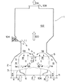
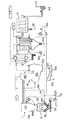
図1は、本発明のガス化方法を実施する第1実施例のガス化装置の主要部の図解的な縦断面図、図2は、図1のガス化装置の図解的な水平断面図である。図1に示されるガス化装置において、流動層炉2内へ炉底に配置される流動化ガス分散機構106を介し供給される流動化ガスは、炉底中央部4付近から炉内へ上向き流として供給される中央流動化ガス7及び炉底周辺部3から炉内へ上向き流として供給される周辺流動化ガス8から成る。
FIG. 1 is a schematic longitudinal sectional view of a main part of a gasifier of a first embodiment for carrying out the gasification method of the present invention, and FIG. 2 is a schematic horizontal sectional view of the gasifier of FIG. is there. In the gasifier shown in FIG. 1, the fluidizing gas supplied into the
第1表に示すように、中央流動化ガス7は、水蒸気、水蒸気と空気の混合気体、及び空気の3種の気体の内の1つであり、周辺流動化ガス8は、酸素、酸素と空気の混合気体、及び空気の3種の気体の内の1つである。中央流動化ガスの酸素含有量は、周辺流動化ガスの酸素含有量以下とされる。流動化ガス全体の空気量が、可燃物11の燃焼に必要な理論燃焼空気量の30%以下とされ、炉内は、還元雰囲気とされる。
As shown in Table 1, the
中央流動化ガス7の質量速度は、周辺流動化ガス8の質量速度より小にされ、炉内周辺部上方における流動化ガスの上向き流がデフレクタ6により炉の中央部へ向うように転向される。それによって、炉の中央部に流動媒体(一般的には硅砂を使用)が沈降拡散する移動層9が形成されると共に炉内周辺部に流動媒体が活発に流動化している流動層10が形成される。流動媒体は、矢印118で示すように、炉周辺部の流動層10を上昇し、次にデフレクタ6により転向され、移動層9の上方へ流入し、移動層9中を下降し、次に矢印112で示すように、ガス分散機構106に沿って移動し、流動層10の下方へ流入することにより、流動層10と移動層9の中を矢印118及び112で示すように循環する。
The mass velocity of the
可燃物供給口104から移動層9の上部へ供給された可燃物11は、流動媒体と共に移動層9中を下降する間に、流動媒体の持つ熱により加熱され、主として揮発分がガス化される。移動層9には、酸素が無いか少ないため、ガス化された揮発分から成る生成ガスは燃焼されないで、移動層9中を矢印116のように抜ける。それ故、移動層9は、ガス化ゾーンGを形成する。フリーボード102へ移動した生成ガスは、矢印120で示すように上昇し、ガス出口108から生成ガス29として排出される。
The
移動層9でガス化されない、主としてチャー(固定炭素分)やタール114は、移動層9の下部から、流動媒体と共に矢印112で示すように炉内周辺部の流動層10の下部へ移動し、比較的酸素含有量の多い周辺流動化ガス8により燃焼され、部分酸化される。流動層10は、可燃物の酸化ゾーンSを形成する。流動層10内において、流動媒体は、流動層内の燃焼熱により加熱され高温となる。高温になった流動媒体は、矢印118で示すように、傾斜壁6により反転され、移動層9へ移り、再びガス化の熱源となる。流動層10の温度は、450〜650℃に維持され、抑制された燃焼反応が継続するようにされる。
Mainly char (fixed carbon content) and
図1及び図2に示すガス化炉1によれば、流動層炉2にガス化ゾーンGと酸化ゾーンSが形成され、流動媒体が両ゾーンにおいて熱伝達媒体となることにより、ガス化ゾーンGにおいて、発熱量の高い良質の可燃ガスが生成され、酸化ゾーンSにおいては、ガス化困難なチャーやタール114を効率良く燃焼させることができる。それ故、可燃物のガス化効率を向上させることができ、良質の可燃ガスを生成することができる。
According to the
図2に示される流動層炉2の水平断面において、ガス化ゾーンGを形成する移動層9は、炉中心部において円形であり、酸化ゾーンSを形成する流動層10は、移動層9のまわりにリング状に形成される。流動層10の外周にリング状の不燃物排出口5が配置される。ガス化炉1を円筒形とすることにより、高い炉内圧を容易に支持することができる。ガス化炉自体により炉内圧を受ける構造に代えて、ガス化炉の外部に別途圧力容器(図示しない)を設けることができる。
In the horizontal section of the
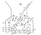
図3は、本発明のガス化方法を実施する第2実施例のガス化装置の主要部の図解的な縦断面図、図4は、図3のガス化装置の図解的な水平断面図である。図3に示される第2実施例のガス化装置において、流動化ガスは、中央流動化ガス7及び周辺流動化ガス8に加え、炉底中央部と炉底周辺部の間の炉底中間部から炉内へ供給される中間流動化ガス7’を含む。中間流動化ガス7’の質量速度は、中央流動化ガス7の質量速度と周辺流動化ガス8の質量速度の間に選定される。中間流動化ガスは、水蒸気、水蒸気及び空気の混合気体、又は空気の3種の気体の内のいずれか1つである。
FIG. 3 is a schematic vertical sectional view of a main part of a gasifier of a second embodiment for carrying out the gasification method of the present invention, and FIG. 4 is a schematic horizontal sectional view of the gasifier of FIG. is there. In the gasifier of the second embodiment shown in FIG. 3, the fluidizing gas includes a
図3のガス化装置において、図1のガス化装置の場合と同様に、中央流動化ガス7は、水蒸気、水蒸気と空気の混合気体、及び空気の3種の気体の内の1つであり、周辺流動化ガス8は、酸素、酸素と空気の混合気体、及び空気の3種の気体の内の1つである。中間流動化ガスの酸素含有量は、中央流動化ガスの酸素含有量と周辺流動化ガスの酸素含有量の間に選定される。それ故、流動化ガスの好適な組合せは、第2表の15通りである。各組合せにおいて、流動層炉の中央部から周辺部へ拡がっていくにつれて、酸素供給量が増加することが重要である。流動化ガス全体の空気量が、可燃物11の燃焼に必要な理論燃焼空気量の30%以下とされ、炉内は、還元雰囲気とされる。
In the gasifier of FIG. 3, as in the case of the gasifier of FIG. 1, the
図1のガス化装置の場合と同様に、図3のガス化装置において、炉の中央部に流動媒体が沈降する移動層9が形成され、炉の周辺部に流動媒体が上昇する流動層10が形成される。流動媒体が、矢印112及び118で示すように移動層及び流動層を通り循環する。移動層9と流動層10の間においては、流動媒体が、主として横方向に拡散する中間層9’が形成される。移動層9及び中間層9’がガス化ゾーンGを形成し、流動層10が酸化ゾーンSを形成する。
As in the case of the gasifier of FIG. 1, in the gasifier of FIG. 3, a moving
移動層9の上部へ投入された可燃物11は、流動媒体と共に移動層9中を下降する間に加熱され、その揮発分がガス化する。移動層9中でガス化されなかったチャー及びタール並びに一部の揮発分は、流動媒体と一緒に中間層9’及び流動層10へ移動し、部分的にガス化し部分的に燃焼される。中間層9’でガス化されない主としてチャー及びタールは、流動媒体と共に、炉周辺部の流動層10内へ移動し、比較的酸素含有量の多い周辺流動化ガス8中で燃焼される。流動媒体は、流動層10中で加熱され、移動層9へ循環し、移動層9中の可燃物を加熱する。中間層の酸素濃度については、可燃物の種類(揮発分が多いか、チャー、タール分が多いか)等により、酸素濃度を低くしてガス化を主体にするか、酸素濃度を高くして酸化燃焼を主体にするかが選定される。
The
図4に示す流動層炉の水平断面おいて、ガス化ゾーンを形成する移動層9は、炉中心部において円形であり、その外周に沿って中間流動化ガス7’により形成される中間ゾーン9’があり、酸化ゾーンを形成する流動層10は、中間ゾーン9’のまわりにリング状に形成される。流動層10の外周にリング状の不燃物排出口5が配置される。ガス化炉1を円筒形とすることにより、高い炉内圧を容易に支持することができる。炉内圧は、ガス化炉自体で受けるか、またはガス化炉の外部に別途圧力容器を設けてそれにより受けることができる。
In the horizontal section of the fluidized-bed furnace shown in FIG. 4, the moving
図5は、本発明の第3実施例のガス化装置の図解的な垂直断面図である。図5のガス化装置1において、ごみ等の可燃物からなるガス化原料11は、ダブルダンパー12、圧縮フィーダ13、及び給塵フィーダ14により、ガス化装置1の流動層炉2へ供給される。圧縮フィーダ13は、ガス化原料をプラグ状に圧縮し、これにより炉内圧がシールされる。プラグ状に圧縮されたごみは、図示しないほぐし器によりばらばらにされ、給塵フィーダ14により炉内へ送られる。
FIG. 5 is a schematic vertical sectional view of a gasifier according to a third embodiment of the present invention. In the
図5のガス化装置において、中央流動化ガス7及び周辺流動化ガス8は、図1の実施例と同様に供給され、それ故、図1の実施例と同様に、流動層炉2に還元雰囲気のガス化ゾーンと酸化ゾーンが形成される。流動媒体が両ゾーンにおいて熱伝達媒体となり、ガス化ゾーンにおいて、発熱量の高い良質の可燃ガスが生成され、また酸化ゾーンにおいて、ガス化困難なチャーやタール114が効率良く燃焼され、高いガス化効率と良質の可燃ガスが得られる。図5の実施例において、ダブルダンパ12とガス化炉1のフリーボード102に連通するルーツブロア15が設けられ、ごみの圧縮が不十分な場合に炉内から圧縮フィーダを通りダブルダンパ12へリークするガスを炉内へ戻す。好ましくは、ルーツブロア15は、ダブルダンパ12の上段部分が大気圧になるように、適当な量の空気及びガスをダブルダンパ12から吸引し炉内へ戻す。
In the gasifier of FIG. 5, the
図5のガス化装置において、流動層炉2から不燃物を排出するため、不燃物排出口5、円錐形シュート16、定量排出器17、シール用第1スイング弁18、スイングカット弁19、シール用第2スイング弁20、トロンメル付き排出器23が、順に配置され、次のように作動される。
In the gasifier of FIG. 5, in order to discharge incombustibles from the fluidized-
(1)シール用第1スイング弁18が開にされ、第2スイング弁20が閉にされて炉内圧が第2スイング弁20でシールされる状態において、定量排出器17が運転され、流動媒体の砂を含む不燃物が、円錐形シュート16内からスイングカット弁19へ排出される。(2)スイングカット弁19が所定量の不燃物を受けると、定量排出器17がOFFされ、第1スイング弁18が閉にされて炉内圧が第1スイング弁18でシールされる。そして排出弁22が開にされスイングカット弁19内が大気圧に戻される。次に第2スイング弁20が完全に開にされ、そしてスイングカット弁19が開にされることにより、不燃物がトロンメル付き連続排出器23へ排出される。(3)第2スイング弁20が完全に閉にされた後に、均圧弁21が開にされ、第1スイング弁18の内部と円錐形シュート16の内部が均圧にされてから、第1スイング弁18が開にされ、最初の工程(1)へ戻る。これらの工程(1)〜(3)は、自動的に繰り返し運転される。
(1) When the
トロンメル付き連続排出器23は、連続運転され、大きな不燃物27をトロンメルにより系外へ排出し、砂と小さな不燃物を砂循環エレベータ24により輸送し、分級器25により微細な不燃物28を除去した後、砂は、ロックホッパ26を介しガス化炉1へ戻される。このような不燃物排出機構は、2台のスイング弁が不燃物を受けずに圧力シール機能だけ有するので、第1及び第2スイング弁18、20のシール部における不燃物の噛込みを避けることができる。炉内圧が若干負圧でよい場合は、シール機能は不要である。
The
図6は、本発明の第4実施例のガス化装置の図解的な垂直断面図である。図6のガス化装置において、ガス化原料11の供給とそれに関係する炉内圧のシールは、図5の不燃物の排出のための機構と同様に、スイングカット弁19、19’及びシール用第1及び第2スイング弁18の組合せを使用して行われる。圧縮フィーダ13は、除かれている。図6の実施例において、炉内から第1スイング弁18内へ漏れたガスは、排出弁22及びブロア(図示しない)を介し、炉内へ戻される。また、第1スイング弁18を完全に閉じた後に均圧弁21が開とされ、スイングカット弁19内の圧力が炉内圧と同じにされる。
FIG. 6 is a schematic vertical sectional view of a gasifier according to a fourth embodiment of the present invention. In the gasifier of FIG. 6, the supply of the gasification
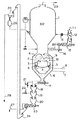
図7は、本発明のガス化装置により製造される生成ガスの精製工程の1例を示すフロー図である。図7の精製工程において、ガス化装置1へガス化原料11及び流動化ガス7、8がガス化炉1へ供給される。ガス化装置1において生成された可燃生成ガスは、廃熱ボイラ31で熱が回収され冷却されて、サイクロン分離器32へ送られ、固形分37、38が分離される。その後、生成ガスは、水洗浄塔33において水により洗浄され冷却され、アルカリ洗浄塔34において硫化水素を除去され、その後、ガスホルダー35に貯留される。サイクロン分離器32で分離された固形分の内の未反応チャー37は、ガス化装置1へ戻され、残りの固形分38は、系外へ排出される。図5の実施例と同様に、ガス化装置1から排出された不燃物の内、大きな不燃物27は、系外へ排出され、砂は、ガス化装置1へ戻される。洗浄塔33、34から出る廃水は、廃水処理器36へ導入され、無害化処理される。
FIG. 7 is a flowchart showing an example of the purification process of the product gas produced by the gasifier of the present invention. In the refining process of FIG. 7, the
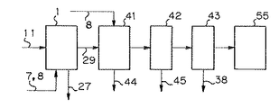
図8は、ガス化装置1において発生した可燃生成ガス及び微粒子が、熔融燃焼炉41に導入されて高温燃焼され、灰が熔融される工程の1例を示すフロー図である。図8の工程において、ガス化装置1で製造された可燃分の多い生成ガスが、熔融燃焼炉41へ導入される。熔融燃焼炉41には、酸素、酸素と空気の混合気体、又は空気が吹き込まれ、生成ガス及び微粒子が1300℃以上で燃焼され、灰が熔融され、またダイオキシン、PCB等の有害物質が分解される。熔融燃焼炉41で熔融された灰44は、急冷されスラグとされ減量化される。熔融燃焼炉41で発生した燃焼排気ガスは、スクラバー42で急冷され、ダイオキシンの再合成が防止される。スクラバー41で急冷された排気ガスは、フィルター43において更に塵埃38が除去され、排気塔55から大気へ排出される。
FIG. 8 is a flowchart showing an example of a process in which the combustible product gas and the fine particles generated in the
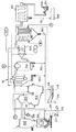
図9は、本発明の第5実施例のガス化及び熔融燃焼装置の垂直断面斜視図である。図9において、ガス化装置1は、図1の実施例とほぼ同一であるが、ガス出口108は、熔融燃焼炉41の可燃ガス入口142に連通されている。熔融燃焼炉41は、ほぼ垂直方向の軸線を有する円筒形一次燃焼室140、及び水平方向に傾斜する二次燃焼室150を含む。流動層炉2で発生された可燃ガス120及び微粒子は、可燃ガス入口142を介し一次燃焼室140へその軸線のまわりに旋回するように供給される。
FIG. 9 is a vertical sectional perspective view of a gasification and melting and burning apparatus according to a fifth embodiment of the present invention. 9, the
一次燃焼室140は、上端に始動バーナを備えると共に、燃焼用空気を軸線のまわりに旋回するように供給する複数の空気ノズル134を備える。二次燃焼室150は、一次燃焼室140とその下端で連通されると共に、二次燃焼室の下方部分に配置され熔融灰分を排出可能な排出口152、排出口152の上方に配置される排気口154、一次燃焼室と連通する部分の付近に配置される助燃バーナ136、及び燃焼用空気を供給する空気ノズル134を備える。排気口154は、輻射板162を備え、輻射により排気口154から失われる熱量を減少させている。
The
図10は、廃熱ボイラ及びタービンと組み合わせて使用される本発明の実施例の流動層ガス化及び熔融燃焼装置の配置図である。図10において、ガス化装置1は、排出器23から排出された大きな不燃物27及び分級器25から排出された微細な不燃物28を一緒に搬送するコンベヤ172を具備する。流動層炉2の下部から不燃物を取り出す円錐形シュート16のまわりに空気ジャケット185が配置され、高温の抜き出し砂により空気ジャケット185内の空気が加熱される。補助燃料Fが、熔融燃焼炉41の一次及び二次燃焼室140、150へ供給される。熔融燃焼炉41の排出口152から排出される熔融状態の灰44は、水室178に受け入れられ急冷されて、スラグ176として排出される。
FIG. 10 is a layout view of a fluidized bed gasification and melting and combustion apparatus according to an embodiment of the present invention used in combination with a waste heat boiler and a turbine. In FIG. 10, the
図10において、熔融燃焼炉41から排出される燃焼ガスは、廃熱ボイラ31、エコノマイザ183、空気予熱器186、集塵器43、誘引通風機54を経て大気へ排出される。空気予熱器186から出た燃焼ガスは、集塵器43に入る前に、消石灰等の中和剤Nを添加される。水Wがエコノマイザ183へ供給され、予熱された後、ボイラ31で加熱されて蒸気にされ、蒸気タービンSTを駆動する。空気Aが空気予熱器186へ供給され、加熱された後、空気ジャケット185で更に加熱され、空気管184を介し、熔融燃焼炉41、及び必要に応じてフリーボード102へ供給される。
In FIG. 10, the combustion gas discharged from the melting and burning
廃熱ボイラ31、エコノマイザ183、及び空気予熱器186の底部に溜まる微粒子180、190は、砂循環エレベータ24で分級器25へ搬送され微細な不燃物28が除去され、流動層炉2へ戻される。フィルター43において分離される飛灰38は、高温で揮散したNa、Kなどのアルカリ金属塩を含むので、処理器194において薬品により処理される。
The
図10の装置においては、流動層炉2の燃焼が低空気比による低温部分燃焼とされ、流動層温度が450℃〜650℃に維持されることにより、高熱量の可燃ガスを発生させることができる。また、低空気比により還元雰囲気で燃焼が行われるので、不燃物中に鉄、アルミが未酸化の有価物として得られる。流動層炉2で発生された高熱量の可燃ガス及びチャーは、熔融燃焼炉41において、1300℃以上の高温燃焼することができ、灰を熔融させ、ダイオキシンを分解させることができる。
In the apparatus of FIG. 10, the combustion in the fluidized-
図11は、ガス冷却室280と組み合わせて使用される本発明の実施例の流動層ガス化及び熔融燃焼装置の配置図である。図11において、ガス化装置1、熔融燃焼炉41、水室178、集塵器43、誘引通風機54等は、図10と同様である。図11においては、廃熱ボイラに代えて、ガス冷却器280、独立空気予熱器188が設けられ、熔融燃焼炉41から高温燃焼排ガスを耐火断熱被覆された高温ダクト278を介してガス冷却器280に導入する。ガス冷却器280において、燃焼ガスは、微細水噴霧により、瞬時に減温され、ダイオキシンの再合成が防止される。高温ダクト278の排ガス流速は、5m/秒以下の低速とされる。ガス冷却器280の上部に温水発生器283が配置される。空気予熱器188で加熱された空気がガス化炉1のフリーボード102及び熔融燃焼炉41へ供給される。
FIG. 11 is a layout diagram of a fluidized bed gasification and melting and combustion apparatus according to an embodiment of the present invention used in combination with the
図12は、廃熱ボイラ31及び反応塔310と組み合わせて使用される本発明の実施例の流動層ガス化及び熔融燃焼装置の配置図である。図12において、ガス化装置1、熔融燃焼炉41、水室178、廃熱ボイラ31、蒸気タービンST、エコノマイザ183、空気予熱器186、集塵器43、誘因通風機54等は、図10と同様である。図12においては、廃熱ボイラ31とエコノマイザ183の間に、反応塔310、スーパーヒータ加熱燃焼器320が配置される。反応塔310において、消石灰スラリー等の中和剤Nが燃焼排ガスに添加され、HClが除去される。反応塔310から排出される固体微粒子312は、廃熱ボイラ31から排出される固体微粒子180と一緒に砂循環エレベータ24により分級器25へ送られる。加熱燃焼器320において、未燃焼ガス及び補助燃料Fを燃焼させ、蒸気温度を500℃程度に上げる。図12の装置においては、蒸気が高温高圧であることと、空気比が小さく排ガスの持ち出し顕熱が小さいことにより、発電効率を約30%とすることができる。
FIG. 12 is a layout diagram of a fluidized bed gasification and melting and burning apparatus according to an embodiment of the present invention used in combination with the
図13は、本発明の実施例のガス化コジェネレーション型の流動層ガス化及び熔融燃焼装置の配置図である。図13において、ガス化装置1、熔融燃焼炉41、水室178、廃熱ボイラ31、集塵器43、誘引通風機54等は、図10の装置と同様である。図13においては、廃熱ボイラ31と集塵器43の間に反応塔310が配置され、反応塔310において、消石灰スラリー等の中和剤Nが燃焼排ガスに添加され、HClが除去される。反応塔310の排ガスが、集塵器43を経てガスタービン420で使用される。ガスタービン420においては、空気Aが圧縮機Cにより圧縮され燃焼器CCに供給され、燃焼器CCにおいて燃料Fが燃焼され、この燃焼ガス及び圧縮機410で圧縮されて燃焼器CCへ供給され排ガスが、タービンTの作動流体となる。ガスタービン420の排気ガスは、スーパーヒータ430、節炭器440、及び空気予熱器450を順に通過され、誘因通風機54により大気へ放出される。廃熱ボイラ31において発生された蒸気が、スーパーヒータ430において、ガスタービン420の排気ガスにより加熱され、蒸気タービンSTへ供給される。
FIG. 13 is a layout view of a gasification cogeneration type fluidized bed gasification and fusion combustion apparatus according to an embodiment of the present invention. 13, a
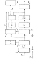
図14は、本発明の実施例の加圧ガス化複合発電型の流動層ガス化及び熔融燃焼方法の工程を示すフロー図である。加圧型のガス化炉1で生成された高温高圧の生成ガス29は、廃熱ボイラ31’へ導入され、蒸気を発生させると共にそれ自体は冷却される。廃熱ボイラを出た生成ガスは、2分され、一方が熔融燃焼炉41へ他方が中和剤Nを添加されHClが中和されて集塵器43’へ導入される。集塵器43’において、温度低下により固化した生成ガス中の低融点物質が、生成ガスから分離されて熔融燃焼炉41へ送られ、熔融される。低融点物質が除去された生成ガスが、ガスタービンGTにおいて燃料ガスとして利用される。ガスタービンGTの排気ガスは、スーパーヒータSH、エコノマイザECoで熱交換され、その後、排ガス処理器510で処理され、大気中へ放出される。熔融燃焼炉41の排気ガスは、熱交換器EX、集塵器43を経て、排ガス処理器510へ導入される。熔融炉から排出された熔融灰44は、急冷しスラグにされる。集塵器43から排出された固形分38は、処理器194において薬品処理される。
FIG. 14 is a flow chart showing the steps of the fluidized bed gasification and melt combustion method of the combined pressurized gasification power generation type of the embodiment of the present invention. The high-temperature and high-pressure generated
図14の工程によれば、廃棄物から生成されたガスが、HCl及び固形分が除去された後、燃料として使用されるから、ガスタービンを腐食させるることがなく、また、HClが除去されているので、ガスタービン排気ガスにより高温の蒸気を発生させることができる。 According to the process of FIG. 14, the gas generated from the waste is used as a fuel after the HCl and solids are removed, so that the gas turbine is not corroded and the HCl is removed. Therefore, high-temperature steam can be generated by the gas turbine exhaust gas.
1;ガス化装置、2;流動層炉、3;炉底周辺部、4;炉底中央部、5;不燃物排出口、6;傾斜壁、7;中央流動化ガス、7’;中間流動化ガス、8;周辺流動化ガス、9;移動層、9’;中間層、10;流動層、11;ガス化原料(可燃物)、12;ダブルダンパー、13;圧縮フィーダ、14;給塵フィーダ、15;ルーツブロア、16;円錐形シュート、17;定量排出器、18、20;スイング弁、19、19’;スイングカット弁、22;排出弁、23;トロンメル付き連続排出器、24;砂循環エレベータ、25;分級器、27、28;不燃物、29;生成ガス、31、31’;廃熱ボイラ、32;サイクロン分離機、36;廃水処理器、37;未反応チャー、38;固形分、41;熔融燃焼炉、43、43’;集塵器、44;熔融灰、54;誘引通風機、55;排気塔、102;フリーボード、104;可燃物供給口、106;ガス分散機構、108;ガス出口、114;チャー・タール、134;助燃バーナ、140;一次燃焼室、142;可燃ガス入口、150;二次燃焼室、162;輻射板、176;スラグ、178;水室、183;エコノマイザ、185;空気ジャケット、186、188;空気予熱器、194、510;処理器、280;ガス冷却器、310;反応塔、320;スーパーヒータ加熱燃焼器、420;ガスタービン、A;空気、C;圧縮機、CC;燃焼器、ECo;エコノマイザ、F;補助燃料、G;ガス化ゾーン、N;中和剤、S;酸化ゾーン、SH;スーパーヒータ、ST;蒸気タービン、T;タービン、W;水。
DESCRIPTION OF SYMBOLS 1; Gasification apparatus, 2; Fluidized bed furnace, 3; Furnace bottom peripheral part, 4; Furnace bottom central part, 5; Noncombustible material discharge port, 6; Inclined wall, 7; Central fluidizing gas, 7 '; Gasification gas, 8; Peripheral fluidization gas, 9; Moving bed, 9 '; Intermediate layer, 10; Fluidized bed, 11; Gasification raw material (combustible material), 12; Double damper, 13; Compression feeder, 14; Feeder, 15; Roots blower, 16; Conical chute, 17; Constant discharger, 18, 20; Swing valve, 19, 19 '; Swing cut valve, 22; Discharge valve, 23; Continuous discharger with trommel, 24; Recirculation elevator, 25; Classifier, 27, 28; Noncombustible, 29; Product gas, 31, 31 '; Waste heat boiler, 32; Cyclone separator, 36; Wastewater treatment unit, 37; Unreacted char, 38; Min, 41; melting and burning furnace, 43, 43 '; dust collector, 44; melting Induction ventilator, 55; Exhaust tower, 102; Free board, 104; Combustible material supply port, 106; Gas dispersion mechanism, 108; Gas outlet, 114; Char tar, 134; Combustion burner, 140; Primary combustion Combustion gas inlet, 150; Secondary combustion chamber, 162; Radiant plate, 176; Slag, 178; Water chamber, 183; Economizer, 185; Air jacket, 186, 188; Air preheater, 194, 510; Processor, 280; Gas cooler, 310; Reaction tower, 320; Super heater heating combustor, 420; Gas turbine, A; Air, C; Compressor, CC; Combustor, ECo; Economizer, F: Auxiliary fuel, G: gasification zone, N: neutralizer, S: oxidation zone, SH: super heater, ST: steam turbine, T: turbine, W: water.
Claims (6)
流動媒体からなる流動層を備え、該流動層の温度を450℃〜650℃に維持し、都市ごみを受け入れて該流動層内で加熱しガスとチャーとを生成する流動層炉と、
該流動層炉から生成した該ガスと該チャーを導入すると共に、酸素、又は酸素と空気の混合気体を導入し、該ガスと該チャーとを燃焼して該チャーに随伴する灰分を熔融する熔融炉と、
を有することを特徴とするガス化及び熔融装置。 After gasifying municipal solid waste, the ash melts,
A fluidized bed furnace comprising a fluidized bed made of a fluidized medium, maintaining the temperature of the fluidized bed at 450 ° C. to 650 ° C., receiving municipal solid waste, and heating the fluidized bed to generate gas and char;
Introducing the gas and the char generated from the fluidized bed furnace and introducing oxygen or a mixed gas of oxygen and air, and burning the gas and the char to melt ash accompanying the char. Furnace and
A gasification and melting apparatus characterized by having:
該円筒形燃焼室の上端部分に該酸素、又は酸素と空気の混合気体を上記軸線のまわりに旋回するように供給する複数のノズルを備える
ことを特徴とする請求項1若しくは2に記載のガス化及び熔融装置。 The melting furnace includes a cylindrical combustion chamber having a substantially vertical axis, and the gas and char generated in the fluidized bed furnace are transferred from an upper end of the cylindrical combustion chamber around the axis of the cylindrical combustion chamber. It is made to supply so as to turn,
The gas according to claim 1 or 2, further comprising a plurality of nozzles for supplying the oxygen or the mixed gas of oxygen and air to the upper end portion of the cylindrical combustion chamber so as to swirl around the axis. And melting equipment.
流動層炉内の流動層の温度を450℃〜650℃に維持し、都市ごみを受け入れて該流動層内で加熱しガスとチャーとを生成し、
該流動層炉から生成した該ガスと該チャーを該熔融炉に供給し、
該熔融炉に酸素、又は酸素と空気の混合気体を導入し、
該ガスと該チャーとを燃焼してチャーに随伴する灰分を熔融する、
ことを特徴とするガス化及び熔融方法。 In the method of melting ash after gasifying municipal solid waste,
Maintaining the temperature of the fluidized bed in the fluidized bed furnace at 450 ° C. to 650 ° C., receiving municipal solid waste and heating in the fluidized bed to generate gas and char,
Supplying the gas and the char generated from the fluidized bed furnace to the melting furnace,
Introducing oxygen or a mixed gas of oxygen and air into the melting furnace,
Melting the ash accompanying the char by burning the gas and the char;
A gasification and melting method characterized by the above-mentioned.
該円筒形燃焼室の上端部分において該酸素、又は酸素と空気の混合気体を上記軸線のまわりに旋回するように供給するようにした
ことを特徴とする請求項4若しくは5に記載のガス化及び熔融方法。 The melting furnace includes a cylindrical combustion chamber having a substantially vertical axis, and the gas and char generated in the fluidized bed furnace are transferred from the upper end of the cylindrical combustion chamber to the axis of the cylindrical combustion chamber. Supply to swirl around
The gasification and gasification system according to claim 4 or 5, wherein the oxygen or the mixed gas of oxygen and air is supplied so as to swirl around the axis at an upper end portion of the cylindrical combustion chamber. Melting method.
Priority Applications (1)
| Application Number | Priority Date | Filing Date | Title |
|---|---|---|---|
| JP2004077256A JP2004264017A (en) | 1994-03-10 | 2004-03-17 | Municipal waste gasification furnace and method |
Applications Claiming Priority (3)
| Application Number | Priority Date | Filing Date | Title |
|---|---|---|---|
| JP6543994 | 1994-03-10 | ||
| JP10154194 | 1994-04-15 | ||
| JP2004077256A JP2004264017A (en) | 1994-03-10 | 2004-03-17 | Municipal waste gasification furnace and method |
Related Parent Applications (1)
| Application Number | Title | Priority Date | Filing Date |
|---|---|---|---|
| JP2001146105A Division JP3544953B2 (en) | 1994-03-10 | 2001-05-16 | Waste treatment method and gasification and melting equipment |
Publications (2)
| Publication Number | Publication Date |
|---|---|
| JP2004264017A true JP2004264017A (en) | 2004-09-24 |
| JP2004264017A5 JP2004264017A5 (en) | 2005-05-26 |
Family
ID=33135598
Family Applications (1)
| Application Number | Title | Priority Date | Filing Date |
|---|---|---|---|
| JP2004077256A Pending JP2004264017A (en) | 1994-03-10 | 2004-03-17 | Municipal waste gasification furnace and method |
Country Status (1)
| Country | Link |
|---|---|
| JP (1) | JP2004264017A (en) |
Cited By (2)
| Publication number | Priority date | Publication date | Assignee | Title |
|---|---|---|---|---|
| CN100445352C (en) * | 2006-06-24 | 2008-12-24 | 中国科学院山西煤炭化学研究所 | Method for preparing fuel gas by fluidized bed co-gasification of biomass and coal |
| KR20230051780A (en) * | 2021-10-08 | 2023-04-19 | 장우기계 주식회사 | Biomass power generation system |
-
2004
- 2004-03-17 JP JP2004077256A patent/JP2004264017A/en active Pending
Cited By (3)
| Publication number | Priority date | Publication date | Assignee | Title |
|---|---|---|---|---|
| CN100445352C (en) * | 2006-06-24 | 2008-12-24 | 中国科学院山西煤炭化学研究所 | Method for preparing fuel gas by fluidized bed co-gasification of biomass and coal |
| KR20230051780A (en) * | 2021-10-08 | 2023-04-19 | 장우기계 주식회사 | Biomass power generation system |
| KR102556454B1 (en) | 2021-10-08 | 2023-07-20 | 장우기계 주식회사 | Biomass power generation system |
Similar Documents
| Publication | Publication Date | Title |
|---|---|---|
| JP3153091B2 (en) | Waste treatment method and gasification and melting and combustion equipment | |
| EP0908672B1 (en) | Methods for fusion treating a solid waste for gasification | |
| US6709636B1 (en) | Method and apparatus for gasifying fluidized bed | |
| JPH11173520A (en) | Method and device for fluidized bed type thermal decomposition | |
| JP2007147270A (en) | Processing method, and gasifying and melting device for waste | |
| JP3270457B1 (en) | Waste treatment method and gasification and melting equipment | |
| JP3544953B2 (en) | Waste treatment method and gasification and melting equipment | |
| JP3270447B2 (en) | Waste treatment method and gasification and melting equipment | |
| JP2004251618A (en) | Processing method and gasifying and fusing apparatus for combustible material | |
| JP2004264017A (en) | Municipal waste gasification furnace and method | |
| JP3270454B1 (en) | Waste treatment method and gasification and melting equipment | |
| JP3270455B2 (en) | Waste treatment method and gasification and melting equipment | |
| JP3270456B2 (en) | Waste treatment method and gasification and melting equipment | |
| KR100482887B1 (en) | Fluidized Bed Gasification and Melting Combustion Method and Apparatus | |
| JP2004264018A (en) | Processing method, and gasifying and melting device for waste | |
| JP3270453B1 (en) | Waste treatment method and gasification and melting equipment | |
| JP3270452B2 (en) | Waste treatment method and gasification and melting equipment | |
| JP2004264017A5 (en) | ||
| JP2002115830A (en) | Method for waste treatment and gasification and melting apparatus | |
| JP2002130630A (en) | Processing method for waste, and gasifying and melting apparatus for waste | |
| JP2006105448A (en) | Sludge and incinerated ash gasified melting method and gasifying melting furnace | |
| JP2002147724A (en) | Waste disposal method and gasifying and melting device | |
| JP2003090520A (en) | Gasifying furnace and gasifying method for combustible substance | |
| JP2002130633A (en) | Waste processing method, and waste gasifying and melting apparatus | |
| JP3046309B1 (en) | Method and apparatus for reducing dioxins in a garbage gasifier for char separation |
Legal Events
| Date | Code | Title | Description |
|---|---|---|---|
| A521 | Request for written amendment filed |
Free format text: JAPANESE INTERMEDIATE CODE: A523 Effective date: 20040908 |
|
| A521 | Request for written amendment filed |
Free format text: JAPANESE INTERMEDIATE CODE: A523 Effective date: 20040924 |
|
| A977 | Report on retrieval |
Free format text: JAPANESE INTERMEDIATE CODE: A971007 Effective date: 20061004 |
|
| A131 | Notification of reasons for refusal |
Free format text: JAPANESE INTERMEDIATE CODE: A131 Effective date: 20061017 |
|
| A521 | Request for written amendment filed |
Free format text: JAPANESE INTERMEDIATE CODE: A523 Effective date: 20061218 |
|
| RD01 | Notification of change of attorney |
Free format text: JAPANESE INTERMEDIATE CODE: A7426 Effective date: 20061129 |
|
| RD13 | Notification of appointment of power of sub attorney |
Free format text: JAPANESE INTERMEDIATE CODE: A7433 Effective date: 20061129 |
|
| A521 | Request for written amendment filed |
Free format text: JAPANESE INTERMEDIATE CODE: A821 Effective date: 20061218 |
|
| A131 | Notification of reasons for refusal |
Free format text: JAPANESE INTERMEDIATE CODE: A131 Effective date: 20070515 |
|
| A02 | Decision of refusal |
Free format text: JAPANESE INTERMEDIATE CODE: A02 Effective date: 20070918 |