JP2004263888A - Setter for baking - Google Patents
Setter for baking Download PDFInfo
- Publication number
- JP2004263888A JP2004263888A JP2003037991A JP2003037991A JP2004263888A JP 2004263888 A JP2004263888 A JP 2004263888A JP 2003037991 A JP2003037991 A JP 2003037991A JP 2003037991 A JP2003037991 A JP 2003037991A JP 2004263888 A JP2004263888 A JP 2004263888A
- Authority
- JP
- Japan
- Prior art keywords
- setter
- flat plate
- leg
- view
- electronic components
- Prior art date
- Legal status (The legal status is an assumption and is not a legal conclusion. Google has not performed a legal analysis and makes no representation as to the accuracy of the status listed.)
- Pending
Links
Images


Classifications
-
- F—MECHANICAL ENGINEERING; LIGHTING; HEATING; WEAPONS; BLASTING
- F27—FURNACES; KILNS; OVENS; RETORTS
- F27D—DETAILS OR ACCESSORIES OF FURNACES, KILNS, OVENS, OR RETORTS, IN SO FAR AS THEY ARE OF KINDS OCCURRING IN MORE THAN ONE KIND OF FURNACE
- F27D3/00—Charging; Discharging; Manipulation of charge
- F27D3/12—Travelling or movable supports or containers for the charge
-
- F—MECHANICAL ENGINEERING; LIGHTING; HEATING; WEAPONS; BLASTING
- F27—FURNACES; KILNS; OVENS; RETORTS
- F27D—DETAILS OR ACCESSORIES OF FURNACES, KILNS, OVENS, OR RETORTS, IN SO FAR AS THEY ARE OF KINDS OCCURRING IN MORE THAN ONE KIND OF FURNACE
- F27D5/00—Supports, screens, or the like for the charge within the furnace
Abstract
Description
【0001】
【発明の属する技術分野】
本発明は、電子部品の焼成の際に、電子部品を載置し、かつ多段に積み重ねて窯炉に装入するセッターに関するものである。
【0002】
【従来の技術】
一般に電子部品の製造工程において、電子部品を焼成する際にはセッターと呼ばれる治具を使用する。すなわち、電子部品をセッターの平皿部に載置し、さらにそのセッターを多段に積み重ねて窯炉に装入して、電子部品の焼成を行なう。
図4は、従来から使用されているセッターの例を模式的に示す図であり、(a) は平面図、(b) は横側面図、(c) は縦側面図である。
【0003】
セッターには平坦な耐火物からなる平皿部1が設けられており、この平皿部1に電子部品(図示せず)を載置する。平皿部1の周縁部には、脚部2が設けられており、セッターを積み重ねたときに安定させるとともに、平皿部1上の電子部品が破損するのを防止する。従来から脚部2は、図4に示すように平皿部1の片面側に突出するように設けられている。ここでは脚部2が平皿部1から突出する側の面(すなわち図4(b) に示す横側面図における上側の面)を上面とする。
【0004】
焼成を行なう際には、このような脚部2を有するセッターの平皿部1に電子部品を載置して、さらにそのセッターを多段に積み重ねて窯炉に装入する。焼成が終了した後、窯炉から取り出して、電子部品は次の工程に送給する。一方、セッターは新たな電子部品を載置して窯炉に再度装入される。つまりセッターは繰り返し使用されるものであり、熱による膨張と収縮の繰り返し、載置する電子部品の荷重および電子部品との反応等により、変形や亀裂が生じる。
【0005】
従来は、図4に示すような平皿部1の上面のみを使用する脚部2が平皿部1の上面側のみに突出したセッターが使用されてきた。その結果、セッターを繰り返し使用することによって、荷重が一定方向であることおよび片面のみ電子部品と接するため、片面のみ変質しやすいことより、変形や亀裂が生じやすくなる。しかも平皿部1上面と電子部品との焼き付きも生じやすくなる。
【0006】
セッターの変形や亀裂が生じた場合、あるいは平皿部1上面と電子部品との焼き付きが生じた場合には、そのセッターは廃却せざるを得ない。したがって図4に示すような、脚部2が平皿部1の上面側のみに突出したセッターを繰り返し使用できる回数は比較的少ない。
そこで、このようなセッターの耐用性を向上するめたに、耐熱性を高めた材質で製作したり、あるいは載置する電子部品と反応しにくい材料でコーティングする技術が検討されている(たとえば特許文献1参照)。しかし、そのような特性を有する材料は高価であるから、電子部品の焼成コストの上昇を招く。
【0007】
【特許文献1】
特開2000−74571号公報
【0008】
【発明が解決しようとする課題】
本発明は上記のような問題点を解消し、安価でかつ優れた耐用性を有するセッターを提供することを目的とする。
【0009】
【課題を解決するための手段】
本発明は、電子部品の焼成を行なう際に使用するセッターであって、平坦な耐火物からなる平皿部の上面側および下面側に突出した脚部を、平皿部の周縁に4個以上設けるセッターである。
また好適態様として、脚部の上端面に凸部を設け、凸部に嵌合可能な凹部を脚部の下端面に設けることが好ましい。
【0010】
【発明の実施の形態】
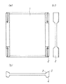
図1は、本発明のセッターの例を模式的に示す図であり、(a) は平面図、(b) は横側面図、(c) は縦側面図である。
セッターには平坦な耐火物からなる平皿部1が設けられており、この平皿部1に電子部品(図示せず)を載置する。平皿部1の周縁部には、脚部2が設けられており、セッターを積み重ねたときに安定させるとともに、平皿部1上の電子部品が破損するのを防止する。
【0011】
本発明のセッターの脚部2は、図1に示すように平皿部1の上面側および下面側に突出するように設けられる。ここでは図1(b) に示す横側面図における上側の面を上面とする。
焼成を行なう際には、セッターの平皿部1に電子部品を載置して、さらにそのセッターを多段に積み重ねて窯炉に装入する。セッターを多段に積み重ねると、上段のセッターの脚部2の下端面と、下段のセッターの脚部2の上端面とが接触するので、安定して積み重ねることが可能である。
【0012】
ただし脚部2は、平皿部1の周縁部に少なくとも3個を設け、さらに平皿部1の寸法や重量に応じて、中間部分に脚部2を適宜設置する。図1には、6ケ所に脚部2を設ける例を示す。
さらに本発明のセッターは、平皿部1の上面と下面の両面を使用できる。したがって、セッターを繰り返し使用するにあたって、適宜セッターを反転させ、平皿部1の上面と下面に交互に電子部品を載置して焼成を行なうことによって、載置する電子部品の荷重や電子部品との反応に起因する変形や亀裂を抑制できる。
このようにしてセッターの耐用性を高めることが可能である。
【0013】
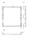
ただし図1に示したセッターは、多段に積み重ねたときに、ズレが生じて倒壊する危険性がある。そこで図2に示すように、脚部2の上端面に凸部3を設け、その凸部3に嵌合可能な凹部4を脚部2の下端面に設けることが好ましい。図2に示したセッターを多段に積み重ねると、上段のセッターの脚部2の下端面と、下段のセッターの脚部2の上端面とが接触するとともに、上段のセッターの脚部2の凹部4と、下段のセッターの脚部2の凸部3とが互いに嵌合するので、安定して積み重ねて、かつズレを防止することが可能である。
【0014】
脚部2に設ける凸部3と凹部4の寸法や形状は、特定の構成に限定しない。たとえば図2に示す例の他に、図3に示すような凸部3と凹部4を脚部2に設けることも可能である。
このようにして本発明では、セッターの材質やコーティングについて格別に配慮する必要はなく、簡便な手段で安価でかつ優れた耐用性を有するセッターを得ることができる。
【0015】
【実施例】
図3に示す形状のセッターを使用して、電子部品の焼成を行なった。その際、平皿部1の上面に電子部品を載置して焼成を行なった後、セッターを反転させて、次に平皿部1の下面に電子部品を載置して焼成を行なった。このようにして平皿部1の上面と下面に交互に電子部品を載置して、セッターを繰り返し使用した。これを発明例とする。
【0016】
一方、 従来は図4に示す形状のセッターを使用していた。その際、平皿部1の上面のみに電子部品を載置して、セッターを繰り返し使用した。これを従来例とする。
発明例と従来例について、セッターの耐用性を調査したところ、発明例では平均 100回程度の繰り返し使用が可能であったのに対して、従来例では平均30回程度であった。
【0017】
【発明の効果】
本発明によれば、 安価でかつ優れた耐用性を有するセッターを得ることができる。
【図面の簡単な説明】
【図1】本発明のセッターの例を模式的に示す図であり、(a) は平面図、(b) は横側面図、(c) は縦側面図である。
【図2】本発明のセッターの他の例を模式的に示す図であり、(a) は平面図、(b) は横側面図、(c) は縦側面図である。
【図3】本発明のセッターの他の例を模式的に示す図であり、(a) は平面図、(b) は横側面図、(c) は縦側面図である。
【図4】従来のセッターの例を模式的に示す図であり、(a) は平面図、(b) は横側面図、(c) は縦側面図である。
【符号の説明】
1 平皿部
2 脚部
3 凸部
4 凹部[0001]
TECHNICAL FIELD OF THE INVENTION
The present invention relates to a setter in which electronic components are placed, stacked in multiple stages, and charged into a kiln when firing the electronic components.
[0002]
[Prior art]
Generally, in a process of manufacturing an electronic component, a jig called a setter is used when firing the electronic component. That is, the electronic components are placed on the flat plate portion of the setter, and the setters are stacked in multiple stages and charged into a kiln to fire the electronic components.
FIGS. 4A and 4B are diagrams schematically illustrating an example of a setter conventionally used, in which FIG. 4A is a plan view, FIG. 4B is a lateral side view, and FIG. 4C is a vertical side view.
[0003]
The setter is provided with a
[0004]
When firing, electronic components are placed on the
[0005]
Conventionally, as shown in FIG. 4, a setter in which the
[0006]
If the setter is deformed or cracked, or if the upper surface of the
In order to improve the durability of such a setter, a technique of manufacturing a material with improved heat resistance or coating with a material that does not easily react with mounted electronic components has been studied (for example, Patent Documents). 1). However, since a material having such characteristics is expensive, the firing cost of the electronic component is increased.
[0007]
[Patent Document 1]
JP 2000-74571 A [0008]
[Problems to be solved by the invention]
SUMMARY OF THE INVENTION An object of the present invention is to solve the above problems and provide a setter which is inexpensive and has excellent durability.
[0009]
[Means for Solving the Problems]
The present invention relates to a setter for use in firing electronic components, wherein four or more legs protruding from the upper surface and the lower surface of a flat plate made of a refractory material are provided on the periphery of the flat plate. It is.
As a preferred embodiment, it is preferable that a convex portion is provided on the upper end surface of the leg portion, and a concave portion that can be fitted to the convex portion is provided on the lower end surface of the leg portion.
[0010]
BEST MODE FOR CARRYING OUT THE INVENTION
FIG. 1 is a diagram schematically showing an example of the setter of the present invention, wherein (a) is a plan view, (b) is a lateral side view, and (c) is a longitudinal side view.
The setter is provided with a
[0011]
The
When firing, electronic components are placed on the
[0012]
However, at least three
Further, the setter of the present invention can use both the upper surface and the lower surface of the
In this way, it is possible to increase the durability of the setter.
[0013]
However, there is a risk that the setters shown in FIG. Therefore, as shown in FIG. 2, it is preferable that the
[0014]
The size and shape of the
In this way, in the present invention, it is not necessary to particularly consider the material and coating of the setter, and a setter having low cost and excellent durability can be obtained by simple means.
[0015]
【Example】
The electronic component was fired using a setter having the shape shown in FIG. At this time, after the electronic component was placed on the upper surface of the
[0016]
On the other hand, conventionally, a setter having the shape shown in FIG. 4 has been used. At that time, the electronic component was placed only on the upper surface of the
When the durability of the setter was investigated for the invention example and the conventional example, it was found that the invention example could be repeatedly used about 100 times on average, whereas the conventional example was about 30 times on average.
[0017]
【The invention's effect】
According to the present invention, a setter which is inexpensive and has excellent durability can be obtained.
[Brief description of the drawings]
FIG. 1 is a view schematically showing an example of a setter of the present invention, wherein (a) is a plan view, (b) is a lateral side view, and (c) is a longitudinal side view.
FIG. 2 is a view schematically showing another example of the setter of the present invention, wherein (a) is a plan view, (b) is a lateral side view, and (c) is a longitudinal side view.
3A and 3B are diagrams schematically illustrating another example of the setter of the present invention, wherein FIG. 3A is a plan view, FIG. 3B is a lateral side view, and FIG. 3C is a vertical side view.
4A and 4B are diagrams schematically showing an example of a conventional setter, wherein FIG. 4A is a plan view, FIG. 4B is a lateral side view, and FIG. 4C is a vertical side view.
[Explanation of symbols]
1
Claims (2)
Priority Applications (8)
| Application Number | Priority Date | Filing Date | Title |
|---|---|---|---|
| JP2003037991A JP2004263888A (en) | 2003-02-17 | 2003-02-17 | Setter for baking |
| CNA2004800042333A CN1751215A (en) | 2003-02-17 | 2004-02-12 | Setter for baking |
| PCT/JP2004/001492 WO2004072568A1 (en) | 2003-02-17 | 2004-02-12 | Firing setter |
| EP04710514A EP1596145A4 (en) | 2003-02-17 | 2004-02-12 | Firing setter |
| US10/545,794 US20060263735A1 (en) | 2003-02-17 | 2004-02-12 | Firing setter |
| MXPA05008538A MXPA05008538A (en) | 2003-02-17 | 2004-02-12 | Firing setter. |
| KR1020057015040A KR20050114620A (en) | 2003-02-17 | 2004-02-12 | Firing setter |
| TW093103651A TW200426336A (en) | 2003-02-17 | 2004-02-16 | Firing setter |
Applications Claiming Priority (1)
| Application Number | Priority Date | Filing Date | Title |
|---|---|---|---|
| JP2003037991A JP2004263888A (en) | 2003-02-17 | 2003-02-17 | Setter for baking |
Publications (1)
| Publication Number | Publication Date |
|---|---|
| JP2004263888A true JP2004263888A (en) | 2004-09-24 |
Family
ID=32866378
Family Applications (1)
| Application Number | Title | Priority Date | Filing Date |
|---|---|---|---|
| JP2003037991A Pending JP2004263888A (en) | 2003-02-17 | 2003-02-17 | Setter for baking |
Country Status (8)
| Country | Link |
|---|---|
| US (1) | US20060263735A1 (en) |
| EP (1) | EP1596145A4 (en) |
| JP (1) | JP2004263888A (en) |
| KR (1) | KR20050114620A (en) |
| CN (1) | CN1751215A (en) |
| MX (1) | MXPA05008538A (en) |
| TW (1) | TW200426336A (en) |
| WO (1) | WO2004072568A1 (en) |
Families Citing this family (3)
| Publication number | Priority date | Publication date | Assignee | Title |
|---|---|---|---|---|
| HU227740B1 (en) * | 2006-05-11 | 2012-02-28 | Imerys Magyarorszag Tuezalloanyaggyarto Korlatolt Feleloessegue Tarsasag | Ceramic support for kilning of ceramic bodies |
| EP2631583B1 (en) * | 2012-02-24 | 2019-05-29 | Imertech Sas | Kiln furniture cassettes and assembly |
| JP3187105U (en) * | 2013-08-30 | 2013-11-07 | 日本碍子株式会社 | Setter for roller hearth kiln |
Family Cites Families (24)
| Publication number | Priority date | Publication date | Assignee | Title |
|---|---|---|---|---|
| US3266116A (en) * | 1963-08-12 | 1966-08-16 | Mayer China Company | Support for ceramic ware |
| US3502227A (en) * | 1967-10-18 | 1970-03-24 | Speedrack Inc | Storage rack |
| US3581907A (en) * | 1968-10-30 | 1971-06-01 | Pucel Enterprises Inc | Rack frame |
| US3782981A (en) * | 1972-05-01 | 1974-01-01 | Corning Glass Works | Alpha-wollastonite pins and setters |
| US4362507A (en) * | 1981-04-17 | 1982-12-07 | Buffalo China, Inc. | Support for ceramic ware article during firing |
| DE3516490A1 (en) * | 1985-05-08 | 1986-11-13 | Elektroschmelzwerk Kempten GmbH, 8000 München | FUEL AID |
| US4786542A (en) * | 1986-02-20 | 1988-11-22 | Ngk Insulators, Ltd. | Setters and firing of ceramic honeycomb structural bodies by using the same |
| DE3818854A1 (en) * | 1988-06-03 | 1990-01-11 | Norton Gmbh | DEVICE FOR CAPSELESS BURNING HARNESS |
| JPH0625834Y2 (en) * | 1988-08-09 | 1994-07-06 | 日本碍子株式会社 | Bowl |
| GB8906916D0 (en) * | 1989-03-28 | 1989-05-10 | Foseco Int | Refractory supports |
| JPH02293589A (en) * | 1989-05-02 | 1990-12-04 | Showa Touen:Kk | Basin-line frame for baking stacked small size bending tiles, apparatus for baking the stacked bending tiles and method for the same |
| US5015622A (en) * | 1989-10-17 | 1991-05-14 | Alfred University | Multidirectional/rotational superconductor motor |
| GB9010864D0 (en) * | 1990-05-15 | 1990-07-04 | Foseco Int | Support units |
| JPH10227579A (en) * | 1997-02-12 | 1998-08-25 | Ngk Insulators Ltd | Supporting pillar for setter of kiln |
| JPH10238964A (en) * | 1997-02-26 | 1998-09-11 | Ngk Insulators Ltd | Shelf board for kiln and strut integral shelf board for kiln |
| JP3889117B2 (en) * | 1997-06-27 | 2007-03-07 | 日本碍子株式会社 | Support unit for loading long body, assembly rack, and long body loading method using the same |
| JPH11304371A (en) * | 1998-02-20 | 1999-11-05 | Maruju:Kk | Baking rack |
| JP2000329473A (en) * | 1999-05-21 | 2000-11-30 | Maruju:Kk | Burning method |
| FR2810866B1 (en) * | 2000-06-28 | 2003-04-11 | Hameur | DISPLAY |
| EP1184637A1 (en) * | 2000-08-28 | 2002-03-06 | Mino Yogyo Co., Ltd. | Firing setters and process for producing these setters |
| US6592309B1 (en) * | 2001-09-24 | 2003-07-15 | Hp Products Co. | Packaging clip and package |
| US7237684B2 (en) * | 2002-03-15 | 2007-07-03 | Imperial Chemical Industries Plc | Column stabiliser for stacked cans |
| JP4441173B2 (en) * | 2002-12-26 | 2010-03-31 | 日本碍子株式会社 | Manufacturing method of ceramic structure |
| JP2005225748A (en) * | 2004-01-13 | 2005-08-25 | Ngk Insulators Ltd | Method for producing ceramic body and firing tool |
-
2003
- 2003-02-17 JP JP2003037991A patent/JP2004263888A/en active Pending
-
2004
- 2004-02-12 EP EP04710514A patent/EP1596145A4/en not_active Withdrawn
- 2004-02-12 CN CNA2004800042333A patent/CN1751215A/en active Pending
- 2004-02-12 MX MXPA05008538A patent/MXPA05008538A/en not_active Application Discontinuation
- 2004-02-12 WO PCT/JP2004/001492 patent/WO2004072568A1/en active Application Filing
- 2004-02-12 KR KR1020057015040A patent/KR20050114620A/en not_active Application Discontinuation
- 2004-02-12 US US10/545,794 patent/US20060263735A1/en not_active Abandoned
- 2004-02-16 TW TW093103651A patent/TW200426336A/en unknown
Also Published As
| Publication number | Publication date |
|---|---|
| TW200426336A (en) | 2004-12-01 |
| EP1596145A1 (en) | 2005-11-16 |
| EP1596145A4 (en) | 2006-08-02 |
| WO2004072568A1 (en) | 2004-08-26 |
| KR20050114620A (en) | 2005-12-06 |
| US20060263735A1 (en) | 2006-11-23 |
| MXPA05008538A (en) | 2006-01-27 |
| CN1751215A (en) | 2006-03-22 |
Similar Documents
| Publication | Publication Date | Title |
|---|---|---|
| EP2081220A3 (en) | Method for manufacturing heat sink having heat-dissipating fins and structure of the same | |
| JP2005529721A5 (en) | ||
| JP2003285312A (en) | Drying method for honeycomb molded object | |
| JP2004263888A (en) | Setter for baking | |
| JPH0647499B2 (en) | Method of firing ceramic products | |
| JP2011052909A (en) | Kiln tool plate for ceramic firing | |
| JP3187105U (en) | Setter for roller hearth kiln | |
| JP2021089920A (en) | Chip-shaped electronic component jig | |
| EP2631583B1 (en) | Kiln furniture cassettes and assembly | |
| JP3620662B2 (en) | Method for firing ceramic honeycomb structure | |
| JPH0645832Y2 (en) | Shelf board | |
| JP5529590B2 (en) | Firing jig | |
| US3020617A (en) | Supports for ceramic ware | |
| JP3535621B2 (en) | Baking table for firing | |
| CN210486517U (en) | Tray for baking bricks for improving loading capacity of brick blanks | |
| JP7194062B2 (en) | Brick stack for coke oven and its manufacturing method | |
| JP3999107B2 (en) | Auxiliary jig for firing | |
| CN106461334A (en) | Firing tool | |
| JPH0651799U (en) | Jig for degreasing and firing ceramic green body | |
| JPH10114567A (en) | Supporting base for firing | |
| JPH07243770A (en) | Setter | |
| JP6152895B2 (en) | Firing jig | |
| JP2022101913A (en) | Setter | |
| JPH07130565A (en) | Method of burning ferrite core | |
| JPH06290916A (en) | Holder for heat treatment of electronic component and heat treatment |
Legal Events
| Date | Code | Title | Description |
|---|---|---|---|
| A621 | Written request for application examination |
Free format text: JAPANESE INTERMEDIATE CODE: A621 Effective date: 20051208 |
|
| A131 | Notification of reasons for refusal |
Free format text: JAPANESE INTERMEDIATE CODE: A131 Effective date: 20080812 |
|
| A521 | Written amendment |
Free format text: JAPANESE INTERMEDIATE CODE: A523 Effective date: 20081010 |
|
| A131 | Notification of reasons for refusal |
Free format text: JAPANESE INTERMEDIATE CODE: A131 Effective date: 20090428 |
|
| A02 | Decision of refusal |
Free format text: JAPANESE INTERMEDIATE CODE: A02 Effective date: 20090901 |