JP2004263782A - Anti-vibration bushing - Google Patents
Anti-vibration bushing Download PDFInfo
- Publication number
- JP2004263782A JP2004263782A JP2003055014A JP2003055014A JP2004263782A JP 2004263782 A JP2004263782 A JP 2004263782A JP 2003055014 A JP2003055014 A JP 2003055014A JP 2003055014 A JP2003055014 A JP 2003055014A JP 2004263782 A JP2004263782 A JP 2004263782A
- Authority
- JP
- Japan
- Prior art keywords
- intermediate plate
- elastic body
- rubber elastic
- vibration
- bush
- Prior art date
- Legal status (The legal status is an assumption and is not a legal conclusion. Google has not performed a legal analysis and makes no representation as to the accuracy of the status listed.)
- Pending
Links
Images


Abstract
Description
【0001】
【発明の属する技術分野】
この発明は剛性の外筒と内筒との間にゴム弾性体を配した筒形の防振ブッシュに関し、詳しくはゴム弾性体の内部にばね特性を硬くするための中間板を入れた形態のものに関する。
【0002】
【従来の技術】
従来、金属製の剛性の外筒及び内筒と、それらの間に配したゴム弾性体とを有する形態の筒形の防振ブッシュがサスペンションブッシュ等として広く用いられている。
【0003】
この防振ブッシュにおいて、軸直角方向におけるある一方向のばね特性を他の方向、例えば90°異なった方向のばね特性よりも硬くしたい場合があり、これを実現する手法として、ばね特性を硬くしたいある一方向の側に、外筒の内周面及び内筒の外周面に沿って湾曲形状をなす剛性の中間板をゴム弾性体に埋設する手法が従来公知である。
【0004】
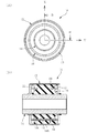
図6はその一例を示している。
同図において200は防振ブッシュを、202は金属製の剛性の外筒を、204は同じく金属製の剛性の内筒を、また206はそれら外筒202と内筒204との間に配されたゴム弾性体を示している。
【0005】
この例においてゴム弾性体206は外周面及び内周面が、外筒202及び内筒204にそれぞれ一体に加硫接着されている。
即ちこの例の防振ブッシュ200は内,外筒接着タイプの防振ブッシュである。
【0006】
この例の防振ブッシュ200においては、一対の中間板208が軸直角方向に互いに対向するようにして(図7参照)、ゴム弾性体206内部に埋設されている。
ここで一対の中間板208は金属製の剛性の部材で、外筒202の内周面及び内筒204の外周面に沿った湾曲形状をなしている。
詳しくは、ここでは外筒202及び内筒204はそれぞれ円筒形状をなしており、これに対応して一対の中間板208はそれぞれが円弧形状をなしていて、ゴム弾性体206の肉厚方向(軸直角方向)の略中間部分に埋設されている。
【0007】
このように剛性の中間板をゴム弾性体の内部に設けて、軸直角方向におけるある一方向のばね特性を、90°異なった方向のばね特性よりも硬くして成る防振ブッシュは、例えば下記特許文献1,特許文献2にも開示されている。
【0008】
例えば下記特許文献1には、その図1においてゴム弾性体3の内部に中間板4を設けた点が開示されている。
また下記特許文献2においても、その図2及び図3にゴム弾性体26の内部に中間板28を設けた点が開示されている。
【0009】
【特許文献1】
特許第3079154号公報
【特許文献2】
特開2002−89601号公報
【0010】
【発明が解決しようとする課題】
特許文献1,特許文献2に開示のものも含めてこの種従来の防振ブッシュは、何れも中間部材が2分割(2ピース)式のものであり、この場合防振ブッシュを構成する剛性部品の部品点数が多くなるとともに製造工数が複雑化し、また防振ブッシュを自動機で製造することが難しくなり、これに伴ってその製造コストも高くなるなどの問題があった。
【0011】
【課題を解決するための手段】
本発明の防振ブッシュはこのような課題を解決するために案出されたものである。
而して請求項1のものは、剛性の外筒及び内筒と、それら外筒及び内筒間に配置されたゴム弾性体と、該外筒の内周面及び該内筒の外周面に沿った湾曲形状をなし、該ゴム弾性体の内部に埋設された剛性の中間板とを有する防振ブッシュにおいて、前記中間板を全周に繋がった一体のリング形状となすとともに該中間板に、軸直角方向において互いに対向する一対の開口窓部を該中間板を板厚方向に貫通する状態で設けたことを特徴とする。
【0012】
請求項2のものは、請求項1において、前記開口窓部は軸方向の中央部に設けてあり、開口外周が閉じた形態の閉形状のものであることを特徴とする。
【0013】
請求項3のものは、請求項1,2の何れかにおいて、前記ゴム弾性体における前記開口窓部より外周側の部分若しくは内周側の部分又はその両方が、該開口窓部の軸方向長よりも短くされていることを特徴とする。
【0014】
請求項4のものは、請求項1〜3の何れかにおいて、前記中間板は軸方向の端部が前記ゴム弾性体から露出して突き出しており、該突き出した端部に対して、前記ゴム弾性体の内部に埋った部分の全体若しくは一部の板厚が厚く又は薄くしてあることを特徴とする。
【0015】
請求項5のものは、請求項1〜4の何れかにおいて、前記ゴム弾性体は前記外筒及び内筒に一体に加硫接着されていることを特徴とする。
【0016】
【作用及び発明の効果】
上記のように本発明は、中間板を全周に繋がった一体のリング形状となすとともに、軸直角方向において互いに対向する一対の開口窓部を、中間板を貫通する状態で設けたものである。
この場合、リング形状をなす中間板の開口窓部を、相対的にばね特性を柔らかくしたい方向の側に配置し、また非開口部を相対的にばね特性を硬くしたい方向の側に配置しておくことで、軸直角方向におけるある一方向と他の方向とでばね特性を異ならせること、即ちばね特性に異方性を持たせることができる。
またその開口窓部の大きさを変更することで、上記柔らかい側のばね特性を容易に変化させることができる。
【0017】
本発明によれば、従来2ピースであった中間板を1ピース、即ち単一の部品として構成することができ、これにより防振ブッシュを構成する剛性部品の部品点数を少なくすることができる。
また防振ブッシュの成形金型への中間板のセット作業も容易となるとともに成形金型の構造も単純化でき、更には自動機による防振ブッシュ製造の自動化を図ることも容易となり、防振ブッシュ製造の所要コストを低減することが可能となる。
【0018】
ここで上記中間板における開口窓部は、その軸方向の中央部に設け、開口外周を閉じた形態の閉形状となしておくことができる(請求項2)。
【0019】
本発明においては、ゴム弾性体における上記開口窓部より外周側の部分若しくは内周側の部分又はその両方を、開口窓部の軸方向長よりも短くしておくこと、厳密にはそれら外周側の部分,内周側の部分の軸方向長の最も短い部分の寸法を、開口窓部の軸方方向長よりも短くしておくことができる(請求項3)。
このようにすることで、開口窓部を配置した側の軸直角方向のばね特性を更に効果的に柔らかくすることができ、硬い側のばね特性と柔らかい側のばね特性とのばね比を更に大きくすることができる。
【0020】
次に請求項4は、上記中間板の軸方向の端部をゴム弾性体から露出して突き出させ、そしてその突き出した端部に対して、ゴム弾性体の内部に埋った部分の全体若しくは一部の板厚を厚く又は薄くしたものである。
【0021】
中間板の、ゴム弾性体内部に埋った部分の板厚はゴム弾性体のばね特性、即ち防振ブッシュのばね特性を左右する。詳しくは板厚が厚ければばね特性は硬いものとなり、逆に板厚が薄ければばね特性は柔らかいものとなる。
従ってゴム弾性体内部に埋っている部分の板厚を適宜厚く又は薄くすることによって、ばね特性を所望のばね特性に容易に調整,チューニングすることができる。
【0022】
一方でこの中間板は、軸方向の端部即ちゴム弾性体から外部に突き出した部分の厚みをほぼ一定に保持しておくことができ、この場合同じ成形金型を用いながら、ゴム弾性体内部に埋まっている中間板の板厚を変更して、様々に異なったばね特性を有する防振ゴムブッシュを成形することができる。
即ち種々異なったばね特性を有する防振ゴムブッシュを、同一の成形金型を用いて成形することが可能となる。
【0023】
ここで中間板は樹脂成形品,アルミニウム成形品で構成しておくことができる。この場合において樹脂成形品としては、強度上の面から硬質の樹脂が好ましく、例えばかかる硬質の樹脂材として、ガラス繊維入りポリアミド66(PA66)等が用いられる。
これら樹脂成形品,アルミニウム成形品にて中間板を構成した場合、その厚みをゴム弾性体から外部に突き出した部分と、ゴム弾性体内部に埋る部分とで容易に異ならせることができる。
【0024】
また中間板をこのような樹脂成形品,アルミニウム成形品で構成した場合次のような利点も得られる。
即ち中間板を金属製とした場合、開口窓部の内周縁に沿った角部を削って面取加工するが、その際にどうしてもエッジが残ってしまう。
而してそのようなエッジが残ると、そのエッジ部分がゴム弾性体の亀裂の起点となり、耐久性を低下せしめる要因となる。
しかるに中間板を樹脂成形品,アルミニウム成形品とした場合、予め角部を面取形状で成形しておくことができ、上記のようなエッジの発生を防止してゴム弾性体の亀裂発生を抑止し、ゴム弾性体の耐久寿命、即ち防振ブッシュの耐久寿命を長くすることができる。
【0025】
本発明は特に内,外筒接着タイプの防振ブッシュ、詳しくは外筒及び内筒に対してゴム弾性体が一体に加硫接着されたタイプの防振ブッシュに好適に適用することができる(請求項5)。
【0026】
【実施例】
次に本発明の実施例を図面に基づいて詳しく説明する。
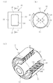
図1及び図2において、10は本例の防振ブッシュで、円筒形状をなす金属製の剛性の外筒12と、同じく円筒形状をなす金属製の剛性の内筒14と、それらの間に配されたゴム弾性体16とを有している。
【0027】
ゴム弾性体16は全周に連続的に繋がった円筒形状をなしており、その外周面,内周面がそれぞれ外筒12の内周面,内筒14の外周面に加硫接着により一体に固着されている。
即ちこの例の防振ブッシュ10はゴム弾性体16が内筒14,外筒12に接着された内,外筒接着タイプのものである。
【0028】
ゴム弾性体16の内部には、剛性の中間板18が埋設されている。ここで中間板18は、ゴム弾性体16に一体に加硫接着されている。
中間板18は、図3に示しているように周方向に連続に繋がった一体のリング形状(ここでは円筒形状)をなしており、軸直角方向において互いに対向する一対の開口窓部20が、中間板18を板厚方向に貫通する状態で設けられている。
これら一対の開口窓部20は、同図に示しているようにそれぞれが単一の開口部として形成されている。
【0029】
一対の開口窓部20は、それぞれ中間板18の軸方向の中央部に設けてあり、開口外周が閉じた形態の閉形状で且つ平面形状が矩形状に形成されている。
つまり本例の防振ブッシュ10における中間板18は、従来2ピースとされていた一対の円弧形状をなす中間板に相当する非開口部24が、軸方向両端部のブリッジ部22で互いに連結された形態をなしている。
【0030】
図1(B)及び図2(C)に示しているように、ゴム弾性体16は中間板18の開口窓部20の部分において、中間板18より内周側のゴム部16Aと外周側のゴム部16Bとが内外方向(軸直角方向)に繋がっている。
【0031】
また図1(B)及び図2(C)に示しているように、中間板18は軸方向の一端側と他端側とがゴム弾性体16から露出し突き出した状態でゴム弾性体16内部に埋設されている。
このようにすることにより、剛性部品である外筒12,内筒14及び中間板18を成形金型にセットした状態でゴム弾性体16を加硫成形する際、中間板18を成形金型に容易にセットし且つ位置決状態に保持させることができる。
【0032】
かかる本例の防振ブッシュ10の場合、それぞれ軸直角方向且つ互いに90°をなす図1(A)及び図3のX方向とY方向とでばね特性を異ならせることができる。
具体的には、開口窓部20を配置した側のX方向においてばね特性を柔らかく、また非開口部24を位置させた側のY方向のばね特性を硬くすることができる。即ち軸直角方向においてばね特性に異方性を持たせることができる。
【0033】
但しX方向とY方向とでばね特性を効果的に異ならせるためには、開口窓部20の開口面積をある程度大きくしておくことが必要がある。
この意味において、本例では開口窓部20の図2(B)の周長L、具体的にはその開口窓部20の中心O回りの中心角θを30〜150°の範囲としておくことが望ましい。
その範囲内で開口窓部20の大きさを様々に変化させることで、X方向のばね特性を種々変化させることができる。
【0034】
かかる本例によれば、従来2ピースであった中間板を1ピース、即ち単一の部品として構成することができ、これにより防振ブッシュ10を構成する剛性部品の部品点数を少なくすることができる。
また防振ブッシュの成形金型への中間板18のセット作業も容易となるとともに金型の構造も単純化でき、更には防振ブッシュ10製造の自動機による自動化を図ることも容易となり、防振ブッシュ10製造の所要コストを低減することが可能となる。
【0035】
図4は本発明の他の実施例を示している。
この例は、中間板18における開口窓部20の軸方向寸法Aを上記実施例よりも僅かに大きくする一方で、ゴム弾性体16における外周側のゴム部16Bの軸方向寸法B(厳密には軸方向長が最も短くなる部分の寸法B)を上記実施例よりも小さくし、ゴム部16Bの寸法Bを開口窓部20の寸法Aよりも小寸法となした例である。
【0036】
このようになした場合、図1におけるX方向のばね特性をより一段と柔らかくすることができる。
即ちX方向のばね特性とY方向のばね特性との比率であるばね比を上記実施例よりも更に大きくすることができる。
【0037】
尚、ここでは外周側のゴム部16Bのみ開口窓部20の寸法Aよりも小寸法としているが、これに代えて内周側のゴム部16Aのみの軸方向寸法を開口窓部20の寸法Aよりも小寸法となすこと、更にはゴム部16A,16Bの何れも開口窓部20の寸法Aよりも小寸法となしておくこともできる。
そのようにすれば、X方向のばね特性を更に一段と柔らかくすることができる。
【0038】
図5は本発明の更に他の実施例を示している。
この例は、中間板18におけるブリッジ部22及び非開口部24のブリッジ部22に対応する部分、詳しくは軸方向両端部におけるブリッジ部22と同等長部分を上記第1の実施例と同等板厚に保持しつつ、他の部分の板厚を変化させた例である。
【0039】
即ちゴム弾性体16から軸方向に露出して外部に突き出す部分の板厚を同等に保持し、ゴム弾性体16内部に埋まり込む部分の板厚を変化させた例である。
このうち図5(A)の例は、ゴム弾性体16内部に埋まり込む部分の板厚を厚くした例を、また(B)は逆に薄くした例をそれぞれ示している。
【0040】
中間板18の、ゴム弾性体16内部に埋った部分の板厚は、ゴム弾性体16のばね特性、即ち防振ブッシュ10のばね特性を左右するものであり、図5(A)に従ってその部分の板厚を厚くすれば、ばね特性は硬いものとなる。即ち開口窓部20を設けた側とは直角方向のY方向のばね特性が硬いものとなる。
逆に(B)の例に従って板厚を薄くすれば、同じくY方向のばね特性は柔らかいものとなる。
従ってこの実施例に従い、ゴム弾性体16内部に埋っている部分の板厚を厚く又は薄くすることによって、Y方向のばね特性を所望のばね特性に容易に調整しチューニングすることができる。
【0041】
一方において本例では、ゴム弾性体16から露出して軸方向に突き出した部分、即ち成形金型によって保持される部分の板厚は上記第1の実施例と同じ板厚に保持しているから、第1の実施例と同じ成形金型を用いながら、ゴム弾性体16内部に埋っている部分の板厚の変更により、様々に異なったばね特性を有する防振ブッシュ10を成形することが可能となる。
【0042】
この場合において中間板18は樹脂成形品,アルミニウム成形品で構成しておくことができる。この樹脂成形品としては、硬質の樹脂を用いることができ、特に好ましくはガラス繊維入りポリアミド66(PA66)を用いることができる。
これら樹脂成形品,アルミニウム成形品にて中間板18を構成した場合、その厚みを軸方向の両端部とそれらの間の部分とで容易に異ならせることができる。即ち板厚の異なった中間板18を容易に得ることができる。
【0043】
また中間板18をこのような樹脂成形品,アルミニウム成形品で構成した場合、次の利点も得られる。
即ち中間板18を金属製とした場合、開口窓部20の内周縁に沿った角部を削って面取加工するが、その際にエッジが残ってしまう。
そしてそのようなエッジが残ると、そのエッジ部分がゴム弾性体16の亀裂の起点となり、耐久性を低下せしめる要因となる。
【0044】
しかるに本例に従って中間板18を樹脂成形品,アルミニウム成形品で構成した場合、予め角部を面取形状で成形しておくことができ、上記のようなエッジの発生を防止してゴム弾性体16の亀裂発生を抑止し、ゴム弾性体16の耐久寿命即ち防振ブッシュ10の耐久寿命を長くすることができる。
【0045】
以上本発明の実施例を詳述したがこれはあくまで一例示であり、本発明は他の様々な形態の防振ブッシュに対しても適用可能であるなど、本発明はその趣旨を逸脱しない範囲において種々変更を加えた形態で構成可能である。
【図面の簡単な説明】
【図1】(A):本発明の一実施例である防振ブッシュの正面図である。
(B):(A)におけるB−B断面図である。
【図2】(A):同実施例の防振ブッシュにおける中間板の正面図である。
(B):(A)におけるB−B断面図である。
(C):同実施例の防振ブッシュの一部切欠斜視図である。
【図3】同実施例の防振ブッシュにおける外筒,内筒,中間板を分離して示す斜視図である。
【図4】(A):本発明の他の実施例における中間板の斜視図である。
(B):同他の実施例の防振ブッシュの側面断面図である。
【図5】(A):本発明の他の実施例における中間板の要部拡大図である。
(B):更に他の実施例における中間板の要部拡大図である。
【図6】(A):従来用いられている防振ブッシュの正面図である。
(B):(A)のB−B断面図である。
【図7】図6における防振ブッシュの中間板を単体で示す斜視図である。
【符号の説明】
10 防振ブッシュ
12 外筒
14 内筒
16 ゴム弾性体
18 中間板
20 開口窓部[0001]
TECHNICAL FIELD OF THE INVENTION
The present invention relates to a cylindrical vibration isolating bush in which a rubber elastic body is disposed between a rigid outer cylinder and an inner cylinder, and more specifically, a form in which an intermediate plate for hardening spring characteristics is inserted inside the rubber elastic body. About things.
[0002]
[Prior art]
2. Description of the Related Art Conventionally, a cylindrical vibration-isolating bush having a rigid outer cylinder and an inner cylinder made of metal and a rubber elastic body disposed therebetween has been widely used as a suspension bush or the like.
[0003]
In this anti-vibration bush, there is a case where it is desired to make the spring characteristic in one direction in the direction perpendicular to the axis harder than the spring characteristic in another direction, for example, a direction different by 90 °. 2. Description of the Related Art A method of embedding a rigid intermediate plate having a curved shape along the inner peripheral surface of an outer cylinder and the outer peripheral surface of an inner cylinder in a certain direction in a rubber elastic body is conventionally known.
[0004]
FIG. 6 shows an example.
In the figure, 200 is an anti-vibration bush, 202 is a rigid outer cylinder made of metal, 204 is a rigid inner cylinder made of the same metal, and 206 is arranged between the
[0005]
In this example, the outer peripheral surface and the inner peripheral surface of the rubber
That is, the
[0006]
In the
Here, the pair of
Specifically, here, the
[0007]
By providing the rigid intermediate plate inside the rubber elastic body in this way, a vibration-isolating bush formed by making the spring characteristic in one direction in the direction perpendicular to the axis harder than the spring characteristic in a direction different by 90 ° is, for example, It is also disclosed in Patent Documents 1 and 2.
[0008]
For example, Patent Document 1 below discloses that an intermediate plate 4 is provided inside a rubber elastic body 3 in FIG.
Patent Document 2 below discloses that an intermediate plate 28 is provided inside a rubber elastic body 26 in FIGS. 2 and 3.
[0009]
[Patent Document 1]
Japanese Patent No. 3079154 [Patent Document 2]
JP-A-2002-89601
[Problems to be solved by the invention]
In this type of conventional vibration-isolating bush, including those disclosed in Patent Literature 1 and Patent Literature 2, the intermediate member is of a two-part (two-piece) type, and in this case, a rigid component constituting the vibration-isolating bush As the number of parts increases, the number of manufacturing steps becomes complicated, and it becomes difficult to manufacture an anti-vibration bush by an automatic machine. As a result, the manufacturing cost increases.
[0011]
[Means for Solving the Problems]
The anti-vibration bush of the present invention has been devised to solve such a problem.
According to the first aspect, a rigid outer cylinder and an inner cylinder, a rubber elastic body disposed between the outer cylinder and the inner cylinder, an inner peripheral surface of the outer cylinder and an outer peripheral surface of the inner cylinder are provided. In a vibration-isolating bush having a curved shape along with a rigid intermediate plate buried inside the rubber elastic body, the intermediate plate is formed into an integral ring shape connected to the entire circumference, and the intermediate plate is A pair of opening windows facing each other in a direction perpendicular to the axis is provided so as to penetrate the intermediate plate in the plate thickness direction.
[0012]
According to a second aspect of the present invention, in the first aspect, the opening window portion is provided at a central portion in the axial direction, and has a closed shape in which an outer periphery of the opening is closed.
[0013]
According to a third aspect of the present invention, in any one of the first and second aspects, a portion of the rubber elastic body on an outer peripheral side and / or an inner peripheral side of the opening window portion has an axial length of the opening window portion. It is characterized in that it is shorter than the above.
[0014]
According to a fourth aspect of the present invention, in any one of the first to third aspects, the intermediate plate has an axial end exposed and protruded from the rubber elastic body. The whole or a part of the portion buried in the elastic body is thick or thin.
[0015]
According to a fifth aspect, in any one of the first to fourth aspects, the rubber elastic body is integrally vulcanized and bonded to the outer cylinder and the inner cylinder.
[0016]
[Action and effect of the invention]
As described above, in the present invention, the intermediate plate is formed into an integral ring shape that is connected to the entire circumference, and a pair of opening windows facing each other in a direction perpendicular to the axis is provided so as to penetrate the intermediate plate. .
In this case, the opening window portion of the ring-shaped intermediate plate is disposed on the side in the direction in which the spring characteristics are relatively soft, and the non-opening portion is disposed in the direction in which the spring characteristics are relatively hard. By doing so, it is possible to make the spring characteristics different between one direction and the other direction in the direction perpendicular to the axis, that is, to give the spring characteristics anisotropy.
By changing the size of the opening window, the spring characteristic on the soft side can be easily changed.
[0017]
According to the present invention, the intermediate plate, which has conventionally been two pieces, can be configured as one piece, that is, a single part, whereby the number of rigid parts constituting the vibration isolating bush can be reduced.
In addition, the work of setting the intermediate plate in the molding die of the vibration-isolating bush becomes easy, and the structure of the molding die can be simplified. Further, it is easy to automate the manufacture of the vibration-isolating bush by an automatic machine. It is possible to reduce the cost required for manufacturing the bush.
[0018]
Here, the opening window portion of the intermediate plate may be provided at a central portion in the axial direction, and may have a closed shape in which the outer periphery of the opening is closed (claim 2).
[0019]
In the present invention, the portion of the rubber elastic body on the outer peripheral side and / or the inner peripheral side of the opening window is shorter than the axial length of the opening window. The dimension of the shortest portion in the axial direction of the portion and the portion on the inner peripheral side can be made shorter than the axial length of the opening window portion.
By doing so, the spring characteristic in the direction perpendicular to the axis on the side where the opening window is arranged can be more effectively softened, and the spring ratio between the hard side spring characteristic and the soft side spring characteristic can be further increased. can do.
[0020]
Next, the axial end of the intermediate plate is exposed and protruded from the rubber elastic body, and the protruding end is entirely or partially embedded in the rubber elastic body. The thickness of the part is made thicker or thinner.
[0021]
The thickness of the portion of the intermediate plate buried in the rubber elastic body affects the spring characteristics of the rubber elastic body, that is, the spring characteristics of the vibration isolating bush. More specifically, the spring characteristics become harder when the plate thickness is thicker, while the spring characteristics become softer when the plate thickness is thinner.
Therefore, the spring characteristics can be easily adjusted and tuned to the desired spring characteristics by appropriately increasing or decreasing the thickness of the portion embedded in the rubber elastic body.
[0022]
On the other hand, this intermediate plate can keep the thickness of the end portion in the axial direction, that is, the portion protruding outside from the rubber elastic body, almost constant. In this case, while using the same molding die, By changing the thickness of the intermediate plate buried in the rubber, a vibration-proof rubber bush having various different spring characteristics can be formed.
That is, it is possible to mold vibration-proof rubber bushes having various spring characteristics using the same molding die.
[0023]
Here, the intermediate plate can be formed of a resin molded product or an aluminum molded product. In this case, the resin molded product is preferably a hard resin in terms of strength. For example, polyamide 66 (PA66) containing glass fiber is used as the hard resin material.
When the intermediate plate is made of these resin molded product and aluminum molded product, the thickness of the intermediate plate can be easily made different between a portion protruding outside from the rubber elastic body and a portion buried inside the rubber elastic body.
[0024]
When the intermediate plate is made of such a resin molded product or aluminum molded product, the following advantages can be obtained.
In other words, when the intermediate plate is made of metal, the corners along the inner peripheral edge of the opening window are cut off and chamfered, but the edges remain in that case.
If such an edge remains, the edge portion becomes a starting point of a crack in the rubber elastic body, which is a factor of reducing durability.
However, when the intermediate plate is made of a resin molded product or an aluminum molded product, the corners can be formed in a chamfered shape in advance, thereby preventing the occurrence of the edges described above and suppressing the cracking of the rubber elastic body. In addition, the durable life of the rubber elastic body, that is, the durable life of the vibration isolating bush can be extended.
[0025]
The present invention can be particularly suitably applied to an inner and outer cylinder-attached type vibration-isolating bush, more specifically, a type of vibration-isolating bush in which a rubber elastic body is integrally vulcanized and bonded to an outer cylinder and an inner cylinder ( Claim 5).
[0026]
【Example】
Next, embodiments of the present invention will be described in detail with reference to the drawings.
1 and 2,
[0027]
The rubber
That is, the
[0028]
A rigid
The
Each of the pair of opening
[0029]
Each of the pair of opening
That is, in the
[0030]
As shown in FIGS. 1B and 2C, the rubber
[0031]
Further, as shown in FIGS. 1B and 2C, the
In this manner, when the rubber
[0032]
In the case of the
Specifically, it is possible to soften the spring characteristics in the X direction on the side where the
[0033]
However, in order to effectively make the spring characteristics different between the X direction and the Y direction, it is necessary to increase the opening area of the opening
In this sense, in this example, the peripheral length L of the opening
By variously changing the size of the
[0034]
According to this example, the intermediate plate, which has been conventionally two pieces, can be configured as one piece, that is, a single part, whereby the number of rigid parts constituting the
Also, the work of setting the
[0035]
FIG. 4 shows another embodiment of the present invention.
In this example, while the axial dimension A of the opening
[0036]
In such a case, the spring characteristic in the X direction in FIG. 1 can be further softened.
That is, the spring ratio, which is the ratio between the spring characteristics in the X direction and the spring characteristics in the Y direction, can be further increased as compared with the above embodiment.
[0037]
Note that, here, only the
By doing so, the spring characteristics in the X direction can be further softened.
[0038]
FIG. 5 shows still another embodiment of the present invention.
In this example, a portion corresponding to the
[0039]
That is, this is an example in which the thickness of the portion exposed in the axial direction from the rubber
5A shows an example in which the thickness of the portion embedded in the rubber
[0040]
The thickness of the portion of the
Conversely, if the plate thickness is reduced according to the example of (B), the spring characteristics in the Y direction also become soft.
Therefore, according to this embodiment, by increasing or decreasing the thickness of the portion embedded in the rubber
[0041]
On the other hand, in this embodiment, the thickness of the portion exposed from the rubber
[0042]
In this case, the
When the
[0043]
When the
That is, when the
If such an edge remains, the edge portion becomes a starting point of a crack in the rubber
[0044]
However, when the
[0045]
Although the embodiment of the present invention has been described in detail above, this is merely an example, and the present invention can be applied to other various forms of anti-vibration bushes. Can be configured in variously modified forms.
[Brief description of the drawings]
FIG. 1A is a front view of an anti-vibration bush according to an embodiment of the present invention.
(B): It is BB sectional drawing in (A).
FIG. 2A is a front view of an intermediate plate in the vibration isolating bush of the embodiment.
(B): It is BB sectional drawing in (A).
(C): It is a partially cutaway perspective view of the vibration-proof bush of the example.
FIG. 3 is a perspective view showing an outer cylinder, an inner cylinder, and an intermediate plate in the vibration isolating bush of the embodiment in a separated state.
FIG. 4A is a perspective view of an intermediate plate according to another embodiment of the present invention.
(B): It is a side sectional view of the vibration-proof bush of the other example.
FIG. 5A is an enlarged view of a main part of an intermediate plate according to another embodiment of the present invention.
(B): It is the principal part enlarged view of the intermediate board in further another Example.
FIG. 6A is a front view of a conventionally used anti-vibration bush.
(B): It is BB sectional drawing of (A).
FIG. 7 is a perspective view showing an intermediate plate of the vibration isolating bush in FIG. 6 as a single body.
[Explanation of symbols]
DESCRIPTION OF
Claims (5)
前記中間板を全周に繋がった一体のリング形状となすとともに該中間板に、軸直角方向において互いに対向する一対の開口窓部を該中間板を板厚方向に貫通する状態で設けたことを特徴とする防振ブッシュ。A rigid outer cylinder and an inner cylinder, a rubber elastic body disposed between the outer cylinder and the inner cylinder, and a curved shape along the inner peripheral surface of the outer cylinder and the outer peripheral surface of the inner cylinder; A vibration isolating bush having a rigid intermediate plate embedded in the body,
The intermediate plate has an integral ring shape connected to the entire circumference, and the intermediate plate has a pair of opening windows facing each other in a direction perpendicular to the axis so as to penetrate the intermediate plate in the thickness direction. Characteristic anti-vibration bush.
Priority Applications (1)
| Application Number | Priority Date | Filing Date | Title |
|---|---|---|---|
| JP2003055014A JP2004263782A (en) | 2003-02-28 | 2003-02-28 | Anti-vibration bushing |
Applications Claiming Priority (1)
| Application Number | Priority Date | Filing Date | Title |
|---|---|---|---|
| JP2003055014A JP2004263782A (en) | 2003-02-28 | 2003-02-28 | Anti-vibration bushing |
Publications (1)
| Publication Number | Publication Date |
|---|---|
| JP2004263782A true JP2004263782A (en) | 2004-09-24 |
Family
ID=33119140
Family Applications (1)
| Application Number | Title | Priority Date | Filing Date |
|---|---|---|---|
| JP2003055014A Pending JP2004263782A (en) | 2003-02-28 | 2003-02-28 | Anti-vibration bushing |
Country Status (1)
| Country | Link |
|---|---|
| JP (1) | JP2004263782A (en) |
Cited By (7)
| Publication number | Priority date | Publication date | Assignee | Title |
|---|---|---|---|---|
| JP2006123818A (en) * | 2004-10-29 | 2006-05-18 | Tokai Rubber Ind Ltd | Stabilizer bush |
| JP2008256077A (en) * | 2007-04-04 | 2008-10-23 | Toyo Tire & Rubber Co Ltd | Anti-vibration bushing |
| JP2008267535A (en) * | 2007-04-23 | 2008-11-06 | Toyo Tire & Rubber Co Ltd | Vibration absorbing bush |
| JP2009002492A (en) * | 2007-06-25 | 2009-01-08 | Kurashiki Kako Co Ltd | Inner member |
| CN102537166A (en) * | 2012-02-08 | 2012-07-04 | 上海骆氏减震件有限公司 | Suspension lining and manufacturing method thereof |
| KR20150004587A (en) * | 2013-07-03 | 2015-01-13 | 현대모비스 주식회사 | Hydro-geometry bush |
| JP2018079752A (en) * | 2016-11-15 | 2018-05-24 | 東洋ゴム工業株式会社 | Stabilizer bush |
-
2003
- 2003-02-28 JP JP2003055014A patent/JP2004263782A/en active Pending
Cited By (9)
| Publication number | Priority date | Publication date | Assignee | Title |
|---|---|---|---|---|
| JP2006123818A (en) * | 2004-10-29 | 2006-05-18 | Tokai Rubber Ind Ltd | Stabilizer bush |
| JP4560376B2 (en) * | 2004-10-29 | 2010-10-13 | 東海ゴム工業株式会社 | Stabilizer bush |
| JP2008256077A (en) * | 2007-04-04 | 2008-10-23 | Toyo Tire & Rubber Co Ltd | Anti-vibration bushing |
| JP2008267535A (en) * | 2007-04-23 | 2008-11-06 | Toyo Tire & Rubber Co Ltd | Vibration absorbing bush |
| JP2009002492A (en) * | 2007-06-25 | 2009-01-08 | Kurashiki Kako Co Ltd | Inner member |
| CN102537166A (en) * | 2012-02-08 | 2012-07-04 | 上海骆氏减震件有限公司 | Suspension lining and manufacturing method thereof |
| KR20150004587A (en) * | 2013-07-03 | 2015-01-13 | 현대모비스 주식회사 | Hydro-geometry bush |
| KR102063725B1 (en) * | 2013-07-03 | 2020-01-08 | 현대모비스 주식회사 | Hydro-geometry bush |
| JP2018079752A (en) * | 2016-11-15 | 2018-05-24 | 東洋ゴム工業株式会社 | Stabilizer bush |
Similar Documents
| Publication | Publication Date | Title |
|---|---|---|
| JP3541793B2 (en) | Cylindrical dynamic damper | |
| WO2014069441A1 (en) | Vibration-damping device | |
| KR20170069758A (en) | Structure of Mounting bracket | |
| JP2004263782A (en) | Anti-vibration bushing | |
| JP2002098193A (en) | Cylindrical dynamic damper | |
| JP2003343625A (en) | Anti-vibration bush | |
| JP3680575B2 (en) | Rubber bush and manufacturing method thereof | |
| CN111102311B (en) | Vibration-proof bush | |
| JPH11182598A (en) | Vibration control device | |
| JP2006118561A (en) | Method of manufacturing stabilizer bar with rubber bush | |
| JP2002039394A (en) | Gasket with filter | |
| JP2002276714A (en) | Vibration isolation device | |
| JP3543674B2 (en) | Anti-vibration bush | |
| JP2007064301A (en) | Rubber vibration isolator member | |
| JP6824715B2 (en) | Dynamic damper | |
| US20190301556A1 (en) | Method for manufacturing vibration isolation apparatus | |
| JPH09210107A (en) | Vibration control bushing | |
| JP4413028B2 (en) | Vibration isolator and manufacturing method thereof | |
| JP2003269509A (en) | Vibration control bush | |
| JPH0343083B2 (en) | ||
| JP2010060023A (en) | Vibration damping bushing | |
| JPH0293134A (en) | Vibration isolating bush | |
| JPH02256934A (en) | Cylindrical vibration isolating rubber | |
| JP3456286B2 (en) | Cylindrical anti-vibration mount | |
| JPH0425628A (en) | Bush type oscillation proof rubber |
Legal Events
| Date | Code | Title | Description |
|---|---|---|---|
| A621 | Written request for application examination |
Free format text: JAPANESE INTERMEDIATE CODE: A621 Effective date: 20051117 |
|
| A977 | Report on retrieval |
Free format text: JAPANESE INTERMEDIATE CODE: A971007 Effective date: 20080403 |
|
| A131 | Notification of reasons for refusal |
Effective date: 20080520 Free format text: JAPANESE INTERMEDIATE CODE: A131 |
|
| A02 | Decision of refusal |
Free format text: JAPANESE INTERMEDIATE CODE: A02 Effective date: 20080930 |