JP2004246306A - Manufacturing method of light amount adjusting member - Google Patents
Manufacturing method of light amount adjusting member Download PDFInfo
- Publication number
- JP2004246306A JP2004246306A JP2003039391A JP2003039391A JP2004246306A JP 2004246306 A JP2004246306 A JP 2004246306A JP 2003039391 A JP2003039391 A JP 2003039391A JP 2003039391 A JP2003039391 A JP 2003039391A JP 2004246306 A JP2004246306 A JP 2004246306A
- Authority
- JP
- Japan
- Prior art keywords
- adjusting member
- light amount
- amount adjusting
- light
- light quantity
- Prior art date
- Legal status (The legal status is an assumption and is not a legal conclusion. Google has not performed a legal analysis and makes no representation as to the accuracy of the status listed.)
- Granted
Links
Images


Landscapes
- Optical Elements Other Than Lenses (AREA)
- Diaphragms For Cameras (AREA)
- Blocking Light For Cameras (AREA)
Abstract
Description
【0001】
【発明の属する技術分野】
本発明は、デジタルカメラ、ビデオカメラ等の光学機器等、或いは電子写真方式記録装置等の、多種多様な分野で有効に使用できる光量調節部材が簡便に得られる、光量調節部材の製造方法に関し、更には、該方法によって得られる優れた光量調節部材、該光量調節部材を用いた光量調節装置および撮影装置に関する。
【0002】
【従来の技術】
カメラ等の光学機器に用いられる結像(撮影)光学系には、一般に入射光束の光量を調節する光量調節装置、いわゆる絞り装置が内蔵されている。かかる絞り装置においては、複数の絞り羽根が所定面積の開口部を形成し、アクチュエータで該開口部の開口径を調節することで、開口部を通過する光束の量を調節している。しかし、該開口部の開口径を小さくするに従って、絞り羽根の端部で生ずる回折の影響が大きくなり、結像光学系の結像性能が低下する。これに対し、かかる欠点を回避するために、上記絞り羽根の一部に光量調節部材としてのフィルタを設け、開口径を小さくする代わりに光学フィルタで、開口部を通過する光束の量(光量)を減衰させる技術が知られている。このような目的に用いられる光学フィルタには、光の散乱、屈折異常、分光透過率偏差等の光学的欠陥が少ないものであることが要求される。
【0003】
従来より、上記の光量調節部材として一般的に使用されているのは、光透過性のフィルム形成材料中に光を吸収する顔料や染料等の色材を混合して練り込んで着色フィルムとしたタイプのものである。しかしながら、この方式によって製造される光量調節部材は高価であり、拡大している需要に対して要求されているコストダウンに十分に応えられるものではなかった。また、光透過性のフィルム材料中に色材を練り込んで着色フィルムとする方式では、連続的な、或いは段階的な濃度分布を有する(以下、「多濃度の」と呼ぶ)光量調節部材を製造することは著しく困難であるという問題もある。
【0004】
他に知られている光量調節部材の製造方法としては、銀塩フィルムを用いる方法があり、かかる方法によれば多濃度の光量調節部材を製造できる(例えば、特許文献1等参照)。しかし、この方法で得られた光量調節部材の場合には、フィルタに内在する銀粒子表面での光束の反射や、銀粒子端部を通過する光束の回折によって、該フィルタを通過した光線の直進性が損なわれて光学系の結像性能が低下する、といった銀塩フィルムを用いることによる特有の問題が生じる。
【0005】
また、蒸着法により、多濃度の光量調節部材を製造する方法についての提案もある(例えば、特許文献2等参照)。しかし、この方法の場合には、製造コストがかかり高価なものとなるのに加えて、濃度によって膜厚が変化するために、濃度の高いところと低いところで膜厚差が生じ、結果として光路差が生じて、解像力が低下するといった問題を生ずる。更に、この方式では、連続的な濃度分布を有するものを製造することは非常に困難であり、製造したとしても濃度分布が段階的に変化したものになる。
【0006】
また、先ず光によって褪色する有機色素をフィルム材料中に練り込み、得られたフィルムに部分的に高エネルギーの光を照射することで照射部分の有機色素を分解させ、これによって多濃度の光量調節部材を製造する方法についての提案もある(例えば、特許文献3等参照)。しかしながら、この方式では、使用可能な色材が、光によって褪色するものに限定されてしまうため、十分な光学的特性を有する製品を得ることが非常に困難である。更に、その煩雑な製法から、得られる製品が非常に高価なものになってしまうであろうことは容易に推測できる。
【0007】
更に、蒸着或いは写真製版等の印刷工程によって単一濃度の膜を網点状に形成し、網点パターンを場所によって変えることで、透過率が無段階に変わる光量調節部材としてのフィルタを製造する方法についての提案がある(例えば、特許文献4等参照)。しかしながら、かかる方法は、写真製版或いは蒸着で所定濃度の膜を形成するものであり、何れの工程を採用したとしても、装置が大型化し、高価であり、フィルタの製造コストが高くなってしまうという課題がある。
【0008】
【特許文献1】
特開平5−173004号公報
【特許文献2】
特開平10−133254号公報
【特許文献3】
特開平10−96971号公報
【特許文献4】
特開2000−352736号公報
【0009】
【発明が解決しようとする課題】
従って、本発明の目的は、上記した従来技術の課題を解決し、光学特性を十分に満足し得る光量調節部材を、製造コストが低く、歩留まりの高い簡便な操作によって経済的に製造することが可能な光量調節部材の製造方法を提供することにある。また、本発明の目的は、上記に加えて、特に、連続的な、或いは段階的な濃度分布を有する光量調節部材を簡便に得ることができる光量調節部材の製造方法を提供することにある。更に、本発明の目的は、上記した簡便な製造方法によって、光学特性を十分に満足できる光量調節部材を安価に簡便に製造することで、光量調節部材を具備する多種多様な光量調節装置及び撮影装置を、十分な光学特性を達成しつつ安価に提供することにある。
【0010】
【課題を解決するための手段】
上記の目的は、以下の本発明によって達成される。即ち、本発明の第1の態様は、[1]着色液を吸収し得る材料からなる層を有する透明基材を用意する工程と、該層に液体噴射記録法を用いて色材を含む着色液を付与し、特定の光学濃度をもつ光量調節領域を形成する工程とを有することを特徴とする光量調節部材の製造方法である。
【0011】
上記した本発明の第1の態様にかかる光量調節部材の製造方法の好ましい形態としては、下記の[2]〜[4]を挙げることができる。[2]前記光量調節領域が、連続的に或いは段階的に濃度分布を有するものとなるように着色液を付与する上記[1]に記載の光量調節部材の製造方法。[3]前記光量調節領域を形成する工程の後に、更に、前記光量調節領域表面上に透明の平坦化層を設ける工程を有する上記[1]または[2]に記載の光量調節部材の製造方法。[4]前記層上に着色液が付与されて形成される該着色液の1ドット面積が、前記光量調節領域の面積の20分の1以下となるように着色液を付与する上記[1]〜[3]のいずれかに記載の光量調節部材の製造方法。
【0012】
本発明の第2の態様は、[5]透明基材上に液体噴出記録方法を用いて透明樹脂材料及び色材を少なくとも含有する着色液を付与する工程と、該透明樹脂材料を硬化して、特定の光学濃度をもつ光量調節領域を形成する工程とを有することを特徴とする光量調節部材の製造方法である。
【0013】
上記した本発明の第2の態様にかかる光量調節部材の製造方法の好ましい形態としては、下記の[6]〜[9]を挙げることができる。[6]前記光量調節領域が、連続的に或いは段階的に濃度分布を有するものとなるように着色液を付与する上記[5]に記載の光量調節部材の製造方法。[7]前記光量調節領域を形成する工程の後に、光量調節領域表面上に透明の平坦化層を設ける工程を有する上記[5]または[6]に記載の光量調節部材の製造方法。[8]前記光量調節領域を形成する工程の後に、該光量調節領域表面を研磨する工程を有する上記[5]または[6]に記載の光量調節部材の製造方法。[9]前記透明基材上に着色液が付与されて形成される着色液の1ドット面積が、前記光量調節領域の面積の20分の1以下となるように着色液を付与する上記[5]〜[8]のいずれかに記載の光量調節部材の製造方法。
【0014】
本発明の別の実施態様としては、下記の[10]〜[12]を挙げることができる。[10]上記[1]〜[9]のいずれかに記載の光量調節部材の製造方法によって製造されたことを特徴とする光量調節部材。[11]所定の開口径を有する開口部を通過する光束の状態を調節するための光量調節装置において、前記光束に所定の透過率を与えるための第1の領域と、前記光束を遮断するための第2の領域を備え、且つ、前記第1の領域が、上記[10]に記載の光量調節部材からなることを特徴とする光量調節装置。[12]上記[11]に記載の光量調節装置と、被写体像を形成する撮影光学系と、形成した被写体像を光電変換する撮像手段と、上記光電変換された信号を記録する記録手段とを有し、且つ、上記光量調節装置が撮影光学系に配置されていることを特徴とする撮影装置。
【0015】
【発明の実施の形態】
以下に、本発明にかかる光量調節部材の製造方法の好ましい実施の形態を挙げて本発明を更に詳細に説明する。
<第1の態様>
本発明の第1の態様にかかる光量調節部材の製造方法は、着色液を吸収し得る材料からなる層を有する透明基材を用意する工程と、該基材の層に対して、液体噴射記録法により色材を含む着色液を付与して受容させて、光束の透過量を調節し得る、特定の光学濃度をもつ光量調節領域を形成する工程とを有することを特徴とするが、この場合に、透明基材に着色液を吸収し得る材料からなる層を形成する工程に引き続き、光量調節領域となる着色層を形成する工程を行なって、透明基材に、連続的に光量調節領域を形成するように構成してもよい。以下、透明基材上に着色液を吸収し得る材料からなる層を形成する場合に使用するコーティング方法、更には、この場合に使用する材料について説明する。
【0016】
透明基材上に着色液を受容し得る層を形成するためには、先ず、後述する材料を必要により他の添加剤と共に、水、或いはアルコール、多価アルコール類、又は他の適当な有機溶媒に溶解または分散し、塗工液を調製する。次いで得られた塗工液を、例えば、ロールコーター法、ブレードコーター法、エアナイフコーター法、ゲートロールコーター法、バーコーター法、サイズプレス法、スプレーコート法、グラビアコーター法、カーテンコーター法、スピンコート法等により基材表面に塗工する。その後、例えば、熱風乾燥炉、熱ドラム、ホットプレート等を用いて乾燥を行って、着色液を吸収・受容し得る受容層を形成する。
【0017】
本発明において用いることのできる透明基材としては、光量調節部材としての機械的強度及び光学的特性等の必要特性を有していれば、特に限られるものではない。例えば、ポリエチレンテレフタレート、ジアセテート、トリアセテート、セロハン、セルロイド、ポリカーボネート、ポリイミド、ポリビニルクロライド、ポリビニリデンクロライド、ポリアクリレート、ポリエチレン、ポリプロピレン等からなる透明フィルム基材を挙げることができる。また、上記必要特性を満たすものであれば、ガラス基材を使用することも可能である。
【0018】
また、上記のような透明基材上に設ける着色液を吸収し得る層を形成する場合の塗工液材料としては、該材料によって形成された層に着色液が吸収され、該着色液中の色材を受容し定着できるものであればよく、特に限られるものではない。例えば、このようなものとして、下記に挙げるような水溶性樹脂及び水分散性樹脂を好ましく用いることができる。
【0019】
水溶性樹脂としては、例えば、ポリビニルアルコール、及びアニオン変性ポリビニルアルコール、カチオン変性ポリビニルアルコール、アセタール変性ポリビニルアルコール等のポリビニルアルコールの変性物;水系ポリウレタン;ポリビニルピロリドン、及びビニルピロリドンと酢酸ビニル共重合体、ビニルピロリドンとジメチルアミノエチル・メタクリル酸の共重合体、4級化したビニルピロリドンとジメチルアミノエチル・メタクリル酸の共重合体、ビニルピロリドンとメタクリルアミドプロピル塩化トリメチルアンモニウム共重合体等のポリビニルピロリドンの変性物;カルボキシメチルセルロース、ヒドロキシエチルセルロース、ヒドロキシプロピルセルロース等のセルロース系水溶性樹脂、及びカチオン化ヒドロキシエチルセルロース等のセルロースの変性物;ポリエステル、ポリアクリル酸(エステル)、メラミン樹脂、或いはこれらの変性物、少なくともポリエステルとポリウレタンとを含むグラフト共重合体等の合成樹脂、また、アルブミン、ゼラチン、カゼイン、でんぷん、カチオン化でんぷん、アラビアゴム、アルギン酸ソーダ等の天然樹脂等を挙げることができる。
【0020】
また、水分散性樹脂としては、例えば、ポリ酢酸ビニル、エチレン−酢酸ビニル共重合体、ポリスチレン、スチレン−(メタ)アクリル酸エステル共重合体、(メタ)アクリル酸エステル系重合体、酢酸ビニル−(メタ)アクリル酸(エステル)共重合体、ポリ(メタ)アクリルアミド、(メタ)アクリルアミド系共重合体、スチレン−イソプレン共重合体、スチレン−ブタジエン共重合体、スチレン−プロピレン共重合体、ポリビニルエーテル、シリコーン−アクリル系共重合体等、多数列挙することができるが、勿論、本発明は、これらに限定されるものではない。
【0021】
また、上記の水溶性樹脂或いは水分散性樹脂をバインダーとし、これらの材料に、例えば、アルミナ水和物、シリカ、炭酸カルシウム等の顔料を混合させた隙間吸収タイプのものも、光学的特性を満たす範囲内で使用できる。
【0022】
更に、塗工液中には上記材料に加えて、コーティング性、着色液の吸収性能の制御、機械的特性の向上等のために、必要に応じて、各種の界面活性剤、架橋剤、染料固着剤(耐水化剤)、消泡剤、酸化防止剤、粘度調整剤、pH調整剤、防カビ剤、可塑剤等を含有させてもよい。
【0023】
本発明においては、上記のような透明基材上の着色液を吸収し得る層に対して液体噴射記録法により色材を含む着色液を付与し、着色液を層中に吸収・受容させて特定濃度をもつ光量調節領域を形成して光量調節部材を形成するが、この際に用いる着色液としては、微小液滴噴出装置により吐出可能なものであれば特に限定されない。例えば、着色液として、色材を水系及び油系の液媒体に溶解或いは分散させてなるものが使用できる。
【0024】
本発明においては、水系及び油系の何れの着色液も用いることができるが、吐出信頼性の点から、水系の着色液を使用することが好ましい。着色液中の色材としては、各種染料、顔料を用いることができるが、各種金属、無機、有機の微粒子等も使用可能である。尚、本発明において、着色液を構成する色材とは、可視光、紫外光、赤外光を含む所定波長帯の光の透過率を制御する材料を指す。即ち、本発明の光量調節部材の製造方法によってNDフィルタ(Neutral Density Filter)を製造する場合には、例えば、色材として、可視光帯域全体に渡って均一な透過特性を与えるものを利用したが、本発明は、これに限定されるものではない。例えば、赤外線カメラ用の光量調節装置に用いる光量調節部材を形成する場合には、赤外域の特定波長のみを透過する材料を用いることが必要となるが、これも色材に含まれる。更に、透過光量を制御する際の光の吸収が、材料内部で生じるもの、材料表面で生じるもの等、何れも、本発明で使用する色材に含まれる。
【0025】
本発明において使用する水系の着色液の形成材料である液媒体としては、下記に挙げるような各種の水溶性有機溶剤を用いることができる。具体的には、例えば、メチルアルコール、エチルアルコール、n−プロピルアルコール、イソプロピルアルコール、n−ブチルアルコール、sec−ブチルアルコール、tert−ブチルアルコール、イソブチルアルコール、n−ペンタノール等の炭素数1〜5のアルキルアルコール類;ジメチルホルムアミド、ジメチルアセトアミド等のアミド類;アセトン、ジアセトンアルコール等のケトンまたはケトアルコール類;テトラヒドロフラン、ジオキサン等のエーテル類;ジエチレングリコール、トリエチレングリコール、テトラエチレングリコール、ジプロピレングリコール、トリプロピレングリコール、ポリエチレングリコール、ポリプロピレングリコール等のオキシエチレンまたはオキシプロピレン共重合体;エチレングリコール、プロピレングリコール、トリメチレングリコール、トリエチレングリコール、1,2,6−ヘキサントリオール等のアルキレン基が2〜6個の炭素原子を含むアルキレングリコール類;グリセリン;エチレングリコールモノメチル(またはエチル)エーテル、ジエチレングリコールモノメチル(またはエチル)エーテル、トリエチレングリコールモノメチル(またはエチル)エーテル等の低級アルキルエーテル類;トリエチレングリコールジメチル(またはエチル)エーテル、テトラエチレングリコールジメチル(またはエチル)エーテル等の多価アルコールの低級ジアルキルエーテル類;モノエタノールアミン、ジエタノールアミン、トリエタノールアミン等のアルカノールアミン類;スルホラン、N−メチル−2−ピロリドン、2−ピロリドン、1,3−ジメチル−2−イミダゾリジノン等が挙げられる。上記の如き水溶性有機溶剤は、単独でも或いは混合物としても使用することができる。
【0026】
本発明において使用する着色液は、更に、上記の成分の他に、必要に応じて所望の物性値を持つ着色液とするために、各種の界面活性剤、消泡剤、防腐剤等が添加されたものであってもよい。
【0027】
本発明では、先に説明したような方法で形成した着色液を吸収して受容し得る層が表面にコーティングされている透明基材上に、上記のような材料からなる着色液を微小液滴噴出装置を用いて付与して、特定の光学濃度をもつ光量調節領域を有する光量調節部材を形成する。その際に使用する微小液滴吐出装置による着色液の付与方式は特に限定されず、例えば、エネルギー発生素子として電気熱変換体を用いたバブルジェット(登録商標)タイプ、或いは圧電素子を用いたピエゾジェットタイプ等のものが使用可能である。プリント装置としての微小液滴吐出装置としては、市販の汎用プリンタを用いることができるが、本発明はこれに限定されず、本発明のために特別に製造されたプリント装置であってもよい。
【0028】
着色液を付与するパターンとしては特に限定されず、目的によって、例えば、全面に均一濃度に付与してもよいし、図4に示したような、段階的に濃度勾配をつけたグラデーションパターンでもよい。更に、連続的に濃度勾配をつけた濃淡の段階が不明瞭な状態のグラデーションパターンであってもよい。特に、本発明による製造方法によれば、連続的な、或いは段階的な濃度勾配を持つ光量調節部材を簡便に作成することが可能となる。また、その濃度勾配パターンを形成する方法の自由度が高いので、光学上の最適化が容易であるという利点もある。
【0029】
また、得られる光量調節部材の、光学的厚さや表面粗さによって影響され得る光学特性を好適に保つためには、液滴噴出記録法によって付与される着色液の液滴体積、着弾ドット径が小さい方が、局部的な着色液の付与量の差によって生じる受容層厚の差が小さくなるので好ましい。そのため、本発明においては、光量調節領域の面積と、前記層上に着色液が付与されて形成される着色液の1ドット面積との関係が、着色液の1ドット面積が、該光量調節領域の面積の20分の1以下となるように着色液を付与することが好ましく、より好ましくは50分の1以下となるようにする。更に、形成される光量調節領域は、調節する光束の径と同等か、やや大きいことが望まれるが、ここでの光束の径は該光量調節装置が適用される光学系の焦点距離やFナンバ等の光学的仕様によっても異なるが、5mm程度以下であると考えられる。
【0030】
また、形成された光量調節領域の表面粗さ(Ra)が、該光量を調節する光の波長の1/5以下、更には1/10以下であることが好ましい。具体的には、例えば、表面粗さ(Ra)が50nm以下となるように構成することが好ましい。
【0031】
図1に、本発明の第1の態様にかかる製造方法によって得られる光量調節部材を具備した絞り羽根を示したが、以下に、透明基材上に設けた着色液を吸収し得る材料からなる層に、液体噴射記録法によって色材を含む着色液を付与して光量調節領域を形成する具体的な方法について説明する。
【0032】
図1に例示した絞り羽根は、所定の透過率が付与された光量調節領域をもつ光量調節部101P(図1のグラデーション部)と、光を遮断する光遮断部101Q(グラデーション以外の部分)とで構成されている。先ず、透明基材を用意し、かかる透明基材の少なくとも一方の面上に、先に述べたような方法で着色液を吸収・受容し得る材料からなる層を設ける。次に、微小液滴吐出装置としての、例えば、インクジェットプリント装置で、上記の透明基材上に設けられた層に、色材を含む着色液を段階的に濃度勾配をつけて付与して、グラデーションパターンを有する光量調節部101Pを形成する。光遮断部101Qは、光量調節部101Pを形成する際に同時に、微小液滴吐出装置で形成することもできるし、予め、或いは光量調節部101Pを形成後に光遮断部101Qを形成してもよい。図1(b)には、光遮断部101Qと光量調節部101Pとが一体に形成された例を示したが、本発明はこれに限定されず、上記記載の方法により光量調節部材101Pを形成し、該光量調節部材101Pを、別に形成した光遮断部材101Qに組み合わせてもよい。上記の方法で、光量調節部材の一例である絞り羽根を容易に製造することができる。
【0033】
本態様の方法では、上記のようにして着色液を付与した後、必要に応じて、熱風乾燥炉、熱ドラム、ホットプレート等を用いた乾燥を行ってもよい。特に、着色液を吸収し得る層の形成材料中に架橋剤を混合させた態様とし、加熱或いは光照射を行うことで透明基材上の被膜を硬化させて光量調節領域を完成させる方法も有効である。
【0034】
また、本態様においては、上記のような方法で着色液が付与されて形成された光量調節領域の表面上に、更に、必要に応じて透明の平坦化層114を設けてもよい。平坦化層の形成に用いることのできる材料としては、前記したような着色液を受容し得る材料の他、該層との密着性、機械的強度、光学的特性等の必要性能を満たしていれば、特に限られるものではない。
【0035】
具体的には、例えば、アクリル系やエポキシ系の、熱硬化型樹脂や光硬化型樹脂を用い、これらの樹脂形成材料からなる塗工液を、該光量調節領域の表面上に塗布して塗工膜を形成した後、該基材を、オーブン、ホットプレート等を用いてべーキングを行うことにより硬化被膜を形成させる方法や、或いは、上記基材に、電子線や紫外線等を照射して硬化被膜を形成させる方法等を用いることができる。この際に形成する平坦化層の厚みは、要求性能等にもよるが、例えば、0.1〜30μm程度とすることが適当である。
【0036】
更に、このようにして得られた光量調節部材の両面に反射防止膜113を形成してもよい。この反射防止膜は、可視光帯域において反射防止特性が優れる、及び水分や有害ガスの遮断特性に優れる、という特性が必要とされる。この要求を満たすためには、無機材料の蒸着多層膜を用いるのが好適である。例えば、本出願人による特開平06−273601号公報に記載された反射防止膜を用いることで、フィルタの表面反射による迷光の発生を防止するとともに、水分や有害ガスの色材への浸入を遮断し、色材の劣化を防止することができる。
【0037】
即ち、上記した無機材料の蒸着多層膜からなる反射防止膜として、下記に挙げるような、光量調節部材の両表面に蒸着させたアンダーコート層と、これに積層させた繰返し多層膜からなる構成のものを用いることが好ましい。具体的には、例えば、上記アンダーコート層としては、光量調節部材の最表層を構成している合成樹脂製材料に対して良好な密着性を有し、且つ、耐薬品性及び耐摩耗性に優れたケイ素酸化物SiOX(2>x>1)を主成分とする屈折率n=1.49〜1.59の低屈折率の材料からなる膜厚d=200nm〜300nmの薄膜とすることが好ましい。また、このアンダーコート層に積層させる多層膜が、酸化チタンTiO2または酸化ジルコニウムZrO2またはこれらの混合物を主成分とする高屈折率の材料からなる第1層の薄膜と、この上に積層させたケイ素酸化物SiOx(2≧x≧1)を主成分とする低屈折率材料からなる第2層の薄膜と、この上に積層させた酸化チタンTiO2または酸化ジルコニウムZrO2またはこれらの混合物を主成分とする高屈折率材料からなる第3層の薄膜と、更に、この上に積層させたケイ素酸化物SiOx(2≧x≧1)を主成分とする低屈折率材料からなる第4層の薄膜によって構成されたものとすることが好ましい。
【0038】
光量調節部材の光学濃度を、段階的或いは連続的に変化させた場合の光学的優位性は、例えば、特開平6−95208号公報、特開平11−15042号公報等に記載されている。これに対して、本発明者らの検討によれば、本態様の方法によって簡便に製造される光学濃度が段階的或いは連続的に変化する光量調節部材を絞り装置に適用すれば、上記した公知技術と同様の効果を得ることができることがわかった。
【0039】
以下に、本発明の第1の態様にかかる製造方法によって得られる光量調節部材を用いた光量調節装置について説明する。尚、本態様は、以下に記載する構成に限定されるものではない。図1は、本態様の光量調節部材を具備した絞り羽根を示し、図2は、かかる光量調節部材を具備した絞り羽根装置を示す図である。図1(a)は、絞り羽根の平面図であり、図1(b)は、図1(a)のA−A’で切断し、矢印方向に見た時の断面図である。尚、ここでは光量調節装置として、ビデオカメラ等で使用される絞り装置を例にとって説明する。図1(a)中の101は絞り羽根全体を示すが、図に示したように、所定の透過率が付与された光量調節部材101P(図1のグラデーション部)と、光を遮断する光遮断部材101Q(グラデーション以外の部分)とで構成されている。図1(b)に示したように、例示した絞り羽根では、光量調節部材101Pと、光遮断部材101Qとが一体に構成されている。図1(b)中の111は、着色液を吸収し得る材料からなる層を有する透明基材を示し、112は先に説明したようにして形成した光量調節領域を有する着色層である。更に、図示した光量調節部材では、その着色層112及び光遮断部材101Qの表面には透明樹脂層からなる平坦化層114が設けられており、更に、その表裏の最表面には、反射防止膜113が設けられている。尚、図1(a)及び図2中、光遮断部材101Qについては、光量調節部材101Pとの境界を明確にするために彩色を施していないが、本来は、光を遮断するためのものであるので黒色等で形成されている。
【0040】
図2は、図1の絞り羽根を用いた光量調節装置の図である。図2において、100は光量調節装置全体を示している。101は、図1で示した第1の絞り羽根であり、102は第2の絞り羽根である。第2の絞り羽根102は、第1の絞り羽根と同様の方法で製造され、光量調節部材102Pと光遮断部材102Qを有している。103は、不図示のモータの軸に孔103aにおいて嵌着されて該孔103aを中心として回動される絞り羽根駆動レバーである。第1の絞り羽根101及び第2の絞り羽根102は、絞り羽根駆動レバー103の両端の突設ピン103b及び103cにそれぞれの溝穴101a及び102aにおいて係合している。105は、第1及び第2の絞り羽根101及び102のそれぞれの側縁部の溝101b及び102bに相対摺動可能に係合している不図示の地板のガイドピン、106は、該地板に貫設されている光路孔、101c及び102cは、第1及び第2の絞り羽根101及び102のそれぞれの絞り開口縁である。
【0041】
図2は、絞りが全開の時の状態を示している。絞りが全開の状態から絞りを絞っていくと、絞りの開口部である光路孔106は、第1及び第2のそれぞれの絞り羽根の、所定の光の透過率が付与された光量調節部材101P及び102Pで遮蔽されて開口径が小さくなるため、光路孔106を通る光束の透過率(光量)が徐々に低くなる。
【0042】
図3は、図2で示した光量調節装置を光学装置に配置した場合における概略配置図である。本実施例では、光学装置は動画像若しくは静止画像を撮像手段で電気信号に光電変換し、これをデジタルデータとして記録するビデオカメラを例として説明する。400は、複数のレンズ群からなる撮影光学系で、第1レンズ群401、第2レンズ群402、第3レンズ群403、及び、図2で示した絞り装置100で構成される。401は固定の前玉レンズ群、402はバリエータレンズ群、403はフォーカシングレンズ群である。404は光学ローパスフィルタである。また、撮影光学系400の焦点位置(予定結像面)には、撮像手段411が配置される。これは照射された光エネルギを電荷に変換する複数の光電変換部、該電荷を蓄える電荷蓄積部、及び該電荷を転送し、外部に送出する電荷転送部からなる2次元CCD等の光電変換手段が用いられる。
【0043】
421は、液晶ディスプレイ等の表示器で、CCD等の撮像手段411で取得した被写体像や、光学装置の動作状況を表示する。422は、操作スイッチ群であり、ズームスイッチ、撮影準備スイッチ、撮影開始スイッチ、及びシャッター秒時等を設定する撮影条件スイッチで構成される。423はアクチュエータであり、これによりフォーカス駆動を行い撮影光学系400の焦点状態を調節したり、その他の部材を駆動する。
【0044】
CPU431では、取り込まれた平均濃度の大きさが、自身内にメモリーされている適正露出に相当する数値と一致しているかどうかを算出し、差のある場合は、その差分との絶対符号との絶対値に応じて絞り開口を変化させ、若しくは、撮像手段411への電荷蓄積時間を変化させることになる。絞りを動かす場合には、絞り駆動回路432により、図3に示した絞り羽根駆動レバー103が103aを回転中心とし回動することで、絞り羽根101及び102が上下にスライドする。これにより、開口部である光路孔106の大きさが変化する。このように絞り開口面積或いは、電荷蓄積時間を変化させて最適の露出を得ることができる。
【0045】
最適露出にて、撮像手段411上に結像した被写体の像は、その明るさの強弱に応じた画素毎の電荷量として、電気信号に変換され、アンプ回路441で増幅された後、カメラ信号処理回路442で所定のγ補正等の処理を施される。尚、この処理は、A/D変換後のデジタル信号処理で行われてもよい。そして、このようにして作られた映像信号は、レコーダ443にて記録される。
【0046】
<第2の態様>
本発明の第2の態様にかかる光量調節部材の製造方法は、透明基材上に液体噴出記録方法を用いて透明樹脂材料及び色材を少なくとも含有する着色液を付与する工程と、該透明樹脂を硬化して、特定の光学濃度をもつ光量調節領域を形成する工程とを有することを特徴とする。以下、本態様にかかる製造方法に使用する材料について説明する。
【0047】
本態様において用いることのできる透明基材としては、前記した第1の態様の場合と同様に、光量調節部材としての機械的強度及び光学的特性等の必要特性を有していれば、特に限られるものではない。例えば、ポリエチレンテレフタレート、ジアセテート、トリアセテート、セロハン、セルロイド、ポリカーボネート、ポリイミド、ポリビニルクロライド、ポリビニリデンクロライド、ポリアクリレート、ポリエチレン、ポリプロピレン等からなる透明フィルムを挙げることができる。また、上記した必要特性を満たすものであれば、透明ガラスも、基材に使用可能である。更に、上記に列挙した材料から適宜に選択される透明基材は、その表面を、プラズマ処理やUV処理、UVオゾン処理、コロナ処理、シランカップリング処理等の各種の処理を施すことで、透明基材の表面を改質したものであってもよい。これらの処理は、当該透明基材上に着色液を付与して着色部を形成した場合に、着色液の広がりを制御したり、密着性を向上させるのに役立つ場合がある。
【0048】
次に、上記透明基材に付与する着色液について説明する。本態様では、着色液に、少なくとも透明樹脂材料と色材とを含むものを使用することを要する。この際に用いる透明樹脂材料としては、被膜化した場合に可視領域で着色の少ないものであることが望ましい。しかし、着色液が透明基材に付与された後に、着色液を構成している透明樹脂材料が硬化、更には被膜化することで着色液中に含まれる顔料等の色材の結着剤として機能し、色材を透明基材上に定着させ、且つ、着色液を構成している色材によって透明基材に付与される光学的な特性を損ねるものでなければ、特に限られるものではない。
【0049】
透明樹脂材料としては、例えば、ポリエステル樹脂、アルキド樹脂、ポリウレタン樹脂、ポリスチレン樹脂、アクリル樹脂、ナイロン樹脂、エポキシ樹脂、塩化ビニル樹脂、ブチラール樹脂、ポリイミド樹脂等の樹脂材料が挙げられる。本態様においては、着色液を前記したような透明基材上に付与する場合に、着色液を、例えば、インクジェット記録装置等の微小液滴吐出装置から吐出させることが好ましいため、透明樹脂材料としては、下記に挙げるような親水性の樹脂材料を用いることがより好ましい。
【0050】
親水性の透明樹脂材料としては、例えば、リグニンスルホン酸塩、セラック等の天然高分子、ポリアクリル酸塩、スチレン−アクリル酸共重合塩、スチレン−アクリル酸−アクリル酸エチル共重合物塩等の、スチレン−アクリル酸−アクリル酸アルキルエステル共重合物塩、スチレン−マレイン酸共重合物塩、スチレン−マレイン酸−アクリル酸アルキルエステル共重合物塩、スチレン−マレイン酸ハーフエステル共重合物塩、スチレン−メタクリル酸共重合物塩、ビニルナフタレン−アクリル酸共重合塩ビニルナフタレン−マレイン酸共重合物塩、β−ナフタレンスルホン酸ホルマリン縮合塩、ポリリン酸塩等の陰イオン性高分子、ポリビニルアルコール、メチロール化メラミンポリビニルピロリドン、メチルセルロース、ヒドロキシメチルセルロース、ヒドロキシプロピルセルロース、カルボキシメチルセルロース等のセルロース誘導体等が挙げられる。本態様においては、これらの樹脂のうちから1種類を選択して、或いは、これらの中の2種類以上を混合して用いることができる。その他のものとしては、例えば、アルブミン、ゼラチン、カゼイン、でんぷん、カチオン化でんぷん、アラビアゴム、及びアルギン酸ソーダ等の天然樹脂等、多数を列挙することができる。勿論、本態様は、これらに限定されるものではない。
【0051】
本態様においては、先に述べたように、上記のような透明樹脂材料を含有してなる着色液を、微小液滴吐出装置等によって吐出させて透明基材上に付与することが好ましいため、本態様で使用する着色液は、上記した透明樹脂材料を含有させる以外は、前記第1の態様において記載した着色液と同様の着色液を用いることができる。
【0052】
本態様において用いる着色液には、その他に、先に説明した透明樹脂材料や色材を溶解或いは分散させる目的で、通常、液媒体が含まれる。液媒体としては、水系では、水、或いは水と各種水溶性有機溶剤との混合物が用いられる。この際に用いる水溶性有機溶剤としては、前記第1の態様で記載した有機溶剤と同様の物を用いることができる。
【0053】
更に、本態様において用いる着色液には、上記の成分の他、必要に応じて所望の物性値を持つ着色液とするために、前記第1の態様で記載した各種添加剤を本態様で所望する光学的特性を満たす範囲内で、適宜に使用できる。
【0054】
本発明の第2の態様にかかる光量調節部材の製造方法では、上記のような構成を有する着色液を、先に列挙したような透明基材上に、微小液滴吐出装置等の装置を用いて吐出し、透明基材上に着色液を付与して、特定の光学濃度を有する領域である着色部を形成する。この際に使用できる着色液を吐出して透明基材上に付与するために適用可能な微小液滴吐出方式としては、エネルギー発生素子として電気熱変換体を用いたバブルジェット(登録商標)タイプ、或いは圧電素子を用いたピエゾジェットタイプ等があり、本態様においては、これらの機能を有する微小液滴吐出装置を何れも使用できる。プリント装置としての微小液滴吐出装置としては、既に市販されている種々のプリンタがあるが、本態様においては、これらを何れも用いることができる。勿論、これに限定されず、本態様のために特別に製造されたプリント装置を用いてもよい。
【0055】
本態様の製造方法で透明基材上に形成する着色部は、特定の光学濃度を有する領域となるように、目的によって各種のパターンとすることができる。例えば、均一の光学濃度を有する領域としてもよいし、図4に示したような、段階的に濃度勾配をつけたグラデーションパターンでもよい。更に、連続的に濃度勾配をつけた濃淡の段階が不明瞭な状態のグラデーションパターン(不図示)であってもよい。この連続的に、或いは段階的に光学濃度を変化させた領域は、上記に挙げたようなプリント装置に搭載する着色液として、濃度が段階的に異なるインクを複数搭載させることで、或いは、これらのインクを用い、且つインクの吐出量を適宜に制御すること等で、容易に形成することができる。
【0056】
また、得られる光量調節部材の光学的厚さや表面粗さに影響され得る光学特性を好適に保つためには、液滴噴出記録法によって付与される着色液の液滴体積、着弾ドット径が小さい方が、局部的な着色液の付与量の差によって生じる着色層厚の差を小さくできるため好ましい。そのため、光量調節領域と、着色液が付与されて形成される着色液の1ドット面積との関係が、該光量調節領域の面積の20分の1以下となるように着色液を付与することが好ましい。より好ましくは、50分の1以下となるように着色液を付与する。光量調節領域は調節する光束の径と同等か、やや大きいことが望まれるが、ここでの光束の径は該光量調節装置が適用される光学系の焦点距離やFナンバ等の光学的仕様によっても異なるが、5mm程度以下であると考えられる。
【0057】
特に、本態様による光量調節部材の製造方法によれば、光学濃度が、連続的に、或いは段階的に変化する濃度勾配を有する光量調節領域を持つ光量調節部材を簡便に作製することができる。更に、本態様の方法は、形成できる光学濃度勾配パターンの自由度が高いので、光量調節部材に所望される特性に対して、光学上の最適化が容易であるという利点もある。
【0058】
本態様の光量調節部材の製造方法では、上記のようにして透明基材上に着色液を付与した後、着色液中の透明樹脂材料が硬化させ、好ましくは被膜化させることを要する。かかる透明樹脂の硬化の際には、熱風乾燥炉、熱ドラム、及びホットプレート等を用いることができる。特に、着色液中に、使用する透明樹脂の架橋剤を混合させた場合には、透明基材上に着色液を付与した後に、架橋剤の種類に応じて加熱或いは光照射を行って、着色液中に含有されている透明樹脂材料の架橋硬化処理を行なって被膜を形成することが好ましい。
【0059】
ところで、本態様の方法では、上記のようにして、透明基材上に着色樹脂被膜が形成され光量調節領域となるが、形成される光量調節領域表面に部分的な凹凸ができる場合には、平坦化層を設けて、光学的特性の均一化を図ることは、本態様にかかる光量調節部材の性能をより一層の向上させるうえで有効である。
【0060】
この際、平坦化層の形成に用いられる材料としては、光量調節領域を形成している樹脂との密着性、機械的強度、光学的特性等の必要性能を満たしていれば、特に限られるものではない。具体的には、例えば、アクリル系やエポキシ系の、熱硬化型樹脂や光硬化型樹脂が好適に使用できる。平坦化層の形成方法としては、これらの樹脂形成材料からなる塗工液を、該光量調節領域の表面に塗布して塗工膜を形成した後、該基材を、オーブン、ホットプレート等を用いてべーキングして硬化被膜を形成させる方法や、或いは、上記基材に、電子線や紫外線等を照射して硬化被膜を形成させる方法等を用いることができる。この際に形成する平坦化層の厚みは、要求性能等にもよるが、例えば、0.1〜30μm程度とすることが適当である。
【0061】
更に、本態様の光量調節部材の製造方法においては、光量調節領域の表面に生じる部分的な凹凸の解消手段として、表面を研磨処理して平坦化させる方法も好適に利用できる。その際に行う平坦化を目的にした研磨方法としては、テープ研磨、バフ研磨等の方法が考えられるが、本態様においては、特に、バフ(buff)研磨を好適に用いることができる。尚、バフ研磨とは、研磨母材表面に研磨材を設置し、この研磨母材を回転させた状態で基材の研磨すべき部分を、上記研磨母材に当接させることで、表層を研磨材によって研磨する方法である。
【0062】
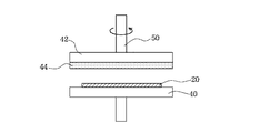
図5は、バフ研磨による平坦化方法を実施するための研磨装置の構成を示す図である。図5に示したように、研磨装置50は、光量調節部材20を吸着保持するための下方保持部40と、この下方保持部40に対向して設けられた上方保持部42とを備えている。図5に示した例では、上方保持部42の下面には、多孔質状の研磨母材に微粒子状の研磨材を浸み込ませた研磨部材44が取り付けられている。そして、上方保持部42の下面に設置した研磨部材44が、下方保持部40に吸着保持されている光量調節部材20の表面に接触するようにした状態で、上方保持部42を回転させる。これによって、光量調節部材20の表面は、研磨材によって表面が研磨されて、凹凸のない平坦面となる。研磨部材44に使用する研磨母材には、例えば、不織布やスウェード等の多孔質体を用いることが好ましい。図5に示した装置では、不織布を用いている。また、研磨材としては、無機酸化物微粒子等を用いることができるが、本態様では、アルミナを主成分とした無機酸化物微粒子を好ましく用いることができる。また、用いる研磨部材の粒径としては、例えば、0.001〜0.3μm程度とすることが好ましい。
【0063】
上記のようにして形成される光量調節領域は、その表面粗さ(Ra)が、該光量を調節する光の波長の1/5以下、更には1/10以下となるように構成することが好ましい。具体的には、例えば、表面粗さ(Ra)が50nm以下となるように構成することが好ましい。かかる範囲の表面粗さは、上記した何れかの平坦化処理方法を用いることによって容易に得られる。
【0064】
本態様では、上記のようにして得られた光量調節部材の両面に、前記第1の態様において説明したと同様の反射防止膜を図1(b)に示したように形成してもよい。上記本態様にかかる製造方法によって得られた光量調節部材は、前記第1の態様において記載した光量調節部材を用いた光量調節装置と同様に、光量調節装置および撮影装置に用いることができる。
【0065】
【実施例】
次に、実施例を挙げて本発明を更に詳細に説明する。以下、「部」及び「%」とあるのは特に断りのない限り質量基準である。
【0066】
先ず、光量調節部材の良否を判断する場合、(1)単体で用いた場合に、色材が光束を散乱或いは屈折することによって生じる光学性能の低下、(2)絞り装置等に組み込んで使用した場合の回折防止効果、(3)分光透過率、の3項目の評価が必要である。ここで(3)の評価項目は、使用する色材の種類によってフィルタの特性を自在に調節でき、且つ市販の分光透過率計を用いて簡単に測定できるので、説明は省略する。一方(2)の評価項目は、絞り羽根の形状や評価時の絞り値(Fナンバー)等の因子が評価結果に大きく影響するため、光量調節部材単独の光学特性を評価するのには適していない。光量調節部材単独の光学特性を評価するためには(1)の評価項目の検討が適している。そこで、後述する各実施例では、それぞれの実施例の製造方法で作成した均一濃度の光量調節部材単独の光学特性についての評価結果を記した。
【0067】
<第1の態様>
(実施例1)
先ず、塗工液として、ポリビニルアルコール(日本合成化学(株)製ゴーセノールGM−14L)を固形分換算で10部からなる水溶液を調製した。次に、得られた塗工液をワイヤーバーを用いて、透明基材としての5mm径のポリエチレンテレフタレートフィルム上に塗工し、熱風乾燥オーブンにより100℃、5分の条件で乾燥を行って、透明基材上に、着色液を吸収・受容し得る層(以下、受容層と呼ぶ)を形成した。このようにして作成した受容層の厚みは、7μmであった。
【0068】
次いで、エネルギー発生素子として電気熱変換体を用いたバブルジェット(登録商標)タイプのインクジェットプリンタ:キヤノン(株)製BJS600のインクタンクに、以下の組成からなる着色液を充填し、上記で作成した透明基材上の受容層上に付与した。その際、光学濃度0.5(透過率32%)が均一濃度になるように付与した。
【0069】

次いで、上記のようにして、着色液を、透明基板上に形成した受容層に付与及び受容させることで形成した光量調節領域上に、以下のようにして透明の平坦化層を設けた。先ず、平坦化層を形成するための塗工液を、下記のようにして調製した。スチレン−ブタジエン共重合体(JSR(株)製TR2000C)を用いて、固形分換算で10部からなるトルエン/メチルエチルケトン溶液からなる塗工液を調製した。次に、この塗工液をワイヤーバーを用いて着色層上に塗工した。更に、熱風乾燥オーブンにより、100℃、5分の条件で、該塗工液の乾燥を行うことによって平坦化層を形成した。このようにして作成した平坦化層の厚みを測定したところ、5μmであった。また、表面粗さ(Ra)は20nmであった。
【0071】
上記のようにして、本実施例の方法で作製された光量調節部材を、キヤノン(株)製デジタルカメラPower Shot G1の撮影レンズの前方に配置し、ISO規格電子スチルカメラ用解像力チャートを撮影した。露出制御モードは絞り開放による絞り優先AEを使用し、光量調節部材の有無に係わらず適正露出が得られるようにした。この撮影画像から白黒バーチャート(像面上での空間周波数:14.5 line pairs/mm)を切り出し、画像の白部のレベルと黒部のレベルの差分を求め、これを評価コントラストとした。次いで、光量調節部材を外して同様の撮影を行ない、画像の白部のレベルと黒部のレベルの差分を求め、これを参照コントラストとした。
【0072】
そして、上記のようにして得られた参照コントラストに対する評価コントラストの比率を求め、これをフィルタコントラストと定義した。本実施例で得られた光量調節部材の場合は、この値は0.93であった。フィルタコントラストの許容下限値は、撮影装置の用途や価格帯によって異なるが、一般的に、普及クラスの撮影装置では0.9以上、高級クラスでは0.92以上が好ましいことがわかっている。このことから、本実施例にかかる製造方法で得られた光量調節部材のフィルタコントラスト値0.93は、充分に高性能であることがわかる。また、得られた受容層上の着色液1ドット径は20μmであり、1ドット面積は、光量調節領域の面積の100分の1であった。
【0073】
(実施例2)
先ず、塗工液として、ポリビニルピロリドン(東京化成工業(株)製K−30)を用いて、固形分換算で10部からなる水溶液を調製した。次に、得られた塗工液をワイヤーバーを用いて、透明基材としてのポリエチレンテレフタレートフィルム上に塗工し、その後、熱風乾燥オーブンにより120℃、10分の条件で乾燥を行って、受容層を形成した。このようにして作成した受容層の厚みは10μmであった。
【0074】
次いで、エネルギー発生素子として電気熱変換体を用いたバブルジェット(登録商標)タイプのインクジェットプリンタ:キヤノン(株)製BJS600のインクタンクに、以下の組成からなる着色液を充填した。そして、このインクジェットプリンタを用いて、上記で作成した受容層上に、光学濃度0.5(透過率32%)の均一濃度になるように着色液を付与した。
【0075】
次いで、上記のようにして着色液が付与されて得られた着色層上に、透明の平坦化層を以下のようにして設けた。先ず、塗工液として、スチレン−ブタジエン共重合体(JSR(株)製TR2000C)を用いて、固形分換算で10部からなるトルエン/メチルエチルケトン溶液を調製する。次に、ワイヤーバーを用いて、この塗工液を上記で形成した着色層上に塗工し、更に、熱風乾燥オーブンにより100℃、5分の条件で乾燥を行って平坦化層を形成した。このようにして形成した平坦化層の厚みを測定したところ、5μmであった。また、表面粗さ(Ra)は25nmであった。
【0077】
上記した本実施例にかかる方法で作製された光量調節部材について、実施例1で行なったと同様の方法でコントラスト値を求めた。この結果、コントラスト値は0.92であり、高性能なものであることがわかった。
【0078】
(実施例3)
実施例1と同様の方法で光量調節部材を作成した。但し、着色液を付与する場合に、透明基材の全面にわたって着色液を均一に付与するのではなく、段階的な濃度勾配を与えて、着色部が、図4に示したようなグラデーションパターンとなるようにした。上記した本実施例にかかる方法で作製した光量調節部材について、実施例1で行なったと同様の方法でコントラスト値を求めて評価を行った。この結果、コントラストの値は0.93であり、高性能なものであった。
【0079】
(実施例4)
実施例1と同様の方法で光量調節部材を作成した。但し、着色液を付与する場合に、透明基材の全面にわたって着色液を均一に付与するのではなく、連続的に濃度勾配をつけ、濃淡の段階が不明瞭な状態のグラデーションパターンとなるようにした。上記した本実施例にかかる方法で作製した光量調節部材について、実施例1で行なったと同様の方法でコントラスト値を求めて評価を行った。この結果、得られたコントラストの値は0.93であり、高性能なものであった。
【0080】
(実施例5)
本実施例では、実施例1と同様の方法で得られた光量調節部材の両面に、更に特開平06−273601号公報の実施例に記載されたものと同様の方法で、無機材料の蒸着多層膜からなる反射防止膜を形成した(図1(b)参照)。この反射防止膜は、それぞれの表面に蒸着したアンダーコート層と、これに積層した繰返し多層膜である多層膜からなるが、具体的には、上記アンダーコート層は、表面に対して良好な密着性を有し、且つ、耐薬品性、及び耐摩耗性に優れたケイ素酸化物SiOx(2>x>1)を主成分とする屈折率n=1.5程度の低屈折率材料からなる膜厚が300nm程度の薄膜であり、この上に積層させた多層膜は、酸化チタンTiO2と酸化ジルコニウムZrO2の混合物を主成分とする高屈折率材料からなる第1層の薄膜と、ケイ素酸化物SiOx(2≧x≧1)を主成分とする低屈折率材料からなる第2層の薄膜と、酸化チタンTiO2と酸化ジルコニウムZrO2の混合物を主成分とする高屈折率材料からなる第3層の薄膜と、ケイ素酸化物SiOx(2≧x≧1)を主成分とする低屈折率材料からなる第4層の薄膜によりなる。上記した本実施例にかかる方法で作製された光量調節部材について、実施例1で行なったと同様の方法でコントラスト値を求めて評価を行った。この結果、得られたコントラストの値は0.93であり、高性能なものであった。
【0081】
<第2の態様>
(実施例6)
本実施例では、透明基材に、厚さ100μmの、透明ポリエチレンテレフタレートフィルムを用いた。このフィルムの上に、エネルギー発生素子として電気熱変換体を用いたバブルジェット(登録商標)タイプのインクジェットプリンタであるキヤノン(株)製BJS600のインクタンクに、透明樹脂材料を有する以下の組成の着色液を充填し、これらを用いて上記の透明基材上に着色部を形成した。この際、上記プリンタによって着色液を付与する場合には、形成される着色部が、光学濃度が0.5(透過率32%)の均一濃度領域となるようにした。また、着色液を付与した後、120℃、20分間熱風乾燥オーブンで加熱乾燥することで、着色液中に含まれる透明樹脂材料であるスチレン−マレイン酸樹脂により着色液を被膜化して、着色部を形成した。ここで形成される着色部は、被膜化したスチレン−マレイン酸樹脂によって、カーボンブラックが結着されてなる着色樹脂層からなる。
【0082】
・黒色顔料(水分散性カーボンブラック)(キャボット
社製IJX−102B) 4%
・スチレン−マレイン酸樹脂のモノエタノールアミン
塩(平均分子量2万、酸価300) 3%
・エチレングリコール 10%
・ジエチレングリコール 15%
・イソプロピルアルコール 2%
・イオン交換水 66%
【0083】
本実施例では、上記のようにして形成した着色部である着色樹脂層の表面に、更に、以下の手順で平坦化層を設けた。先ず、スチレン−ブタジエン共重合体(JSR(株)製TR2000C)を含む塗工液を、固形分換算で上記共重合体が10部となるようにトルエン/メチルエチルケトン溶液を用いて調製した。この塗工液を、ワイヤーバーを用いて着色部上に塗工し、熱風乾燥オーブンにより100℃、10分の条件で乾燥を行った。このようにして作成された平坦化層の厚みは5μmであった。また、表面粗さ(Ra)は25nmであった。
【0084】
上記した本実施例にかかる方法で作製された光量調節部材について、実施例1で行なったと同様の方法でコントラスト値を求めた。この結果、フィルタコントラスト値は0.92であり、充分に高性能であることがわかった。
【0085】
(実施例7)
実施例6で用いたと同様のインクジェットプリンタに、下記の組成からなる着色液を充填した以外は、実施例6とほぼ同様にして、厚さ100μmの透明ポリエチレンテレフタレートフィルム上に着色部を形成した。形成した着色部は、実施例6の場合と同様に、光学濃度が0.5(透過率32%)の均一濃度領域からなるものである。
【0086】
・黒色染料(フードブラック2) 5%
・ヒドロキシプロピルセルロースHPC−H(日本曹
達製) 1%
・エチレングリコール 10%
・ジエチレングリコール 15%
・イソプロピルアルコール 2%
・アセチレノールEH(川研ファインケミカル製)1%
・イオン交換水 66%
【0087】
次に、上記で形成した着色部である着色樹脂層上に、下記の方法で平坦化層を設けた。先ず、塗工液として、スチレン−ブタジエン共重合体(JSR(株)製TR2000C)を固形分換算で10%含むトルエン/メチルエチルケトン溶液を調製し、この塗工液をワイヤーバーを用いて着色部上に塗工した。その後、熱風乾燥オーブンにより100℃、10分の条件で乾燥を行った。このようにして作成された平坦化層の厚みは5μmであった。また、表面粗さ(Ra)は25nmであった。以上の本実施例にかかる方法で作製した光量調節部材を用い、実施例1で行なったと同様の方法でコントラスト値を求めたところ0.93であり、高性能なものであった。
【0088】
(実施例8)
実施例6と同様の方法で光量調節部材を作製した。但し、インクジェットプリンタによって行うインクの付与を、着色部の光学濃度が、実施例6の場合のように均一ではなく、図4に示したように、段階的に変化する濃度勾配を有するものにした。本実施例にかかる方法で作製した光量調節部材を、実施例1で行なったと同様の方法で評価したところ、得られたコントラストの値は0.93と、高性能なものであった。
【0089】
(実施例9)
実施例6と同様の方法で光量調節部材を作製した。但し、インクジェットプリンタによって行うインクの付与を、実施例6の場合のように均一ではなく、着色部の光学濃度が連続的に変化する濃度勾配を与えるものとした。本実施例にかかる方法で作製した光量調節部材を、実施例1で行なったと同様の方法で評価したところ、得られたコントラストの値は0.92と、高性能なものであった。
【0090】
(実施例10)
実施例6と同様にして透明基材上に着色部を形成した。本実施例では、形成した着色部である着色樹脂層の表面を、図5に示した表面研磨装置を用いて研磨して、表面粗さRaが0.2μm以下になるようにした。この際、研磨部材44には、研磨母材である不織布に、研磨材としてアルミナを主成分とした無機酸化物微粒子を浸み込ませたものを用いた。また、研磨材には、0.1μmの粒径のものを使用した。
【0091】
上記のようにして作製した本実施例にかかる光量調節部材を、実施例1と同様の方法にて評価した。その結果、フィルタコントラスト値は0.92であり、高性能なものであった。
【0092】
(実施例11)
実施例10と同様の方法で光量調節部材を作製した。但し、インクジェットプリンタによって行うインクの付与を、着色部の光学濃度が、実施例6の場合のように均一ではなく、図4に示したように、段階的に変化して濃度勾配を有するものとなるようにした。本実施例にかかる方法で作製した光量調節部材を実施例1と同様にして評価したところ、得られたコントラストの値は0.92と、高性能なものであった。
【0093】
(実施例12)
実施例10と同様の方法で光量調節部材を作製した。但し、インクジェットプリンタによって行うインクの付与を、実施例6の場合のように均一ではなく、着色部の光学濃度が連続的に変化する濃度勾配を与えるものとした。本実施例にかかる方法で作製した光量調節部材について、実施例1と同様にして評価したところ、得られたコントラストの値は0.92と、高性能なものであった。
【0094】
(実施例13)
実施例6と同様の方法で得られた光量調節部材の両面に、更に、特開平06−273601号公報の実施例に記載されたものと同様の方法で、無機材料の蒸着多層膜からなる反射防止膜を形成した(図1(b)参照)。この反射防止膜は、それぞれの表面に蒸着したアンダーコート層と、これに積層した繰返し多層膜である多層膜からなるが、具体的には、上記アンダーコート層は、表面に対して良好な密着性を有し、且つ、耐薬品性、及び耐摩耗性に優れたケイ素酸化物SiOX(2>x>1)を主成分とする屈折率n=1.5程度の低屈折率材料からなる膜厚が300nm程度の薄膜であり、この上に積層させた多層膜は、酸化チタンTiO2と酸化ジルコニウムZrO2の混合物を主成分とする高屈折率材料からなる第1層の薄膜と、ケイ素酸化物SiOx(2≧x≧1)を主成分とする低屈折率材料からなる第2層の薄膜と、酸化チタンTiO2と酸化ジルコニウムZrO2の混合物を主成分とする高屈折率材料からなる第3層の薄膜と、ケイ素酸化物SiOx(2≧x≧1)を主成分とする低屈折率材料からなる第4層の薄膜によりなる。このようにして、本実施例にかかる方法で作製した光量調節部材について、実施例1と同様にしてコントラスト値を求めて評価を行ったところ、得られたコントラストの値は0.92と高性能なものであった。
【0095】
【発明の効果】
以上述べたように、本発明によれば、光学特性を十分に満足し得る光量調節部材を、非常に簡便な操作で、歩留まりよく安価に製造することができる光量調節部材の製造方法が提供される。また、本発明によれば、他の製造方式では著しく困難であった、連続的な、或いは段階的な濃度分布を有する光量調節部材を、十分に満足し得る光学特性を達成しつつ簡便に製造することができる光量調節部材の製造方法を提供することができる。また、本発明によれば、光学特性に優れる光量調節部材を具備する多種多様な光量調節装置及び撮影装置を、十分な光学特性を達成しつつ安価に提供することができる。
【図面の簡単な説明】
【図1】本発明による光量調節部材を具備した絞り羽根の図である。
【図2】図1の絞り羽根を用いた光量調節装置の図である。
【図3】図2の光量調節装置を組み込んだ撮影装置の構成図である。
【図4】段階的に濃度勾配を有する光量調節部材の図である。
【図5】光量調節部材の作成に用いた研磨装置の模式的な構成図である。
【符号の説明】
100:光量調節装置
101、102:絞り羽根
101a、102a:溝穴
101b、102b:溝
101c、102c:絞り開口縁
103、903:絞り羽根駆動レバー
103a:孔
103b、103c:突設ピン
101P、102P:光量調節部材
101Q、102Q:光遮断部材
105、905:ガイドピン
106、906:地板の光路孔
111:透明基材
112:着色層
113:反射防止膜
114:平坦化層
400:撮影光学系
401:第1レンズ群
402:第2レンズ群
403:第3レンズ群
404:光学ローパスフィルタ
411:撮像手段
421:表示器
422:操作スイッチ群
423:アクチュエータ
431:CPU
432:絞り駆動回路
433:CCD駆動回路
441:アンプ回路
442:カメラ信号処理回路
443:レコーダ[0001]
TECHNICAL FIELD OF THE INVENTION
The present invention relates to a method for manufacturing a light amount adjusting member, in which a light amount adjusting member that can be effectively used in various fields is easily obtained, such as an optical device such as a digital camera and a video camera, or an electrophotographic recording device. Furthermore, the present invention relates to an excellent light amount adjusting member obtained by the method, a light amount adjusting device using the light amount adjusting member, and a photographing device.
[0002]
[Prior art]
2. Description of the Related Art Generally, an imaging (photographing) optical system used in an optical apparatus such as a camera incorporates a light amount adjusting device for adjusting the light amount of an incident light beam, that is, a so-called aperture device. In such a diaphragm device, a plurality of diaphragm blades form an opening having a predetermined area, and the amount of light passing through the opening is adjusted by adjusting the diameter of the opening with an actuator. However, as the aperture diameter of the aperture is reduced, the influence of diffraction generated at the end of the aperture blade increases, and the imaging performance of the imaging optical system decreases. On the other hand, in order to avoid such a drawback, a filter as a light amount adjusting member is provided in a part of the aperture blade, and instead of reducing the opening diameter, the amount of light flux (light amount) passing through the opening is changed by an optical filter. A technique for attenuating the noise is known. An optical filter used for such a purpose is required to have few optical defects such as light scattering, refraction abnormality, and spectral transmittance deviation.
[0003]
Conventionally, generally used as the light amount adjusting member is a colored film formed by mixing and kneading a coloring material such as a pigment or a dye that absorbs light in a light-transmitting film forming material. Type. However, the light amount adjusting member manufactured by this method is expensive, and cannot sufficiently respond to cost reduction required for expanding demand. Further, in a method in which a coloring material is kneaded into a light-transmitting film material to form a colored film, a light amount adjusting member having a continuous or stepwise density distribution (hereinafter, referred to as “multi-density”) is used. There is also the problem that it is extremely difficult to manufacture.
[0004]
As another known method for manufacturing a light amount adjusting member, there is a method using a silver salt film. According to such a method, a multi-density light amount adjusting member can be manufactured (for example, see Patent Document 1). However, in the case of the light amount adjusting member obtained by this method, the light beam passing through the filter travels straight due to the reflection of the light beam on the surface of the silver particles inside the filter and the diffraction of the light beam passing through the end of the silver particle. The use of a silver halide film causes a specific problem that the image quality is impaired and the imaging performance of the optical system is deteriorated.
[0005]
There is also a proposal for a method of manufacturing a multi-concentration light amount adjusting member by a vapor deposition method (for example, see Patent Document 2). However, in the case of this method, the manufacturing cost is high and the manufacturing cost is high. In addition, since the film thickness changes depending on the concentration, a film thickness difference occurs between a high concentration region and a low concentration region. And the problem that the resolving power is reduced occurs. Furthermore, in this method, it is very difficult to produce a product having a continuous concentration distribution, and even if it is produced, the concentration distribution changes stepwise.
[0006]
In addition, first, an organic dye that fades due to light is kneaded into the film material, and the resulting film is partially irradiated with high-energy light to decompose the organic dye in the irradiated portion, thereby controlling the light intensity of the multi-concentration. There is also a proposal for a method of manufacturing a member (for example, see Patent Document 3). However, in this method, usable coloring materials are limited to those that fade by light, and it is very difficult to obtain a product having sufficient optical characteristics. Furthermore, it can easily be inferred from the complicated manufacturing method that the obtained product will be very expensive.
[0007]
Further, by forming a film of a single concentration into a halftone dot by a printing process such as vapor deposition or photoengraving, and by changing the halftone dot pattern depending on the place, a filter is manufactured as a light amount adjusting member whose transmittance changes steplessly. There is a proposal for a method (for example, see Patent Document 4). However, such a method is to form a film of a predetermined concentration by photolithography or vapor deposition, and irrespective of which process is adopted, the apparatus becomes large, expensive, and the manufacturing cost of the filter increases. There are issues.
[0008]
[Patent Document 1]
JP-A-5-173004
[Patent Document 2]
JP-A-10-133254
[Patent Document 3]
JP-A-10-96971
[Patent Document 4]
JP 2000-352736 A
[0009]
[Problems to be solved by the invention]
Therefore, an object of the present invention is to solve the above-mentioned problems of the prior art, and to economically manufacture a light quantity adjusting member capable of sufficiently satisfying optical characteristics by a simple operation with a low manufacturing cost and a high yield. It is an object of the present invention to provide a method for manufacturing a light amount adjusting member that can be used. Another object of the present invention is to provide a method of manufacturing a light quantity adjusting member that can easily obtain a light quantity adjusting member having a continuous or stepwise density distribution, in addition to the above. Further, an object of the present invention is to manufacture a light amount adjusting member having sufficient optical characteristics easily and inexpensively by the above-described simple manufacturing method, thereby providing a variety of light amount adjusting devices having the light amount adjusting member and photographing. An object of the present invention is to provide an apparatus at low cost while achieving sufficient optical characteristics.
[0010]
[Means for Solving the Problems]
The above object is achieved by the present invention described below. That is, the first aspect of the present invention comprises [1] a step of preparing a transparent substrate having a layer made of a material capable of absorbing a coloring liquid, and coloring the layer containing a coloring material by using a liquid jet recording method. Applying a liquid to form a light quantity adjusting region having a specific optical density.
[0011]
Preferred embodiments of the method for manufacturing the light amount adjusting member according to the first aspect of the present invention include the following [2] to [4]. [2] The method of manufacturing a light quantity adjusting member according to the above [1], wherein the coloring liquid is applied so that the light quantity adjusting area has a density distribution continuously or stepwise. [3] The method for manufacturing a light quantity adjusting member according to the above [1] or [2], further comprising, after the step of forming the light quantity adjusting area, a step of providing a transparent flattening layer on the surface of the light quantity adjusting area. . [4] The above-mentioned [1], wherein the coloring liquid is applied so that one dot area of the coloring liquid formed by applying the coloring liquid on the layer is not more than 1/20 of the area of the light quantity control region. The method for producing a light quantity adjusting member according to any one of [1] to [3].
[0012]
In a second aspect of the present invention, [5] a step of applying a coloring liquid containing at least a transparent resin material and a coloring material on a transparent substrate using a liquid ejection recording method, and curing the transparent resin material Forming a light quantity adjusting region having a specific optical density.
[0013]
Preferred embodiments of the method for manufacturing the light amount adjusting member according to the second aspect of the present invention include the following [6] to [9]. [6] The method for manufacturing a light quantity adjusting member according to the above [5], wherein the coloring liquid is applied so that the light quantity adjusting area has a density distribution continuously or stepwise. [7] The method for manufacturing a light amount adjusting member according to the above [5] or [6], further comprising a step of providing a transparent flattening layer on the surface of the light amount adjusting region after the step of forming the light amount adjusting region. [8] The method for manufacturing a light quantity adjusting member according to the above [5] or [6], further comprising a step of polishing the surface of the light quantity adjusting area after the step of forming the light quantity adjusting area. [9] The color liquid is applied such that one dot area of the color liquid formed by applying the color liquid on the transparent base material is equal to or less than 1/20 of the area of the light quantity control region. ] The manufacturing method of the light quantity adjustment member in any one of [8].
[0014]
As another embodiment of the present invention, the following [10] to [12] can be mentioned. [10] A light amount adjusting member manufactured by the method for manufacturing a light amount adjusting member according to any one of [1] to [9]. [11] In a light amount adjusting device for adjusting a state of a light beam passing through an opening having a predetermined opening diameter, a first region for giving a predetermined transmittance to the light beam, and a device for blocking the light beam Wherein the first region comprises the light amount adjusting member according to the above [10]. [12] The light amount adjusting device according to the above [11], a photographing optical system for forming a subject image, an imaging unit for photoelectrically converting the formed subject image, and a recording unit for recording the photoelectrically converted signal. An imaging device, comprising: the light amount adjusting device is disposed in an imaging optical system.
[0015]
BEST MODE FOR CARRYING OUT THE INVENTION
Hereinafter, the present invention will be described in more detail by way of preferred embodiments of a method for manufacturing a light amount adjusting member according to the present invention.
<First aspect>
The method for manufacturing a light amount adjusting member according to the first aspect of the present invention includes a step of preparing a transparent substrate having a layer made of a material capable of absorbing a coloring liquid, and a step of performing liquid jet recording on the layer of the substrate. Forming a light quantity adjusting region having a specific optical density by applying and receiving a coloring liquid containing a coloring material by a method, and adjusting the amount of transmission of a light beam. Next, following the step of forming a layer made of a material capable of absorbing the coloring liquid on the transparent base material, a step of forming a colored layer to be a light quantity control area is performed. You may comprise so that it may form. Hereinafter, a coating method used for forming a layer made of a material capable of absorbing a coloring liquid on a transparent substrate, and further, a material used in this case will be described.
[0016]
In order to form a layer capable of receiving a colored liquid on a transparent substrate, first, the following materials are added together with other additives as necessary, or water, alcohol, polyhydric alcohols, or other appropriate organic solvents. To dissolve or disperse to prepare a coating solution. Subsequently, the obtained coating liquid is subjected to, for example, a roll coater method, a blade coater method, an air knife coater method, a gate roll coater method, a bar coater method, a size press method, a spray coat method, a gravure coater method, a curtain coater method, and spin coater. It is applied to the substrate surface by a method or the like. Thereafter, drying is performed using, for example, a hot-air drying furnace, a hot drum, a hot plate, or the like to form a receiving layer capable of absorbing and receiving the coloring liquid.
[0017]
The transparent substrate that can be used in the present invention is not particularly limited as long as it has necessary characteristics such as mechanical strength and optical characteristics as a light amount adjusting member. For example, a transparent film substrate composed of polyethylene terephthalate, diacetate, triacetate, cellophane, celluloid, polycarbonate, polyimide, polyvinyl chloride, polyvinylidene chloride, polyacrylate, polyethylene, polypropylene and the like can be mentioned. Further, a glass substrate can be used as long as the above-mentioned required characteristics are satisfied.
[0018]
Further, as a coating liquid material for forming a layer capable of absorbing the coloring liquid provided on the transparent substrate as described above, the coloring liquid is absorbed by a layer formed of the material, and Any material can be used as long as it can receive and fix the color material, and is not particularly limited. For example, a water-soluble resin and a water-dispersible resin as described below can be preferably used.
[0019]
Examples of the water-soluble resin include polyvinyl alcohol, and modified products of polyvinyl alcohol such as anion-modified polyvinyl alcohol, cation-modified polyvinyl alcohol, and acetal-modified polyvinyl alcohol; water-based polyurethane; polyvinyl pyrrolidone, and vinyl pyrrolidone and vinyl acetate copolymer; Modification of polyvinylpyrrolidone such as vinylpyrrolidone and dimethylaminoethyl / methacrylic acid copolymer, quaternized vinylpyrrolidone and dimethylaminoethyl / methacrylic acid copolymer, vinylpyrrolidone and methacrylamidopropyltrimethylammonium chloride copolymer Products: Cellulosic water-soluble resins such as carboxymethylcellulose, hydroxyethylcellulose and hydroxypropylcellulose, and cationized hydroxyethylcell Modified products of cellulose such as cellulose; polyester, polyacrylic acid (ester), melamine resin, or modified products thereof, synthetic resins such as graft copolymers containing at least polyester and polyurethane, albumin, gelatin, casein , Starch, cationized starch, gum arabic, and natural resins such as sodium alginate.
[0020]
Examples of the water-dispersible resin include polyvinyl acetate, ethylene-vinyl acetate copolymer, polystyrene, styrene- (meth) acrylate copolymer, (meth) acrylate-based polymer, and vinyl acetate- (Meth) acrylic acid (ester) copolymer, poly (meth) acrylamide, (meth) acrylamide copolymer, styrene-isoprene copolymer, styrene-butadiene copolymer, styrene-propylene copolymer, polyvinyl ether , Silicone-acrylic copolymers, etc., but of course, the present invention is not limited to these.
[0021]
In addition, the above-mentioned water-soluble resin or water-dispersible resin is used as a binder, and a gap absorbing type in which a pigment such as alumina hydrate, silica or calcium carbonate is mixed with these materials also has an optical characteristic. Can be used within the range that meets.
[0022]
Further, in addition to the above materials, the coating liquid may contain various surfactants, cross-linking agents, and dyes, if necessary, for coating properties, controlling the absorption performance of the coloring liquid, improving mechanical properties, and the like. A fixing agent (waterproofing agent), an antifoaming agent, an antioxidant, a viscosity adjusting agent, a pH adjusting agent, a fungicide, a plasticizer and the like may be contained.
[0023]
In the present invention, a coloring liquid containing a coloring material is applied by a liquid jet recording method to a layer capable of absorbing the coloring liquid on the transparent substrate as described above, and the coloring liquid is absorbed and received in the layer. The light amount adjusting member having a specific density is formed to form the light amount adjusting member. The coloring liquid used at this time is not particularly limited as long as it can be ejected by the fine droplet ejecting apparatus. For example, a coloring liquid obtained by dissolving or dispersing a coloring material in an aqueous or oil-based liquid medium can be used.
[0024]
In the present invention, any of a water-based coloring liquid and an oil-based coloring liquid can be used, but from the viewpoint of ejection reliability, it is preferable to use a water-based coloring liquid. As the coloring material in the coloring liquid, various dyes and pigments can be used, and various metals, inorganic and organic fine particles and the like can also be used. In the present invention, the coloring material constituting the colored liquid refers to a material that controls the transmittance of light in a predetermined wavelength band including visible light, ultraviolet light, and infrared light. That is, when an ND filter (Neutral Density Filter) is manufactured by the method for manufacturing a light amount adjusting member of the present invention, for example, a color material that gives uniform transmission characteristics over the entire visible light band is used. However, the present invention is not limited to this. For example, when forming a light amount adjusting member used for a light amount adjusting device for an infrared camera, it is necessary to use a material that transmits only a specific wavelength in the infrared region, and this is also included in the coloring material. Further, any of the materials that absorb light when controlling the amount of transmitted light, such as those that occur inside the material and those that occur on the surface of the material, are included in the coloring material used in the present invention.
[0025]
As a liquid medium which is a material for forming the aqueous coloring liquid used in the present invention, the following various water-soluble organic solvents can be used. Specifically, for example, carbon number of 1 to 5 such as methyl alcohol, ethyl alcohol, n-propyl alcohol, isopropyl alcohol, n-butyl alcohol, sec-butyl alcohol, tert-butyl alcohol, isobutyl alcohol, n-pentanol, etc. Amides such as dimethylformamide and dimethylacetamide; ketones or keto alcohols such as acetone and diacetone alcohol; ethers such as tetrahydrofuran and dioxane; diethylene glycol, triethylene glycol, tetraethylene glycol, dipropylene glycol; Oxyethylene or oxypropylene copolymers such as tripropylene glycol, polyethylene glycol and polypropylene glycol; Alkylene glycols having an alkylene group containing 2 to 6 carbon atoms, such as pyrene glycol, trimethylene glycol, triethylene glycol, 1,2,6-hexanetriol; glycerin; ethylene glycol monomethyl (or ethyl) ether, diethylene glycol monomethyl Lower alkyl ethers such as (or ethyl) ether and triethylene glycol monomethyl (or ethyl) ether; lower dialkyl ethers of polyhydric alcohols such as triethylene glycol dimethyl (or ethyl) ether and tetraethylene glycol dimethyl (or ethyl) ether Alkanolamines such as monoethanolamine, diethanolamine and triethanolamine; sulfolane, N-methyl-2-pyrrolidone, 2-pyrrolidone Emissions, 1,3-dimethyl-2-imidazolidinone. The water-soluble organic solvents as described above can be used alone or as a mixture.
[0026]
The coloring liquid used in the present invention further contains various surfactants, antifoaming agents, preservatives, etc., in addition to the above-described components, if necessary, to obtain a coloring liquid having desired physical properties. May be done.
[0027]
In the present invention, on a transparent substrate having a layer capable of absorbing and receiving the coloring liquid formed by the method described above coated on the surface, a coloring liquid composed of the above-described material is applied to the fine droplets. A light amount adjusting member having a light amount adjusting region having a specific optical density is applied by using a jetting device. The method of applying the coloring liquid by the micro-droplet ejection device used at this time is not particularly limited. For example, a bubble jet (registered trademark) type using an electrothermal converter as an energy generating element, or a piezo using a piezoelectric element A jet type or the like can be used. A commercially available general-purpose printer can be used as the fine droplet discharge device as the printing device, but the present invention is not limited to this, and a printing device specially manufactured for the present invention may be used.
[0028]
The pattern for applying the coloring liquid is not particularly limited, and may be, for example, a uniform concentration on the entire surface or a gradation pattern having a stepwise concentration gradient as shown in FIG. 4 depending on the purpose. . Further, the gradation pattern may be a gradation pattern in which the gradation of gradation with a continuous concentration gradient is unclear. In particular, according to the manufacturing method of the present invention, it is possible to easily create a light amount adjusting member having a continuous or stepwise density gradient. Further, since the method of forming the concentration gradient pattern has a high degree of freedom, there is an advantage that optical optimization is easy.
[0029]
Further, in order to suitably maintain the optical characteristics of the obtained light amount adjusting member, which can be affected by the optical thickness and the surface roughness, the droplet volume of the coloring liquid applied by the droplet ejection recording method and the landing dot diameter are required. A smaller size is preferable because the difference in the thickness of the receiving layer caused by the difference in the amount of the locally applied coloring liquid is smaller. Therefore, in the present invention, the relationship between the area of the light quantity control area and the area of one dot of the color liquid formed by applying the color liquid on the layer is determined by the fact that the area of one dot of the color liquid is It is preferable to apply the coloring liquid so as to make the area less than 1/20 of the area, more preferably to make it less than 1/50. Further, it is desired that the formed light amount adjusting region is equal to or slightly larger than the diameter of the light beam to be adjusted. The diameter of the light beam here is determined by the focal length or the F number of the optical system to which the light amount adjusting device is applied. It is considered to be about 5 mm or less, though it depends on the optical specifications such as.
[0030]
Further, the surface roughness (Ra) of the formed light quantity adjusting region is preferably 1/5 or less, more preferably 1/10 or less of the wavelength of the light for adjusting the light quantity. Specifically, for example, it is preferable to configure so that the surface roughness (Ra) is 50 nm or less.
[0031]
FIG. 1 shows a diaphragm blade provided with a light amount adjusting member obtained by the manufacturing method according to the first embodiment of the present invention. The diaphragm blade is made of a material provided on a transparent substrate and capable of absorbing a coloring liquid. A specific method for forming a light quantity adjustment region by applying a coloring liquid containing a coloring material to a layer by a liquid jet recording method will be described.
[0032]
The aperture blade illustrated in FIG. 1 includes a light
[0033]
In the method of the present embodiment, after applying the coloring liquid as described above, drying using a hot air drying furnace, a hot drum, a hot plate, or the like may be performed as necessary. In particular, a method in which a cross-linking agent is mixed in a material for forming a layer capable of absorbing a coloring liquid, and a film on a transparent base material is cured by heating or light irradiation to complete a light quantity control region is also effective. It is.
[0034]
Further, in this embodiment, a
[0035]
Specifically, for example, an acrylic or epoxy-based thermosetting resin or photo-curable resin is used, and a coating liquid composed of these resin-forming materials is applied to the surface of the light quantity control region by coating. After forming the coating, the substrate, oven, a method of forming a cured coating by performing baking using a hot plate or the like, or, or by irradiating the substrate with an electron beam or ultraviolet rays A method of forming a cured film or the like can be used. The thickness of the flattening layer formed at this time depends on the required performance and the like, but is preferably, for example, about 0.1 to 30 μm.
[0036]
Further,
[0037]
That is, as an anti-reflection film composed of a vapor-deposited multilayer film of the above-described inorganic material, as described below, an undercoat layer vapor-deposited on both surfaces of the light amount adjusting member, and a configuration composed of a repeated multilayer film laminated thereon. It is preferable to use one. Specifically, for example, the undercoat layer has good adhesion to the synthetic resin material constituting the outermost layer of the light quantity control member, and has excellent chemical resistance and abrasion resistance. Excellent silicon oxide SiO X It is preferable to form a thin film having a thickness d = 200 nm to 300 nm made of a material having a low refractive index of n = 1.49 to 1.59 and having (2>x> 1) as a main component. The multilayer film to be laminated on the undercoat layer is made of titanium oxide TiO. 2 Or zirconium oxide ZrO 2 Alternatively, a first layer thin film made of a material having a high refractive index containing a mixture thereof as a main component, and a silicon oxide SiO x (2 ≧ x ≧ 1) as a main component, a second layer thin film made of a low refractive index material, and titanium oxide TiO laminated thereon 2 Or zirconium oxide ZrO 2 Alternatively, a third layer thin film made of a high-refractive index material mainly containing a mixture of these materials, and a silicon oxide SiO x It is preferable to use a thin film of the fourth layer made of a low refractive index material whose main component is (2 ≧ x ≧ 1).
[0038]
The optical superiority when the optical density of the light amount adjusting member is changed stepwise or continuously is described in, for example, JP-A-6-95208 and JP-A-11-15042. On the other hand, according to the study of the present inventors, if a light amount adjusting member whose optical density is easily manufactured by the method of the present embodiment and whose optical density changes stepwise or continuously is applied to a diaphragm device, the above-described known light-emitting device can be obtained. It turned out that the same effect as the technology can be obtained.
[0039]
Hereinafter, a light amount adjusting device using the light amount adjusting member obtained by the manufacturing method according to the first embodiment of the present invention will be described. Note that the present embodiment is not limited to the configuration described below. FIG. 1 shows an aperture blade provided with the light amount adjusting member of this embodiment, and FIG. 2 shows an aperture blade device provided with such a light amount adjusting member. FIG. 1A is a plan view of the diaphragm blade, and FIG. 1B is a cross-sectional view taken along the line AA ′ of FIG. 1A and viewed in the direction of the arrow. Here, as the light amount adjusting device, a diaphragm device used in a video camera or the like will be described as an example. In FIG. 1A,
[0040]
FIG. 2 is a diagram of a light amount adjusting device using the aperture blade of FIG. In FIG. 2,
[0041]
FIG. 2 shows a state when the throttle is fully opened. When the stop is stopped down from the fully opened state, the
[0042]
FIG. 3 is a schematic layout diagram when the light amount adjusting device shown in FIG. 2 is arranged in an optical device. In the present embodiment, a description will be given of an example of a video camera in which an optical device photoelectrically converts a moving image or a still image into an electric signal by an imaging unit and records the electric signal as digital data. An imaging
[0043]
Reference numeral 421 denotes a display such as a liquid crystal display, which displays the subject image acquired by the
[0044]
The
[0045]
At the optimal exposure, the image of the subject formed on the
[0046]
<Second aspect>
The method for manufacturing a light amount adjusting member according to the second aspect of the present invention includes a step of applying a coloring liquid containing at least a transparent resin material and a coloring material on a transparent substrate using a liquid ejection recording method, Curing to form a light quantity adjustment region having a specific optical density. Hereinafter, the materials used in the manufacturing method according to this embodiment will be described.
[0047]
The transparent substrate that can be used in the present embodiment is particularly limited as long as it has necessary characteristics such as mechanical strength and optical characteristics as a light amount adjusting member, as in the case of the first embodiment described above. It is not something that can be done. For example, a transparent film made of polyethylene terephthalate, diacetate, triacetate, cellophane, celluloid, polycarbonate, polyimide, polyvinyl chloride, polyvinylidene chloride, polyacrylate, polyethylene, polypropylene and the like can be mentioned. In addition, a transparent glass can also be used for the substrate as long as it satisfies the above-mentioned necessary characteristics. Further, the transparent base material appropriately selected from the above-listed materials is transparent by subjecting its surface to various treatments such as plasma treatment, UV treatment, UV ozone treatment, corona treatment, and silane coupling treatment. The surface of the substrate may be modified. These treatments may be useful for controlling the spread of the coloring liquid and improving the adhesion when the coloring part is formed by applying the coloring liquid on the transparent substrate.
[0048]
Next, the coloring liquid applied to the transparent substrate will be described. In this embodiment, it is necessary to use a coloring liquid containing at least a transparent resin material and a coloring material. It is desirable that the transparent resin material used at this time has little coloring in the visible region when it is formed into a film. However, after the coloring liquid is applied to the transparent substrate, the transparent resin material constituting the coloring liquid is cured, and further as a binder for the coloring material such as a pigment contained in the coloring liquid by being formed into a film. It is not particularly limited as long as it functions and fixes the color material on the transparent substrate, and does not impair the optical characteristics imparted to the transparent substrate by the color material constituting the coloring liquid. .
[0049]
Examples of the transparent resin material include resin materials such as polyester resin, alkyd resin, polyurethane resin, polystyrene resin, acrylic resin, nylon resin, epoxy resin, vinyl chloride resin, butyral resin, and polyimide resin. In the present embodiment, when the coloring liquid is applied on the transparent substrate as described above, the coloring liquid is preferably discharged from, for example, a fine droplet discharging device such as an inkjet recording device. It is more preferable to use a hydrophilic resin material as described below.
[0050]
Examples of the hydrophilic transparent resin material include, for example, natural polymers such as lignin sulfonate and shellac, polyacrylates, styrene-acrylic acid copolymer salts, styrene-acrylic acid-ethyl acrylate copolymer salts and the like. Styrene-acrylic acid-alkyl acrylate copolymer salt, styrene-maleic acid copolymer salt, styrene-maleic acid-alkyl acrylate copolymer salt, styrene-maleic half-ester copolymer salt, styrene -Methacrylic acid copolymer salt, vinylnaphthalene-acrylic acid copolymer salt vinylnaphthalene-maleic acid copolymer salt, β-naphthalenesulfonic acid formalin condensed salt, anionic polymers such as polyphosphate, polyvinyl alcohol, methylol Melamine polyvinylpyrrolidone, methylcellulose, hydroxymethyl Cellulose, hydroxypropyl cellulose, and cellulose derivatives such as carboxymethyl cellulose. In this embodiment, one of these resins may be selected, or two or more of them may be used in combination. Others include, for example, a large number of natural resins such as albumin, gelatin, casein, starch, cationized starch, gum arabic, and sodium alginate. Of course, this aspect is not limited to these.
[0051]
In this embodiment, as described above, the coloring liquid containing the transparent resin material as described above is preferably applied to the transparent substrate by discharging the liquid using a microdroplet discharging device or the like. As the coloring liquid used in this embodiment, the same coloring liquid as the coloring liquid described in the first embodiment can be used except that the above-mentioned transparent resin material is contained.
[0052]
In addition to the above, the coloring liquid used in the present embodiment usually contains a liquid medium for the purpose of dissolving or dispersing the transparent resin material and the coloring material described above. As the liquid medium, in the case of an aqueous system, water or a mixture of water and various water-soluble organic solvents is used. As the water-soluble organic solvent used at this time, the same organic solvent as described in the first embodiment can be used.
[0053]
Further, in addition to the above-mentioned components, the various additives described in the first embodiment are preferably used in the present embodiment in order to obtain a coloring solution having desired physical properties, if necessary. It can be used appropriately within a range that satisfies the required optical characteristics.
[0054]
In the method for manufacturing the light amount adjusting member according to the second aspect of the present invention, the coloring liquid having the above-described configuration is formed on the transparent base material as listed above by using a device such as a fine droplet discharging device. And a colored liquid is applied to the transparent substrate to form a colored portion which is a region having a specific optical density. In this case, as a microdroplet discharge method applicable to discharge a coloring liquid to be applied on a transparent substrate, a bubble jet (registered trademark) type using an electrothermal converter as an energy generating element, Alternatively, there is a piezo-jet type using a piezoelectric element, and in this embodiment, any of the micro-droplet ejection devices having these functions can be used. Various types of printers that are already commercially available are available as the minute droplet discharge device as a printing device. In the present embodiment, any of them can be used. Of course, the present invention is not limited to this, and a printing device specially manufactured for this embodiment may be used.
[0055]
The colored portion formed on the transparent substrate by the production method of the present embodiment can have various patterns depending on the purpose so as to be a region having a specific optical density. For example, it may be a region having a uniform optical density, or a gradation pattern having a stepwise density gradient as shown in FIG. Furthermore, a gradation pattern (not shown) may be used in which the gradation of the gradation with a continuous density gradient is unclear. The region in which the optical density is changed continuously or stepwise can be obtained by mounting a plurality of inks having different concentrations stepwise as a coloring liquid to be mounted on the printing apparatus as described above, or It can be easily formed by using the above-mentioned ink and appropriately controlling the ejection amount of the ink.
[0056]
Further, in order to suitably maintain the optical characteristics of the obtained light amount adjusting member that can be affected by the optical thickness and surface roughness, the droplet volume of the coloring liquid applied by the droplet ejection recording method and the landing dot diameter are small. The method is more preferable because the difference in the thickness of the coloring layer caused by the difference in the amount of the coloring liquid applied locally can be reduced. Therefore, it is possible to apply the coloring liquid such that the relationship between the light quantity adjusting region and the dot area of the coloring liquid formed by applying the coloring liquid is not more than 1/20 of the area of the light quantity adjusting region. preferable. More preferably, the coloring liquid is applied so as to be 1/50 or less. It is desired that the light amount adjustment area is equal to or slightly larger than the diameter of the light beam to be adjusted, but the diameter of the light beam here depends on the optical specifications such as the focal length and F number of the optical system to which the light amount adjustment device is applied. However, it is considered to be about 5 mm or less.
[0057]
In particular, according to the method of manufacturing the light amount adjusting member according to the present aspect, the light amount adjusting member having the light amount adjusting region having the density gradient in which the optical density changes continuously or stepwise can be easily manufactured. Furthermore, the method of the present embodiment has the advantage that the optical density gradient pattern that can be formed has a high degree of freedom, so that it is easy to optically optimize the characteristics desired for the light amount adjusting member.
[0058]
In the method of manufacturing the light amount adjusting member of this aspect, it is necessary to apply the coloring liquid on the transparent substrate as described above, and then cure the transparent resin material in the coloring liquid, preferably to form a film. In curing such a transparent resin, a hot air drying oven, a hot drum, a hot plate, or the like can be used. In particular, when a cross-linking agent for the transparent resin to be used is mixed in the coloring liquid, after applying the coloring liquid on the transparent substrate, heating or light irradiation is performed according to the type of the cross-linking agent to perform coloring. It is preferable to form a film by performing a cross-linking and curing treatment of the transparent resin material contained in the liquid.
[0059]
By the way, in the method of the present embodiment, as described above, the colored resin film is formed on the transparent base material to be a light amount control region. Providing a flattening layer to make the optical characteristics uniform is effective in further improving the performance of the light amount adjusting member according to the present embodiment.
[0060]
At this time, the material used for forming the flattening layer is not particularly limited as long as the material satisfies required performances such as adhesion to the resin forming the light amount control region, mechanical strength, and optical characteristics. is not. Specifically, for example, an acrylic or epoxy-based thermosetting resin or photocurable resin can be suitably used. As a method for forming the flattening layer, a coating liquid composed of these resin-forming materials is applied to the surface of the light quantity control region to form a coating film, and then the substrate is placed in an oven, a hot plate, or the like. And baking to form a cured film, or a method of irradiating the base material with an electron beam or ultraviolet rays to form a cured film. The thickness of the flattening layer formed at this time depends on the required performance and the like, but is preferably, for example, about 0.1 to 30 μm.
[0061]
Further, in the method of manufacturing the light amount adjusting member of this aspect, a method of polishing and flattening the surface can be suitably used as means for eliminating partial unevenness generated on the surface of the light amount adjusting region. As a polishing method for the purpose of flattening at this time, a method such as tape polishing or buff polishing can be considered. In this embodiment, buff polishing can be particularly preferably used. In addition, buffing is a method in which an abrasive is placed on the surface of a polishing base material, and a portion of the base material to be polished is brought into contact with the polishing base material in a state where the polishing base material is rotated, thereby forming a surface layer. This is a method of polishing with an abrasive.
[0062]
FIG. 5 is a diagram showing a configuration of a polishing apparatus for performing a planarization method by buff polishing. As shown in FIG. 5, the polishing
[0063]
The light amount adjusting region formed as described above may be configured so that its surface roughness (Ra) is 1/5 or less, and further 1/10 or less, of the wavelength of the light for adjusting the light amount. preferable. Specifically, for example, it is preferable to configure so that the surface roughness (Ra) is 50 nm or less. The surface roughness in such a range can be easily obtained by using any of the above-described planarization treatment methods.
[0064]
In this embodiment, an antireflection film similar to that described in the first embodiment may be formed on both surfaces of the light amount adjusting member obtained as described above, as shown in FIG. The light amount adjusting member obtained by the manufacturing method according to the present aspect can be used for a light amount adjusting device and a photographing device, similarly to the light amount adjusting device using the light amount adjusting member described in the first aspect.
[0065]
【Example】
Next, the present invention will be described in more detail with reference to examples. Hereinafter, “parts” and “%” are based on mass unless otherwise specified.
[0066]
First, when judging the quality of the light amount adjusting member, (1) when used alone, the optical performance is degraded due to scattering or refraction of a light beam, and (2) the light is adjusted and used in a diaphragm device or the like. It is necessary to evaluate three items of the diffraction prevention effect in the case and (3) the spectral transmittance. Here, the evaluation item (3) will not be described because the characteristics of the filter can be freely adjusted depending on the type of the coloring material used and can be easily measured using a commercially available spectral transmittance meter. On the other hand, the evaluation item (2) is suitable for evaluating the optical characteristics of the light amount adjusting member alone because factors such as the shape of the aperture blade and the aperture value (F number) at the time of evaluation greatly affect the evaluation result. Absent. In order to evaluate the optical characteristics of the light amount adjusting member alone, the evaluation item (1) is suitable. Therefore, in each of the embodiments described later, the evaluation results of the optical characteristics of the light amount adjusting member having the uniform density and produced by the manufacturing method of each embodiment are described.
[0067]
<First aspect>
(Example 1)
First, as a coating liquid, an aqueous solution composed of 10 parts of polyvinyl alcohol (Gohsenol GM-14L manufactured by Nippon Synthetic Chemical Co., Ltd.) in terms of solid content was prepared. Next, using a wire bar, the obtained coating liquid was applied on a polyethylene terephthalate film having a diameter of 5 mm as a transparent substrate, and dried at 100 ° C. for 5 minutes using a hot air drying oven. On the transparent substrate, a layer capable of absorbing and receiving the coloring liquid (hereinafter, referred to as a receiving layer) was formed. The thickness of the receiving layer thus formed was 7 μm.
[0068]
Next, a bubble jet (registered trademark) type ink jet printer using an electrothermal converter as an energy generating element: A coloring liquid having the following composition was charged into an ink tank of BJS600 manufactured by Canon Inc. Applied on a receiving layer on a transparent substrate. At that time, an optical density of 0.5 (transmissivity of 32%) was provided so as to be a uniform density.
[0069]
Next, a transparent flattening layer was provided on the light quantity control region formed by applying and receiving the coloring liquid to the receiving layer formed on the transparent substrate as described above. First, a coating liquid for forming a flattening layer was prepared as follows. Using a styrene-butadiene copolymer (TR2000C manufactured by JSR Corp.), a coating liquid composed of a toluene / methyl ethyl ketone solution consisting of 10 parts in terms of solid content was prepared. Next, this coating liquid was applied on the colored layer using a wire bar. Further, the coating liquid was dried in a hot air drying oven at 100 ° C. for 5 minutes to form a flattening layer. When the thickness of the flattening layer thus formed was measured, it was 5 μm. The surface roughness (Ra) was 20 nm.
[0071]
As described above, the light amount adjusting member manufactured by the method of the present embodiment was disposed in front of the photographing lens of the digital camera Power Shot G1 manufactured by Canon Inc., and a resolution chart for an ISO standard electronic still camera was photographed. . In the exposure control mode, the aperture priority AE by opening the aperture is used so that an appropriate exposure can be obtained regardless of the presence or absence of the light amount adjusting member. A black-and-white bar chart (spatial frequency on the image plane: 14.5 line pairs / mm) was cut out from the photographed image, and the difference between the level of the white part and the level of the black part of the image was obtained, and this was used as the evaluation contrast. Next, the same photographing was performed with the light amount adjusting member removed, and the difference between the level of the white part and the level of the black part of the image was obtained, and this was used as the reference contrast.
[0072]
Then, the ratio of the evaluation contrast to the reference contrast obtained as described above was determined, and this was defined as the filter contrast. In the case of the light amount adjusting member obtained in this example, this value was 0.93. Although the allowable lower limit value of the filter contrast varies depending on the use and price range of the photographing apparatus, it is generally found that 0.9 or more is preferable for the popular class photographing apparatus and 0.92 or more for the high-class class. From this, it is understood that the filter contrast value 0.93 of the light amount adjusting member obtained by the manufacturing method according to the present embodiment has sufficiently high performance. Further, the diameter of one dot of the coloring liquid on the obtained receiving layer was 20 μm, and the area of one dot was 1/100 of the area of the light quantity control region.
[0073]
(Example 2)
First, an aqueous solution composed of 10 parts in terms of solid content was prepared using polyvinylpyrrolidone (K-30 manufactured by Tokyo Chemical Industry Co., Ltd.) as a coating liquid. Next, the obtained coating liquid was coated on a polyethylene terephthalate film as a transparent substrate using a wire bar, and then dried at 120 ° C. for 10 minutes in a hot air drying oven to receive the coating liquid. A layer was formed. The thickness of the receiving layer thus formed was 10 μm.
[0074]
Next, a coloring liquid having the following composition was filled into an ink tank of a bubble jet (registered trademark) type inkjet printer using an electrothermal converter as an energy generating element: BJS600 manufactured by Canon Inc. Then, using this ink jet printer, a coloring liquid was applied onto the receiving layer prepared above so as to have a uniform optical density of 0.5 (transmittance: 32%).
[0075]
Next, on the colored layer obtained by applying the coloring liquid as described above, a transparent flattening layer was provided as follows. First, using a styrene-butadiene copolymer (TR2000C manufactured by JSR Corporation) as a coating liquid, a toluene / methyl ethyl ketone solution consisting of 10 parts in terms of solid content is prepared. Next, using a wire bar, this coating solution was applied on the colored layer formed above, and further dried at 100 ° C. for 5 minutes using a hot air drying oven to form a flattening layer. . The thickness of the flattening layer thus formed was measured and found to be 5 μm. The surface roughness (Ra) was 25 nm.
[0077]
With respect to the light amount adjusting member manufactured by the method according to the above-described embodiment, the contrast value was obtained by the same method as that performed in the embodiment 1. As a result, the contrast value was 0.92, which proved to be high performance.
[0078]
(Example 3)
A light amount adjusting member was prepared in the same manner as in Example 1. However, when the coloring liquid is applied, instead of applying the coloring liquid uniformly over the entire surface of the transparent substrate, a stepwise concentration gradient is given, and the colored portion has a gradation pattern as shown in FIG. I made it. The light amount adjusting member manufactured by the method according to the present embodiment described above was evaluated by obtaining a contrast value in the same manner as in the first embodiment. As a result, the value of the contrast was 0.93, which was high performance.
[0079]
(Example 4)
A light amount adjusting member was prepared in the same manner as in Example 1. However, when applying the coloring liquid, instead of applying the coloring liquid uniformly over the entire surface of the transparent substrate, a continuous concentration gradient is applied, so that the gradation pattern becomes a gradation pattern in which the gradation is indistinct. did. The light amount adjusting member manufactured by the method according to the present embodiment described above was evaluated by obtaining a contrast value in the same manner as in the first embodiment. As a result, the obtained contrast value was 0.93, which was high performance.
[0080]
(Example 5)
In the present embodiment, on both surfaces of the light amount adjusting member obtained in the same manner as in the first embodiment, a multi-layer of inorganic material is further deposited by the same method as that described in the embodiment of JP-A-06-273601. An anti-reflection film made of a film was formed (see FIG. 1B). This antireflection film is composed of an undercoat layer deposited on each surface and a multilayer film that is a multilayer film that is repeatedly formed on the undercoat layer. Specifically, the undercoat layer has good adhesion to the surface. Oxide having excellent resistance to chemicals and abrasion resistance x (2>x> 1) is a thin film having a thickness of about 300 nm and made of a low refractive index material having a refractive index of about n = 1.5 and having a refractive index of about 1.5. 2 And zirconium oxide ZrO 2 A thin film of a first layer composed of a high refractive index material mainly containing a mixture of x A second layer thin film made of a low-refractive index material whose main component is (2 ≧ x ≧ 1); 2 And zirconium oxide ZrO 2 A thin film of a third layer composed of a high refractive index material mainly containing a mixture of x It is a thin film of a fourth layer made of a low refractive index material whose main component is (2 ≧ x ≧ 1). The light amount adjusting member manufactured by the method according to the present embodiment described above was evaluated by obtaining a contrast value in the same manner as in the first embodiment. As a result, the obtained contrast value was 0.93, which was high performance.
[0081]
<Second aspect>
(Example 6)
In this example, a transparent polyethylene terephthalate film having a thickness of 100 μm was used as the transparent substrate. Coloring of the following composition having a transparent resin material in an ink tank of BJS600 manufactured by Canon Inc., which is a bubble jet (registered trademark) type ink jet printer using an electrothermal converter as an energy generating element, on this film. The liquid was filled, and using these, a colored portion was formed on the transparent substrate. At this time, when the coloring liquid was applied by the printer, the colored portion to be formed was a uniform density region having an optical density of 0.5 (transmittance 32%). Further, after applying the coloring liquid, the colored liquid is coated with a styrene-maleic acid resin, which is a transparent resin material contained in the coloring liquid, by heating and drying in a hot air drying oven at 120 ° C. for 20 minutes. Was formed. The colored portion formed here is composed of a colored resin layer formed by binding carbon black with a styrene-maleic acid resin formed into a film.
[0082]
・ Black pigment (water-dispersible carbon black) (Cabot
IJX-102B) 4%
・ Monoethanolamine of styrene-maleic acid resin
Salt (average molecular weight 20,000, acid value 300) 3%
・ Ethylene glycol 10%
・ Diethylene glycol 15%
・ Isopropyl alcohol 2%
・ Ion exchange water 66%
[0083]
In this example, a flattening layer was further provided on the surface of the colored resin layer, which was the colored portion formed as described above, by the following procedure. First, a coating solution containing a styrene-butadiene copolymer (TR2000C manufactured by JSR Corporation) was prepared using a toluene / methyl ethyl ketone solution such that the copolymer was 10 parts in terms of solid content. This coating liquid was applied on the colored portion using a wire bar, and dried at 100 ° C. for 10 minutes using a hot air drying oven. The thickness of the flattening layer thus formed was 5 μm. The surface roughness (Ra) was 25 nm.
[0084]
With respect to the light amount adjusting member manufactured by the method according to the above-described embodiment, the contrast value was obtained by the same method as that performed in the embodiment 1. As a result, the filter contrast value was 0.92, indicating that the filter had sufficiently high performance.
[0085]
(Example 7)
A colored portion was formed on a transparent polyethylene terephthalate film having a thickness of 100 μm in substantially the same manner as in Example 6, except that the same ink jet printer as used in Example 6 was filled with a coloring liquid having the following composition. The formed colored portion is a uniform density region having an optical density of 0.5 (transmittance 32%), as in the case of the sixth embodiment.
[0086]
・ 5% of black dye (food black 2)
・ Hydroxypropylcellulose HPC-H (Nippon Soda)
1%
・ Ethylene glycol 10%
・ Diethylene glycol 15%
・ Isopropyl alcohol 2%
・ Acetylenol EH (Kawaken Fine Chemical) 1%
・ Ion exchange water 66%
[0087]
Next, a flattening layer was provided on the colored resin layer as the colored portion formed as described above by the following method. First, a toluene / methyl ethyl ketone solution containing a styrene-butadiene copolymer (TR2000C manufactured by JSR Corporation) containing 10% in terms of solid content was prepared as a coating solution, and the coating solution was applied to the colored portion using a wire bar. Coated. Thereafter, drying was performed in a hot air drying oven at 100 ° C. for 10 minutes. The thickness of the flattening layer thus formed was 5 μm. The surface roughness (Ra) was 25 nm. Using the light amount adjusting member manufactured by the method according to the present embodiment as described above, the contrast value was determined by the same method as that performed in Example 1, and it was 0.93, which was high performance.
[0088]
(Example 8)
A light amount adjusting member was manufactured in the same manner as in Example 6. However, the application of the ink by the ink jet printer was performed so that the optical density of the colored portion was not uniform as in the case of Example 6, but had a density gradient that changed stepwise as shown in FIG. . When the light amount adjusting member manufactured by the method according to the present example was evaluated by the same method as that performed in Example 1, the obtained contrast value was 0.93, which was high performance.
[0089]
(Example 9)
A light amount adjusting member was manufactured in the same manner as in Example 6. However, the application of the ink by the ink jet printer was not uniform as in the case of Example 6, but a density gradient in which the optical density of the colored portion continuously changed was given. When the light amount adjusting member manufactured by the method according to the present example was evaluated by the same method as that performed in Example 1, the obtained contrast value was 0.92, which was high performance.
[0090]
(Example 10)
A colored portion was formed on the transparent substrate in the same manner as in Example 6. In this embodiment, the surface of the colored resin layer, which is the formed colored portion, was polished by using the surface polishing apparatus shown in FIG. 5 so that the surface roughness Ra became 0.2 μm or less. At this time, the polishing
[0091]
The light amount adjusting member according to the present example manufactured as described above was evaluated in the same manner as in Example 1. As a result, the filter contrast value was 0.92, which was high performance.
[0092]
(Example 11)
A light amount adjusting member was manufactured in the same manner as in Example 10. However, the application of the ink by the ink jet printer is performed in such a manner that the optical density of the colored portion is not uniform as in the case of the sixth embodiment, but has a density gradient that changes stepwise as shown in FIG. I made it. When the light amount adjusting member manufactured by the method according to the present example was evaluated in the same manner as in Example 1, the obtained contrast value was 0.92, which was high performance.
[0093]
(Example 12)
A light amount adjusting member was manufactured in the same manner as in Example 10. However, the application of the ink by the ink jet printer was not uniform as in the case of Example 6, but a density gradient in which the optical density of the colored portion continuously changed was given. When the light amount adjusting member manufactured by the method according to this example was evaluated in the same manner as in Example 1, the obtained contrast value was 0.92, which was high performance.
[0094]
(Example 13)
On both surfaces of the light amount adjusting member obtained by the same method as in Example 6, a reflection layer composed of a vapor-deposited multilayer film of an inorganic material is further formed by the same method as that described in the example of JP-A-06-273601. An prevention film was formed (see FIG. 1B). This antireflection film is composed of an undercoat layer deposited on each surface and a multilayer film that is a multilayer film that is repeatedly formed on the undercoat layer. Specifically, the undercoat layer has good adhesion to the surface. Oxide having excellent resistance to chemicals and abrasion resistance X (2>x> 1) is a thin film having a thickness of about 300 nm and made of a low refractive index material having a refractive index of about n = 1.5 and having a refractive index of about 1.5. 2 And zirconium oxide ZrO 2 A thin film of a first layer composed of a high refractive index material mainly containing a mixture of x A second layer thin film made of a low-refractive index material whose main component is (2 ≧ x ≧ 1); 2 And zirconium oxide ZrO 2 A thin film of a third layer composed of a high refractive index material mainly containing a mixture of x It is a thin film of a fourth layer made of a low refractive index material whose main component is (2 ≧ x ≧ 1). As described above, the light amount adjusting member manufactured by the method according to the present embodiment was evaluated by calculating the contrast value in the same manner as in the first embodiment. The obtained contrast value was 0.92, which was a high performance. It was something.
[0095]
【The invention's effect】
As described above, according to the present invention, there is provided a method for manufacturing a light amount adjusting member capable of manufacturing a light amount adjusting member capable of sufficiently satisfying optical characteristics with a very simple operation at a high yield and at a low cost. You. Further, according to the present invention, a light amount adjusting member having a continuous or stepwise density distribution, which is extremely difficult in other manufacturing methods, can be easily manufactured while achieving sufficiently satisfactory optical characteristics. It is possible to provide a method for manufacturing a light amount adjusting member capable of performing the following. Further, according to the present invention, it is possible to provide a variety of light amount adjusting devices and photographing devices including a light amount adjusting member having excellent optical characteristics at low cost while achieving sufficient optical characteristics.
[Brief description of the drawings]
FIG. 1 is a view of an aperture blade provided with a light amount adjusting member according to the present invention.
FIG. 2 is a diagram of a light amount adjusting device using the aperture blade of FIG. 1;
FIG. 3 is a configuration diagram of a photographing device incorporating the light amount adjusting device of FIG. 2;
FIG. 4 is a diagram of a light amount adjusting member having a stepwise density gradient.
FIG. 5 is a schematic configuration diagram of a polishing apparatus used for producing a light amount adjusting member.
[Explanation of symbols]
100: Light intensity adjustment device
101, 102: diaphragm blade
101a, 102a: Slot
101b, 102b: groove
101c, 102c: aperture opening edge
103, 903: diaphragm blade drive lever
103a: hole
103b, 103c: projecting pins
101P, 102P: Light amount adjusting member
101Q, 102Q: light blocking member
105, 905: Guide pins
106, 906: Optical path hole in the main plate
111: transparent substrate
112: colored layer
113: Anti-reflection film
114: Flattening layer
400: shooting optical system
401: first lens group
402: second lens group
403: Third lens group
404: Optical low-pass filter
411: imaging means
421: Display
422: Operation switch group
423: Actuator
431: CPU
432: aperture drive circuit
433: CCD drive circuit
441: Amplifier circuit
442: Camera signal processing circuit
443: Recorder
Claims (1)
Priority Applications (1)
| Application Number | Priority Date | Filing Date | Title |
|---|---|---|---|
| JP2003039391A JP4208598B2 (en) | 2002-02-19 | 2003-02-18 | Manufacturing method of light amount adjusting member, light amount adjusting member, light amount adjusting device and photographing device |
Applications Claiming Priority (5)
| Application Number | Priority Date | Filing Date | Title |
|---|---|---|---|
| JP2002041623 | 2002-02-19 | ||
| JP2002041634 | 2002-02-19 | ||
| JP2002365745 | 2002-12-17 | ||
| JP2002365746 | 2002-12-17 | ||
| JP2003039391A JP4208598B2 (en) | 2002-02-19 | 2003-02-18 | Manufacturing method of light amount adjusting member, light amount adjusting member, light amount adjusting device and photographing device |
Publications (3)
| Publication Number | Publication Date |
|---|---|
| JP2004246306A true JP2004246306A (en) | 2004-09-02 |
| JP2004246306A5 JP2004246306A5 (en) | 2006-03-30 |
| JP4208598B2 JP4208598B2 (en) | 2009-01-14 |
Family
ID=33033325
Family Applications (1)
| Application Number | Title | Priority Date | Filing Date |
|---|---|---|---|
| JP2003039391A Expired - Fee Related JP4208598B2 (en) | 2002-02-19 | 2003-02-18 | Manufacturing method of light amount adjusting member, light amount adjusting member, light amount adjusting device and photographing device |
Country Status (1)
| Country | Link |
|---|---|
| JP (1) | JP4208598B2 (en) |
Cited By (1)
| Publication number | Priority date | Publication date | Assignee | Title |
|---|---|---|---|---|
| US7113318B2 (en) | 2003-04-30 | 2006-09-26 | Canon Kabushiki Kaisha | Light amount control apparatus, photographing apparatus, and filter |
-
2003
- 2003-02-18 JP JP2003039391A patent/JP4208598B2/en not_active Expired - Fee Related
Cited By (1)
| Publication number | Priority date | Publication date | Assignee | Title |
|---|---|---|---|---|
| US7113318B2 (en) | 2003-04-30 | 2006-09-26 | Canon Kabushiki Kaisha | Light amount control apparatus, photographing apparatus, and filter |
Also Published As
| Publication number | Publication date |
|---|---|
| JP4208598B2 (en) | 2009-01-14 |
Similar Documents
| Publication | Publication Date | Title |
|---|---|---|
| JP6317954B2 (en) | Lens unit, imaging module, and electronic device | |
| EP1336871B1 (en) | Production process of a graded neutral density filter, diaphragm with graded neutral density filter and photographing apparatus comprising the diaphragm | |
| JP2012137649A (en) | Optical filter | |
| CN107113372A (en) | optical filter and camera device | |
| JP4227459B2 (en) | OPTICAL FILTER, OPTICAL FILTER MANUFACTURING METHOD, LIGHT CONTROL DEVICE, AND OPTICAL DEVICE | |
| JP4438056B2 (en) | Manufacturing method of light quantity adjusting member | |
| JP3893391B2 (en) | Manufacturing method of ND filter | |
| US7901732B2 (en) | Production process of light amount adjustment member, light amount adjustment member, light amount adjustment device and photographing apparatus | |
| JP4227434B2 (en) | Manufacturing method of light quantity adjusting member | |
| JP2006284947A (en) | Photosensitive resin composition for light shielding film, method for fabricating light shielding film, transfer material, and method for manufacturing transfer material | |
| JP4208598B2 (en) | Manufacturing method of light amount adjusting member, light amount adjusting member, light amount adjusting device and photographing device | |
| JP2004101956A (en) | Optical filter, method for manufacturing optical filter, light amount adjusting device, and photographing device | |
| JP4323893B2 (en) | Manufacturing method of light amount adjusting member, light amount adjusting member, light amount adjusting device and photographing device | |
| JP2004198654A (en) | Light intensity adjustment member | |
| JP2016071278A (en) | Optical filter and light quantity adjusting device, and imaging apparatus | |
| JP2005013877A (en) | Film forming method, light quantity adjusting member manufacturing method, light quantity adjusting member, light quantity adjusting device, and photographing apparatus | |
| JP2005055682A (en) | Manufacturing method of light amount adjusting member, light amount adjusting member, light amount adjusting device and photographing device | |
| JP2005052752A (en) | Manufacturing method of light amount adjusting member, light amount adjusting member, light amount adjusting device and photographing device | |
| JP2005055494A (en) | Light amount adjusting member, method for manufacturing light amount adjusting member, light amount adjusting device and photographing device | |
| JP2005055493A (en) | Manufacturing method of light amount adjusting member, light amount adjusting device and photographing device | |
| JP2005055685A (en) | Light amount adjusting member, method for manufacturing light amount adjusting member, light amount adjusting device and photographing device | |
| JP2005055684A (en) | Manufacturing method of light amount adjusting member, light amount adjusting member, light amount adjusting device and photographing device | |
| JP2005017679A (en) | Manufacturing method of light amount adjusting member, light amount adjusting member, light amount adjusting device and photographing device | |
| JP2004354784A (en) | Optical filter, method for manufacturing optical filter, light amount adjusting device, and photographing device | |
| JP2004354857A (en) | Optical filter and its manufacturing method, light amount adjusting member and its manufacturing method, light amount adjusting device, and photographing device |
Legal Events
| Date | Code | Title | Description |
|---|---|---|---|
| A521 | Written amendment |
Free format text: JAPANESE INTERMEDIATE CODE: A523 Effective date: 20060209 |
|
| A621 | Written request for application examination |
Free format text: JAPANESE INTERMEDIATE CODE: A621 Effective date: 20060209 |
|
| A977 | Report on retrieval |
Free format text: JAPANESE INTERMEDIATE CODE: A971007 Effective date: 20080612 |
|
| A131 | Notification of reasons for refusal |
Free format text: JAPANESE INTERMEDIATE CODE: A131 Effective date: 20080617 |
|
| A521 | Written amendment |
Free format text: JAPANESE INTERMEDIATE CODE: A523 Effective date: 20080811 |
|
| TRDD | Decision of grant or rejection written | ||
| A01 | Written decision to grant a patent or to grant a registration (utility model) |
Free format text: JAPANESE INTERMEDIATE CODE: A01 Effective date: 20081014 |
|
| A01 | Written decision to grant a patent or to grant a registration (utility model) |
Free format text: JAPANESE INTERMEDIATE CODE: A01 |
|
| A61 | First payment of annual fees (during grant procedure) |
Free format text: JAPANESE INTERMEDIATE CODE: A61 Effective date: 20081021 |
|
| R150 | Certificate of patent or registration of utility model |
Free format text: JAPANESE INTERMEDIATE CODE: R150 |
|
| FPAY | Renewal fee payment (event date is renewal date of database) |
Free format text: PAYMENT UNTIL: 20111031 Year of fee payment: 3 |
|
| FPAY | Renewal fee payment (event date is renewal date of database) |
Free format text: PAYMENT UNTIL: 20111031 Year of fee payment: 3 |
|
| FPAY | Renewal fee payment (event date is renewal date of database) |
Free format text: PAYMENT UNTIL: 20121031 Year of fee payment: 4 |
|
| FPAY | Renewal fee payment (event date is renewal date of database) |
Free format text: PAYMENT UNTIL: 20131031 Year of fee payment: 5 |
|
| LAPS | Cancellation because of no payment of annual fees |