JP2004244689A - Method for manufacturing porous material, and porous material - Google Patents
Method for manufacturing porous material, and porous material Download PDFInfo
- Publication number
- JP2004244689A JP2004244689A JP2003036868A JP2003036868A JP2004244689A JP 2004244689 A JP2004244689 A JP 2004244689A JP 2003036868 A JP2003036868 A JP 2003036868A JP 2003036868 A JP2003036868 A JP 2003036868A JP 2004244689 A JP2004244689 A JP 2004244689A
- Authority
- JP
- Japan
- Prior art keywords
- porous body
- alloy system
- producing
- body according
- phase
- Prior art date
- Legal status (The legal status is an assumption and is not a legal conclusion. Google has not performed a legal analysis and makes no representation as to the accuracy of the status listed.)
- Granted
Links
Images


Abstract
Description
【0001】
【発明の属する技術分野】
本発明は、多孔体の製造方法及び多孔体に関する。
【0002】
【従来の技術】
フィルター機能や触媒機能を付加すること、及び軽量化を図るなどの観点より、表面あるいは表面から内部に貫通した微細な空孔を有する多孔体が注目を浴びている。従来、このような多孔体はレーザ加工などの微細加工技術や、電気化学的手法(陽極酸化)、あるいは発泡を用いて実施していた。
【0003】
上記レーザ加工などの方法においては、μmオーダの空孔を形成することは困難であるとともに、空孔の孔径に比較して深さが大きい(高アスペクト比)ものを形成することは困難であった。また、前記電気化学的手法においては、自己組織化によって孔径が決定されてしまうため、その大きさはnmオーダに限定されてしまい、μmオーダの孔径の空孔を有する多孔体の作製は困難であった。さらに、前記発泡を用いた方法では、mmオーダの空孔しか形成することができず、微細な空孔を有する多孔体を形成することは困難であるとともに、前記空孔のアスペクト比についても十分に大きくすることはできないでいた。
【0004】
【発明が解決しようとする課題】
本発明は、空孔の大きさを微小領域で自由に制御することができるとともに、前記空孔のアスペクト比を向上させることのできる、多孔体の製造方法、及び微細かつ高アスペクト比の空孔を有する多孔体を提供することを目的とする。
【0005】
【課題を解決するための手段】
上記目的を達成すべく、本発明は、
原料を溶解させた後、凝固させて2以上の相が規則的に晶出した合金系を作製する工程と、
前記合金系において晶出させた、前記2以上の相の内の少なくとも一つを除去し、この除去された相が位置した部分において空孔を形成する工程と、
を具えることを特徴とする、多孔体の製造方法に関する。
【0006】
本発明によれば、目的とする多孔体を2以上の相が規則的に晶出してなる合金系から構成し、この合金系の少なくとも一相を選択的に除去することによって、その除去部分に空孔を形成して得るものである。したがって、前記合金系の除去すべき相の大きさを所定の範囲に規定すれば、その相を除去することによって、nmオーダからμmオーダの広範囲な領域の微細空孔、具体的には0.1nm〜100μmの大きさの空孔を有する多孔体を簡易に製造することができる。
【0007】
また、前記除去すべき相は、前記合金系の内部に延在しているので、前記相を除去して得た空孔は十分大きな深さを有し、高いアスペクト比、具体的には1000以上のアスペクト比を有する空孔を形成することができる。
【0008】
前記合金系は、原料から溶解凝固させて得る際に、前記凝固の過程で磁場を印加することが好ましい。これによって、前記原料の組成成分、並びに溶解法や凝固法などの製造方法及び製造条件などに依存することなく、微細な規則的組織を有する合金系を簡易に得ることができる。
【0009】
また、前記合金系から前記相を除去する際には、前記合金系を所定の溶液中に浸漬し、浸出させることにより実行する、あるいは前記合金系を所定の電解液中に浸漬し、電気化学的に処理することによって実行することが好ましい。このような方法を用いれば、前記相を簡易に除去することができる。なお、電気化学処理によって相除去を行う場合は、前記電解液中に界面活性剤や粘度調整剤を含有させることが好ましい。これによって、前述した選択的な相除去を簡易に行うことができる。
【0010】
さらに、上述した合金系を製造した後、相除去を行う前において、前記合金系に対して塑性加工を施すことが好ましい。これによって、前記合金系中の規則的組織の大きさを低減させることができ、除去すべき相の大きさも十分に低減することができる。したがって、所望する大きさの微細な空孔を有する多孔体を簡易に得ることができるようになる。
【0011】
また、本発明においては、前記空孔を形成した後の前記合金系に対して電気化学処理を施し、前記合金系に含有された元素を晶出させることが好ましい。例えば、前記合金系中にNi、Co、Tiなどの元素を含有させておくことにより、前記空孔の内表面に前記元素を晶出させることができ、触媒作用や耐食性を付加することができる。
【0012】
【発明の実施の形態】
以下、本発明を発明の実施の形態に基づいて詳細に説明する。
図1〜図5は、本発明の製造方法の各工程を説明するための図である。図1は、多孔体を構成する合金系を製造するために用いる凝固装置図である。図1に示す装置10においては、炉11内に発熱体12を有するとともに、炉11の周囲を覆うようにして電磁石13が設けられている。電磁石13内部にはコイル14が内蔵されている。また、発熱体12の下方には冷却装置15が設けられている。さらに、炉11の下方においては引き下げ装置16が設けられ、装置16に備え付けられた可動棒17の先端には原料Yが取り付けられている。
【0013】
原料Yは、炉11内の発熱体12によって溶解されると同時に、電磁石13による印加磁場の下、装置16によって下方に引き下げられる。そして、冷却装置15によって所定の磁場中凝固され、所定の合金系Xが得られる。この合金系Xは、後の工程において前記合金を構成する少なくとも一つの相を選択的に除去するため、2以上の相を含んでいることが必要である。例えば、合金系Xは偏晶系合金、共晶系合金、及び包晶系合金などから構成することができる。
【0014】
なお、上述した凝固過程において磁場印加は必須の要素ではないが、このような磁場印加を行うことにより、原料Yの組成成分、さらには凝固速度などの製造条件に依存することなく、2以上の相が規則的に晶出した合金系Xを得ることができる。このような観点から、前記印加磁場の大きさは0.5T〜10Tに設定する。
【0015】
図2は、合金系Xの断面を概略的に示した図である。上述した工程を経ることにより、合金系Xは、例えば金属相Aの母材中に金属相Bがロッド状に分散したような構成を呈するようになる。
【0016】
また、上述した凝固過程を経ることにより、合金系X中の各相は相当程度に微細化するが、以下に詳述するように、合金系Xを構成する少なくとも一相を選択的に除去して空孔を形成し、多孔体を作製するので、前記除去すべき相の大きさが直接的に前記空孔の大きさに反映される。したがって、合金系Xを構成する相が十分に微細化されていない場合は、合金系Xに対して塑性加工を施し、構成相の大きさをさらに微細化することが好ましい。
【0017】
前記塑性加工の種類は特に限定されるものではないが、押出加工や圧延加工などを例示することができる。
【0018】
図3は、上述のような工程を経て得た合金系Xから、構成相を選択的に除去するための装置を概略的に示す図である。図3に示す除去装置20は、容器25内に所定の溶液27が満たされている。合金系Xは容器27内に浸漬させ、合金系Xから、所定の相のみを選択的に浸出させて除去する。これによって、合金系Xの、前記相が除去された位置には空孔が形成され、目的とする多孔体を得ることができる。
【0019】
溶液27は酸やアルカリなどの溶解性の強い溶液から構成する。具体的な組成及び濃度については、合金系Xの組成成分などに応じて決定する。
【0020】
図4は、合金系Xから所定の構成相を選択的に除去するための他の装置を概略的に示す図である。図4に示す装置30は、容器30内において電解液37が満たされており、電解液37中に浸漬するようにして参照電極38及び対極39が配置されている。参照電極38あるいは対極39と作用極である合金系X間に所定の電圧を印加し、電解液37中に合金系Xを浸漬すると、合金系Xからは所定の相のみが選択的に腐食及び溶出する。これによって、前記相が除去された位置には空孔が形成され、目的とする多孔体を得ることができる。
【0021】
この場合、参照電極38あるいは対極39と合金系X間に印加する電圧の大きさ、すなわち参照電極38あるいは対極39に対する合金系Xの電位を制御することにより、合金系Xの腐食及び溶出の状態を制御することができる。例えば、所定の相の溶解速度が高い電位に印加されるような状態に設定すれば、合金系Xより、目的とする相のみを選択的に除去することができるようになる。
【0022】
また、所定の相以外の相に対しても溶解速度が高い電位に設定すれば、合金系Xより前記除去すべき相に加えてその他の相、例えば合金系Xの母材を構成する相をも部分的に除去することができるようになる。したがって、最終的に得る多孔体の空孔数、すなわち多孔率を任意に設定することができるようになる。
【0023】
前記のような状態は、例えばAl−In合金において、別個に晶出したAl相及びIn相の内、In相のみを除去するような場合に採用することができる。後者のような状態は、同じくAl−In合金において、前記In相に加えて、前記Al相を部分的に除去するような場合に採用することができる。
【0024】
図4に示す装置を用いる電気化学的手法においては、電解液37中に界面活性剤や粘度調整剤を含有させることができる。これによって、目的とする相の選択的除去をより効果的に行うことができる。界面活性剤としては市販のものを用いることができ、粘度調整剤としてはリン酸などを用いることができる。
【0025】
図5は、本発明における好ましい態様を説明するための図である。上述した工程を経た合金系Xは、樹脂材41などによってその周囲を被覆して絶縁するとともに、合金系Xの下面においてリード線42を付着させる。そして、リード線42を介して所定の電流を流すことにより、合金系Xに対して追加の電気化学処理を実施する。これによって、合金系Xの空孔の内表面に、合金系X中に含有させた他の元素を晶出させることができ、最終的に得る多孔体に対して所定の機能を付加することができる。
【0026】
例えば、原料Y中に予め微量の追加元素を含有させておくことにより、上述した追加の電気化学処理によって、合金系Xより前記追加元素を空孔の内表面上に晶出させることができ、目的とする多孔体に触媒作用や耐食性などの機能を付加することができる。追加の元素としては、Ni、Co及びTiなどを例示することができる。なお、樹脂材41は特に設けなくても良い。
【0027】
以上、図1〜図4の工程、あるいは図1〜図5の工程を経ることにより、nmオーダからμmオーダの広範囲な領域、具体的には0.1nm〜100μmの大きさであって、アスペクト比が1000以上の空孔を有する多孔体を製造することができる。
【0028】
上述したように、本発明の多孔体における前記空孔の大きさは、従来のものに比較して極めて広範囲に設定することができるとともに、極めて高いアスペクト比を呈する。
【0029】
なお、前記空孔の大きさは、空孔形状が円形状の場合はその直径を表し、空孔形状が矩形状の場合はその一辺の長さを表す。
【0030】
【実施例】
Al−32.1wt%In合金を、図1に示すような装置を用いて成長速度100mm/時間以下で凝固させ、Al母材中にInロッドが分散した微細な2つの金属相を生成させた。次いで、前記合金に対して圧延処理を施し、In相の大きさを0.1μm〜10μmに設定した。次いで、前記合金を図4に示すような電解装置内に設置した。電解液は10%硝酸水溶液を用い、参照電極を塩化銀から構成するとともに、対極を白金から構成し、前記参照電極および作用極であるAl−In合金間に所定の電圧を印加することにより、前記合金よりIn相の選択的除去を実施した。
【0031】
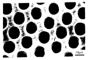
このとき、前記塩化銀の電位に対してAl−In合金の電位を0〜2Vに設定した際には、前記In相のみが選択的に腐食及び溶出されることが確認された。このようにして得た多孔体の顕微鏡写真を図6に示す。図6から明らかなように、このような選択除去工程を経て得た多孔体には約10μmであって、深さの大きな高アスペクト比の空孔が複数形成されていることが分かる。
【0032】
また、前記白金電極の電位を0V〜2Vに設定した際には、前記In相に加えて、前記Al母材が部分的に腐食されて溶出していることが確認された。
【0033】
なお、上述したAl−In合金系においては、In含有量が17重量%から51.5重量%間で変化させた場合においても、上述したような空孔が形成できることが確認された。また、硝酸水溶液における硝酸濃度を5−20%の範囲で変化させた場合においても、上述したような空孔が形成できることが確認された。
【0034】
以上、具体例を挙げながら発明の実施の形態に基づいて本発明を詳細に説明してきたが、本発明は上記内容に限定されるものではなく、本発明の範疇を逸脱しない限りにおいてあらゆる変形や変更が可能である。
【0035】
【発明の効果】
以上説明したように、本発明によれば、空孔の大きさを微小領域で自由に制御することができるとともに、前記空孔のアスペクト比を向上させることのできる、多孔体の製造方法、及び微細かつ高アスペクト比の空孔を有する多孔体を提供することができる。
【図面の簡単な説明】
【図1】本発明の多孔体の製造方法に用いる凝固装置図である。
【図2】本発明の多孔体を構成する合金系の断面図である。
【図3】本発明の多孔体の製造方法に用いる選択除去装置である。
【図4】本発明の多孔体の製造方法に用いる選択除去装置である。
【図5】本発明の多孔体の製造方法における好ましい態様における工程図である。
【図6】本発明の多孔体の表面顕微鏡写真である。
【符号の説明】
10 凝固装置
11 炉
12 発熱体
13 電磁石
14 コイル
15 冷却装置
16 引き下げ装置
17 可動棒
X 合金系
Y 原料
20、30 選択除去装置
25、35 容器
27 溶液
37 電解液
38 参照電極
39 対極
41 樹脂材
42 リード線[0001]
TECHNICAL FIELD OF THE INVENTION
The present invention relates to a method for manufacturing a porous body and a porous body.
[0002]
[Prior art]
BACKGROUND ART From the viewpoint of adding a filter function and a catalyst function and reducing the weight, a porous body having fine pores penetrating from the surface or from the surface to the inside has attracted attention. Conventionally, such a porous body has been implemented by using a fine processing technique such as laser processing, an electrochemical method (anodic oxidation), or foaming.
[0003]
In the above-mentioned methods such as laser processing, it is difficult to form holes of the order of μm, and it is also difficult to form holes having a depth (high aspect ratio) larger than the hole diameter of the holes. Was. Further, in the electrochemical method, since the pore size is determined by self-organization, the size is limited to the order of nm, and it is difficult to produce a porous body having pores having a pore size of the order of μm. there were. Further, in the method using the foaming, only holes of the order of mm can be formed, and it is difficult to form a porous body having fine holes, and the aspect ratio of the holes is also sufficient. Couldn't be larger.
[0004]
[Problems to be solved by the invention]
The present invention provides a method for producing a porous body, and a method for producing a porous material having a fine and high aspect ratio, in which the size of pores can be freely controlled in a minute area and the aspect ratio of the pores can be improved. It is an object to provide a porous body having the following.
[0005]
[Means for Solving the Problems]
In order to achieve the above object, the present invention provides:
Dissolving the raw materials and then solidifying to produce an alloy system in which two or more phases are regularly crystallized;
Removing at least one of the two or more phases crystallized in the alloy system and forming a void in a portion where the removed phase is located;
And a method for producing a porous body.
[0006]
According to the present invention, the target porous body is composed of an alloy system in which two or more phases are regularly crystallized, and by selectively removing at least one phase of the alloy system, It is obtained by forming holes. Therefore, if the size of the phase to be removed in the alloy system is defined within a predetermined range, the phase is removed, and thus fine pores in a wide range from the order of nm to the order of μm, specifically 0.1 μm. A porous body having pores with a size of 1 nm to 100 μm can be easily manufactured.
[0007]
In addition, since the phase to be removed extends inside the alloy system, the pores obtained by removing the phase have a sufficiently large depth and a high aspect ratio, specifically, 1000 Voids having the above aspect ratio can be formed.
[0008]
When the alloy system is obtained by melting and solidifying from a raw material, it is preferable to apply a magnetic field during the solidification process. This makes it possible to easily obtain an alloy system having a fine regular structure without depending on the composition of the raw material, the production method such as the melting method and the solidification method, and the production conditions.
[0009]
Further, when the phase is removed from the alloy system, the phase is removed by immersing the alloy system in a predetermined solution and leaching it, or the alloy system is immersed in a predetermined electrolytic solution to perform electrochemical removal. It is preferable to perform the processing by performing the processing. By using such a method, the phase can be easily removed. When the phase is removed by an electrochemical treatment, it is preferable that a surfactant and a viscosity modifier are contained in the electrolytic solution. Thus, the above-described selective phase removal can be easily performed.
[0010]
Further, after the above-described alloy system is manufactured, it is preferable to subject the alloy system to plastic working before performing phase removal. As a result, the size of the regular structure in the alloy system can be reduced, and the size of the phase to be removed can be sufficiently reduced. Therefore, a porous body having fine pores of a desired size can be easily obtained.
[0011]
Further, in the present invention, it is preferable that the alloy system after the formation of the holes is subjected to an electrochemical treatment to crystallize the elements contained in the alloy system. For example, by including an element such as Ni, Co, or Ti in the alloy system, the element can be crystallized on the inner surface of the pore, and a catalytic action or corrosion resistance can be added. .
[0012]
BEST MODE FOR CARRYING OUT THE INVENTION
Hereinafter, the present invention will be described in detail based on embodiments of the invention.
1 to 5 are views for explaining each step of the manufacturing method of the present invention. FIG. 1 is a diagram of a solidification apparatus used for producing an alloy system constituting a porous body. In an
[0013]
The raw material Y is melted by the
[0014]
The application of a magnetic field is not an essential element in the above-described solidification process, but by applying such a magnetic field, two or more components can be obtained without depending on the composition of the raw material Y and further on the production conditions such as the solidification rate. An alloy system X in which phases are regularly crystallized can be obtained. From such a viewpoint, the magnitude of the applied magnetic field is set to 0.5T to 10T.
[0015]
FIG. 2 is a diagram schematically showing a cross section of alloy system X. Through the above-described steps, the alloy system X comes to have a configuration in which, for example, the metal phase B is dispersed in a rod shape in the base material of the metal phase A.
[0016]
Further, through the above-described solidification process, each phase in the alloy system X is considerably miniaturized. However, as described in detail below, at least one phase constituting the alloy system X is selectively removed. Thus, the size of the phase to be removed is directly reflected on the size of the pore. Therefore, when the phases constituting the alloy system X are not sufficiently refined, it is preferable to subject the alloy system X to plastic working to further refine the size of the constituent phases.
[0017]
The type of the plastic working is not particularly limited, and examples thereof include extrusion and rolling.
[0018]
FIG. 3 is a diagram schematically showing an apparatus for selectively removing a constituent phase from alloy system X obtained through the above-described steps. In the removing
[0019]
The
[0020]
FIG. 4 is a view schematically showing another apparatus for selectively removing a predetermined constituent phase from the alloy system X. In the
[0021]
In this case, by controlling the magnitude of the voltage applied between the
[0022]
Further, if the potential for dissolution is set to a high potential for a phase other than the predetermined phase, other phases, for example, a phase constituting a base material of the alloy X, are added to the phase to be removed from the alloy X. Can also be partially removed. Therefore, the number of pores of the finally obtained porous body, that is, the porosity can be arbitrarily set.
[0023]
Such a state can be adopted, for example, in the case of removing only the In phase from the separately crystallized Al phase and In phase in an Al—In alloy. The latter state can also be employed in the case where the Al phase is partially removed in addition to the In phase in the Al—In alloy.
[0024]
In the electrochemical method using the apparatus shown in FIG. 4, a surfactant or a viscosity modifier can be contained in the
[0025]
FIG. 5 is a diagram for explaining a preferred embodiment of the present invention. The alloy system X that has undergone the above-described steps is covered with a
[0026]
For example, by adding a trace amount of the additional element in the raw material Y in advance, the additional element can be crystallized from the alloy system X on the inner surface of the pores by the additional electrochemical treatment described above, Functions such as catalytic action and corrosion resistance can be added to the target porous body. Examples of the additional element include Ni, Co, and Ti. Note that the
[0027]
As described above, through the steps of FIG. 1 to FIG. 4 or the steps of FIG. 1 to FIG. 5, a wide range of nm order to μm order, specifically 0.1 nm to 100 μm, A porous body having pores with a ratio of 1000 or more can be produced.
[0028]
As described above, the size of the pores in the porous body of the present invention can be set in an extremely wide range as compared with a conventional one, and exhibits an extremely high aspect ratio.
[0029]
The size of the hole indicates the diameter when the hole shape is circular, and indicates the length of one side when the hole shape is rectangular.
[0030]
【Example】
The Al-32.1 wt% In alloy was solidified at a growth rate of 100 mm / hour or less using an apparatus as shown in FIG. 1 to generate two fine metal phases in which In rods were dispersed in the Al base material. . Next, the alloy was subjected to a rolling treatment, and the size of the In phase was set to 0.1 μm to 10 μm. Next, the alloy was placed in an electrolytic device as shown in FIG. The electrolyte is a 10% nitric acid aqueous solution, the reference electrode is made of silver chloride, the counter electrode is made of platinum, and a predetermined voltage is applied between the reference electrode and the Al-In alloy serving as a working electrode. The In phase was selectively removed from the alloy.
[0031]
At this time, when the potential of the Al-In alloy was set to 0 to 2 V with respect to the potential of the silver chloride, it was confirmed that only the In phase was selectively corroded and eluted. FIG. 6 shows a micrograph of the porous body thus obtained. As is clear from FIG. 6, the porous body obtained through such a selective removal step has a plurality of holes with a large depth of about 10 μm and a high aspect ratio.
[0032]
When the potential of the platinum electrode was set to 0 V to 2 V, it was confirmed that the Al base material was partially corroded and eluted in addition to the In phase.
[0033]
In the Al-In alloy system described above, it was confirmed that the above-described pores could be formed even when the In content was changed from 17% by weight to 51.5% by weight. It was also confirmed that the above-described pores could be formed even when the nitric acid concentration in the aqueous nitric acid solution was changed in the range of 5 to 20%.
[0034]
As described above, the present invention has been described in detail based on the embodiments of the present invention with specific examples. However, the present invention is not limited to the above description, and any modifications or changes may be made without departing from the scope of the present invention. Changes are possible.
[0035]
【The invention's effect】
As described above, according to the present invention, it is possible to freely control the size of pores in a minute region, and to improve the aspect ratio of the pores, a method for manufacturing a porous body, and A porous body having fine and high aspect ratio pores can be provided.
[Brief description of the drawings]
FIG. 1 is a diagram of a solidification apparatus used in a method for producing a porous body of the present invention.
FIG. 2 is a sectional view of an alloy system constituting the porous body of the present invention.
FIG. 3 is a selective removal device used in the method for producing a porous body of the present invention.
FIG. 4 is a selective removal device used in the method for producing a porous body of the present invention.
FIG. 5 is a process chart in a preferred embodiment of the method for producing a porous body of the present invention.
FIG. 6 is a surface micrograph of a porous body of the present invention.
[Explanation of symbols]
REFERENCE SIGNS
Claims (18)
前記合金系において晶出させた、前記2以上の相の内の少なくとも一つを除去し、この除去された相が位置した部分において空孔を形成する工程と、
を具えることを特徴とする、多孔体の製造方法。Dissolving the raw materials and then solidifying to produce an alloy system in which two or more phases are regularly crystallized;
Removing at least one of the two or more phases crystallized in the alloy system, and forming pores in a portion where the removed phase is located;
A method for producing a porous body, comprising:
Priority Applications (1)
| Application Number | Priority Date | Filing Date | Title |
|---|---|---|---|
| JP2003036868A JP4247379B2 (en) | 2003-02-14 | 2003-02-14 | Method for producing porous body |
Applications Claiming Priority (1)
| Application Number | Priority Date | Filing Date | Title |
|---|---|---|---|
| JP2003036868A JP4247379B2 (en) | 2003-02-14 | 2003-02-14 | Method for producing porous body |
Publications (2)
| Publication Number | Publication Date |
|---|---|
| JP2004244689A true JP2004244689A (en) | 2004-09-02 |
| JP4247379B2 JP4247379B2 (en) | 2009-04-02 |
Family
ID=33021840
Family Applications (1)
| Application Number | Title | Priority Date | Filing Date |
|---|---|---|---|
| JP2003036868A Expired - Lifetime JP4247379B2 (en) | 2003-02-14 | 2003-02-14 | Method for producing porous body |
Country Status (1)
| Country | Link |
|---|---|
| JP (1) | JP4247379B2 (en) |
Cited By (2)
| Publication number | Priority date | Publication date | Assignee | Title |
|---|---|---|---|---|
| JP2007290012A (en) * | 2006-04-26 | 2007-11-08 | Toshiba Corp | Manufacturing method of anisotropy porous material |
| KR20200030295A (en) * | 2018-09-12 | 2020-03-20 | 연세대학교 산학협력단 | Nanoporous transition metal alloy and manufacturing the same |
Citations (10)
| Publication number | Priority date | Publication date | Assignee | Title |
|---|---|---|---|---|
| JPH0394032A (en) * | 1989-04-14 | 1991-04-18 | Karl Sieradzki | Micro and nanoporous metal structure |
| JPH03230421A (en) * | 1990-02-03 | 1991-10-14 | Sumitomo Electric Ind Ltd | Manufacture of nb3al superconducting wire |
| JPH0536576A (en) * | 1991-07-30 | 1993-02-12 | Nippon Steel Corp | Expansion method of active surface area of alloy material to which intermetallic compound has been dispersed uniformly |
| JPH06100959A (en) * | 1992-09-22 | 1994-04-12 | Nippon Steel Corp | Material having porous layer |
| JP2001009800A (en) * | 1999-04-27 | 2001-01-16 | Canon Inc | Nano structure and manufacture thereof |
| JP2001138300A (en) * | 1999-08-30 | 2001-05-22 | Canon Inc | Manufacturing method for structure having small holes, structure manufactured by the method, and structure device using the structure |
| WO2001065600A2 (en) * | 2000-03-01 | 2001-09-07 | Hewlett-Packard Company | Nanoscale patterning for the formation of extensive wires |
| JP2002285240A (en) * | 2001-03-26 | 2002-10-03 | Univ Osaka | Method for manufacturing material having oriented structure or anisotropic structure |
| JP2002332578A (en) * | 2001-05-10 | 2002-11-22 | Canon Inc | Method of manufacturing nano-structure |
| JP2003025298A (en) * | 2001-05-11 | 2003-01-29 | Canon Inc | Structure having pore and its manufacturing method |
-
2003
- 2003-02-14 JP JP2003036868A patent/JP4247379B2/en not_active Expired - Lifetime
Patent Citations (10)
| Publication number | Priority date | Publication date | Assignee | Title |
|---|---|---|---|---|
| JPH0394032A (en) * | 1989-04-14 | 1991-04-18 | Karl Sieradzki | Micro and nanoporous metal structure |
| JPH03230421A (en) * | 1990-02-03 | 1991-10-14 | Sumitomo Electric Ind Ltd | Manufacture of nb3al superconducting wire |
| JPH0536576A (en) * | 1991-07-30 | 1993-02-12 | Nippon Steel Corp | Expansion method of active surface area of alloy material to which intermetallic compound has been dispersed uniformly |
| JPH06100959A (en) * | 1992-09-22 | 1994-04-12 | Nippon Steel Corp | Material having porous layer |
| JP2001009800A (en) * | 1999-04-27 | 2001-01-16 | Canon Inc | Nano structure and manufacture thereof |
| JP2001138300A (en) * | 1999-08-30 | 2001-05-22 | Canon Inc | Manufacturing method for structure having small holes, structure manufactured by the method, and structure device using the structure |
| WO2001065600A2 (en) * | 2000-03-01 | 2001-09-07 | Hewlett-Packard Company | Nanoscale patterning for the formation of extensive wires |
| JP2002285240A (en) * | 2001-03-26 | 2002-10-03 | Univ Osaka | Method for manufacturing material having oriented structure or anisotropic structure |
| JP2002332578A (en) * | 2001-05-10 | 2002-11-22 | Canon Inc | Method of manufacturing nano-structure |
| JP2003025298A (en) * | 2001-05-11 | 2003-01-29 | Canon Inc | Structure having pore and its manufacturing method |
Non-Patent Citations (1)
| Title |
|---|
| 阿部 秀夫 著, 金属組織学序論, vol. 10版, JPN4006016445, 30 March 1979 (1979-03-30), JP, pages 137 - 153, ISSN: 0000769836 * |
Cited By (3)
| Publication number | Priority date | Publication date | Assignee | Title |
|---|---|---|---|---|
| JP2007290012A (en) * | 2006-04-26 | 2007-11-08 | Toshiba Corp | Manufacturing method of anisotropy porous material |
| KR20200030295A (en) * | 2018-09-12 | 2020-03-20 | 연세대학교 산학협력단 | Nanoporous transition metal alloy and manufacturing the same |
| KR102161347B1 (en) | 2018-09-12 | 2020-09-29 | 연세대학교 산학협력단 | Nanoporous transition metal alloy and manufacturing the same |
Also Published As
| Publication number | Publication date |
|---|---|
| JP4247379B2 (en) | 2009-04-02 |
Similar Documents
| Publication | Publication Date | Title |
|---|---|---|
| Zhang et al. | Electrochemical fabrication of nanoporous copper films in choline chloride–urea deep eutectic solvent | |
| Zhang et al. | On the electrochemical dealloying of Al-based alloys in a NaCl aqueous solution | |
| JP5144270B2 (en) | Co-base alloy functional member and method for manufacturing the same | |
| JP4782662B2 (en) | Porous metallic glass and method for producing the same | |
| CN105624456B (en) | A kind of spongy superfine nano porous metals and preparation method | |
| JPH0394032A (en) | Micro and nanoporous metal structure | |
| CN105648260B (en) | A kind of method that copper-iron alloy removal alloying prepares micron porous metal copper billet body | |
| Hassel et al. | Nanostructures from directionally solidified NiAl–W eutectic alloys | |
| EP1604756A2 (en) | method for producing metallic reticular structures | |
| JP5846591B2 (en) | Implant | |
| JP4247379B2 (en) | Method for producing porous body | |
| Dan et al. | Polyvinylpyrrolidone macromolecules function as a diffusion barrier during dealloying | |
| JP6747670B2 (en) | Method for manufacturing metal member | |
| Suárez et al. | Fabrication of porous and nanoporous aluminum via selective dissolution of Al-Zn alloys | |
| CN109338150A (en) | A kind of porous copper alloy and preparation method thereof | |
| JP3953408B2 (en) | Soft aluminum foil for medium and low pressure electrolytic capacitors for AC etching and method for producing the same | |
| RU2325472C2 (en) | Method of metallic powder production | |
| Chuang | Powder-based Dealloying–Scalable Production of Nanostructured Composites | |
| CN105420532A (en) | Metal-hole antibacterial metallic silver at nanoscale and preparation method of metallic silver | |
| JP2004322143A (en) | Method for manufacturing porous metallic body | |
| KR20110114252A (en) | Method of manufacturing amorphous metal foams by selective solvent extrusion using amorphous powder and amorphous metal foams manufactured the method | |
| DE1533348A1 (en) | Raney metal in the form of self-supporting plates, as well as processes for its manufacture | |
| US20060252640A1 (en) | Metal or metal oxide porous material prepared by use of dextran or related soluble carbohydrate polymer | |
| KR101720437B1 (en) | Synthesis Method for Fabricating Nano-porous Metal Structure Utilizing Electro Reduction Process | |
| Gaskey | Liquid Metal Dealloying in Multicomponent Systems–Towards Next-Generation Metal Composites |
Legal Events
| Date | Code | Title | Description |
|---|---|---|---|
| A131 | Notification of reasons for refusal |
Free format text: JAPANESE INTERMEDIATE CODE: A131 Effective date: 20060221 |
|
| A521 | Request for written amendment filed |
Free format text: JAPANESE INTERMEDIATE CODE: A523 Effective date: 20060424 |
|
| A711 | Notification of change in applicant |
Free format text: JAPANESE INTERMEDIATE CODE: A712 Effective date: 20060519 |
|
| A521 | Request for written amendment filed |
Free format text: JAPANESE INTERMEDIATE CODE: A821 Effective date: 20060519 |
|
| A02 | Decision of refusal |
Free format text: JAPANESE INTERMEDIATE CODE: A02 Effective date: 20060912 |
|
| A521 | Request for written amendment filed |
Free format text: JAPANESE INTERMEDIATE CODE: A523 Effective date: 20061113 |
|
| A911 | Transfer to examiner for re-examination before appeal (zenchi) |
Free format text: JAPANESE INTERMEDIATE CODE: A911 Effective date: 20061211 |
|
| A912 | Re-examination (zenchi) completed and case transferred to appeal board |
Free format text: JAPANESE INTERMEDIATE CODE: A912 Effective date: 20070126 |
|
| A01 | Written decision to grant a patent or to grant a registration (utility model) |
Free format text: JAPANESE INTERMEDIATE CODE: A01 |
|
| R150 | Certificate of patent or registration of utility model |
Ref document number: 4247379 Country of ref document: JP Free format text: JAPANESE INTERMEDIATE CODE: R150 Free format text: JAPANESE INTERMEDIATE CODE: R150 |
|
| EXPY | Cancellation because of completion of term |