【0001】
【発明の属する技術分野】
本発明は、立体像を撮影する装置に関する。
【0002】
【従来の技術】
従来、立体像を撮影、表示するには、水平方向に所定の距離を離して置いた二台のカメラで撮影し、偏光ガラスやカラーフィルタなどを用いた眼鏡や、専用のビュアーを使って二枚の撮影像を左右それぞれの目で見えるようにする方法や、レンチキュラーレンズを使って、それぞれ異なる角度から見えるようにしたものがある。
【0003】
また、特殊なビュアーを使わずに見ることができる立体像を撮影、表示する方法としては、平面状に並んだ凸レンズ群を使って被写体の写真を撮り、同様の凸レンズ群を使って再生するインテグラルフォトグラフィや、ホログラムなどがある。
【0004】
【発明が解決しようとする課題】
眼鏡やビュアーを使って見なければならないものは、不特定の人に立体像を提供するにははなはだ不便である。またレンチキュラーレンズを使って、複数の像を異なる角度から見えるようにしたものは、見る角度によって数枚の写真が切り替わって見えるため、見る位置によっては二重の像が見えたり、観察者が移動しながら見る時に不自然さを感じることがあり、また良好な観察ができる角度範囲が比較的狭いという問題もある。
【0005】
またインテグラルフォトグラフィは、撮影機の製作が容易でない上にそのままでは遠近の逆転した不自然な立体像となってしまう問題があり、ホログラムは更に撮影が難しく、簡単な装置で気軽に立体像を楽しむことは困難である。
【0006】
本発明者は、これらの課題を解決すべく、従来とは異なる立体像の撮影及び表示方法を考案し、すでに特願2002−112824に出願済みであるが、その後さらに検討を続け、該出願特許の表示装置で表示ができる立体像を、より簡単に撮影できる撮影装置を発明するに至った。
【0007】
【課題を解決するための手段】
本発明の請求項1は、反射面を平行にして、反射面に垂直な方向に並んだダブプリズムの列と、該ダブプリズム列を挟むように、該ダブプリズム列から等しい距離を離れた位置に置かれた対物レンズ(凸レンズ)及び第2の凸レンズと、該ダブプリズムの入射面及び反射面に平行な軸を持つシリンドリカルレンズが該ダブプリズム列と平行に並んでなるレンチキュラーレンズと、その撮像面が該レンチキュラーレンズに平行に、該シリンドリカルレンズの焦点距離にほぼ等しい間隔をもって置かれた撮像手段と、該ダブプリズムの反射面に垂直な水平スリットを有する遮光板からなり、被写体の像が該対物レンズ、該ダブプリズム列、第2の凸レンズ、該レンチキュラーレンズを通って該撮像手段に投影される装置であって、該水平スリットは被写体と対物レンズの間、ないし対物レンズとダブプリズム列の間、ないしダブプリズム列と第2の凸レンズの間、ないし第2の凸レンズとレンチキュラーレンズの間のいずれかに置かれて光線を規制することを特徴とする立体像撮影装置である。
【0008】
本発明の請求項2は、対物レンズ(凸レンズ)と第2の凸レンズの焦点距離が等しく、第2の凸レンズと撮像面の距離が、その焦点距離に等しいことを特徴とする請求項1に記載の立体像撮影装置である。
【0009】
本発明の請求項3は、第2の凸レンズの焦点距離が対物レンズ(凸レンズ)の焦点距離より短く、被写体の縮小像を撮影する請求項1に記載の立体像撮影装置であって、さらにレンチキュラーレンズの前に凹レンズが置かれ、対物レンズの焦点距離をf1、第2の凸レンズの焦点距離をf2とするとき、第2の凸レンズと該凹レンズの距離L1はf2より小さく、該凹レンズの焦点距離f3(負の値)は数1で示され、第2の凸レンズと撮像面までの距離L2が数2で表されることを特徴とする立体像撮影装置である。
【0010】
本発明の請求項4は、第2の凸レンズの焦点距離が対物レンズ(凸レンズ)の焦点距離より長く、被写体の拡大像を撮影する請求項1に記載の立体像撮影装置であって、さらにレンチキュラーレンズの前に第3の凸レンズが置かれ、対物レンズの焦点距離をf1、第2の凸レンズの焦点距離をf2とするとき、第2の凸レンズと第3の凸レンズの距離L1はf2より小さく、第3の凸レンズの焦点距離f3は数1で示され、第2の凸レンズと撮像面までの距離L2が数2で表されることを特徴とする立体像撮影装置である。
【0011】
本発明の請求項5は、反射面を平行にして、反射面に垂直な方向に並んだダブプリズムの列と、該ダブプリズム列を挟むように、該ダブプリズム列から等しい距離を離れた位置に置かれた対物レンズ(凸レンズ)及び第2の凸レンズと、該ダブプリズムの入射面及び反射面に平行なスリットが該ダブプリズム列と平行に並んだスリット板と、その撮像面が該スリット板に平行に置かれた撮像手段と、該ダブプリズムの反射面に垂直な水平スリットを有する遮光板からなり、被写体の像が該対物レンズ、該ダブプリズム列、第2の凸レンズ、該スリット板を通って該撮像手段に投影される装置であって、該水平スリットは被写体と対物レンズの間、ないし対物レンズとダブプリズム列の間、ないしダブプリズム列と第2の凸レンズの間、ないし第2の凸レンズとスリット板の間のいずれかに置かれて光線を規制することを特徴とする立体像撮影装置である。
【0012】
本発明の請求項6は、対物レンズ(凸レンズ)と第2の凸レンズの焦点距離が等しく、第2の凸レンズと撮像面の距離が、その焦点距離に等しいことを特徴とする請求項5に記載の立体像撮影装置である。
【0013】
本発明の請求項7は、第2の凸レンズの焦点距離が対物レンズ(凸レンズ)の焦点距離より短く、被写体の縮小像を撮影する請求項5に記載の立体像撮影装置であって、さらにスリット板の前に凹レンズが置かれ、対物レンズの焦点距離をf1、第2の凸レンズの焦点距離をf2とするとき、第2の凸レンズと該凹レンズの距離L1はf2より小さく、該凹レンズの焦点距離f3(負の値)は数1で示され、第2の凸レンズと撮像面までの距離L2が数2で表されることを特徴とする立体像撮影装置である。
【0014】
本発明の請求項8は、第2の凸レンズの焦点距離が対物レンズ(凸レンズ)の焦点距離より長く、被写体の拡大像を撮影する請求項5に記載の立体像撮影装置であって、さらにスリット板の前に第3の凸レンズが置かれ、対物レンズの焦点距離をf1、第2の凸レンズの焦点距離をf2とするとき、第2の凸レンズと第3の凸レンズの距離L1はf2より小さく、第3の凸レンズの焦点距離f3は数1で示され、第2の凸レンズと撮像面までの距離L2が数2で表されることを特徴とする立体像撮影装置である。
【0015】
本発明の請求項9は、屋根状に直交する反射面が、その稜線に垂直な方向に多数並んでなる反射面群と、該反射面群の前に置かれた凸レンズと、さらに該凸レンズの前に傾斜して置かれたハーフミラーと、該反射面群の並ぶ方向と平行な水平スリットを有する遮光板と、該反射面群と同じ方向にシリンドリカルレンズが並んでなるレンチキュラーレンズと、その撮像面が該レンチキュラーレンズに平行に、該シリンドリカルレンズの焦点距離にほぼ等しい間隔をもって置かれた撮像手段とからなり、被写体からの光線がハーフミラーを透過ないし反射後、該凸レンズを通り、該反射面群で反射して再び該凸レンズを通り、該ハーフミラーを反射ないし透過し、該レンチキュラーレンズを通って該撮像手段に投影される装置であって、該水平スリットは被写体とハーフミラーの間ないしハーフミラーとレンチキュラーレンズの間のいずれかに置かれて光線を規制することを特徴とする立体像撮影装置である。
【0016】
本発明の請求項10は、屋根状に直交する反射面が、その稜線に垂直な方向に多数並んでなる反射面群と、該反射面群の前に置かれた凸レンズと、さらに該凸レンズの前に傾斜して置かれたハーフミラーと、該反射面群の並ぶ方向と平行な水平スリットを有する遮光板と、平行なスリットが該反射面群と同じ方向に多数並んだスリット板と、その撮像面が該スリット板に平行に置かれた撮像手段とからなり、被写体からの光線がハーフミラーを透過ないし反射後、該凸レンズを通り、該反射面群で反射して再び該凸レンズを通り、該ハーフミラーを反射ないし透過し、該スリット板を通って該撮像手段に投影される装置であって、該水平スリットは被写体とハーフミラーの間ないしハーフミラーとスリット板の間のいずれかに置かれて光線を規制することを特徴とする立体像撮影装置である。
【0017】
本発明の請求項11は、屋根状に直交する微小な反射面が、その稜線に垂直な方向に線状に多数並んでなる反射面群と、該反射面群の前に置かれた凸レンズと、さらに該凸レンズの前に傾斜して置かれたハーフミラーと、該反射面群と同じ方向にシリンドリカルレンズが並んでなるレンチキュラーレンズと、その撮像面が該レンチキュラーレンズに平行に、該シリンドリカルレンズの焦点距離にほぼ等しい間隔をもって置かれた撮像手段とからなり、被写体からの光線がハーフミラーを透過ないし反射後、該凸レンズを通り、該反射面群で反射して再び該凸レンズを通り、該ハーフミラーを反射ないし透過し、該レンチキュラーレンズを通って該撮像手段に投影されることを特徴とする立体像撮影装置である。
【0018】
本発明の請求項12は、屋根状に直交する微小な反射面が、その稜線に垂直な方向に線状に多数並んでなる反射面群と、該反射面群の前に置かれた凸レンズと、さらに該凸レンズの前に傾斜して置かれたハーフミラーと、平行なスリットが該反射面群と同じ方向に多数並んだスリット板と、その撮像面が該スリット板に平行に置かれた撮像手段とからなり、被写体からの光線がハーフミラーを透過ないし反射後、該凸レンズを通り、該反射面群で反射し、再び該凸レンズを通って該ハーフミラーを反射ないし透過し、該スリット板を通って該撮像手段に投影されることを特徴とする立体像撮影装置である。
【0019】
本発明の請求項13は、屋根状に直交する反射面が、その稜線に垂直な方向に多数並んでなる反射面群と、該反射面群の前に傾斜して置かれたハーフミラーと、該ハーフミラーの一方の面に面して置かれた対物レンズ(凸レンズ)と、ハーフミラーの他方の面に面して置かれた第2の凸レンズと、該反射面群の並ぶ方向と平行な水平スリットを有する遮光板と、該反射面群と同じ方向にシリンドリカルレンズが並んでなるレンチキュラーレンズと、その撮像面が該レンチキュラーレンズに平行に、該シリンドリカルレンズの焦点距離にほぼ等しい間隔をもって置かれた撮像手段とからなり、被写体からの光線が対物レンズを通ってハーフミラーを透過ないし反射後、該反射面群で反射し、再び該ハーフミラーを反射ないし透過し、第2の凸レンズを通り、該レンチキュラーレンズを通って該撮像手段に投影される装置であって、該水平スリットは被写体とハーフミラーの間ないしハーフミラーとレンチキュラーレンズの間のいずれかに置かれて光線を規制することを特徴とする立体像撮影装置である。
【0020】
本発明の請求項14は、屋根状に直交する微小な反射面が、その稜線に垂直な方向に線状に多数並んでなる反射面群と、該反射面群の前に傾斜して置かれたハーフミラーと、該ハーフミラーの一方の面に面して置かれた対物レンズ(凸レンズ)と、ハーフミラーの他方の面に面して置かれた第2の凸レンズと、該反射面群と同じ方向にシリンドリカルレンズが並んでなるレンチキュラーレンズと、その撮像面が該レンチキュラーレンズに平行に、該シリンドリカルレンズの焦点距離にほぼ等しい間隔をもって置かれた撮像手段とからなり、被写体からの光線が対物レンズを通ってハーフミラーを透過ないし反射後、該反射面群で反射し、再び該ハーフミラーを反射ないし透過し、第2の凸レンズを通り、該レンチキュラーレンズを通って該撮像手段に投影されることを特徴とする立体像撮影装置である。
【0021】
本発明の請求項15は、屋根状に直交する微小な反射面が、その稜線に垂直な方向に線状に多数並んでなる反射面群と、該反射面群から等しい距離に置かれた対物レンズ(凸レンズ)および第2の凸レンズと、該反射面群と同じ方向にシリンドリカルレンズが並んでなるレンチキュラーレンズと、その撮像面が該レンチキュラーレンズに平行に、該シリンドリカルレンズの焦点距離にほぼ等しい間隔をもって置かれた撮像手段とからなり、被写体からの光線が対物レンズを通って該反射面群で反射し、第2の凸レンズを通り、該レンチキュラーレンズを通って該撮像手段に投影されることを特徴とする立体像撮影装置である。
【0022】
本発明の請求項16は、対物レンズ(凸レンズ)と第2の凸レンズの焦点距離が等しく、第2の凸レンズと撮像面の距離が、その焦点距離に等しいことを特徴とする請求項13,14,15に記載の立体像撮影装置である。
【0023】
本発明の請求項17は、第2の凸レンズの焦点距離が対物レンズ(凸レンズ)の焦点距離より短く、被写体の縮小像を撮影する請求項13,14,15に記載の立体像撮影装置であって、さらにレンチキュラーレンズの前に凹レンズが置かれ、対物レンズの焦点距離をf1、第2の凸レンズの焦点距離をf2とするとき、第2の凸レンズと該凹レンズの距離L1はf2より小さく、該凹レンズの焦点距離f3(負の値)は数1で示され、第2の凸レンズと撮像面までの距離L2が数2で表されることを特徴とする立体像撮影装置である。
【0024】
本発明の請求項18は、第2の凸レンズの焦点距離が対物レンズ(凸レンズ)の焦点距離より長く、被写体の拡大像を撮影する請求項13,14,15に記載の立体像撮影装置であって、さらにレンチキュラーレンズの前に第3の凸レンズが置かれ、対物レンズの焦点距離をf1、第2の凸レンズの焦点距離をf2とするとき、第2の凸レンズと第3の凸レンズの距離L1はf2より小さく、第3の凸レンズの焦点距離f3は数1で示され、第2の凸レンズと撮像面までの距離L2が数2で表されることを特徴とする立体像撮影装置である。
【0025】
本発明の請求項19は、屋根状に直交する反射面が、その稜線に垂直な方向に多数並んでなる反射面群と、該反射面群の前に傾斜して置かれたハーフミラーと、該ハーフミラーの一方の面に面して置かれた対物レンズ(凸レンズ)と、ハーフミラーの他方の面に面して置かれた第2の凸レンズと、該反射面群の並ぶ方向と平行な水平スリットを有する遮光板と、平行なスリットが該反射面群と同じ方向に多数並んだスリット板と、その撮像面が該スリット板に平行に置かれた撮像手段とからなり、被写体からの光線が対物レンズを通ってハーフミラーを透過ないし反射後、該反射面群で反射し、再び該ハーフミラーを反射ないし透過し、第2の凸レンズを通り、該スリット板を通って該撮像手段に投影される装置であって、該水平スリットは被写体とハーフミラーの間ないしハーフミラーとスリット板の間のいずれかに置かれて光線を規制することを特徴とする立体像撮影装置である。
【0026】
本発明の請求項20は、屋根状に直交する微小な反射面が、その稜線に垂直な方向に線状に多数並んでなる反射面群と、該反射面群の前に傾斜して置かれたハーフミラーと、該ハーフミラーの一方の面に面して置かれた対物レンズ(凸レンズ)と、ハーフミラーの他方の面に面して置かれた第2の凸レンズと、平行なスリットが該反射面群と同じ方向に多数並んだスリット板と、その撮像面が該スリット板に平行に置かれた撮像手段とからなり、被写体からの光線が対物レンズを通ってハーフミラーを透過ないし反射後、該反射面群で反射し、再び該ハーフミラーを反射ないし透過して、第2の凸レンズを通り、該スリット板を通って該撮像手段に投影されることを特徴とする立体像撮影装置である。
【0027】
本発明の請求項21は、屋根状に直交する微小な反射面が、その稜線に垂直な方向に線状に多数並んでなる反射面群と、該反射面群から等しい距離に置かれた対物レンズ(凸レンズ)および第2の凸レンズと、平行なスリットが該反射面群と同じ方向に多数並んだスリット板と、その撮像面が該スリット板に平行に置かれた撮像手段とからなり、被写体からの光線が対物レンズを通って該反射面群で反射し、第2の凸レンズを通り、該スリット板を通って該撮像手段に投影されることを特徴とする立体像撮影装置である。
【0028】
本発明の請求項22は、対物レンズ(凸レンズ)と第2の凸レンズの焦点距離が等しく、第2の凸レンズと撮像面の距離が、その焦点距離に等しいことを特徴とする請求項19,20,21に記載の立体像撮影装置である。
【0029】
本発明の請求項23は、第2の凸レンズの焦点距離が対物レンズ(凸レンズ)の焦点距離より短く、被写体の縮小像を撮影する請求項19,20,21に記載の立体像撮影装置であって、さらにスリット板の前に凹レンズが置かれ、対物レンズの焦点距離をf1、第2の凸レンズの焦点距離をf2とするとき、第2の凸レンズと該凹レンズの距離L1はf2より小さく、該凹レンズの焦点距離f3(負の値)は数1で示され、第2の凸レンズと撮像面までの距離L2が数2で表されることを特徴とする立体像撮影装置である。
【0030】
本発明の請求項24は、第2の凸レンズの焦点距離が対物レンズ(凸レンズ)の焦点距離より長く、被写体の拡大像を撮影する請求項19,20,21に記載の立体像撮影装置であって、さらにスリット板の前に第3の凸レンズが置かれ、対物レンズの焦点距離をf1、第2の凸レンズの焦点距離をf2とするとき、第2の凸レンズと第3の凸レンズの距離L1はf2より小さく、第3の凸レンズの焦点距離f3は数1で示され、第2の凸レンズと撮像面までの距離L2が数2で表されることを特徴とする立体像撮影装置である。
【0031】
本発明の請求項25は、屋根状に直交する微小な反射面が、その稜線に垂直な方向に線状に多数並んでなる反射面群と、該反射面群と同じ方向にシリンドリカルレンズが並んでなるレンチキュラーレンズと、その撮像面が該レンチキュラーレンズに平行に、該シリンドリカルレンズの焦点距離にほぼ等しい間隔をもって置かれた撮像手段とからなり、被写体からの光線が該反射面群で反射し、該レンチキュラーレンズを通って該撮像手段に投影されることを特徴とする立体像撮影装置である。
【0032】
本発明の請求項26は、屋根状に直交する微小な反射面が、その稜線に垂直な方向に線状に多数並んでなる反射面群と、平行なスリットが該反射面群と同じ方向に多数並んだスリット板と、その撮像面が該スリット板に平行に置かれた撮像手段とからなり、被写体からの光線が該反射面群で反射し、該スリット板を通って該撮像手段に投影されることを特徴とする立体像撮影装置である。
【0033】
【発明の実施の形態】
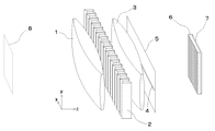
図1に本発明請求項1の立体像撮影装置の光学系の斜視図を示す。なお以下の各実施例はその光学系のみを表し、光学系を収納するケースや構造材は省略する。本実施例は対物レンズ(凸レンズ)1と、反射面を平行にして、反射面に垂直な方向に並んだダブプリズムの列2と、第2の凸レンズ3と、水平スリット4を有する遮光板5と、面上にシリンドリカルレンズが並んでなるレンチキュラーレンズ6と、撮像面7を持つ撮像手段とからなる。ここでスリット4をx軸と平行に、xz面が水平面になるように直交座標をとると、ダブプリズムの反射面はyz面と平行であり、反射面を外側に向けて対をなしたものがx軸と平行に並んでいる。ダブプリズムは同じ向きに並んだものでも基本的な機能は変わらないが、このように対をなして置くことで被写体からの光線を効率よく利用でき好ましい。さらに相対するダブプリズムの平行面の間には遮光板9が置かれ、隣接するダブプリズムから漏れる光線が迷光となって画質を低下させるのを防いでいる。図中ではダブプリズム間に隙間があるように見えるが、実際には隙間なく並べられるのが好ましい。またレンチキュラーレンズ6はy軸と平行なシリンドリカルレンズがx方向に並んだものとなる。視野角の広い立体像を撮影するためには、対物レンズ1と凸レンズ3はその焦点距離に対してx方向の幅が広いものを使用するのが好ましい。このようなレンズは通常大型かつ肉厚で高価なものとなるが、フレネルレンズを使うことで安価にすることができる。撮像手段は感光フィルムや写真乾板あるいはCCDなどの撮像素子であり、感光フィルムや写真乾板では撮像面7は感光面を表す。感光フィルムや写真乾板を用いて撮影する場合にはさらに露光を制御する手段が必要があるが、これには遮光板5に近接して水平スリット4を開閉するシャッターを設けるか、レンチキュラーレンズ6の前面にフォーカルプレーンシャッターを設けるなどすればよい。
【0034】
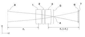
まず対物レンズ1の焦点距離f1と第2の凸レンズ3の焦点距離f2が等しい請求項2について説明する。図2にxz面の平面図を示す。撮像面7は凸レンズ3からf2だけ離れた位置に置かれ、対物レンズ1からf1だけ離れた位置に被写体のピント面8が存在する。ピント面8上で光軸(対物レンズ1と凸レンズ3の中心軸)からaだけ離れた点から発する光は対物レンズ1で光軸とtanθ=−a/f1である角度θをなす平行光に変換され、ダブプリズムの機能によって角度が反転され、光軸と角度−θをなす平行光になり、さらに凸レンズ3からf2だけ離れた撮像面7上で光軸からf2tan(−θ)だけずれた位置に達するが、f1=f2であるのでf2tan(−θ)=−f1tanθ=aとなる。このようにして撮像面7にはピント面8の等倍像が投影されるが、このとき被写体から発する光線の角度α,βと、同光線撮像面に達する際の入射角α’,β’は符号が逆で大きさも同程度となっている。両角度の大きさの違いはダブプリズムの大きさに依存しており、ダブプリズムが十分小さければ両角度はほとんど等くなる。この光線はレンチキュラーレンズ6を通って撮像面7に投影されるが、この様子を図4の部分拡大図を使ってさらに説明する。撮像面7はレンチキュラーレンズ6から各シリンドリカルレンズの焦点距離にほぼ等しい距離だけ離れているため、撮像面7には各シリンドリカルレンズに入射する光線の角度分布に対応するものが、それぞれのシリンドリカルレンズに対応する像として形成される。厳密にはレンチキュラーレンズ6と撮像面7の距離がシリンドリカルレンズの焦点距離に等しいときに各投影像は入射する光線の角度分布となり、このとき最も焦点深度が深い立体像が得られる。逆にレンチキュラーレンズ6と撮像面7の距離をシリンドリカルレンズの焦点距離とは若干異なるものとすることにより、特定のピント面を有する立体像を得ることができる。ただこの距離をシリンドリカルレンズの焦点距離と大きく異なるものとすると焦点深度が浅くなりすぎて好ましくない。
【0035】
図3にyz面の平面図を示し鉛直面内での機能を説明する。xz面内と同様に対物レンズ1と凸レンズ3によって8の位置の像が撮像面7に投影される。ここでダブプリズム列2とレンチキュラーレンズ6はyz面内で特別な機能を有さないため投影像は平面的な像となる。この際、遮光板5無しでは極めて焦点深度が浅い像となるが、立体像はある程度深い焦点深度がなければ平面像に対する優位性が無く、存在価値が無くなって好ましくない。このため水平スリット4を有する遮光板5で光線を絞り、焦点深度を稼ぐことが重要である。本実施例では遮光板5は凸レンズ3のレンチキュラーレンズ6側に置かれているが、被写体からレンチキュラーレンズ6までのいずれの位置に置かれてもよい。水平スリット4の位置が観測者の目の位置を決めるもので、これによって近くにあるものが大きく、遠くのものが小さく見える平面像の遠近感が決定される。
【0036】
本立体像撮影装置によって撮影された立体像は、特願2002−112824に記載されている負の線描立体像にあたり、同明細書に示された立体像表示装置によって表示することができる。該立体像を表示する装置の一例を図10に示す。本装置はレンチキュラーレンズ35と立体像を記録した面34からなる。記録面34は実際には印画紙、フィルムあるいは同様の像を表示する液晶パネルなどである。これらは図10左に示したように重ねられるが、このとき撮影像の各シリンドリカルレンズに対応する短冊状の各像に対し、レンチキュラーレンズ35の各シリンドリカルレンズが1対1で対応する。請求項2による等倍の撮影像についてはレンチキュラーレンズ35と記録面34の関係は撮影装置におけるレンチキュラーレンズ6と撮像面7の関係と全く同じになるため、撮影時と同じレンチキュラーレンズを使って表示ができるメリットがある。これを利用すればレンチキュラーレンズの平面の側に感光剤を塗布し、これを図1のレンチキュラーレンズ6と撮像面7として立体像を撮影し、これをポジ現像してそのまま表示装置に利用することもできる。
【0037】
図1の装置において、対物レンズの焦点距離f1と第2の凸レンズの焦点距離f2が異なる場合は、撮像面7と第2の凸レンズの間隔をf2とすれば、撮像面7にはf2/f1に拡大ないし縮小された像が投影され、拡大撮影ないし縮小撮影をすることができる。この場合も撮影された像は上記した構造の表示装置で表示することが可能な立体像である。しかしながらこのとき、図2におけるα,βがα’,β’とほぼ等しくなるという関係が崩れるため、表示装置に使うレンチキュラーレンズは撮影時のレンチキュラーレンズとはシリンドリカルレンズの形状やピッチも厚さも異なるものになる。
【0038】
表示装置に使うレンチキュラーレンズ35のシリンドリカルレンズ形状とピッチ及び厚さは、比較的容易な計算で求めることができるが、さらに工夫を施した請求項3,4の立体像撮影装置を用いれば、撮影時のレンチキュラーレンズとピッチの等しいレンチキュラーレンズで表示することができる。
【0039】
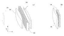
図7は被写体を拡大撮影する請求項4の立体像撮影装置の光学系である。さらに本装置のxz面における平面図を図8に示した。本装置では第2の凸レンズ17の焦点距離f2は対物レンズ14の焦点距離f1より長く、レンチキュラーレンズ19の前に第3の凸レンズ18が置かれている。凸レンズ17と凸レンズ18の距離L1はf2より小さく、凸レンズ18の焦点距離f3は数1で表される。被写体のピント面21は対物レンズ14からf1だけ離れた位置に存在する。図8の平面図において被写体よりz軸に平行に進む光線22は、凸レンズ17を出た時点で広がる光線になるが、凸レンズ18の働きで再びz軸に平行な光線23になってレンチキュラーレンズ19に入射する。このようにして被写体からz軸に平行に発した光線がレンチキュラーレンズ19に入射する際にもz軸に平行になることにより、撮影された立体像は撮影時のレンチキュラーレンズとピッチの等しいレンチキュラーレンズで再生できるものとなる。なお凸レンズ18により焦点面が移動するため、凸レンズ17と撮像面までの距離は数2で表されるL2に等しくするのが好ましい。
【0040】
ここで角度が保存されるのはz軸に平行な光線のみで、それ以外の光線は像の拡大に伴い角度が変わってしまうので、表示時のレンチキュラーレンズの厚さはそれに伴って変える必要がある。簡単には撮影時のレンチキュラーレンズの厚さに像の倍率の逆数をかけたものとすればよい。さらにこれに伴ってシリンドリカルレンズの曲率(焦点距離)も立体像とシリンドリカルレンズの距離がその焦点距離にほぼ等しくなるように変えるのが好ましい。
【0041】
以上はf1<f2で拡大撮影する装置について説明したが、請求項3のようにf1>f2であれば縮小撮影の装置となる。図9は縮小像を撮影する請求項3の立体像撮影装置の平面図である。本装置では第2の凸レンズ27の焦点距離f2は対物レンズ24の焦点距離f1より短く、レンチキュラーレンズ29の前には凹レンズ28が置かれている。ここで凹レンズ28の負の焦点距離f3は数1で表され、距離L2は数2で表される。同図において被写体よりz軸に平行に進む光線32は、凸レンズ27を出た時点で集束する光線になるが、凹レンズ28の働きで再びz軸に平行な光線33になってレンチキュラーレンズ29に入射する。本装置を用いれば撮影時のレンチキュラーレンズとピッチの等しいレンチキュラーレンズで再生できる立体像が撮影できる。
【0042】
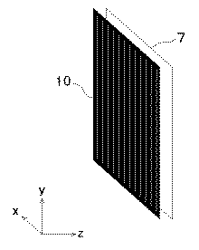
図1や図7の立体像撮影装置において、レンチキュラーレンズ6や19はy軸に平行なスリットがx方向に並んだスリット板に置き換えることができる。図5はその様子を示したものである。スリット板10はy軸に平行なスリットが等間隔でx方向に並んだもので、これが図1や図7のレンチキュラーレンズの代わりに撮像面の前に置かれる。スリット板10と撮像面7は平行で、その間隔とスリット板10のスリットのピッチの比が、第2の凸レンズとスリット板10の距離と同レンズの幅の比に等しくすれば、撮像面の全面を有効に使うことができる。またスリット板10と撮像面7の間隔を等しく保つためには、両者の間に透明な板を置き、スリット板10と撮像面7をその透明板に密着させて位置決めをする方法がある。この場合スリット板10は、該透明板の片面にスリット列を有する遮光パターンを印刷するなりして遮光層を形成したもので代用することができ、この場合は該遮光層がスリット板であると見なすことができる。
【0043】
レンチキュラーレンズを使った請求項1〜4の立体像撮影装置では、シリンドリカルレンズの集束作用を使って入射光の角度分布に対する像を作るのに対し、スリット板を用いる請求項5〜8の立体像撮影装置においては、ピンホールレンズの原理によって同様の像を形成する。後者では焦点深度が深い像が得られる一方、像の解像度がスリットの幅で決まってしまうためスリット幅を十分狭くとる必要があり、このためレンチキュラーレンズを使う前者に比べて使える光の量が著しく少なくなるという問題がある。このため動きのある被写体のように露光時間を長くとれない場合には、レンチキュラーレンズを用いる請求項1〜4の立体像撮影装置の方が適している。
【0044】
請求項1〜4の立体像撮影装置において、より焦点深度の深い立体像を撮影するためには、図6に示すようなレンチキュラーレンズ11を用いる方法がある。レンチキュラーレンズ11は、シリンドリカルレンズ12と遮光部13が交互に並んだもので、シリンドリカルレンズ12の並ぶ間隔はレンチキュラーレンズ6や19と同じである。このように有効なシリンドリカルレンズの幅を減少する事で焦点深度は深くなり、レンズの収差も小さくできるので画質の向上も期待できる。一方使用する光量は減少するが、スリット板を使う時のような著しい減少ではないので、若干感度が低下する程度の副作用で済む。
【0045】
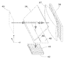
図11に本発明請求項9の立体像撮影装置の光学系の斜視図を示す。本実施例は屋根状に直交する反射面がその稜線に垂直な方向に多数並んでなる反射面群38、凸レンズ37、ハーフミラー36、水平スリット39を有する遮光板40、面上にシリンドリカルレンズが並んでなるレンチキュラーレンズ41と、撮像面42を持つ撮像手段とからなる。ここで反射面群の稜線をy軸と平行に、並ぶ方向をx軸と平行にとり、xz面が水平面になるように直交座標をとると、反射面群38はxz面と垂直でz軸に対して±45度をなす短冊状の反射面が交互に並んだもので、凸レンズ37は反射面群38の前に平行に置かれ、ハーフミラー36はx軸と平行でz軸に対して45度をなして傾斜し、遮光板40、レンチキュラーレンズ41、撮像面42はxz面と平行である。被写体からの光は図の太線矢印の経路で撮像面に投影される。すなわちまずハーフミラー36を透過して凸レンズ37に入り、これを通過して反射面群38で反射し、再び凸レンズ37を通った後ハーフミラー36で反射して水平スリット39を通ってレンチキュラーレンズ41を通じて撮像面42に投影される。反射面群38には、例えば頂角が直角である階段状の形状をした面に金属メッキなどを施して反射面としたものなどが使われる。またレンチキュラーレンズ41はz軸と平行なシリンドリカルレンズがx方向に並んだものとなる。撮像手段42に感光フィルムや写真乾板を用いる場合には露光を制御する手段が必要があるが、これには遮光板40に近接して水平スリット39を開閉するシャッターを設けるか、レンチキュラーレンズ41の前面にフォーカルプレーンシャッターを設けるなどすればよい。
【0046】
まず水平面内の機能について説明する。図12にxz面の平面図を示す。凸レンズ37からその焦点距離f1だけ離れた位置に被写体のピント面43が存在し、ピント面43上で光軸(凸レンズ37の中心軸)からaだけ離れた点から発する光は凸レンズ37で光軸とtanθ=−a/f1である角度θをなす平行光に変換され、反射面群38の直交する反射面の機能によって向きが反転され、逆方向に進む平行光になり、再び凸レンズ37を通って集束され、ピント面43上の同じ位置に戻ってゆく。ここで反射面群38の各反射面対の幅が十分小さければ、被写体から発する光はその位置だけでなく、方向までほとんど変わらず戻ってくることになる。そこで凸レンズ37から被写体側に戻ってくる光をハーフミラー36を使って反射し、ピント面43に当たる位置、すなわち凸レンズ37からハーフミラー36を反射する光路にそってf1だけ離れた位置にレンチキュラーレンズ41と撮像面42を置けば、そこに光線の位置と角度分布が保たれる像が投影されることになる。本装置における反射面群38の機能は図1におけるダブプリズム列の機能と同じであり、撮像面42には図1の装置と同様の理由で同じ性質の立体像が投影されることになる。
【0047】
図13にyz面の平面図を示し鉛直面内での機能を説明する。xz面内と同様に凸レンズ37を二度通過して43の位置の像が撮像面42に投影される。ここで反射面群38は平面鏡と同様の機能となり、投影像は平面的な像となるが、遮光板40無しでは極めて焦点深度が浅い像となってしまう。このため図1の装置と同様に水平スリット39を有する遮光板40で光線を絞り、焦点深度を稼いでいる。本実施例では遮光板40はハーフミラー36からレンチキュラーレンズ41に向かう位置に置かれているが、被写体からハーフミラー36までの間に置かれてもよい。水平スリット39の位置によって近くにあるものが大きく、遠くのものが小さく見える平面像の遠近感が決定されるので、撮影した立体像を観測する際の条件などを考慮してその位置を決める必要がある。
【0048】
図14は本発明請求項11の立体像撮影装置の光学系の斜視図である。本実施例は図11の反射面群38を、y軸方向の幅が狭く線状になった反射面群44に置き換え、遮光板40を省いたものである。図15にyz面の平面図を示すように反射群44が水平スリットの役割を果たし、焦点深度を深めるとともに遠近感を作っているので水平スリットは不要になる。
【0049】
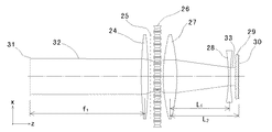
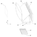
一枚の凸レンズ37で構成される図11や図14の立体像撮影装置は撮像面42上に等倍像を投影するものであり、拡大像や縮小像を撮影することはできない。これに対して複数の凸レンズを使用する請求項13によれば、等倍像に限らず拡大像や縮小像をも撮影することができる。図16は請求項13による立体像撮影装置の光学系の斜視図である。被写体からの光はまず対物レンズ45を通り、ハーフミラー46を透過してから反射面群47で反射し、ハーフミラー46で反射して第2の凸レンズ48に入り、これを通過後水平スリット49を通ってレンチキュラーレンズ51を通じて撮像面52に投影される。対物レンズ45と第2の凸レンズ48は反射面群47から等しい光路長だけ離れた位置にあり、対物レンズ45とピント面53の距離は対物レンズ45の焦点距離f1に等しく、第2の凸レンズ48と撮像面52の距離は凸レンズ48の焦点距離f2に等しい。先に説明したとおり反射面群47は図1の装置のダブプリズム列2と同様の機能を有し、本装置は対物レンズ45と第2の凸レンズ48によって図1の装置と同様の機能を持つ立体像撮影装置となり、撮像面52には倍率f2/f1の像が投影される。
【0050】
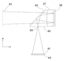
図16の立体像撮影装置においても、請求項11と同様に反射面群47を、y軸方向の幅が狭く線状になった反射面群に置き換えれば、遮光板50を省くことができる。さらにこのような反射面群を使う場合には、図17に示すように反射面群55を傾斜して置き、ハーフミラーを用いない装置とすることが可能である。本装置ではピント面59の前後にある被写体からの光は対物レンズ54を通り、反射面群55で反射して第2の凸レンズ56に入り、これを通過してレンチキュラーレンズ57を通じて撮像面58に投影される。図18はyz面の平面図である。図18から解るように反射面群55が対物レンズ54及び凸レンズ56と平行でなくとも、反射面群55は幅を狭くすることでこれを反射する光線の対物レンズ54と凸レンズ56までの光路長をほぼ等しくすることができ、請求項13,14と同様に立体像を撮影することができる。正確には本装置の撮影像は図14の装置の撮影像と鏡像の関係にあり、かつ反射面群55の反射光量が反射角によって異なるため、撮影像には図18の矢印60に示す方向に明るさが低下する不均一を生じる。従って実際の撮影では、この不均一を打ち消す濃度勾配を有する減光フィルターをレンチキュラーレンズ57の前に置いて撮影するのが好ましい。
【0051】
以上説明した請求項13,14,15の立体像撮影装置において、対物レンズの焦点距離f1と第2の凸レンズの焦点距離f2が等しい場合には等倍像を撮影する装置となり、撮影像は撮影に用いたレンチキュラーレンズと同じレンチキュラーレンズを用いて表示することができる(請求項16)。一方f1とf2が異なる場合は、f2/f1に拡大ないし縮小された像が投影されるが、この際には先に請求項3,4で説明したのと同様に、レンチキュラーレンズの前に凹レンズないし第3の凸レンズを置くことで、撮影に用いたレンチキュラーレンズと同じピッチのレンチキュラーレンズを用いて表示することができる撮影像を撮影することができる(請求項17,18)。
【0052】
さらに請求項13〜18の立体像撮影装置においては、レンチキュラーレンズを平行なスリットが多数並んだスリット板に置き換えることができる(請求項19〜24)。
【0053】
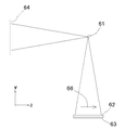
本発明の請求項25,26は、最もシンプルな装置で立体像を撮影することを追求したものである。請求項25の立体像撮影装置の光学系を図19に示す。本装置は直交する微小な反射面が線状に並んだ反射面群61とレンチキュラーレンズ62と撮像面63を有する撮像手段からなり、被写体からの光は反射面群61で反射してレンチキュラーレンズ62を通して撮像面63に投影される。これらを波線で示したような暗箱65に入れて反射面61からの反射光以外の光線がレンチキュラーレンズに入らないようにするだけで立体像の撮影ができる装置となる。ピント面64と撮像面63は反射面61から等しい距離を離れた位置に存在する。
【0054】
図20はy=zの平面(y軸及びz軸と45度をなす平面)への投影図である。反射面群61を構成する微小な反射面はこの面と直交しており、同面内で頂角が90度である反射面対が並んだものとなっている。ピント面64から発する光は反射面群61の反射面対で反射して撮像面63に達するが、直交する2面で反射する光は平行で逆向きになり、撮像面63上での該光線のx座標とピント面64上のx座標とのずれdは該反射面対の幅以下になる。従って撮像面には該反射面対の幅と同程度の解像度でピント面64の像が結ばれることになる。例えば該反射面対の幅が0.1ミリであれば、原理的には解像度0.1ミリ程度の像が得られるわけであるが、実際には反射面対の角度精度にも依存するため、実際の解像度はこれより若干劣るものとなる。このように本平面内においては撮像面63に向かう光線はピント面64における位置と角度が再現されているので、撮像面63の前に置かれたレンチキュラーレンズ62によって角度分布の像に変換されて撮像面63に投影される。
【0055】
図21は本装置のyz面の平面図である。この面内においては反射面群61とレンチキュラーレンズ62は特別な機能を示さず、ピンホールカメラの原理によってピント面64の等倍像が撮像面に投影される。投影像の解像度は反射面群61の幅の2倍になり、例えば反射面群61の幅が0.1ミリなら投影像の解像度は0.2ミリということになる。さらに投影像には反射光量の反射角依存性に起因する明るさの不均一が存在し、明るさは矢印66の方向に減少するため、実際の撮影では、この不均一を打ち消す濃度勾配を有する減光フィルターをレンチキュラーレンズ62の前に置いて撮影するのが好ましい。
【0056】
また図14の装置から凸レンズ37を除いても請求項25の他の実施例とすることができる。この場合にはハーフミラーによる光線の損失がある一方で、図19の実施例に存在する明るさの不均一が存在しないというメリットがある。
【0057】
さらに請求項25の立体像撮影装置において、レンチキュラーレンズを平行なスリットが多数並んだスリット板に置き換えれば、同様な機能を有する請求項26の立体像撮影装置となる。
【0058】
請求項25,26の装置によって撮影された立体像は、請求項1〜24の立体像撮影装置で撮影された立体像と同様、特願2002−112824に記載されている負の線描立体像にあたり、同様の立体像表示装置によって表示することができる。
【0059】
【発明の効果】
本発明のによれば簡単な装置で立体像を撮影することができ、さらに撮影した立体像は簡単な表示装置で見ることができる。この際には特殊な眼鏡やビュアーを使う必要がないので、不特定の複数の人間が同時に鑑賞することができる。
【図面の簡単な説明】
【図1】請求項1および請求項2による立体像撮影装置の実施例である。
【図2】図1の実施例を上方から見た平面図である。
【図3】図1の実施例を側面から見た平面図である。
【図4】図1の実施例の撮影原理を説明する部分拡大図である。
【図5】本発明の請求項5〜8,10,12,19〜24,26に使われるスリット板の説明図である。
【図6】本発明の請求項1〜4,9,11,13〜18,25に使われるレンチキュラーレンズの一例を説明する図である。
【図7】本発明の請求項4による立体像撮影装置の実施例である。
【図8】図7の実施例を上方から見た平面図である。
【図9】本発明の請求項3による立体像撮影装置の実施例の平面図である。
【図10】本発明による撮影像を表示する立体像表示装置の一例である。
【図11】本発明の請求項9による立体像撮影装置の実施例である。
【図12】図11の装置の原理を説明する平面図である。
【図13】図11の実施例を側面から見た平面図である。
【図14】本発明の請求項11による立体像撮影装置の実施例である。
【図15】図14の実施例を側面から見た平面図である。
【図16】本発明の請求項13による立体像撮影装置の実施例である。
【図17】本発明の請求項15による立体像撮影装置の実施例である。
【図18】図17の実施例を側面から見た平面図である。
【図19】本発明の請求項25による立体像撮影装置の実施例である。
【図20】図19の装置の原理を説明する平面図である。
【図21】図19の実施例を側面から見た平面図である。
【符号の説明】
1,14,24 ・・・ 対物レンズ(凸レンズ)
2,15,26 ・・・ ダブプリズム列
3,17,27 ・・・ 第2の凸レンズ
4 ・・・ 水平スリット
5,16,25 ・・・ 水平スリットを有する遮光板
6,19,29,35 ・・・ レンチキュラーレンズ
7,20,30 ・・・ 撮像面
8,21,31 ・・・ ピント面
9 ・・・ 遮光板
10 ・・・ スリット板
11 ・・・ シリンドリカルレンズの間に遮光部を有するレンチキュラーレンズ
12 ・・・ シリンドリカルレンズ
13 ・・・ 遮光部
18 ・・・ 第3の凸レンズ
22,32 ・・・ ピント面からz軸に平行に進む光線
23,33 ・・・ レンチキュラーレンズに入射する光線
28 ・・・ 凹レンズ
34 ・・・ 撮影像
36,46 ・・・ ハーフミラー
37 ・・・ 凸レンズ
38,47 ・・・ 反射面群
39,49 ・・・ 水平スリット
40,50 ・・・ 水平スリットを有する遮光板
41,51,57,62 ・・・ レンチキュラーレンズ
42,52,58,63 ・・・ 撮像面
43,53,59,64 ・・・ ピント面
44,55,61 ・・・ 微小な反射面が並んだ反射面群
45,54 ・・・ 対物レンズ(凸レンズ)
48,56 ・・・ 第2の凸レンズ
60,66 ・・・ 像の明るさの勾配を表す矢印
65 ・・・ 暗箱[0001]
TECHNICAL FIELD OF THE INVENTION
The present invention relates to an apparatus for capturing a three-dimensional image.
[0002]
[Prior art]
Conventionally, in order to shoot and display a stereoscopic image, two images are taken with two cameras placed at a predetermined distance in the horizontal direction, and the two-dimensional images are taken using glasses using polarizing glass or color filters, or a special viewer. There are a method in which a photographed image can be seen by each of the right and left eyes, and a method in which a lenticular lens is used so as to be seen from different angles.
[0003]
In addition, as a method of shooting and displaying a stereoscopic image that can be viewed without using a special viewer, Integra Integrate uses a group of convex lenses arranged in a plane to take a picture of the subject and reproduces it using the same convex lens group Photography and holograms.
[0004]
[Problems to be solved by the invention]
Things that must be viewed using glasses or a viewer are extremely inconvenient to provide stereoscopic images to unspecified people. In addition, when multiple images are viewed from different angles using a lenticular lens, several images can be switched depending on the viewing angle, so depending on the viewing position, a double image may be seen or the observer may move. However, there is also a problem that an unnaturalness may be felt when viewing the image, and the angle range in which good observation can be performed is relatively narrow.
[0005]
In addition, integral photography has a problem that it is not easy to manufacture a photographing machine, and if it is used as it is, it becomes an unnatural three-dimensional image in which the perspective is reversed. It is difficult to enjoy.
[0006]
In order to solve these problems, the present inventor has devised a method of capturing and displaying a stereoscopic image different from the conventional method, and has already filed an application in Japanese Patent Application No. 2002-112824. Invented is a photographing device that can more easily photograph a three-dimensional image that can be displayed on the display device.
[0007]
[Means for Solving the Problems]
Claim 1 of the present invention is directed to a row of Dove prisms arranged in a direction perpendicular to the reflection surface with the reflection surface parallel, and a position at an equal distance from the Dove prism row so as to sandwich the Dove prism row. A lenticular lens in which an objective lens (convex lens) and a second convex lens placed at a position, a cylindrical lens having an axis parallel to the entrance surface and the reflection surface of the Dove prism are arranged in parallel with the Dove prism array, and An imaging means having a surface parallel to the lenticular lens and spaced at an interval substantially equal to the focal length of the cylindrical lens, and a light-shielding plate having a horizontal slit perpendicular to the reflection surface of the Dove prism, the image of the subject is formed. A device projected onto the imaging means through an objective lens, the Dove prism array, a second convex lens, and the lenticular lens, wherein the horizontal slit It is placed between the object and the objective lens, between the objective lens and the Dove prism array, between the Dove prism array and the second convex lens, or between the second convex lens and the lenticular lens to regulate light rays. It is a three-dimensional image photographing device characterized by the above.
[0008]
According to a second aspect of the present invention, the focal length of the objective lens (convex lens) and the second convex lens are equal, and the distance between the second convex lens and the imaging surface is equal to the focal length. Is a three-dimensional image photographing apparatus.
[0009]
According to a third aspect of the present invention, there is provided the stereoscopic image photographing apparatus according to the first aspect, wherein the focal length of the second convex lens is shorter than the focal length of the objective lens (convex lens), and the reduced image of the subject is photographed. When a concave lens is placed in front of the lens and the focal length of the objective lens is f1 and the focal length of the second convex lens is f2, the distance L1 between the second convex lens and the concave lens is smaller than f2, and the focal length of the concave lens is f3 (negative value) is represented by Expression 1, and the distance L2 between the second convex lens and the imaging surface is represented by Expression 2, and is a stereoscopic image photographing apparatus.
[0010]
According to a fourth aspect of the present invention, there is provided the stereoscopic image photographing apparatus according to the first aspect, wherein the focal length of the second convex lens is longer than the focal length of the objective lens (convex lens), and the enlarged image of the subject is photographed. When a third convex lens is placed in front of the lens and the focal length of the objective lens is f1 and the focal length of the second convex lens is f2, the distance L1 between the second convex lens and the third convex lens is smaller than f2, A focal length f3 of the third convex lens is represented by Expression 1, and a distance L2 between the second convex lens and the imaging surface is represented by Expression 2.
[0011]
According to a fifth aspect of the present invention, a row of Dove prisms arranged in a direction perpendicular to the reflection surface with the reflection surface parallel to each other, and a position at an equal distance from the Dove prism row so as to sandwich the Dove prism row An objective lens (convex lens) and a second convex lens, a slit plate in which slits parallel to an entrance surface and a reflection surface of the Dove prism are arranged in parallel with the Dove prism row, and an imaging surface thereof is the slit plate. And a light-shielding plate having a horizontal slit perpendicular to the reflection surface of the Dove prism, and the image of the object is formed by the objective lens, the Dove prism array, the second convex lens, and the slit plate. A horizontal slit is provided between the object and the objective lens, or between the objective lens and the Dove prism array, or between the Dove prism array and the second convex lens, or A three-dimensional image photographing apparatus characterized by being brought into either of the two convex lens and the slit plates and to regulate the light beam.
[0012]
According to a sixth aspect of the present invention, the objective lens (convex lens) and the second convex lens have the same focal length, and the distance between the second convex lens and the imaging surface is equal to the focal length. Is a three-dimensional image photographing apparatus.
[0013]
According to a seventh aspect of the present invention, there is provided the stereoscopic image photographing apparatus according to the fifth aspect, wherein the focal length of the second convex lens is shorter than the focal length of the objective lens (convex lens), and the reduced image of the subject is photographed. When a concave lens is placed in front of the plate and the focal length of the objective lens is f1 and the focal length of the second convex lens is f2, the distance L1 between the second convex lens and the concave lens is smaller than f2, and the focal length of the concave lens is f3 (negative value) is represented by Expression 1, and the distance L2 between the second convex lens and the imaging surface is represented by Expression 2, and is a stereoscopic image photographing apparatus.
[0014]
An eighth aspect of the present invention is the stereoscopic image photographing apparatus according to the fifth aspect, wherein the focal length of the second convex lens is longer than the focal length of the objective lens (convex lens), and the enlarged image of the subject is photographed. When a third convex lens is placed in front of the plate and the focal length of the objective lens is f1 and the focal length of the second convex lens is f2, the distance L1 between the second convex lens and the third convex lens is smaller than f2, A focal length f3 of the third convex lens is represented by Expression 1, and a distance L2 between the second convex lens and the imaging surface is represented by Expression 2.
[0015]
According to a ninth aspect of the present invention, there is provided a reflection surface group in which a plurality of reflection surfaces orthogonal to a roof shape are arranged in a direction perpendicular to the ridgeline, a convex lens placed in front of the reflection surface group, and A half-mirror placed in front of it, a light-shielding plate having a horizontal slit parallel to the direction in which the reflection surface groups are arranged, a lenticular lens in which cylindrical lenses are arranged in the same direction as the reflection surface groups, and imaging of the same Imaging means having a surface parallel to the lenticular lens and spaced at an interval substantially equal to the focal length of the cylindrical lens, wherein light rays from an object pass through or reflect through the half mirror, pass through the convex lens, and reflect through the reflecting surface. An apparatus which is reflected by a group, passes through the convex lens again, reflects or transmits through the half mirror, and is projected through the lenticular lens to the imaging means, wherein Tsu DOO is a stereographic image capturing apparatus characterized by regulating the is in light placed anywhere between between to half-mirror and the lenticular lens of the subject and the half mirror.
[0016]
Claim 10 of the present invention is a reflection surface group orthogonal to the roof shape, a plurality of reflection surface groups arranged in a direction perpendicular to the ridgeline, a convex lens placed in front of the reflection surface group, and further, the convex lens A half mirror placed inclining in front, a light shielding plate having a horizontal slit parallel to the direction in which the reflection surface group is arranged, a slit plate in which a number of parallel slits are arranged in the same direction as the reflection surface group, The imaging surface is composed of imaging means placed in parallel with the slit plate, and the light from the subject passes through or reflects through the half mirror, passes through the convex lenses, is reflected by the reflection surface group, passes through the convex lenses again, An apparatus which reflects or transmits the half mirror and projects the image on the imaging means through the slit plate, wherein the horizontal slit is placed between the subject and the half mirror or between the half mirror and the slit plate. Rays A three-dimensional image photographing apparatus characterized by win.
[0017]
Claim 11 of the present invention is a reflection surface group in which a number of minute reflection surfaces orthogonal to the roof shape are arranged in a line in a direction perpendicular to the ridge line, and a convex lens placed in front of the reflection surface group. A half mirror that is further inclined before the convex lens, a lenticular lens in which cylindrical lenses are arranged in the same direction as the reflecting surface group, and an imaging surface of the cylindrical lens in parallel with the lenticular lens. Imaging means arranged at an interval substantially equal to the focal length, wherein light rays from the subject pass through or reflect through the half mirror, pass through the convex lenses, are reflected by the reflecting surface group, pass through the convex lenses again, and pass through the convex lens. A three-dimensional image photographing apparatus characterized in that the light is reflected or transmitted through a mirror, and is projected on the imaging means through the lenticular lens.
[0018]
A twelfth aspect of the present invention is directed to a reflection surface group in which a plurality of minute reflection surfaces orthogonal to a roof shape are arranged in a line in a direction perpendicular to the ridge line, and a convex lens disposed in front of the reflection surface group. A half mirror that is further inclined in front of the convex lens, a slit plate in which a number of parallel slits are arranged in the same direction as the reflection surface group, and an imaging surface in which the imaging surface is placed parallel to the slit plate. After the light from the subject passes or reflects through the half mirror, passes through the convex lens, is reflected by the group of reflecting surfaces, reflects or transmits the half mirror again through the convex lens, and passes through the slit plate. A three-dimensional image photographing apparatus characterized by being projected through the imaging means.
[0019]
Claim 13 of the present invention, a reflection surface group orthogonal to the roof shape, a plurality of reflection surface groups arranged in a direction perpendicular to the ridgeline, a half mirror that is inclined and placed in front of the reflection surface group, An objective lens (convex lens) placed on one surface of the half mirror, a second convex lens placed on the other surface of the half mirror, and a direction parallel to the direction in which the reflection surface group is arranged. A light-shielding plate having a horizontal slit, a lenticular lens in which cylindrical lenses are arranged in the same direction as the reflection surface group, and an imaging surface thereof are placed in parallel with the lenticular lens with an interval substantially equal to the focal length of the cylindrical lens. A light beam from a subject passes through the objective lens and is reflected or reflected by the half mirror, then is reflected by the reflecting surface group, is reflected or transmitted by the half mirror again, and is reflected by the second convex lens. An image projected through the lenticular lens onto the imaging means, wherein the horizontal slit is placed between the subject and the half mirror or between the half mirror and the lenticular lens to restrict light rays. A three-dimensional image photographing apparatus characterized in that:
[0020]
According to a fourteenth aspect of the present invention, there is provided a reflection surface group in which a number of minute reflection surfaces orthogonal to a roof shape are linearly arranged in a direction perpendicular to the ridge line, and the reflection surface group is inclined and placed in front of the reflection surface group. A half mirror, an objective lens (convex lens) placed on one surface of the half mirror, a second convex lens placed on the other surface of the half mirror, and the reflection surface group. A lenticular lens in which cylindrical lenses are arranged in the same direction, and imaging means having an imaging surface parallel to the lenticular lens and spaced at an interval substantially equal to the focal length of the cylindrical lens, and a light beam from an object is used as an object. After transmitting or reflecting through the half mirror through the lens, the light is reflected by the reflection surface group, reflected or transmitted again through the half mirror, passes through the second convex lens, passes through the lenticular lens, and returns to the photographic lens. A three-dimensional image photographing apparatus characterized by being projected to the means.
[0021]
According to a fifteenth aspect of the present invention, there is provided an object in which a plurality of minute reflecting surfaces orthogonal to a roof shape are arranged in a line in a direction perpendicular to the ridge line, and an equal distance from the reflecting surface group. A lens (convex lens), a second convex lens, a lenticular lens in which cylindrical lenses are arranged in the same direction as the reflecting surface group, and an interval whose imaging surface is parallel to the lenticular lens and substantially equal to the focal length of the cylindrical lens. Light from an object is reflected by the group of reflecting surfaces through the objective lens, passes through the second convex lens, and is projected onto the imaging means through the lenticular lens. This is a three-dimensional image photographing device that is a feature.
[0022]
According to a sixteenth aspect of the present invention, the objective lens (convex lens) and the second convex lens have the same focal length, and the distance between the second convex lens and the imaging surface is equal to the focal length. , 15.
[0023]
A seventeenth aspect of the present invention is the stereoscopic image photographing apparatus according to the thirteenth, fourteenth, or fifteenth aspect, wherein the focal length of the second convex lens is shorter than the focal length of the objective lens (convex lens), and the reduced image of the subject is photographed. Further, when a concave lens is placed in front of the lenticular lens and the focal length of the objective lens is f1 and the focal length of the second convex lens is f2, the distance L1 between the second convex lens and the concave lens is smaller than f2. A focal length f3 (negative value) of the concave lens is represented by Expression 1, and a distance L2 between the second convex lens and the imaging surface is represented by Expression 2.
[0024]
The eighteenth aspect of the present invention is the stereoscopic image photographing apparatus according to the thirteenth, fourteenth, or fifteenth aspect, wherein the focal length of the second convex lens is longer than the focal length of the objective lens (convex lens), and the enlarged image of the subject is photographed. Further, when a third convex lens is placed before the lenticular lens, and the focal length of the objective lens is f1 and the focal length of the second convex lens is f2, the distance L1 between the second convex lens and the third convex lens is This is a stereoscopic image photographing apparatus characterized in that the focal length f3 of the third convex lens is smaller than f2, and the focal length f3 of the third convex lens is expressed by Expression 1, and the distance L2 between the second convex lens and the imaging surface is expressed by Expression 2.
[0025]
Claim 19 of the present invention is a reflective surface group orthogonal to the roof shape, a large number of reflective surface groups arranged in a direction perpendicular to the ridgeline, and a half mirror inclined and placed in front of the reflective surface group, An objective lens (convex lens) placed on one surface of the half mirror, a second convex lens placed on the other surface of the half mirror, and a direction parallel to the direction in which the reflection surface group is arranged. A light-shielding plate having a horizontal slit, a slit plate in which a number of parallel slits are arranged in the same direction as the reflection surface group, and imaging means having an imaging surface parallel to the slit plate; Is transmitted through or reflected by the half mirror through the objective lens, is reflected by the reflection surface group, is reflected or transmitted again by the half mirror, passes through the second convex lens, passes through the slit plate, and is projected onto the imaging means. Wherein the horizontal slit is A three-dimensional image photographing apparatus characterized by placed anywhere between to half mirror and the slit plates of Utsushitai a half mirror for restricting the light beam.
[0026]
According to a twentieth aspect of the present invention, there is provided a reflection surface group in which a number of minute reflection surfaces orthogonal to a roof shape are linearly arranged in a direction perpendicular to the ridgeline, and the reflection surfaces are inclined and placed in front of the reflection surface group. A half mirror, an objective lens (convex lens) placed on one surface of the half mirror, a second convex lens placed on the other surface of the half mirror, and a parallel slit. After a number of slit plates arranged in the same direction as the reflection surface group and an imaging means whose imaging surface is placed in parallel with the slit plate, light rays from an object pass through an objective lens and pass through or reflect through a half mirror. A three-dimensional image photographing apparatus, wherein the light is reflected by the reflection surface group, reflected or transmitted again through the half mirror, passes through the second convex lens, passes through the slit plate, and is projected onto the imaging means. is there.
[0027]
According to a twenty-first aspect of the present invention, there is provided an object in which a plurality of minute reflecting surfaces orthogonal to a roof shape are arranged in a line in a direction perpendicular to the ridge line, and an equal distance from the reflecting surface group. A lens (convex lens) and a second convex lens, a slit plate in which a number of parallel slits are arranged in the same direction as the reflection surface group, and imaging means having an imaging surface parallel to the slit plate; Is reflected by the group of reflecting surfaces through an objective lens, passes through a second convex lens, passes through the slit plate, and is projected onto the imaging means.
[0028]
According to a twenty-second aspect of the present invention, the objective lens (convex lens) and the second convex lens have the same focal length, and the distance between the second convex lens and the imaging surface is equal to the focal length. , 21.
[0029]
According to a twenty-third aspect of the present invention, there is provided the three-dimensional image photographing apparatus according to the nineteenth, twenty-first or twenty-first aspect, wherein the focal length of the second convex lens is shorter than the focal length of the objective lens (convex lens), and the reduced image of the subject is photographed. Further, when a concave lens is placed in front of the slit plate and the focal length of the objective lens is f1 and the focal length of the second convex lens is f2, the distance L1 between the second convex lens and the concave lens is smaller than f2. A focal length f3 (negative value) of the concave lens is represented by Expression 1, and a distance L2 between the second convex lens and the imaging surface is represented by Expression 2.
[0030]
According to a twenty-fourth aspect of the present invention, there is provided the three-dimensional image photographing apparatus according to the nineteenth aspect, wherein the focal length of the second convex lens is longer than the focal length of the objective lens (convex lens), and the enlarged image of the subject is photographed. Further, when a third convex lens is placed in front of the slit plate and the focal length of the objective lens is f1 and the focal length of the second convex lens is f2, the distance L1 between the second convex lens and the third convex lens is This is a stereoscopic image photographing apparatus characterized in that the focal length f3 of the third convex lens is smaller than f2, and the focal length f3 of the third convex lens is expressed by Expression 1, and the distance L2 between the second convex lens and the imaging surface is expressed by Expression 2.
[0031]
A twenty-fifth aspect of the present invention is directed to a reflection surface group in which a number of minute reflection surfaces orthogonal to a roof shape are linearly arranged in a direction perpendicular to the ridgeline, and a cylindrical lens is arranged in the same direction as the reflection surface group. A lenticular lens consisting of: and an imaging means whose imaging surface is parallel to the lenticular lens, and imaging means arranged at an interval substantially equal to the focal length of the cylindrical lens, light rays from a subject are reflected by the reflection surface group, A three-dimensional image photographing apparatus characterized in that the image is projected onto the imaging means through the lenticular lens.
[0032]
According to a twenty-sixth aspect of the present invention, there is provided a reflection surface group in which a number of minute reflection surfaces orthogonal to a roof shape are linearly arranged in a direction perpendicular to the ridge line, and parallel slits are formed in the same direction as the reflection surface group. It consists of a large number of slit plates and imaging means whose imaging surface is placed parallel to the slit plate. Light rays from a subject are reflected by the group of reflecting surfaces and projected onto the imaging means through the slit plates. A three-dimensional image photographing apparatus characterized in that:
[0033]
BEST MODE FOR CARRYING OUT THE INVENTION
FIG. 1 is a perspective view of an optical system of the three-dimensional image photographing apparatus of the present invention. In the following embodiments, only the optical system is shown, and a case and a structural material for housing the optical system are omitted. In this embodiment, an objective lens (convex lens) 1, a row 2 of Dove prisms arranged in a direction perpendicular to the reflection surface with the reflection surface parallel, a second convex lens 3, and a light shielding plate 5 having a horizontal slit 4 And a lenticular lens 6 in which cylindrical lenses are arranged on a surface, and imaging means having an imaging surface 7. When the rectangular coordinates are set so that the slit 4 is parallel to the x-axis and the xz plane is a horizontal plane, the reflection surface of the Dove prism is parallel to the yz surface, and the reflection surface is paired with the reflection surface facing outward. Are arranged in parallel with the x-axis. Even if the Dove prisms are arranged in the same direction, the basic function is not changed, but it is preferable to arrange the Dove prisms in a pair as described above because the light from the subject can be used efficiently. Further, a light-shielding plate 9 is provided between the parallel surfaces of the opposing Dove prisms to prevent light rays leaking from the adjacent Dove prisms from becoming stray light and deteriorating the image quality. Although it appears that there are gaps between the Dove prisms in the figure, it is preferable that the Dove prisms are actually arranged without gaps. In the lenticular lens 6, cylindrical lenses parallel to the y axis are arranged in the x direction. In order to capture a stereoscopic image with a wide viewing angle, it is preferable that the objective lens 1 and the convex lens 3 have a wide width in the x direction with respect to the focal length. Such lenses are usually large, thick and expensive, but can be made inexpensive by using Fresnel lenses. The image pickup means is an image pickup device such as a photosensitive film or a photographic plate or a CCD. In the case of a photosensitive film or a photographic plate, the image pickup surface 7 represents a photosensitive surface. When taking a picture using a photosensitive film or a photographic dry plate, a means for controlling the exposure is further required. For this purpose, a shutter for opening and closing the horizontal slit 4 close to the light shielding plate 5 is provided, or a lenticular lens 6 is provided. For example, a focal plane shutter may be provided on the front.
[0034]
First, a second embodiment will be described in which the focal length f1 of the objective lens 1 and the focal length f2 of the second convex lens 3 are equal. FIG. 2 is a plan view of the xz plane. The imaging surface 7 is placed at a position away from the convex lens 3 by f2, and the focus plane 8 of the subject exists at a position away from the objective lens 1 by f1. The light emitted from the point separated from the optical axis (the center axis of the objective lens 1 and the convex lens 3) by a on the focusing surface 8 is converted into parallel light with the optical axis at the objective lens 1 at an angle θ of tan θ = −a / f1. The light is converted, the angle is inverted by the function of the Dove prism, and becomes parallel light at an angle -θ with the optical axis. Further, the light is shifted from the optical axis by f2tan (-θ) on the imaging surface 7 separated by f2 from the convex lens 3. The position is reached, but since f1 = f2, f2tan (−θ) = − f1tanθ = a. In this manner, an equal-magnification image of the focus surface 8 is projected on the imaging surface 7. At this time, the angles α and β of the light beams emitted from the subject and the incident angles α ′ and β ′ when the light beams reach the imaging surface are obtained. Have opposite signs and the same size. The difference between the two angles depends on the size of the Dove prism. If the Dove prism is sufficiently small, the two angles are almost equal. This light beam is projected on the imaging surface 7 through the lenticular lens 6, and this state will be further described with reference to a partially enlarged view of FIG. Since the imaging surface 7 is separated from the lenticular lens 6 by a distance substantially equal to the focal length of each cylindrical lens, an image corresponding to the angular distribution of light rays incident on each cylindrical lens is provided on the imaging surface 7. Formed as the corresponding image. Strictly speaking, when the distance between the lenticular lens 6 and the imaging surface 7 is equal to the focal length of the cylindrical lens, each projected image has an angular distribution of incident light rays, and at this time, a three-dimensional image with the deepest depth of focus is obtained. Conversely, by making the distance between the lenticular lens 6 and the imaging surface 7 slightly different from the focal length of the cylindrical lens, a stereoscopic image having a specific focus surface can be obtained. However, if this distance is greatly different from the focal length of the cylindrical lens, the depth of focus is undesirably too small.
[0035]
FIG. 3 is a plan view of the yz plane, and functions in a vertical plane will be described. As in the xz plane, an image at the position 8 is projected on the imaging surface 7 by the objective lens 1 and the convex lens 3. Here, since the Dove prism array 2 and the lenticular lens 6 have no special function in the yz plane, the projected image is a planar image. At this time, an image having an extremely shallow depth of focus is obtained without the light-shielding plate 5, but a stereoscopic image is not preferable if it does not have a certain depth of focus because it has no superiority to a planar image and has no value. For this reason, it is important to stop the light beam with the light shielding plate 5 having the horizontal slit 4 to increase the depth of focus. In this embodiment, the light shielding plate 5 is placed on the lenticular lens 6 side of the convex lens 3, but may be placed at any position from the subject to the lenticular lens 6. The position of the horizontal slit 4 determines the position of the eyes of the observer, and thereby determines the perspective of a planar image in which a nearby object is large and a distant object is small.
[0036]
The three-dimensional image captured by the three-dimensional image capturing apparatus corresponds to a negative line drawing three-dimensional image described in Japanese Patent Application No. 2002-112824, and can be displayed by the three-dimensional image display apparatus described in the specification. FIG. 10 shows an example of a device for displaying the stereoscopic image. This apparatus comprises a lenticular lens 35 and a surface 34 on which a three-dimensional image is recorded. The recording surface 34 is actually a photographic paper, a film, or a liquid crystal panel for displaying a similar image. These are superimposed as shown on the left side of FIG. 10. At this time, each cylindrical lens of the lenticular lens 35 has a one-to-one correspondence with each strip-shaped image corresponding to each cylindrical lens of the captured image. Since the relationship between the lenticular lens 35 and the recording surface 34 is exactly the same as the relationship between the lenticular lens 6 and the imaging surface 7 in the photographing device for the same magnification photographed image according to claim 2, the image is displayed using the same lenticular lens as at the time of photographing. There is a merit that can be. If this is used, a photosensitive agent is applied to the plane side of the lenticular lens, and a three-dimensional image is photographed using the photosensitive agent as the lenticular lens 6 and the image pickup surface 7 in FIG. You can also.
[0037]
In the apparatus of FIG. 1, when the focal length f1 of the objective lens and the focal length f2 of the second convex lens are different, if the distance between the imaging surface 7 and the second convex lens is f2, f2 / f1 is applied to the imaging surface 7. , An enlarged or reduced image is projected, and an enlarged or reduced photographing can be performed. Also in this case, the captured image is a three-dimensional image that can be displayed on the display device having the above-described structure. However, at this time, the relationship that α and β in FIG. 2 become substantially equal to α ′ and β ′ is broken, and the lenticular lens used for the display device is different from the lenticular lens at the time of photographing in the shape, pitch, and thickness of the cylindrical lens. Become something.
[0038]
The shape, pitch, and thickness of the cylindrical lens of the lenticular lens 35 used for the display device can be obtained by relatively easy calculations. The image can be displayed with a lenticular lens having the same pitch as the lenticular lens at the time.
[0039]
FIG. 7 shows an optical system of a three-dimensional image photographing apparatus for enlarging and photographing a subject. FIG. 8 is a plan view of the present apparatus in the xz plane. In this apparatus, the focal length f2 of the second convex lens 17 is longer than the focal length f1 of the objective lens 14, and the third convex lens 18 is placed in front of the lenticular lens 19. The distance L1 between the convex lens 17 and the convex lens 18 is smaller than f2, and the focal length f3 of the convex lens 18 is expressed by Expression 1. The focus plane 21 of the subject exists at a position separated from the objective lens 14 by f1. In the plan view of FIG. 8, the light ray 22 traveling parallel to the z-axis from the subject becomes a light ray that spreads out of the convex lens 17, but becomes a light ray 23 parallel to the z-axis again by the function of the convex lens 18, and becomes a lenticular lens 19. Incident on. In this way, even when the light beam emitted from the subject in parallel with the z-axis is incident on the lenticular lens 19, it is also parallel to the z-axis, so that the photographed three-dimensional image is a lenticular lens having the same pitch as the lenticular lens at the time of photographing. Can be played back. Since the focal plane is moved by the convex lens 18, it is preferable that the distance between the convex lens 17 and the imaging surface is equal to L2 expressed by Expression 2.
[0040]
Here, the angle is preserved only for the rays parallel to the z-axis, and for the other rays, the angle changes with the enlargement of the image, so the thickness of the lenticular lens during display must be changed accordingly. is there. In brief, it is sufficient to multiply the thickness of the lenticular lens at the time of shooting by the reciprocal of the magnification of the image. In addition, it is preferable to change the curvature (focal length) of the cylindrical lens so that the distance between the three-dimensional image and the cylindrical lens is substantially equal to the focal length.
[0041]
The apparatus for enlarging and photographing at f1 <f2 has been described above. However, if f1> f2, the apparatus is an apparatus for reduced photographing. FIG. 9 is a plan view of a three-dimensional image photographing apparatus according to claim 3 for photographing a reduced image. In this apparatus, the focal length f2 of the second convex lens 27 is shorter than the focal length f1 of the objective lens 24, and a concave lens 28 is placed in front of the lenticular lens 29. Here, the negative focal length f3 of the concave lens 28 is expressed by Expression 1, and the distance L2 is expressed by Expression 2. In the figure, a light ray 32 traveling parallel to the z-axis from the subject becomes a light ray that converges when it exits the convex lens 27, but becomes a light ray 33 parallel to the z-axis again by the action of the concave lens 28 and enters the lenticular lens 29. I do. With this device, a stereoscopic image that can be reproduced with a lenticular lens having the same pitch as the lenticular lens at the time of photographing can be photographed.
[0042]
1 and 7, the lenticular lenses 6 and 19 can be replaced with slit plates in which slits parallel to the y-axis are arranged in the x direction. FIG. 5 shows this state. The slit plate 10 has slits parallel to the y-axis arranged at equal intervals in the x direction, and this is placed in front of the imaging surface instead of the lenticular lens shown in FIGS. If the slit plate 10 and the imaging surface 7 are parallel and the ratio of the distance between them and the pitch of the slits of the slit plate 10 is equal to the ratio of the distance between the second convex lens and the slit plate 10 and the width of the same lens, the imaging surface The entire surface can be used effectively. In order to keep the distance between the slit plate 10 and the imaging surface 7 equal, there is a method in which a transparent plate is placed between the two, and the slit plate 10 and the imaging surface 7 are closely attached to the transparent plate for positioning. In this case, the slit plate 10 can be replaced with a light shielding pattern formed by printing a light shielding pattern having a slit row on one surface of the transparent plate. In this case, the light shielding layer is a slit plate. Can be considered.
[0043]
In the three-dimensional image photographing apparatus according to any one of claims 1 to 4, wherein a lenticular lens is used, an image corresponding to an angular distribution of incident light is formed by using a focusing action of a cylindrical lens, whereas a slit plate is used. In a photographing device, a similar image is formed by the principle of a pinhole lens. In the latter, an image with a large depth of focus can be obtained, but the resolution of the image is determined by the width of the slit, so it is necessary to make the slit width narrow enough, so the amount of light that can be used is remarkably compared to the former using a lenticular lens. There is a problem that it becomes less. Therefore, in the case where the exposure time cannot be long as in the case of a moving subject, the three-dimensional image photographing apparatus using a lenticular lens is more suitable.
[0044]
In the three-dimensional image photographing apparatus according to claims 1 to 4, there is a method using a lenticular lens 11 as shown in FIG. The lenticular lens 11 has cylindrical lenses 12 and light-shielding portions 13 alternately arranged. The spacing between the cylindrical lenses 12 is the same as that of the lenticular lenses 6 and 19. By reducing the width of the effective cylindrical lens in this way, the depth of focus is increased and the aberration of the lens can be reduced, so that an improvement in image quality can be expected. On the other hand, although the amount of light used is reduced, it is not a remarkable decrease as when a slit plate is used.
[0045]
FIG. 11 is a perspective view of the optical system of the three-dimensional image photographing apparatus according to the ninth aspect of the present invention. In this embodiment, a reflection surface group 38 in which a number of reflection surfaces orthogonal to a roof shape are arranged in a direction perpendicular to the ridgeline, a convex lens 37, a half mirror 36, a light shielding plate 40 having a horizontal slit 39, and a cylindrical lens on the surface are provided. It comprises an array of lenticular lenses 41 and imaging means having an imaging surface 42. Here, the ridge line of the reflection surface group is set in parallel with the y axis, the direction of alignment is set in parallel with the x axis, and orthogonal coordinates are taken so that the xz plane is a horizontal plane. Then, the reflection surface group 38 is perpendicular to the xz plane and on the z axis. The convex lenses 37 are placed in front of a group of reflecting surfaces 38 in parallel, and the half mirror 36 is parallel to the x-axis and is 45 degrees with respect to the z-axis. The light shielding plate 40, the lenticular lens 41, and the imaging surface 42 are parallel to the xz plane. Light from the subject is projected on the imaging surface along the path indicated by the thick arrow in the figure. That is, first, the light passes through the half mirror 36 and enters the convex lens 37, passes therethrough, is reflected by the reflection surface group 38, passes through the convex lens 37 again, is reflected by the half mirror 36, passes through the horizontal slit 39, and passes through the lenticular lens 41. Is projected on the imaging surface 42 through the. As the reflection surface group 38, for example, a reflection surface formed by applying a metal plating or the like to a surface having a step-like shape having a vertical angle at a right angle is used. The lenticular lens 41 is a lens in which cylindrical lenses parallel to the z-axis are arranged in the x direction. When a photosensitive film or a photographic plate is used as the image pickup means 42, a means for controlling exposure is necessary. For this purpose, a shutter for opening and closing the horizontal slit 39 close to the light shielding plate 40 is provided, or the lenticular lens 41 is provided. For example, a focal plane shutter may be provided on the front.
[0046]
First, functions in the horizontal plane will be described. FIG. 12 is a plan view of the xz plane. The focal plane 43 of the subject exists at a position away from the convex lens 37 by the focal length f1. Light emitted from a point on the focal plane 43 away from the optical axis (the center axis of the convex lens 37) by a is the optical axis of the convex lens 37. And tan θ = −a / f1 are converted into parallel light having an angle θ, and the direction is inverted by the function of the orthogonal reflecting surfaces of the reflecting surface group 38, and the light becomes parallel light traveling in the opposite direction, and passes through the convex lens 37 again. And return to the same position on the focus surface 43. Here, if the width of each reflection surface pair of the reflection surface group 38 is sufficiently small, the light emitted from the subject returns not only to its position but also to the direction with almost no change. The lenticular lens 41 reflects the light returning from the convex lens 37 to the subject side using the half mirror 36 and hits the focus surface 43, that is, a position distant by f1 along the optical path reflecting the half mirror 36 from the convex lens 37. When the image pickup surface 42 is placed, an image in which the position and angle distribution of light rays are maintained is projected. The function of the reflection surface group 38 in the present apparatus is the same as the function of the Dove prism array in FIG. 1, and a three-dimensional image having the same properties is projected on the imaging surface 42 for the same reason as in the apparatus in FIG.
[0047]
FIG. 13 is a plan view of the yz plane, and functions in a vertical plane will be described. As in the xz plane, the light passes through the convex lens 37 twice and an image at the position 43 is projected on the imaging surface 42. Here, the reflection surface group 38 has the same function as a plane mirror, and the projected image is a planar image. However, without the light shielding plate 40, the image has an extremely shallow depth of focus. For this reason, similarly to the apparatus of FIG. 1, the light beam is stopped down by the light shielding plate 40 having the horizontal slit 39, thereby increasing the depth of focus. In this embodiment, the light shielding plate 40 is located at a position from the half mirror 36 toward the lenticular lens 41, but may be located between the subject and the half mirror 36. The position of the horizontal slit 39 determines the perspective of a planar image in which a nearby object is large and a distant object is small. Therefore, it is necessary to determine the position in consideration of conditions when observing a captured stereoscopic image. There is.
[0048]
FIG. 14 is a perspective view of the optical system of the three-dimensional image photographing apparatus according to claim 11 of the present invention. In this embodiment, the reflection surface group 38 in FIG. 11 is replaced with a linear reflection surface group 44 having a narrow width in the y-axis direction, and the light shielding plate 40 is omitted. As shown in the plan view of the yz plane in FIG. 15, the reflection group 44 plays the role of a horizontal slit, which increases the depth of focus and creates a perspective, so that the horizontal slit becomes unnecessary.
[0049]
The three-dimensional image photographing apparatus shown in FIGS. 11 and 14 configured by a single convex lens 37 projects an equal-magnification image on the imaging surface 42, and cannot photograph an enlarged image or a reduced image. On the other hand, according to the thirteenth aspect in which a plurality of convex lenses are used, it is possible to capture not only an equal-magnification image but also an enlarged image or a reduced image. FIG. 16 is a perspective view of the optical system of the three-dimensional image photographing apparatus according to the thirteenth aspect. The light from the subject first passes through the objective lens 45, passes through the half mirror 46, is reflected by the reflecting surface group 47, is reflected by the half mirror 46, enters the second convex lens 48, passes through the horizontal slit 49 Through the lenticular lens 51 and projected onto the imaging surface 52. The objective lens 45 and the second convex lens 48 are located at positions separated by an equal optical path length from the reflecting surface group 47, the distance between the objective lens 45 and the focusing surface 53 is equal to the focal length f1 of the objective lens 45, and the second convex lens 48 Is equal to the focal length f2 of the convex lens 48. As described above, the reflecting surface group 47 has the same function as the Dove prism array 2 of the apparatus of FIG. 1, and this apparatus has the same function as the apparatus of FIG. 1 by the objective lens 45 and the second convex lens 48. It becomes a three-dimensional image photographing device, and an image of magnification f2 / f1 is projected on the imaging surface 52.
[0050]
In the three-dimensional image photographing apparatus of FIG. 16 as well, if the reflecting surface group 47 is replaced with a linear reflecting surface group having a narrow width in the y-axis direction, the light shielding plate 50 can be omitted. Further, when such a reflecting surface group is used, the reflecting surface group 55 can be placed in an inclined manner as shown in FIG. 17 so that the device does not use a half mirror. In this apparatus, light from the subject before and after the focus surface 59 passes through the objective lens 54, is reflected by the reflection surface group 55, enters the second convex lens 56, passes therethrough, and passes through the lenticular lens 57 to the imaging surface 58. Projected. FIG. 18 is a plan view of the yz plane. As can be seen from FIG. 18, even if the reflecting surface group 55 is not parallel to the objective lens 54 and the convex lens 56, the reflecting surface group 55 is narrowed so that the optical path length of the light beam that reflects the light to the objective lens 54 and the convex lens 56 is reduced. Can be made substantially equal, and a three-dimensional image can be taken in the same manner as in the thirteenth and fourteenth aspects. To be precise, the photographed image of this apparatus is in a mirror image relationship with the photographed image of the apparatus of FIG. 14, and the amount of light reflected by the reflecting surface group 55 differs depending on the reflection angle. Causes unevenness in which brightness decreases. Therefore, in actual photographing, it is preferable to take a photograph by placing a neutral density filter having a density gradient that cancels out the unevenness in front of the lenticular lens 57.
[0051]
In the three-dimensional image photographing apparatus according to claims 13, 14 and 15, when the focal length f1 of the objective lens is equal to the focal length f2 of the second convex lens, the apparatus becomes a device for photographing a 1: 1 image, and the photographed image is photographed. The image can be displayed by using the same lenticular lens as that used in (16). On the other hand, if f1 and f2 are different, an image enlarged or reduced to f2 / f1 is projected. In this case, similarly to the third and fourth embodiments, a concave lens is provided in front of the lenticular lens. By placing the third convex lens, it is possible to take a photographed image that can be displayed using a lenticular lens having the same pitch as the lenticular lens used for photographing (claims 17 and 18).
[0052]
Further, in the three-dimensional image photographing devices of the thirteenth to eighteenth aspects, the lenticular lens can be replaced with a slit plate in which a number of parallel slits are arranged.
[0053]
Claims 25 and 26 of the present invention seek to capture a stereoscopic image with the simplest device. FIG. 19 shows an optical system of a three-dimensional image photographing apparatus according to claim 25. This apparatus comprises an imaging means having a reflecting surface group 61 in which minute orthogonal reflecting surfaces are arranged in a line, a lenticular lens 62, and an imaging surface 63. Light from a subject is reflected by the reflecting surface group 61 and a lenticular lens 62 is formed. Is projected on the imaging surface 63 through the. A device capable of capturing a three-dimensional image can be obtained simply by putting these in a dark box 65 as shown by a dashed line and preventing light other than light reflected from the reflecting surface 61 from entering the lenticular lens. The focus surface 64 and the imaging surface 63 are present at positions separated by an equal distance from the reflection surface 61.
[0054]
FIG. 20 is a projection view onto a plane of y = z (a plane forming 45 degrees with the y-axis and the z-axis). The minute reflecting surface constituting the reflecting surface group 61 is orthogonal to this surface, and a pair of reflecting surfaces having an apex angle of 90 degrees in the same surface are arranged. The light emitted from the focusing surface 64 is reflected by the pair of reflecting surfaces of the reflecting surface group 61 and reaches the imaging surface 63, but the light reflected by the two orthogonal surfaces is parallel and opposite to each other, and the light beam on the imaging surface 63 Is smaller than the width of the pair of reflection surfaces. Therefore, an image of the focusing surface 64 is formed on the imaging surface with the same resolution as the width of the reflection surface pair. For example, if the width of the pair of reflecting surfaces is 0.1 mm, an image with a resolution of about 0.1 mm can be obtained in principle, but actually depends on the angular accuracy of the pair of reflecting surfaces. However, the actual resolution is slightly inferior. As described above, since the position and the angle of the light beam toward the imaging surface 63 in the main plane are reproduced on the focus surface 64, the light beam is converted into an image of the angular distribution by the lenticular lens 62 placed in front of the imaging surface 63. The image is projected on the imaging surface 63.
[0055]
FIG. 21 is a plan view of the yz plane of the present apparatus. In this plane, the reflection surface group 61 and the lenticular lens 62 do not show a special function, and the same-magnification image of the focus plane 64 is projected on the imaging plane by the principle of a pinhole camera. The resolution of the projection image is twice the width of the reflection surface group 61. For example, if the width of the reflection surface group 61 is 0.1 mm, the resolution of the projection image is 0.2 mm. Further, the projection image has a non-uniform brightness due to the dependence of the amount of reflected light on the reflection angle, and the brightness decreases in the direction of the arrow 66. Therefore, the actual image has a density gradient to cancel the non-uniformity. It is preferable to place the neutral density filter in front of the lenticular lens 62 for photographing.
[0056]
Further, even if the convex lens 37 is omitted from the apparatus of FIG. In this case, while there is a light ray loss due to the half mirror, there is an advantage that there is no unevenness in brightness existing in the embodiment of FIG.
[0057]
Further, in the three-dimensional image photographing apparatus according to the twenty-fifth aspect, if the lenticular lens is replaced with a slit plate in which a number of parallel slits are arranged, the three-dimensional image photographing apparatus having the same function can be obtained.
[0058]
The three-dimensional image photographed by the device according to claims 25 and 26 corresponds to the negative line drawing three-dimensional image described in Japanese Patent Application No. 2002-112824, similarly to the three-dimensional image photographed by the three-dimensional image photographing device according to claims 1 to 24. Can be displayed by a similar stereoscopic image display device.
[0059]
【The invention's effect】
According to the present invention, a three-dimensional image can be photographed with a simple device, and the photographed three-dimensional image can be viewed with a simple display device. In this case, there is no need to use special glasses or a viewer, so that an unspecified plurality of persons can simultaneously watch.
[Brief description of the drawings]
FIG. 1 is an embodiment of a stereoscopic image photographing apparatus according to claims 1 and 2;
FIG. 2 is a plan view of the embodiment of FIG. 1 as viewed from above.
FIG. 3 is a plan view of the embodiment of FIG. 1 as viewed from the side.
FIG. 4 is a partially enlarged view for explaining a photographing principle of the embodiment of FIG. 1;
FIG. 5 is an explanatory view of a slit plate used in claims 5 to 8, 10, 12, 19 to 24, 26 of the present invention.
FIG. 6 is a diagram illustrating an example of a lenticular lens used in claims 1 to 4, 9, 11, 13 to 18, and 25 of the present invention.
FIG. 7 is an embodiment of a stereoscopic image photographing apparatus according to claim 4 of the present invention.
FIG. 8 is a plan view of the embodiment of FIG. 7 as viewed from above.
FIG. 9 is a plan view of an embodiment of a stereoscopic image photographing apparatus according to claim 3 of the present invention.
FIG. 10 is an example of a three-dimensional image display device for displaying a captured image according to the present invention.
FIG. 11 is an embodiment of a stereoscopic image photographing apparatus according to claim 9 of the present invention.
FIG. 12 is a plan view illustrating the principle of the device of FIG. 11;
FIG. 13 is a plan view of the embodiment of FIG. 11 as viewed from the side.
FIG. 14 is an embodiment of a stereoscopic image photographing apparatus according to claim 11 of the present invention.
15 is a plan view of the embodiment of FIG. 14 as viewed from the side.
FIG. 16 is an embodiment of a stereoscopic image photographing apparatus according to claim 13 of the present invention.
FIG. 17 is an embodiment of a three-dimensional image photographing apparatus according to claim 15 of the present invention.
18 is a plan view of the embodiment of FIG. 17 as viewed from the side.
FIG. 19 is an embodiment of a stereoscopic image photographing apparatus according to claim 25 of the present invention.
FIG. 20 is a plan view illustrating the principle of the device in FIG. 19;
21 is a plan view of the embodiment of FIG. 19 as viewed from the side.
[Explanation of symbols]
1, 14, 24 ... Objective lens (convex lens)
2, 15, 26 ... Dove prism row
3, 17, 27 ... second convex lens
4 ... horizontal slit
5, 16, 25 ... light shielding plate having horizontal slit
6,19,29,35 ・ ・ ・ Lenticular lens
7, 20, 30 ... imaging surface
8, 21, 31 ... Focus surface
9 ... light shield plate
10 ・ ・ ・ slit plate
11 ··· Lenticular lens having a light blocking portion between cylindrical lenses
12 ··· Cylindrical lens
13 ... light-shielding part
18... Third convex lens
22, 32... Rays traveling parallel to the z-axis from the focus plane
23, 33 ... Light rays incident on the lenticular lens
28 ・ ・ ・ concave lens
34 ・ ・ ・ Photographed image
36, 46 ・ ・ ・ Half mirror
37 ・ ・ ・ convex lens
38, 47 ... reflection surface group
39,49 ··· Horizontal slit
40, 50 ... light shielding plate having horizontal slits
41, 51, 57, 62 ... lenticular lens
42, 52, 58, 63 ... imaging surface
43, 53, 59, 64: Focus surface
44, 55, 61 ... reflection surface group in which minute reflection surfaces are arranged
45, 54 ... Objective lens (convex lens)
48, 56... Second convex lens
60, 66 ··· Arrows representing the gradient of the brightness of the image
65 ... dark box