【0001】
【発明の属する技術分野】
本発明は、立体像を撮影する装置に関する。
【0002】
【従来の技術】
従来、立体像を撮影、表示するには、水平方向に所定の距離を離して置いた二台のカメラで撮影し、偏光ガラスやカラーフィルタなどを用いた眼鏡や、専用のビュアーを使って二枚の撮影像を左右それぞれの目で見えるようにする方法や、レンチキュラーレンズを使って、それぞれ異なる角度から見えるようにしたものがある。
【0003】
また、特殊なビュアーを使わずに見ることができる立体像を撮影、表示する方法としては、平面状に並んだ凸レンズ群を使って被写体の写真を撮り、同様の凸レンズ群を使って再生するインテグラルフォトグラフィや、ホログラムなどがある。
【0004】
【発明が解決しようとする課題】
眼鏡やビュアーを使って見なければならないものは、不特定の人に立体像を提供するにははなはだ不便である。またレンチキュラーレンズを使って、複数の像を異なる角度から見えるようにしたものは、見る角度によって数枚の写真が切り替わって見えるため、見る位置によっては二重の像が見えたり、観察者が移動しながら見る時に不自然さを感じることがあり、また良好な観察ができる角度範囲が比較的狭いという問題もある。
【0005】
またインテグラルフォトグラフィは、撮影機の製作が容易でない上にそのままでは遠近の逆転した不自然な立体像となってしまう問題があり、ホログラムは更に撮影が難しく、簡単な装置で気軽に立体像を楽しむことは困難である。
【0006】
本発明者は、これらの課題を解決すべく、従来とは異なる立体像の撮影及び表示方法を考案し、すでに特願2002−112824に出願済みであるが、その後さらに検討を続け、該出願特許の表示装置で表示ができる立体像を、より簡単に撮影できる撮影装置を発明するに至った。
【0007】
【課題を解決するための手段】
本発明の請求項1は、対物レンズ(凸レンズ)と、面上にシリンドリカルレンズが並んでなるレンチキュラーレンズと、その撮像面が該レンチキュラーレンズに平行に、該シリンドリカルレンズの焦点距離にほぼ等しい間隔をもって置かれた撮像手段と、該対物レンズと該レンチキュラーレンズの間の、該対物レンズから該対物レンズの焦点距離より近い位置に置かれた、該シリンドリカルレンズの軸と垂直な水平スリットを有する遮光板からなり、被写体の像が該対物レンズ、該水平スリットと該レンチキュラーレンズを通って該撮像手段に投影されることを特徴とする立体像撮影装置である。
【0008】
本発明の請求項2は、対物レンズ(凸レンズ)と、面上にスリットが平行に並んだスリット板と、その撮像面が該スリット板に面して平行に置かれた撮像手段と、該対物レンズと該スリット板の間の、該対物レンズから該対物レンズの焦点距離より近い位置に置かれた、該スリット板のスリットと垂直な水平スリットを有する遮光板からなり、被写体の像が該対物レンズ、該水平スリットと該スリット板を通って該撮像手段に投影されることを特徴とする立体像撮影装置である。
【0009】
本発明の請求項3は、対物レンズ(凸レンズ)と、該対物レンズから所定の距離をおいて置かれた第2の凸レンズと、第2の凸レンズに面して置かれた、面上にシリンドリカルレンズが並んでなるレンチキュラーレンズと、その撮像面が該レンチキュラーレンズに平行に、該シリンドリカルレンズの焦点距離にほぼ等しい間隔をもって置かれた撮像手段と、該対物レンズと第2の凸レンズの間の、該対物レンズから該対物レンズの焦点距離より近い位置に置かれた、該シリンドリカルレンズの軸と垂直な水平スリットを有する遮光板からなり、かつ該対物レンズと第2の凸レンズの間隔は両レンズの焦点距離の和に等しく、被写体の像が該対物レンズ、該水平スリット、第2の凸レンズと該レンチキュラーレンズを通って該撮像手段に投影されることを特徴とする立体像撮影装置である。
【0010】
本発明の請求項4は、対物レンズ(凸レンズ)と、該対物レンズから所定の距離をおいて置かれた第2の凸レンズと、第2の凸レンズに面して置かれた、面上にスリットが平行に並んだスリット板と、その撮像面が該スリット板に面して平行に置かれた撮像手段と、該対物レンズと第2の凸レンズの間の、該対物レンズから該対物レンズの焦点距離より近い位置に置かれた、該スリット板のスリットと垂直な水平スリットを有する遮光板からなり、かつ該対物レンズと第2の凸レンズの間隔は両レンズの焦点距離の和に等しく、被写体の像が該対物レンズ、該水平スリット、第2の凸レンズと該スリット板を通って該撮像手段に投影されることを特徴とする立体像撮影装置である。
【0011】
本発明の請求項5は、対物レンズ(凸レンズ)と第2の凸レンズの焦点距離が等しいことを特徴とする請求項3に記載の立体像撮影装置である。
【0012】
本発明の請求項6は、対物レンズ(凸レンズ)と第2の凸レンズの焦点距離が等しいことを特徴とする請求項4に記載の立体像撮影装置である。
【0013】
本発明の請求項7は、請求項6の装置で立体写真を撮影するために便利な撮影用フィルムないし乾板であり、透明な板ないしフィルムの一面に平行なスリット状の透過部を残して他の部分を遮光する遮光層を形成し、他の一面にポジ現像が可能な感光層を形成してなる立体写真撮影用フィルムないし乾板である。
【0014】
本発明の請求項8は、対物レンズ(凸レンズ)と、該対物レンズから所定の距離をおいて置かれた第2の凸レンズと、第2の凸レンズに面して置かれた、面上に凸レンズが並んでなるレンズシートと、その撮像面が該レンズシートに平行に、該レンズシートの凸レンズの焦点距離にほぼ等しい間隔をもって置かれた撮像手段とからなり、該対物レンズと第2の凸レンズの間隔は両レンズの焦点距離の和に等しく、被写体の像が該対物レンズ、第2の凸レンズと該レンズシートを通って該撮像手段に投影されることを特徴とする立体像撮影装置である。
【0015】
本発明の請求項9は、対物レンズ(凸レンズ)と、該対物レンズから所定の距離をおいて置かれた第2の凸レンズと、第2の凸レンズに面して置かれた、面上にピンホールが並んでなるピンホール板と、その撮像面が該ピンホール板に平行に置かれた撮像手段とからなり、該対物レンズと第2の凸レンズの間隔は両レンズの焦点距離の和に等しく、被写体の像が該対物レンズ、第2の凸レンズと該ピンホール板を通って該撮像手段に投影されることを特徴とする立体像撮影装置である。
【0016】
本発明の請求項10は、対物レンズ(凸レンズ)と第2の凸レンズの焦点距離が等しいことを特徴とする請求項8に記載の立体像撮影装置である。
【0017】
本発明の請求項11は、対物レンズ(凸レンズ)と第2の凸レンズの焦点距離が等しいことを特徴とする請求項9に記載の立体像撮影装置である。
【0018】
本発明の請求項12は、請求項11の装置で立体写真を撮影するために便利な撮影用フィルムないし乾板であり、透明な板ないしフィルムの一面に所定の間隔で並んだピンホール状の透過部を残して他の部分を遮光する遮光層を形成し、他の一面にポジ現像が可能な感光層を形成してなる立体写真撮影用フィルムないし乾板である。
【0019】
本発明の請求項13は、請求項1〜6および請求項8〜11の立体像撮影装置において、対物レンズに近接して、対物レンズの一部を残して他を遮蔽する遮蔽板を置き、該遮蔽板の開口部を移動しつつ被写体を変化させて撮影することで、見る角度によって被写体の変化を伴う立体像を撮影することを特徴とする立体像撮影方法である。
【0020】
【発明の実施の形態】
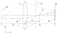
図1に本発明請求項1の立体像撮影装置の光学系の斜視図を示す。なお以下の各実施例はその光学系のみを表し、光学系を収納するケースや構造材は省略する。本実施例は対物レンズ(凸レンズ)1と、面上にシリンドリカルレンズが並んでなるレンチキュラーレンズ4と、撮像面5を持つ撮像手段と、水平スリット2を有する遮光板3からなる。ここでスリット2をx軸と平行に、xz面が水平面になるように直交座標をとると、レンチキュラーレンズ4はy軸と平行なシリンドリカルレンズがx方向に並んだものとなる。視野角の広い立体像を撮影するためには、対物レンズ1はその焦点距離に対してx方向の幅が広いものを使用するのが好ましい。このようなレンズは通常大型かつ肉厚で高価なものとなるが、フレネルレンズを使うことで安価にすることができる。撮像手段は感光フィルムや写真乾板あるいはCCDなどの撮像素子であり、感光フィルムや写真乾板では撮像面5は感光面を表す。感光フィルムや写真乾板を用いて撮影する場合にはさらに露光を制御する手段が必要があるが、これには遮光板3に近接して水平スリット2を開閉するシャッターを設けるか、レンチキュラーレンズ4の前面にフォーカルプレーンシャッターを設けるなどすればよい。
【0021】
図2にxz面の平面図を示し水平面内での機能を説明する。対物レンズ1の焦点距離をf1とし、対物レンズ1と撮像面5の距離をF2とするとき、対物レンズ1の前方に 1/f1=1/F1+1/F2 である距離F1だけ離れた位置に、対物レンズ1による撮像面5の像6が存在し、この位置がピント面となってその前後に存在する被写体の像が撮像面に投影される。この様子を図4の部分拡大図を使ってさらに説明する。撮像面5はレンチキュラーレンズ4から各シリンドリカルレンズの焦点距離にほぼ等しい距離だけ離れているため、撮像面5には各シリンドリカルレンズに入射する光線の角度分布に対応するものが、それぞれのシリンドリカルレンズに対応する像として形成される。厳密にはレンチキュラーレンズ4と撮像面5の距離がシリンドリカルレンズの焦点距離に等しいときに各投影像は入射する光線の角度分布となり、このとき最も焦点深度が深い立体像が得られる。逆にレンチキュラーレンズ4と撮像面5の距離をシリンドリカルレンズの焦点距離とは若干異なるものとすることにより、特定のピント面を有する立体像を得ることができる。ただこの距離をシリンドリカルレンズの焦点距離と大きく異なるものとすると焦点深度が浅くなりすぎて好ましくない。
【0022】
図3にyz面の平面図を示し鉛直面内での機能を説明する。xz面内と同様に対物レンズ1によって6の位置の像が撮像面5に投影されるが、レンチキュラーレンズ4はyz面内でレンズ機能を有さないため投影像は平面的な像となる。この際、遮光板3無しでは極めて焦点深度が浅い像となるが、立体像はある程度深い焦点深度がなければ平面像に対する優位性が無く、存在価値が無くなって好ましくない。このため水平スリット2を有する遮光板3で光線を絞り、焦点深度を稼ぐことが重要である。遮光板3は対物レンズ1から対物レンズ1の焦点距離f1より近い位置に置かれなければならず、このとき、対物レンズ1と遮光板3の距離をF3とすると、対物レンズ1から撮像面5のある側に 1/f1=1/F3−1/F4 である距離F4だけ離れた位置に、対物レンズ1による水平スリット2の像9が存在し、この位置が観測者の目の位置となって、近くにあるものが大きく、遠くのものが小さく見える平面像の遠近感が決定される。
【0023】
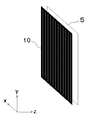
図1の立体像撮影装置において、レンチキュラーレンズ4はy軸に平行なスリットがx方向に並んだスリット板に置き換えることができる。図5はその様子を示したものである。スリット板10はy軸に平行なスリットが等間隔でx方向に並んだもので、これが図1のレンチキュラーレンズ4の代わりに撮像面5の前に置かれる。スリット板10と撮像面5は平行で、その間隔とスリット板10のスリットのピッチの比が、対物レンズ1とスリット板10の距離と対物レンズ1の幅の比に等しくすれば、撮像面5の全面を有効に使うことができる。またスリット板10と撮像面5の間隔を等しく保つためには、両者の間に透明な板を置き、スリット板10と撮像面5をその透明板に密着させて位置決めをする方法がある。この場合スリット板10は、該透明板の片面にスリット列を有する遮光パターンを印刷するなりして遮光層を形成したもので代用することができ、この場合は該遮光層がスリット板であると見なすことができる。
【0024】
レンチキュラーレンズ4を使った請求項1の立体像撮影装置では、シリンドリカルレンズの集束作用を使って入射光の角度分布に対する像を作るのに対し、スリット板10を用いる請求項2の立体像撮影装置においては、ピンホールレンズの原理によって同様の像を形成する。後者では焦点深度が深い像が得られる一方、像の解像度がスリットの幅で決まってしまうためスリット幅を十分狭くとる必要があり、このためレンチキュラーレンズ4を使う前者に比べて使える光の量が著しく少なくなるという問題がある。このため動きのある被写体のように露光時間を長くとれない場合には、レンチキュラーレンズ4を用いる請求項1の立体像撮影装置の方が適している。
【0025】
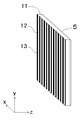
請求項1の立体像撮影装置において、より焦点深度の深い立体像を撮影するためには、図6に示すようなレンチキュラーレンズ11を用いる方法がある。レンチキュラーレンズ11は、シリンドリカルレンズ12と遮光部13が交互に並んだもので、シリンドリカルレンズ12の並ぶ間隔はレンチキュラーレンズ4と同じである。このように有効なシリンドリカルレンズの幅を減少する事で焦点深度は深くなり、レンズの収差も小さくできるので画質の向上も期待できる。一方使用する光量は減少するが、スリット板を使う時のような著しい減少ではないので、若干感度が低下する程度の副作用で済む。
【0026】
本立体像撮影装置によって撮影された立体像は、特願2002−112824に記載されている正の線描立体像にあたり、同明細書に示された立体像表示装置によって表示することができる。さらに特開2001−311909に記載の表示装置によっても表示することが可能である。
【0027】
該立体像を表示する装置の一例を図7に示す。本装置はライトボックス16と透明板15、立体像を記録した透過光制御手段14からなる。透明板15には片面に平行なスリット状の透過部を残して他の部分を遮光する遮光層17が形成され、透過光制御手段14は透明フィルム上に本発明の立体像表示装置で撮影した像が記録されたもの、あるいは同様の像を表示する液晶パネルなどである。これらは図7左に示したようにライトボックス16の発光面18の上に重ねて置かれるが、このとき撮影像の各シリンドリカルレンズないしスリットに対応する短冊状の各像に対し、遮光層17のスリットが1対1で対応する。
【0028】
本表示装置断面の拡大図を図8に示す。ライトボックスの光はスリットを通るものを除いて遮光層17に遮られ、スリットを通った光は透明板15を通って透過光制御手段14に至るが、透過光制御手段14には撮影の際に、シリンドリカルレンズないしスリットによって光線の角度分布が記録されており、これを通過した光によってこの角度分布が再現される。透明板15の遮光層17は、外光の反射によってコントラストが低下しないように黒色のインクで形成されるのが好ましいが、一方で遮光層17によって発光面18の光が吸収されてしまっては照明光の利用率が著しく低くなって好ましくない。そこで図8では、遮光層17の発光面18に面する側に反射層19を形成して照明光を反射し、反射光をさらに発光面18で反射して照明光に加えることで照明光の利用率を改善している。
【0029】
本発明を実施して立体像を楽しむ簡単な方法は、請求項1ないし請求項2の立体像撮影装置において、撮像手段にシート状のリバーサルフィルムを用いて撮影し、これを現像してポジ像のフィルムを得、これを図7の装置の透過光制御手段14に用いることである。このとき遮光層17のスリットの位置とピッチpは、光線の角度分布が正しく再生されるように決定されなければならない。具体的には図2において対物レンズ1に垂直に入射した光線8が、図8において表示面から垂直に出射する光線とならなければならない。撮影時、対物レンズ1によって光線8はいったん焦点7に集束され、図4に示すようにレンチキュラーレンズ4には垂直とは異なる角度で入射し、撮像面上ではシリンドリカルレンズの中心からdだけずれた位置に達する。このため表示装置における遮光層17のスリットピッチpは、撮影装置のレンチキュラーレンズ4ないしスリット板10のピッチより僅かに大きくしなければならない。
【0030】
dは容易に計算できるのでスリットピッチpを求めるのは難しくないが、もしレンチキュラーレンズ4のピッチとスリットピッチpが等しくできればなお簡便になり好ましい。請求項2の撮影装置を使って撮影する場合には、撮影時のスリット板のピッチと表示装置のスリットピッチpが等しければ、撮影装置に使ったスリット板と同じパターンが表示装置でも使えるためなおさら便利で好ましい。これを可能にしたのが請求項3および請求項4の立体像撮影装置である。
【0031】
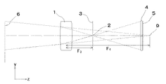
図9は図1の装置に第2の凸レンズ20を加えた請求項3の立体像撮影装置である。本装置において、対物レンズ1と第2の凸レンズ20の間隔は両レンズの焦点距離の和に等しい。図10に平面図を示すように、対物レンズ1に垂直に入射した光線は対物レンズ1の焦点距離f1だけ離れた焦点7に集束するが、焦点7は凸レンズ20からその焦点距離f2だけ離れており、凸レンズ20の焦点にもなっているから、凸レンズ20によってz軸に平行な光線、すなわちレンチキュラーレンズ4に垂直に入射する光線に変換される。本装置で撮影される立体像には図4のdに当たるずれが存在しない。これはレンチキュラーレンズ4の代わりにスリット板10を使用する請求項4の立体像撮影装置についても同様である。
【0032】
請求項3,4の立体像撮影装置においては、撮像面5へ投影倍率、すなわち撮影倍率は第2の凸レンズ20の焦点距離f2と対物レンズの焦点距離f1の比f2/f1となる。従ってf1とf2が等しい請求項5,6の立体像撮影装置は等倍像を撮影する撮影装置であるが、このような等倍撮影装置は、撮影像の表示装置を構成する際に特別な意味を持っている。
【0033】
図7,8の表示装置において透明板15の厚さは表示される立体像の遠近感に関係し、より厚くすれば遠近感が強調された立体像となり、逆に薄くすれば遠近感が抑えられた立体像となる。最もリアルな立体像を表示する厚さは、撮影装置における撮影倍率とレンチキュラーレンズ4の厚さ、ないしスリット板10と撮像面5の光学的距離などから計算することができるが、請求項5,6のように等倍撮影の場合には特に簡単で、レンチキュラーレンズ4のシリンドリカルレンズ面と撮像面5、ないしスリット板10と撮像面5の光学的距離が、図8における遮光層17と透過光制御手段14の光学的距離に等しくなるように透明板15の厚さを決めればよい。
【0034】
このことをさらに詳しく説明する。請求項5の立体像撮影装置において、撮像手段にシート状のリバーサルフィルムを用い、レンチキュラーレンズ4にフィルムを密着するように置いて撮影し、これを現像して図7,8の透過光制御手段14として使う場合には、透明板15はレンチキュラーレンズ4と屈折率が等しく厚さも等しいものを用い、遮光層17のスリットピッチpはレンチキュラーレンズ4のシリンドリカルレンズのピッチに等しくすればリアルな立体像が表示できる。
【0035】
請求項6の立体像撮影装置においては、同様に撮像手段にシート状のリバーサルフィルムを用い、スリット板10とフィルムの間に透明板をおいてスリット板10とフィルムを透明板に密着するように置いて撮影し、これを現像して図7,8の透過光制御手段14として使う場合には、透明板15は撮影時の透明板と屈折率が等しく厚さも等しいものを用い、遮光層17のスリットピッチpはスリット板10のスリットのピッチに等しくすればリアルな立体像が表示できる。
【0036】
さらに請求項6の立体像撮影装置において、請求項7の写真フィルムないし写真乾板を使うことで簡便に立体写真を楽しむことができる。請求項7の実施例を図11に示した。本写真乾板は図12に断面図を示すように、透明板21の片面に平行なスリット状の透過部を残して他の部分を遮光する遮光層22を有し、反対の面にポジ現像が可能な感光層23が形成されている。通常透明板21の厚さはスリットピッチと同程度であるので、スリットのピッチが小さくなれば厚さも薄くなりフィルム状の形態となる。
【0037】
本写真乾板ないし写真フィルムは請求項4ないし6のスリット板10と撮像面5を一体化したものであり、これらに置き換えて立体像を撮影することができる。さらに撮影後現像したものは図7の表示装置の透明板15と透過光制御手段14を一体化したものになっているため、そのままライトボックス16の上に置くだけで立体像を見ることができる。本写真乾板ないし写真フィルムは請求項6の等倍像を撮影する装置においてのみリアルな立体像の撮影、表示を可能にする。拡大倍率が1でない請求項4の装置に使えば、遠近感が実際より強調ないし弱められた立体像が表示されることになる。
【0038】
このように請求項7の写真フィルムないし写真乾板を使えば、遮光層17のスリットと透過光制御手段14上の記録像の位置合わせなどの煩雑な手続きを省くことができる。なお請求項7において図8の反射層19を設けて光線利用率を高めたい場合には、図13に断面図を示すように透明板21の遮光層22に重ねて反射層24を設け、その上に洗浄や薬品処理によって除去できる遮光層25を重ねて反射層24を覆った写真フィルムないし写真乾板を作り、撮影、現像後に遮光層25を除去すれば図8の反射層19に対応する反射層24を持った表示装置が構成できる。
【0039】
以上説明した立体像撮影装置は水平面内においてのみ立体感を有する立体像を撮影するものであるが、基本的に同様の構造を有する装置を使って上下の視差に対しても立体感を示す立体像を撮影することができる。このためには前述の立体像撮影装置において、レンチキュラーレンズ4ないしスリット板10を、面上に凸レンズないしピンホールが並んでなるレンズシートないしピンホール板に置き換え、水平スリット2を有する遮光板3を取り除けばよい。
【0040】
図15は請求項8の立体像撮影装置の光学系である。本実施例は対物レンズ(凸レンズ)30と、第2の凸レンズ31と、面上に凸レンズが並んでなるレンズシート32と、撮像面33を持つ撮像手段とからなり、対物レンズ30と第2の凸レンズ31の間隔は両レンズの焦点距離の和に等しい。本装置では図10に示した撮影原理がyz面内でも成り立ち、上下方向にも立体感を持った立体像が撮影できる。本装置はインテグラルフォトグラフィによる立体像撮影装置の一種と考えられるが、撮影倍率が第2の凸レンズ31の焦点距離と対物レンズ30の焦点距離の比で決まるという特徴を持っている。またレンズシート32はピンホール群が並んだピンホール板に置き換えることができる(請求項9)。
【0041】
本装置で撮影される立体像は特願2002−112824に記載されている正の点描立体像と互換性があり、同明細書に示された立体像表示装置によって表示することができる。また特開2001−311909に記載の表示装置によっても表示することができ、例えば図7の表示装置の遮光層17に形成されたスリット列をピンホール群に変えた装置で表示することができる。このとき図9の装置と同様の理由により、ピンホール群を並べる間隔は容易に決定することができ。さらに対物レンズ30と凸レンズ31の焦点距離が等しく、等倍像を撮影する請求項10,11の撮影装置においては、透明板15の厚さも簡単に決定できる。
【0042】
加えて請求項11の装置においては、請求項12のフィルムないし写真乾板を使って簡単に立体写真を撮影、表示することができる。請求項12の写真乾板は図11,12に示した請求項7の写真乾板のスリット状の透過部をピンホール状の透過部に変えたものであり、ピンホール板と撮像手段の機能を一体化したものである。本写真乾板を使い請求項11の撮影装置を用いて撮影した立体写真は、現像した後ライトボックスに載せるだけで立体像を見ることができる。
【0043】
本発明の請求項1〜6および請求項8〜11の立体像撮影装置は、単に立体像を撮影するだけでなく、使い方によってはさらに機能を加えた立体像を撮影することができる。図14は請求項6の立体像撮影装置を使った請求項13の撮影方法を示すもので、本実施例では対物レンズと第2の凸レンズにそれぞれフレネルレンズ26,27が使われており、スリット板と撮像手段には請求項7の写真乾板28が使われている。さらに対物レンズ26を覆うように置かれた遮蔽板29は開口部を持ち、x軸と平行に動かすことができる。
【0044】
本装置において、遮蔽板29を矢印の方向に移動しつつ動きのある被写体を撮影すれば、写真乾板28にはx軸方向の角度分布であると同時に時間変化でもある立体像が記録される。従って写真乾板28を現像してライトボックスに載せて見れば、見る角度によって被写体が変化するアニメーションのような効果を持った立体像が見えることになる。これは遮蔽板を連続的に動かした例であるが、水平スリット2の前後ないし写真乾板28の前などにシャッターを設け、遮蔽板29をその開口部が重ならないように数回動かしつつ、それぞれ全く異なる被写体を撮影すれば、見る角度によっていくつかの異なる被写体が切り替わって見える立体写真を撮ることも可能である。
【0045】
【発明の効果】
本発明の立体像撮影装置は、簡単な装置で立体像を撮影することができ、撮影した立体像は特殊な眼鏡やビュアーを使うことなく見ることができる。さらに本発明の立体写真撮影用フィルムないし乾板を使えば、特別な表示装置を必要とせずに立体像を見ることができる。さらに本発明の立体像撮影装置は、使用法を工夫することでアニメーション効果のような特殊な機能を持った立体写真を作成することもできる。
【図面の簡単な説明】
【図1】請求項1による立体像撮影装置の実施例である。
【図2】図1の実施例を上方から見た平面図である。
【図3】図1の実施例を側面から見た平面図である。
【図4】図1の実施例の撮影原理を説明する部分拡大図である。
【図5】本発明の請求項2,4,6に使われるスリット板の説明図である。
【図6】本発明の請求項1,3,5に使われるレンチキュラーレンズの一例を説明する図である。
【図7】本発明による撮影像を表示する立体像表示装置の一例である。
【図8】図7の表示装置の原理を説明する部分断面図である。
【図9】請求項3による立体像撮影装置の実施例である。
【図10】図9の実施例を上方から見た平面図である。
【図11】請求項7による立体写真撮影用フィルムないし乾板の実施例である。
【図12】図11のフィルムないし乾板の部分断面図である。
【図13】請求項7による立体写真撮影用フィルムないし乾板の他の実施例の部分断面図である。
【図14】請求項13による立体像撮影方法を実施する装置の例である。
【図15】請求項8による立体像撮影装置の実施例である。
【符号の説明】
1 ・・・ 対物レンズ(凸レンズ)
2 ・・・ 水平スリット
3 ・・・ 水平スリットを有する遮光板
4 ・・・ レンチキュラーレンズ
5 ・・・ 撮像面
6 ・・・ ピント面
7 ・・・ 対物レンズの焦点
8 ・・・ ピント面からz軸に平行に進む光線
9 ・・・ 対物レンズによる水平スリットの像
10 ・・・ スリット板
11 ・・・ シリンドリカルレンズの間に遮光部を有するレンチキュラーレンズ
12 ・・・ シリンドリカルレンズ
13 ・・・ 遮光部
14 ・・・ 撮影像を記録した透過光制御手段
15 ・・・ 透明板
16 ・・・ ライトボックス
17,22 ・・・ 平行に並んだスリット状の透過部を有する遮光層
18 ・・・ 発光面
19,24 ・・・ 反射層
20 ・・・ 第2の凸レンズ
21 ・・・ 透明板
23 ・・・ 感光層
25 ・・・ 洗浄や薬品処理によって除去できる遮光層
26 ・・・ 対物レンズ(フレネルレンズ)
27 ・・・ 第2の凸レンズ(フレネルレンズ)
28 ・・・ 請求項7の写真乾板
29 ・・・ 開口部を有する遮蔽板
30 ・・・ 対物レンズ(凸レンズ)
31 ・・・ 第2の凸レンズ
32 ・・・ レンズシート
33 ・・・ 撮像面[0001]
TECHNICAL FIELD OF THE INVENTION
The present invention relates to an apparatus for capturing a three-dimensional image.
[0002]
[Prior art]
Conventionally, in order to shoot and display a stereoscopic image, two images are taken with two cameras placed at a predetermined distance in the horizontal direction, and the two-dimensional images are taken using glasses using polarizing glass or color filters, or a special viewer. There are a method in which a photographed image can be seen by each of the right and left eyes, and a method in which a lenticular lens is used so as to be seen from different angles.
[0003]
In addition, as a method of shooting and displaying a stereoscopic image that can be viewed without using a special viewer, Integra Integrate uses a group of convex lenses arranged in a plane to take a picture of the subject and reproduces it using the same convex lens group Photography and holograms.
[0004]
[Problems to be solved by the invention]
Things that must be viewed using glasses or a viewer are extremely inconvenient to provide stereoscopic images to unspecified people. In addition, when multiple images are viewed from different angles using a lenticular lens, several images can be switched depending on the viewing angle, so depending on the viewing position, a double image may be seen or the observer may move. However, there is also a problem that an unnaturalness may be felt when viewing the image, and the angle range in which good observation can be performed is relatively narrow.
[0005]
In addition, integral photography has a problem that it is not easy to manufacture a photographing machine, and if it is used as it is, it becomes an unnatural three-dimensional image in which the perspective is reversed. It is difficult to enjoy.
[0006]
In order to solve these problems, the present inventor has devised a method of capturing and displaying a stereoscopic image different from the conventional method, and has already filed an application in Japanese Patent Application No. 2002-112824. Invented is a photographing device that can more easily photograph a three-dimensional image that can be displayed on the display device.
[0007]
[Means for Solving the Problems]
A first aspect of the present invention is directed to a lenticular lens in which an objective lens (convex lens), a cylindrical lens is arranged on a surface, and an imaging surface of the lenticular lens is parallel to the lenticular lens with an interval substantially equal to the focal length of the cylindrical lens. A light-shielding plate having a horizontal slit perpendicular to the axis of the cylindrical lens and positioned between the objective lens and the lenticular lens, between the objective lens and the lenticular lens, at a position closer to the focal length of the objective lens than the objective lens; Wherein the image of the subject is projected onto the imaging means through the objective lens, the horizontal slit, and the lenticular lens.
[0008]
Claim 2 of the present invention provides an objective lens (convex lens), a slit plate in which slits are arranged in parallel on a surface, an imaging means whose imaging surface is placed parallel to the slit plate, A light-shielding plate having a horizontal slit perpendicular to the slit of the slit plate, disposed between the lens and the slit plate at a position closer than the focal length of the objective lens from the objective lens, and the image of the subject is formed by the objective lens; A three-dimensional image photographing apparatus characterized by being projected onto the imaging means through the horizontal slit and the slit plate.
[0009]
Claim 3 of the present invention is an objective lens (convex lens), a second convex lens placed at a predetermined distance from the objective lens, and a cylindrical on the surface placed facing the second convex lens. A lenticular lens in which lenses are arranged, imaging means whose imaging surface is parallel to the lenticular lens, and spaced at a distance substantially equal to the focal length of the cylindrical lens; and a lens between the objective lens and the second convex lens. A light-shielding plate having a horizontal slit perpendicular to the axis of the cylindrical lens and located at a position closer to the focal length of the objective lens from the objective lens, and the distance between the objective lens and the second convex lens is set to Equal to the sum of the focal lengths, an image of the subject is projected onto the imaging means through the objective lens, the horizontal slit, the second convex lens and the lenticular lens. A three-dimensional image photographing apparatus according to claim Rukoto.
[0010]
Claim 4 of the present invention provides an objective lens (convex lens), a second convex lens placed at a predetermined distance from the objective lens, and a slit on the surface placed facing the second convex lens. Are arranged in parallel, imaging means whose imaging surface is placed in parallel with the slit plate, and a focal point of the objective lens from the objective lens between the objective lens and the second convex lens. A light-shielding plate having a horizontal slit perpendicular to the slit of the slit plate, and a distance between the objective lens and the second convex lens is equal to the sum of the focal lengths of both lenses; A three-dimensional image photographing apparatus wherein an image is projected onto the imaging means through the objective lens, the horizontal slit, the second convex lens, and the slit plate.
[0011]
A third aspect of the present invention is the stereoscopic image photographing apparatus according to the third aspect, wherein the objective lens (convex lens) and the second convex lens have the same focal length.
[0012]
A sixth aspect of the present invention is the stereoscopic image photographing apparatus according to the fourth aspect, wherein the objective lens (convex lens) and the second convex lens have the same focal length.
[0013]
According to a seventh aspect of the present invention, there is provided a photographic film or a dry plate which is convenient for taking a three-dimensional photograph by using the apparatus according to the sixth aspect, except that a transparent plate or a slit-shaped transparent portion parallel to one surface of the film is left. A three-dimensional photographic film or a dry plate in which a light-shielding layer for shielding light from light is formed and a photosensitive layer capable of positive development is formed on the other surface.
[0014]
Claim 8 of the present invention relates to an objective lens (convex lens), a second convex lens placed at a predetermined distance from the objective lens, and a convex lens on the surface placed facing the second convex lens. And an imaging means whose imaging surface is parallel to the lens sheet and is spaced at an interval substantially equal to the focal length of the convex lens of the lens sheet. The objective lens and the second convex lens The distance is equal to the sum of the focal lengths of the two lenses, and the image of the subject is projected onto the imaging means through the objective lens, the second convex lens, and the lens sheet, and is a three-dimensional image photographing apparatus.
[0015]
According to a ninth aspect of the present invention, there is provided an objective lens (convex lens), a second convex lens disposed at a predetermined distance from the objective lens, and a pin disposed on the surface facing the second convex lens. It consists of a pinhole plate in which holes are arranged, and imaging means whose imaging surface is placed parallel to the pinhole plate, and the distance between the objective lens and the second convex lens is equal to the sum of the focal lengths of both lenses. A three-dimensional image photographing apparatus wherein an image of a subject is projected onto the imaging means through the objective lens, the second convex lens, and the pinhole plate.
[0016]
A tenth aspect of the present invention is the stereoscopic image photographing apparatus according to the eighth aspect, wherein the objective lens (convex lens) and the second convex lens have the same focal length.
[0017]
An eleventh aspect of the present invention is the stereoscopic image photographing apparatus according to the ninth aspect, wherein the objective lens (convex lens) and the second convex lens have the same focal length.
[0018]
According to a twelfth aspect of the present invention, there is provided a photographic film or a dry plate which is convenient for taking a three-dimensional photograph by the apparatus according to the eleventh aspect, wherein a transparent plate or a pinhole-shaped transmission plate arranged at a predetermined interval on one surface of the film. A three-dimensional photographic film or a dry plate in which a light-shielding layer for shielding other portions except for a portion is formed, and a photosensitive layer capable of positive development is formed on another surface.
[0019]
According to a thirteenth aspect of the present invention, in the three-dimensional image photographing apparatus according to the first to sixth aspects and the eighth to eleventh aspects, a shielding plate that blocks part of the objective lens while leaving the other part close to the objective lens is provided. A three-dimensional image photographing method characterized by photographing a three-dimensional image accompanied by a change in the subject depending on the viewing angle by changing the subject while photographing while moving the opening of the shielding plate.
[0020]
BEST MODE FOR CARRYING OUT THE INVENTION
FIG. 1 is a perspective view of an optical system of the three-dimensional image photographing apparatus of the present invention. In the following embodiments, only the optical system is shown, and a case and a structural material for housing the optical system are omitted. The present embodiment includes an objective lens (convex lens) 1, a lenticular lens 4 having cylindrical lenses arranged on a surface, an imaging unit having an imaging surface 5, and a light shielding plate 3 having a horizontal slit 2. Here, when the rectangular coordinates are set so that the slit 2 is parallel to the x-axis and the xz plane is a horizontal plane, the lenticular lens 4 is a cylindrical lens parallel to the y-axis arranged in the x-direction. In order to capture a stereoscopic image with a wide viewing angle, it is preferable to use the objective lens 1 having a wide width in the x direction with respect to the focal length. Such lenses are usually large, thick and expensive, but can be made inexpensive by using Fresnel lenses. The image pickup means is an image pickup device such as a photosensitive film, a photographic plate or a CCD. In the case of a photosensitive film or a photographic plate, the image pickup surface 5 represents a photosensitive surface. When taking a picture using a photosensitive film or a photographic dry plate, a means for further controlling the exposure is necessary. For this purpose, a shutter for opening and closing the horizontal slit 2 close to the light shielding plate 3 is provided, or a lenticular lens 4 is provided. For example, a focal plane shutter may be provided on the front.
[0021]
FIG. 2 is a plan view of the xz plane, and functions in a horizontal plane will be described. Assuming that the focal length of the objective lens 1 is f1 and the distance between the objective lens 1 and the imaging surface 5 is F2, a position 1 / f1 = 1 / F1 + 1 / F2 in front of the objective lens 1 is separated by a distance F1. An image 6 of the imaging surface 5 by the objective lens 1 exists, and this position serves as a focus surface, and images of a subject existing before and after the image are projected onto the imaging surface. This situation will be further described with reference to a partially enlarged view of FIG. Since the imaging surface 5 is separated from the lenticular lens 4 by a distance substantially equal to the focal length of each cylindrical lens, the imaging surface 5 corresponds to the angular distribution of light rays incident on each of the cylindrical lenses, Formed as the corresponding image. Strictly speaking, when the distance between the lenticular lens 4 and the imaging surface 5 is equal to the focal length of the cylindrical lens, each projected image has an angular distribution of incident light rays, and at this time, a three-dimensional image with the deepest focal depth is obtained. Conversely, by setting the distance between the lenticular lens 4 and the imaging surface 5 slightly different from the focal length of the cylindrical lens, a stereoscopic image having a specific focus surface can be obtained. However, if this distance is greatly different from the focal length of the cylindrical lens, the depth of focus is undesirably too small.
[0022]
FIG. 3 is a plan view of the yz plane, and functions in a vertical plane will be described. The image at the position 6 is projected onto the imaging surface 5 by the objective lens 1 as in the xz plane, but the lenticular lens 4 has no lens function in the yz plane, so that the projected image is a planar image. At this time, an image having an extremely shallow depth of focus is obtained without the light-shielding plate 3, but a three-dimensional image has no superiority to a planar image unless it has a certain depth of focus, and is not preferable because it has no value. For this reason, it is important to stop the light beam with the light shielding plate 3 having the horizontal slit 2 to increase the depth of focus. The light shielding plate 3 must be placed at a position closer to the focal length f1 of the objective lens 1 from the objective lens 1. At this time, if the distance between the objective lens 1 and the light shielding plate 3 is F3, An image 9 of the horizontal slit 2 by the objective lens 1 exists at a position at a distance F4 of 1 / f1 = 1 / F3-1 / F4 on the side where there is, and this position is the position of the eyes of the observer. Thus, the perspective of a planar image in which a nearby object is large and a distant object is small is determined.
[0023]
In the three-dimensional image photographing apparatus of FIG. 1, the lenticular lens 4 can be replaced by a slit plate in which slits parallel to the y-axis are arranged in the x direction. FIG. 5 shows this state. The slit plate 10 has slits parallel to the y-axis arranged at equal intervals in the x direction, and is placed in front of the imaging surface 5 instead of the lenticular lens 4 in FIG. The slit plate 10 and the imaging surface 5 are parallel. If the distance between the slit and the slit pitch of the slit plate 10 is equal to the ratio of the distance between the objective lens 1 and the slit plate 10 and the width of the objective lens 1, the imaging surface 5 Can be used effectively. In order to keep the distance between the slit plate 10 and the imaging surface 5 equal, there is a method in which a transparent plate is placed between the two, and the slit plate 10 and the imaging surface 5 are closely attached to the transparent plate for positioning. In this case, the slit plate 10 can be replaced with a light shielding pattern formed by printing a light shielding pattern having a slit row on one surface of the transparent plate. In this case, the light shielding layer is a slit plate. Can be considered.
[0024]
In the three-dimensional image photographing apparatus according to the first aspect using the lenticular lens, an image corresponding to the angular distribution of the incident light is formed using the focusing action of the cylindrical lens, whereas the three-dimensional image photographing apparatus according to the second aspect uses the slit plate. , A similar image is formed by the principle of a pinhole lens. In the latter case, an image with a large depth of focus can be obtained. On the other hand, the resolution of the image is determined by the width of the slit. Therefore, it is necessary to make the slit width sufficiently narrow. Therefore, the amount of light that can be used is smaller than that of the former using the lenticular lens 4. There is a problem that it is significantly reduced. Therefore, when the exposure time cannot be long as in the case of a moving subject, the three-dimensional image photographing apparatus using the lenticular lens 4 is more suitable.
[0025]
In the three-dimensional image photographing apparatus of the first aspect, there is a method of using a lenticular lens 11 as shown in FIG. 6 to photograph a three-dimensional image with a deeper depth of focus. The lenticular lens 11 has cylindrical lenses 12 and light shielding portions 13 alternately arranged. The intervals at which the cylindrical lenses 12 are arranged are the same as those of the lenticular lens 4. By reducing the width of the effective cylindrical lens in this way, the depth of focus is increased and the aberration of the lens can be reduced, so that an improvement in image quality can be expected. On the other hand, although the amount of light used is reduced, it is not a remarkable decrease as when a slit plate is used.
[0026]
The three-dimensional image captured by the three-dimensional image capturing apparatus corresponds to a positive line drawing three-dimensional image described in Japanese Patent Application No. 2002-112824, and can be displayed by the three-dimensional image display apparatus described in the same specification. Further, the image can be displayed by the display device described in JP-A-2001-311909.
[0027]
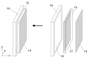
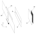
FIG. 7 shows an example of a device for displaying the stereoscopic image. This apparatus comprises a light box 16, a transparent plate 15, and transmitted light control means 14 for recording a three-dimensional image. The transparent plate 15 is provided with a light-shielding layer 17 that shields the other part while leaving a slit-shaped transmission part parallel to one surface, and the transmitted light control means 14 is photographed on the transparent film by the stereoscopic image display device of the present invention. A liquid crystal panel on which an image is recorded or a similar image is displayed. These are placed on the light emitting surface 18 of the light box 16 as shown on the left side of FIG. 7, and at this time, the light shielding layer 17 is applied to each of the rectangular images corresponding to the cylindrical lenses or slits of the photographed image. Correspond one-to-one.
[0028]
FIG. 8 is an enlarged view of a cross section of the present display device. The light of the light box is blocked by the light shielding layer 17 except for the one that passes through the slit, and the light that has passed through the slit passes through the transparent plate 15 and reaches the transmitted light control means 14. The angular distribution of the light beam is recorded by a cylindrical lens or a slit, and the angular distribution is reproduced by the light passing therethrough. The light-shielding layer 17 of the transparent plate 15 is preferably formed of black ink so that the contrast is not reduced by the reflection of external light, but on the other hand, if the light of the light-emitting surface 18 is absorbed by the light-shielding layer 17. The utilization rate of the illumination light is extremely low, which is not preferable. In FIG. 8, a reflection layer 19 is formed on the light-shielding layer 17 on the side facing the light-emitting surface 18 to reflect the illumination light, and the reflected light is further reflected by the light-emitting surface 18 and added to the illumination light, thereby obtaining the illumination light. Utilization is improving.
[0029]
A simple method of enjoying a three-dimensional image by implementing the present invention is to provide a three-dimensional image photographing apparatus according to any one of claims 1 and 2, wherein a photograph is taken using a sheet-like reversal film as an image pickup means, and the photographed image is developed to obtain a positive image. Is used for the transmitted light control means 14 of the apparatus shown in FIG. At this time, the position of the slit and the pitch p of the light shielding layer 17 must be determined so that the angular distribution of the light beam is reproduced correctly. Specifically, the light beam 8 that is vertically incident on the objective lens 1 in FIG. 2 must be a light beam that exits vertically from the display surface in FIG. At the time of photographing, the light beam 8 is once focused on the focal point 7 by the objective lens 1 and is incident on the lenticular lens 4 at an angle different from the vertical as shown in FIG. 4, and is shifted by d from the center of the cylindrical lens on the imaging surface. Reach position. For this reason, the slit pitch p of the light-shielding layer 17 in the display device must be slightly larger than the pitch of the lenticular lens 4 or the slit plate 10 of the photographing device.
[0030]
Since d can be easily calculated, it is not difficult to find the slit pitch p. However, if the pitch of the lenticular lens 4 and the slit pitch p can be made equal, it is more convenient and preferable. In the case of photographing using the photographing device of claim 2, if the pitch of the slit plate at the time of photographing is equal to the slit pitch p of the display device, the same pattern as the slit plate used in the photographing device can be used in the display device, and furthermore, Convenient and preferred. The three-dimensional image photographing apparatus according to the third and fourth aspects makes this possible.
[0031]
FIG. 9 shows a three-dimensional image photographing apparatus according to claim 3, in which a second convex lens 20 is added to the apparatus shown in FIG. In this apparatus, the distance between the objective lens 1 and the second convex lens 20 is equal to the sum of the focal lengths of both lenses. As shown in the plan view of FIG. 10, the light beam perpendicularly incident on the objective lens 1 is focused on a focal point 7 which is separated by a focal length f1 of the objective lens 1, but the focal point 7 is separated from the convex lens 20 by a focal length f2 thereof. Since it is also the focal point of the convex lens 20, it is converted by the convex lens 20 into a light beam parallel to the z-axis, that is, a light beam that is perpendicularly incident on the lenticular lens 4. There is no shift corresponding to d in FIG. 4 in the stereoscopic image photographed by the present apparatus. The same applies to the stereoscopic image photographing apparatus according to claim 4 in which the slit plate 10 is used instead of the lenticular lens 4.
[0032]
In the three-dimensional image photographing apparatus of the third and fourth aspects, the projection magnification to the imaging surface 5, that is, the photographing magnification is a ratio f2 / f1 of the focal length f2 of the second convex lens 20 and the focal length f1 of the objective lens. Therefore, the three-dimensional image photographing apparatus according to claims 5 and 6 in which f1 and f2 are equal to each other is a photographing apparatus for photographing a 1: 1 image, but such a 1: 1 image photographing apparatus is special when constructing a photographed image display device. Have meaning.
[0033]
In the display device of FIGS. 7 and 8, the thickness of the transparent plate 15 is related to the perspective of the displayed stereoscopic image, and when the thickness is larger, the perspective is enhanced, and when the thickness is thinner, the perspective is suppressed. 3D image. The thickness for displaying the most realistic three-dimensional image can be calculated from the photographing magnification in the photographing apparatus and the thickness of the lenticular lens 4 or the optical distance between the slit plate 10 and the image pickup surface 5. In particular, in the case of the same-magnification photographing as shown in FIG. 6, the optical distance between the cylindrical lens surface of the lenticular lens 4 and the imaging surface 5 or the optical distance between the slit plate 10 and the imaging surface 5 differs from the light shielding layer 17 and the transmitted light in FIG. The thickness of the transparent plate 15 may be determined so as to be equal to the optical distance of the control means 14.
[0034]
This will be described in more detail. 7. A three-dimensional image photographing apparatus according to claim 5, wherein a sheet-like reversal film is used as an image pickup means, a film is placed so as to be in close contact with the lenticular lens 4, and the film is developed and transmitted light control means shown in FIGS. When used as 14, a transparent plate 15 having the same refractive index and the same thickness as the lenticular lens 4 is used, and the slit pitch p of the light shielding layer 17 is made equal to the pitch of the cylindrical lens of the lenticular lens 4, so that a real stereoscopic image can be obtained. Can be displayed.
[0035]
In the three-dimensional image photographing apparatus according to the sixth aspect, similarly, a sheet-like reversal film is used for the imaging means, and a transparent plate is provided between the slit plate 10 and the film so that the slit plate 10 and the film are in close contact with the transparent plate. 7 and 8, and used as the transmitted light control means 14 in FIGS. 7 and 8, the transparent plate 15 has the same refractive index and the same thickness as the transparent plate at the time of photographing. If the slit pitch p is equal to the slit pitch of the slit plate 10, a real three-dimensional image can be displayed.
[0036]
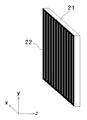
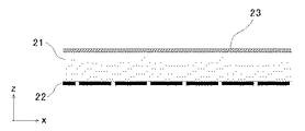
Further, in the three-dimensional image photographing apparatus of the sixth aspect, the three-dimensional photograph can be easily enjoyed by using the photographic film or the photographic dry plate of the seventh aspect. An embodiment according to claim 7 is shown in FIG. As shown in the cross-sectional view of FIG. 12, this photographic dry plate has a light-shielding layer 22 that shields the other portion while leaving a slit-shaped transparent portion parallel to one surface of a transparent plate 21, and performs positive development on the opposite surface. A possible photosensitive layer 23 is formed. Normally, the thickness of the transparent plate 21 is substantially the same as the slit pitch. Therefore, when the pitch of the slits is reduced, the thickness is reduced and the film is formed.
[0037]
The present photographic dry plate or photographic film is obtained by integrating the slit plate 10 and the imaging surface 5 according to claims 4 to 6, and can take a three-dimensional image by replacing them. Further, after the photographing and development, the transparent plate 15 and the transmitted light control means 14 of the display device of FIG. 7 are integrated, so that a stereoscopic image can be viewed simply by placing it on the light box 16 as it is. . The present photographic dry plate or photographic film enables real stereoscopic images to be photographed and displayed only in the apparatus for photographing the same-magnification image according to claim 6. If the enlargement magnification is not 1, the stereoscopic image in which the perspective is emphasized or weakened more than the actual one is displayed.
[0038]
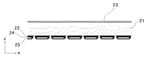
By using the photographic film or photographic dry plate according to the seventh aspect, complicated procedures such as alignment of the slit of the light shielding layer 17 and the recorded image on the transmitted light control means 14 can be omitted. In the case where it is desired to increase the light utilization rate by providing the reflection layer 19 of FIG. 8 in claim 7, a reflection layer 24 is provided so as to overlap the light shielding layer 22 of the transparent plate 21 as shown in the sectional view of FIG. A light-shielding layer 25 that can be removed by washing or chemical treatment is superposed thereon to produce a photographic film or a photographic dry plate that covers the reflection layer 24. After the photographing and development, the light-shielding layer 25 is removed, and the reflection corresponding to the reflection layer 19 in FIG. A display device having the layer 24 can be formed.
[0039]
Although the above-described three-dimensional image capturing apparatus captures a three-dimensional image having a three-dimensional effect only in a horizontal plane, a three-dimensional image that exhibits a three-dimensional effect even in the upper and lower parallax using a device having a basically similar structure. Images can be taken. For this purpose, in the above-mentioned stereoscopic image photographing apparatus, the lenticular lens 4 or the slit plate 10 is replaced with a lens sheet or a pinhole plate in which convex lenses or pinholes are arranged on the surface, and the light-shielding plate 3 having the horizontal slit 2 is replaced. Just remove it.
[0040]
FIG. 15 shows an optical system of the three-dimensional image photographing apparatus according to claim 8. This embodiment includes an objective lens (convex lens) 30, a second convex lens 31, a lens sheet 32 in which convex lenses are arranged on a surface, and imaging means having an imaging surface 33. The interval between the convex lenses 31 is equal to the sum of the focal lengths of both lenses. In this device, the imaging principle shown in FIG. 10 is also valid in the yz plane, and a three-dimensional image having a three-dimensional effect can be taken in the vertical direction. This apparatus is considered to be a kind of three-dimensional image photographing apparatus using integral photography, and has a feature that the photographing magnification is determined by the ratio of the focal length of the second convex lens 31 to the focal length of the objective lens 30. Further, the lens sheet 32 can be replaced with a pinhole plate in which pinhole groups are arranged (claim 9).
[0041]
The stereoscopic image photographed by the present apparatus is compatible with the positive stippling stereoscopic image described in Japanese Patent Application No. 2002-112824, and can be displayed by the stereoscopic image display device described in the same specification. The display can also be performed by the display device described in JP-A-2001-311909. For example, the display can be performed by a device in which the slit array formed in the light shielding layer 17 of the display device in FIG. At this time, the interval at which the pinhole groups are arranged can be easily determined for the same reason as in the apparatus of FIG. Further, in the photographing apparatuses according to the tenth and eleventh aspects, in which the objective lens 30 and the convex lens 31 have the same focal length and photograph an equal-magnification image, the thickness of the transparent plate 15 can be easily determined.
[0042]
In addition, in the apparatus according to the eleventh aspect, it is possible to easily take and display a stereoscopic photograph using the film or the photographic dry plate according to the twelfth aspect. The photographic dry plate according to the twelfth aspect is obtained by changing the slit-shaped transmission portion of the photographic dry plate according to the seventh aspect shown in FIGS. 11 and 12 into a pinhole-shaped transmission portion, and integrally functions the pinhole plate and the imaging means. It is a thing. A three-dimensional photograph taken using the photographic dry plate and using the photographing device according to claim 11 can be viewed as a three-dimensional image simply by developing and placing it on a light box.
[0043]
The three-dimensional image photographing apparatuses according to the first to sixth and eighth to eleventh aspects of the present invention can not only photograph a three-dimensional image but also photograph a three-dimensional image with additional functions depending on how to use it. FIG. 14 shows a photographing method according to claim 13 using the three-dimensional image photographing apparatus according to claim 6. In this embodiment, Fresnel lenses 26 and 27 are used for an objective lens and a second convex lens, respectively, and a slit is used. The photographic dry plate 28 of claim 7 is used for the plate and the imaging means. Further, the shielding plate 29 placed so as to cover the objective lens 26 has an opening and can be moved in parallel with the x-axis.
[0044]
In the present apparatus, if a moving subject is photographed while moving the shielding plate 29 in the direction of the arrow, a three-dimensional image that has an angular distribution in the x-axis direction and also changes with time is recorded on the photographic dry plate 28. Therefore, if the photographic plate 28 is developed and placed on a light box and viewed, a three-dimensional image having an effect such as an animation in which the subject changes depending on the viewing angle will be seen. This is an example in which the shielding plate is continuously moved, but a shutter is provided before and after the horizontal slit 2 or in front of the photographic dry plate 28, and the shielding plate 29 is rotated several times so that the openings do not overlap, and If a completely different subject is photographed, it is also possible to take a three-dimensional photograph in which several different subjects are switched depending on the viewing angle.
[0045]
【The invention's effect】
The three-dimensional image photographing apparatus of the present invention can photograph a three-dimensional image with a simple device, and the photographed three-dimensional image can be viewed without using special glasses or a viewer. Further, the use of the film or the dry plate for stereo photography of the present invention enables a stereoscopic image to be viewed without the need for a special display device. Further, the stereoscopic image photographing apparatus of the present invention can create a stereoscopic photograph having a special function such as an animation effect by devising the usage.
[Brief description of the drawings]
FIG. 1 is an embodiment of a three-dimensional image photographing apparatus according to claim 1;
FIG. 2 is a plan view of the embodiment of FIG. 1 as viewed from above.
FIG. 3 is a plan view of the embodiment of FIG. 1 as viewed from the side.
FIG. 4 is a partially enlarged view for explaining a photographing principle of the embodiment of FIG. 1;
FIG. 5 is an explanatory view of a slit plate used in claims 2, 4, and 6 of the present invention.
FIG. 6 is a diagram illustrating an example of a lenticular lens used in claims 1, 3, and 5 of the present invention.
FIG. 7 is an example of a stereoscopic image display device for displaying a captured image according to the present invention.
8 is a partial cross-sectional view illustrating the principle of the display device of FIG.
FIG. 9 is an embodiment of a three-dimensional image photographing apparatus according to claim 3;
10 is a plan view of the embodiment of FIG. 9 as viewed from above.
FIG. 11 is an embodiment of a film or a dry plate for stereoscopic photography according to claim 7;
FIG. 12 is a partial sectional view of the film or the drying plate of FIG. 11;
FIG. 13 is a partial sectional view of another embodiment of a film or a dry plate for stereophotography according to claim 7;
FIG. 14 is an example of an apparatus for implementing the stereoscopic image photographing method according to claim 13;
FIG. 15 is an embodiment of a stereoscopic image photographing apparatus according to claim 8;
[Explanation of symbols]
1 ... Objective lens (convex lens)
2 ... horizontal slit
3... Light shield having horizontal slits
4 ··· Lenticular lens
5 ... imaging surface
6: Focus surface
7 Focus of objective lens
8 Light rays traveling parallel to the z-axis from the focus plane
9 ... image of horizontal slit by objective lens
10 ・ ・ ・ slit plate
11 ··· Lenticular lens having a light blocking portion between cylindrical lenses
12 ··· Cylindrical lens
13 ... light-shielding part
14... Transmitted light control means that records a captured image
15 ... transparent plate
16 Light box
17, 22 ... light-shielding layer having slit-shaped transmission portions arranged in parallel
18 Light-emitting surface
19, 24 ... reflective layer
20... Second convex lens
21 ・ ・ ・ transparent plate
23 ... photosensitive layer
25 ... light-shielding layer that can be removed by washing or chemical treatment
26 ... Objective lens (Fresnel lens)
27 ... second convex lens (Fresnel lens)
28 ··· The photographic plate of claim 7
29 ··· Shielding plate with opening
30 ... objective lens (convex lens)
31... Second convex lens
32 ・ ・ ・ Lens sheet
33 ・ ・ ・ Imaging surface