JP2004237987A - Package - Google Patents

Package Download PDF

Info

Publication number
JP2004237987A
JP2004237987A JP2003025960A JP2003025960A JP2004237987A JP 2004237987 A JP2004237987 A JP 2004237987A JP 2003025960 A JP2003025960 A JP 2003025960A JP 2003025960 A JP2003025960 A JP 2003025960A JP 2004237987 A JP2004237987 A JP 2004237987A
Authority
JP
Japan
Prior art keywords
article
package
storage space
stored
main body
Prior art date
Legal status (The legal status is an assumption and is not a legal conclusion. Google has not performed a legal analysis and makes no representation as to the accuracy of the status listed.)
Pending
Application number
JP2003025960A
Other languages
Japanese (ja)
Inventor
Kosuke Otaki
滝 浩 右 大
Masao Totsu
津 政 夫 遠
Current Assignee (The listed assignees may be inaccurate. Google has not performed a legal analysis and makes no representation or warranty as to the accuracy of the list.)
MAINTECH KANZAI KK
Mentec Kanzai Co Ltd
SP Chemical KK
Original Assignee
MAINTECH KANZAI KK
Mentec Kanzai Co Ltd
SP Chemical KK
Priority date (The priority date is an assumption and is not a legal conclusion. Google has not performed a legal analysis and makes no representation as to the accuracy of the date listed.)
Filing date
Publication date
Application filed by MAINTECH KANZAI KK, Mentec Kanzai Co Ltd, SP Chemical KK filed Critical MAINTECH KANZAI KK
Priority to JP2003025960A priority Critical patent/JP2004237987A/en
Publication of JP2004237987A publication Critical patent/JP2004237987A/en
Pending legal-status Critical Current

Links

Images

Abstract

<P>PROBLEM TO BE SOLVED: To well package a large volume article, a fresh fruit for example. <P>SOLUTION: This package 10 for buffering a shock to a stored article 1 (melon M) by air pressure includes a body 11 formed to be tubular with the air enclosable in a bag portion 15 to form a storage space 16 capable of receiving the article inside, a stopper 12 provided inside at the lower end of the body with the air enclosable in the bag portion 15 to be capable of coming into contact with the article stored in the storage space, and a flap 13 provided at the upper end of the body for preventing the article stored in the space from coming out. <P>COPYRIGHT: (C)2004,JPO&NCIPI

Description

【0001】
【発明の属する技術分野】
本発明は包装体に係り、特にメロンなどのように物流における取り扱いが比較的困難な、体積の大きな物品を包装するに好適な包装体に関する。
【0002】
【従来の技術】
体積の大きな物品、例えばメロンなどの生鮮果実は、特許文献1に記載の如く、発泡スチロールネットで個装したうえ、段ボール箱などの単位包装体内で、木毛などの緩衝材を用いて包装されている。
また、販売店の店頭において、上記メロンなどは、上記段ボール箱から取り出されて発泡スチロールネットに包装された状態で陳列されたり、段ボール箱に包装された状態で陳列されている。
【0003】
【特許文献1】
特開平10‐287369号公報(第2頁)
【0004】
【発明が解決しようとする課題】
ところが、メロンなどの陳列に際し発泡スチロールネットにて包装された状態では、このネットが、落下の衝撃や、メロンどうしの衝突による衝撃などに対し十分な緩衝効果を発揮し得ず、良好な包装がなされているとは言えない。
また、段ボール箱に収納された状態でメロンを陳列したのでは、メロンを目視できないため、陳列効果が低下してしまう。
【0005】
本発明の目的は、上述の事情を考慮してなされたものであり、体積の大きな物品、例えば生鮮果実を良好に包装できる包装体を提供することにある。
【0006】
【課題を解決するための手段】
請求項1に記載の発明は、収納した物品に対する衝撃を、気体の圧力により緩衝する包装体であって、筒形状に形成されて気体が封入可能とされ、内側に上記物品を収納可能な収納空間を形成する本体部と、この本体部の一端側における内側に配設されると共に、気体が封入可能とされ、上記収納空間内に収納された上記物品に当接可能なストッパ部と、を有することを特徴とするものである。
【0007】
請求項2に記載の発明は、請求項1に記載の発明において、上記本体部の他端側には、収納空間内に収納された物品の飛び出し防止用のフラップ部が配設されたことを特徴とするものである。
【0008】
請求項3に記載の発明は、請求項1に記載の発明において、上記本体部の他端側における内側には、気体が封入可能とされ、収納空間内に収納された物品に当接して当該物品の飛び出しを防止する抑止部が配設されたことを特徴とするものである。
【0009】
請求項4に記載の発明は、請求項1乃至3のいずれかに記載の発明において、上記本体の他端側に、把持可能な取っ手部が設けられたことを特徴とするものである。
【0010】
請求項5に記載の発明は、収納した物品に対する衝撃を、気体の圧力により緩衝する包装体であって、筒形状に形成されて気体が封入可能とされ、内側に上記物品を収納可能な収納空間が形成されると共に、一端側が漸次縮径して縮径部とされ、この縮径部が、上記収納空間内に収納された上記物品に当接可能に構成されたことを特徴とするものである。
【0011】
請求項6に記載の発明は、請求項5に記載の発明において、上記一端側へ延びる切込みが他端側に形成され、この切込みにより分割された上記他端側部分が接合されて、収納空間内に収納された物品の飛び出しが防止可能に構成されたことを特徴とするものである。
【0012】
請求項7に記載の発明は、請求項5または6に記載の発明において、上記他端側に、把持可能な取っ手部が設けられたことを特徴とするものである。
【0013】
【発明の実施の形態】
以下、本発明の実施の形態を、図面に基づき説明する。
[A]第1の実施の形態(図1〜図8;請求項1,2及び5に対応)
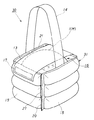
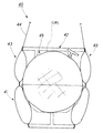
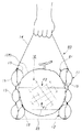
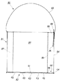
図1は、本発明に係る包装体の第1の実施の形態を示す斜視図である。図5は、図1の包装体で、空気を封入する前の斜視図である。
【0014】
これらの図1及び図5に示す包装体10は、収納した物品1に対する外方からの衝撃を、気体としての空気の圧力により緩衝するものであって、本体部11、ストッパ部12、フラップ部13及び取っ手部14を有して構成される。これらの本体部11、ストッパ部12、フラップ部13及び取っ手部14は、柔軟な気密性の高い合成樹脂フィルムにて構成されている。
ここで、上記物品1は体積の大きな物品であり、例えばメロンM(図7)やスイカなどの生鮮果実、あるいは植木鉢U(図8)などである。
【0015】
上記本体部11は、図1、図5〜図7に示すように、空気を封入可能な多数の袋部15を備えて六角筒形状に形成される。この本体部11の内側には、上記袋部15に空気が封入されてこの袋部15が膨出された状態においても、物品1が収納可能な収納空間16が形成される。
【0016】
前記ストッパ部12は、本体部11の一端側(本実施の形態では下端側)における内側に配設され、空気を封入可能な複数の上記袋部15を備えて構成される。このストッパ部12は、当該ストッパ部12を構成する袋部15に空気が封入されたときに膨出して、本体部11の下端側における内側の開口面積を縮小する。従って、ストッパ部12を構成する袋部15に空気が封入されたときに、このストッパ部12は、収納空間16内に収納された物品1に当接してストッパ機能を果たし、この物品1が本体部11の下端から抜け落ちることを防止すると共に、この物品1を包装体10の下端から持ち上げて保持する。
【0017】
前記フラップ部13はシート形状に形成され、本体部11の他端側(本実施の形態では上端側)に配設される。このフラップ部13は、基端部が本体部11の上記上端に熱接合され、先端部に接着テープ17が装着されている。フラップ部13は、本体部11の収納空間16内に物品1が収納されたときに、この物品1を覆う位置に設けられて、物品1が収納空間16内から飛び出すことを防止する。尚、このフラップ部13の幅は、六角形をなす本体部11の上端縁形状の一辺の長さよりも狭く形成されている。
【0018】
前記取っ手部14はシート形状に形成され、本体部11の他端側(本実施の形態では上端側)に配設される。この取っ手部14は、物品1を覆うフラップ部13に対して交差するように、その両端が本体部11の上端に熱接合される。この取っ手部14を把持することによって、包装体10が持ち運び可能とされる。尚、この取っ手部14は、フラップ部13よりも狭い幅に形成されている。
【0019】
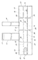
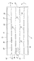
ところで、上記本体部11及び上記ストッパ部12は、図2〜図5に示す手順によって製作される。つまり、図2に示すように、長方形状又は正方形状の表面シート18と、この表面シート18と同形状の裏面シート19とを用意する。これらの表面シート18と裏面シート19のそれぞれの外周縁部をヒートシールなどにより熱接合して、図2の縦、横に縦外縁接合部20、横外縁接合部21をそれぞれ形成し、これら(縦外縁接合部20、横外縁接合部21)と平行してヒートシールなどにより表面シート18及び裏面シート19を熱接合して、それぞれ複数の縦接合部22及び横接合部23を形成する。
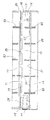
次に、このように熱接合された表面シート18及び裏面シート19を、一方の横外縁接合部21に最も近い横接合部23上の仮想直線25を境として例えば表面シート18側に折り重ね、図3に示すように、ヒートシールなどにより熱接合して複数の縦接合部24を形成する。これらの縦接合部24のそれぞれは、縦接合部22の各々と同一直線状に設けられ、本実施の形態では、表面シート18及び裏面シート19の長手方向に沿って等間隔に5列設けられる。
【0020】
その後、図4に示すように、表面シート18を内側に、裏面シート19を外側に位置付けるようにして屈曲または湾曲させ、両端に位置する縦外縁接合部20をヒートシールなどにより熱接合する。このとき、図5に示すように、熱接合された表面シート18及び裏面シート19の大部分は、同一直線状にある縦接合部22及び24を境に折り曲げられて、六角形状の本体部11を構成する。更に、仮想直線25を境に表面シート18側に折り曲げられた表面シート18及び裏面シート19の一部は、本体部11の下端側に配設されたストッパ部12を構成し、このストッパ部12も縦接合部24を境に折り曲げられる。
【0021】
ここで、図2及び図3に示すように、表面シート18及び裏面シート19には、縦外縁接合部20、横外縁接合部21、縦接合部22、24及び横接合部23により囲まれて多数の袋部15が形成され、本体部11及びストッパ部12は、これらの袋部15が連接されて構成される。また、縦外縁接合部20及び横外縁接合部21が連続して形成されているのに対し、縦接合部22及び24と横接合部23とのそれぞれは連続せず、所定の隙間を隔てて形成されている。このため、本体部11及びストッパ部12を構成する多数の袋部15は、縦接合部22、24及び横接合部23の上記隙間により形成された通気部26によって連通されることになる。従って、本体部11とストッパ部12とは、袋部15への空気の封入に関し上記通気部26を用いて連通される。
【0022】
図5に示すように、本体部11には給排気口27が設けられる。この給排気口27は、本体部11における一つの袋部15内に逆止弁28(図3)を備える。この逆止弁28によって、本体部11の袋部15内に封入された空気が外部へ流出しないよう構成される。また、給排気口27から逆止弁28を経て空気が供給されることにより、本体部11及びストッパ部12の全ての袋部15に、通気部26を経て空気が封入される。
【0023】
このように、本体部11及びストッパ部12の袋部15に空気が封入されることによって、図7及び図8に示すように、これら本体部11及びストッパ部12の袋部15が収納空間16内に膨出し、本体部11の袋部15は収納空間16内の物品1を空気圧により保持し、ストッパ部12の袋部15は、本体部11の下端側の開口面積を縮小して、収納空間16内の物品1が本体部11の下端側から抜け落ちることを防止する。更に、収納空間16内の物品1は、本体部11及びストッパ部12のそれぞれにおける袋部15内の空気の圧力によって、包装体10外の衝撃に対し緩衝される。
【0024】
上述のように構成された包装体10では、本体部11の給排気口27から本体部11及びストッパ部12の袋部15内へ空気を供給した後に、本体部11の収納空間16内に物品1を収納してもよく、或いは、本体部11及びストッパ部12の袋部15内へ空気を供給する前に本体部11の収納空間16内に物品1を収納し、その後、給排気口27を介して、本体部11及びストッパ部12の袋部15内へ空気を供給して封入してもよい。後者の場合には、収納空間16内の物品1が、本体部11及びストッパ部12の袋部15内における空気の圧力により挟持されて、収納空間16内に保持されることになる。
【0025】
以上のように構成されたことから、上記実施の形態によれば、次の効果(1)〜(5)を奏する。
(1)六角形状に形成されて袋部15に空気が封入可能とされた本体部11の内側に、袋部15内に空気が封入された状態で物品1を収納可能な収納空間16が形成され、また、本体部11の下端側における内側に配設されて袋部15に空気が封入可能とされたストッパ部12が、この袋部15に空気が封入された状態で、収納空間16内に収納された物品1に当接することから、このストッパ部12により、物品1が収納空間16内から抜け落ちることを防止でき、物品1を収納空間16内に良好に保持して包装することができる。
【0026】
(2)本体部11及びストッパ部12は、空気が封入可能な多数の袋部15により構成されるので、これらの袋部15に空気が封入されることによって、本体部11の収納空間16内に収納された物品1に対し、包装体10の外部からの衝撃を袋部15内の空気の圧力により吸収することで、この衝撃を良好に緩衝することができる。
【0027】
(3)包装体10では、フラップ部13が本体部11の上端側に配設されて、本体部11の収納空間16内に収納された物品1の飛び出しを防止する機能を果たすことから、このフラップ部13によって、物品1を包装体10内に、より一層良好に保持することができる。
【0028】
(4)包装体10では、本体部11、ストッパ部12及びフラップ部13が透明フィルムにて形成された場合には、収納空間16内に収納された物品1を外部から目視できるので、包装体10の収納空間16内にメロンMなどの物品1を収納した状態で、この包装体10を店頭の陳列棚または陳列台上に載置することによって、陳列効果を高めることができる。
【0029】
(5)包装体10では、取っ手部14が本体部11の上端側に固着されたことから、この取っ手部14を把持することによって、例えば陳列棚または陳列台上に載置され、物品1としてのメロンMを収納した包装体10をレジカウンタまで移動させることができ、また、購入後に持ち運びでき、更に、購入者の家屋内においてメロンMの熟成のために、取っ手部14を用いて包装体10を懸吊し、この状態で物品1(メロンM)を保管することができる。
【0030】
[B]第2の実施の形態(図9及び図10;請求項1,2及び5に対応)
図9は、本発明に係る包装体の第2の実施の形態を示す斜視図である。この第2の実施の形態において、前記第1の実施の形態と同様な部分は、同一の符号を付すことにより説明を省略する。
【0031】
この第2の実施の形態の包装体30は、本体部31が四角形状に構成されたものである。従って、この本体部31を形成する表面シート18及び裏面シート19には、同一直線状に設けられた縦接合部22及び24が、表面シート18及び裏面シート19の長手方向に沿って等間隔に3列形成される。表面シート18及び裏面シート19の上端部における縦外縁接合部20を、ヒートシールなどにより熱接合して本体部31を形成する際に、三箇所の上記縦接合部22及び24が折り曲げられて、本体部31は四角筒形状に構成される。
この包装体30においても、前記第1の実施の形態の包装体10の効果(1)〜(5)と同様な効果を奏する。
【0032】
[C]第3の実施の形態(図11〜図16;請求項7,8及び11に対応)
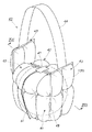
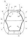
図11は、本発明に係る包装体の第3の実施の形態を示す斜視図である。図12は、図11におけるフラップ部が接合されて閉じられる前の状態を示す斜視図である。この第3の実施の形態において、前記第1の実施の形態と同様な部分は、同一の符号を付すことにより説明を省略する。
【0033】
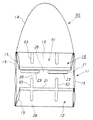
これらの図11及び図12に示す包装体40は、収納した物品1に対する外方からの衝撃を、気体としての空気の圧力により緩衝するものであり、縮径部41、フラップ部42、取っ手基部43及び取っ手部44を有して構成される。これらの縮径部41、フラップ部42、取っ手基部43及び取っ手部44は、柔軟な気密性の高い合成樹脂フィルムにて構成されている。
【0034】
フラップ部42が互いに接合されていない状態で、縮径部41、フラップ部42及び取っ手基部43は、図12に示すように筒形状に形成される。また、これらの縮径部41、フラップ部42及び取っ手基部43は、空気を封入可能な多数の袋部15が連接されて構成される。そして、これらの縮径部41、フラップ部42及び取っ手基部43に囲まれて、物品1を収納可能な収納空間45が形成される。
【0035】
上記縮径部41は、図15及び図16に示すように、包装体40の一端側(本実施の形態では下端側)に設けられ、一端側先端(本実施の形態では下方先端)へ向かって漸次縮径して構成される。従って、縮径部41を構成する袋部15に空気が封入されたとき、この縮径部41は、収納空間45内に収納された物品1に当接して、この物品1が包装体40の下端から抜け落ちることを防止すると共に、この物品1を包装体40の下端から持ち上げて保持する。
【0036】
図12に示すように、包装体40の他端側(本実施の形態では上端側)には、下端へ向かって延びる切込み46が、所定間隔で複数本(例えば4本)設けられる。包装体40の上端側は、これら複数本の切込み46により分割されてフラップ部42及び取っ手基部43として構成される。このうち、取っ手基部43は、対向した位置に一対配置される。
【0037】
上記フラップ部42は、収納空間45内に物品1が収納された状態で、図11に示すようにそれらの上端部が、例えば接着テープ47等によって接合されて当該物品1を覆う。これにより、物品1が包装体40から飛び出すことが防止される。また、上記取っ手基部43のそれぞれに、前記取っ手部44の端部が熱接合される。この取っ手部44を把持することによって、包装体40が持ち運び可能とされる。
【0038】
ところで、この包装体40においても、縮径部41、フラップ部42及び取っ手基部43は、表面シート18及び裏面シート19を重ね合わせて、ヒートシールなどにより熱接合することにより構成される。つまり、図13に示すように、重ね合わされた表面シート18及び裏面シート19にヒートシールなどにより縦外縁接合部20及び横外縁接合部21を形成し、更に、横外縁接合部21に平行して、表面シート18及び裏面シート19の中央位置に複数の横接合部49をヒートシールなどの熱接合により、所定の隙間を隔てて一列に形成する。と同時に、縦外縁接合部20に平行して、複数の縦接合部48をヒートシールなどの熱接合によって複数列形成する。これらの縦接合部48は、各列において、所定の隙間を隔てて複数個形成される。
【0039】
次に、熱接合により重ね合わされた表面シート18及び裏面シート19に複数本の切込み46を形成する。この切込み46は、重ね合わされた表面シート18及び裏面シート19の長手方向中央位置で、この長手方向に直交して設けられた仮想直線50に対し対称した位置に形成される。更に、この切込み46は縦接合部46に形成される。
【0040】
次に、重ね合わされた表面シート18及び裏面シート19を、上記仮想直線50を境に折り曲げて重ね合わせ、図14(A)に示すように、表面シート18及び裏面シート19の両端に位置する縦外縁接合部20どうしをヒートシールなどにより熱接合して、筒形状の包装体40の原型体53を構成する。
【0041】
その後、この筒形状の原型体53において、横接合部49よりも図14(B)における下方側部分の左右両端部を、ヒートシールなどにより斜めに熱接合して傾斜接合部51を形成する。この状態で、原型体53における傾斜接合部51の外側の三角形状部分52を切断して除去し、包装体40を構成する。
【0042】
上述のようにして、図14(B)における包装体40の横接合部49を境とした下半部分に、下端へ向かい漸次縮径した形状の縮径部41が形成される。また、図14(B)における包装体40の横接合部49を境とした上半部分には、複数本の切込み46により分割されて、フラップ部42及び取っ手基部43が形成される。
【0043】
尚、縮径部41、フラップ部42及び取っ手基部43には、図13に示すように、縦外縁接合部20、横外縁接合部21、縦接合部48、横接合部49及び傾斜接合部51に囲まれて、多数の袋部15が形成される。更に、この包装体40においても、縦接合部48及び横接合部49が互いに隙間を隔てて設けられているので、この隙間により通気部26が形成されて、縮径部41、フラップ部42及び取っ手基部43を構成する多数の袋部15は、上記通気部26により連通される。従って、図14(B)に示すように、給排気口27が縮径部41に設けられるが、この給排気口27から空気が供給されることで、縮径部41、フラップ部42及び取っ手基部43の全ての袋部15内へ空気が供給されて、これらの袋部15が膨出する。
【0044】
上述のように構成された包装体40では、縮径部41の給排気口27から縮径部41、フラップ部42及び取っ手基部43の袋部15内へ空気を供給した後に、収納空間45内に物品1を収納してもよく、または、縮径部41、フラップ部42及び取っ手基部43の袋部15内へ空気を供給する前に収納空間45内に物品1を収納し、その後、給排気口27を介して縮径部41、フラップ部42及び取っ手基部43の袋部15内に空気を供給して封入してもよい。後者の場合には、収納空間45内の物品1が、縮径部41、フラップ部42及び取っ手基部43の袋部15内における空気の圧力により挟持されて、収納空間45内に保持されることになる。
【0045】
以上のように構成されたことから、この実施の形態の包装体40によれば、次の効果(6)〜(10)を奏する。
(6)縮径部41、フラップ部42及び取っ手基部43は筒形状に形成されて、これらを構成する多数の袋部15に空気が封入可能とされ、上記縮径部41、フラップ部42及び取っ手基部43に囲まれて収納空間45が形成され、上記縮径部41が、その袋部15に空気が封入された状態で、収納空間45内に収納された物品1に当接することから、この縮径部41により、物品1が収納空間45内から抜け落ちることを防止でき、物品1を収納空間45内に良好に保持して包装することができる。
【0046】
(7)縮径部41、フラップ部42及び取っ手基部43は、空気が封入可能な多数の袋部15により構成されるので、これらの縮径部41、フラップ部42及び取っ手基部43の袋部15に空気が封入されることによって、収納空間45内に収納された物品1に対し、包装体40の外部からの衝撃を袋部15内の空気の圧力により吸収することで、この衝撃を良好に緩衝することができる。
【0047】
(8)包装体40では、フラップ部42が接着テープ47等により接合されて、収納空間45内に収納された物品1の飛び出しを防止する機能を果たすことから、このフラップ部42によって、物品1を包装体40内に、より一層良好に保持することができる。
【0048】
(9)包装体40では、縮径部41、フラップ部42及び取っ手基部43が透明フィルムにて構成された場合には、収納空間45内に収納された物品1を外部から目視できるので、包装体40の収納空間45内にメロンMなどの物品1を収納した状態で、この包装体40を店頭の陳列棚または陳列台上に載置することによって、陳列効果を高めることができる。
【0049】
(10)包装体40では、取っ手部44が取っ手基部43に固着されたことから、この取っ手部44を把持することによって、例えば陳列棚または陳列台上に載置され、物品1としてのメロンMを収納した包装体40をレジカウンタまで移動させることができ、また、購入後に持ち運ぶことができ、更に、購入者の家屋内においてメロンMの熟成のために、取っ手部44を用いて包装体40を懸吊し、この状態で物品1(メロンM)を保管することができる。
【0050】
[D]第4の実施の形態(図17〜図22;請求項1、3及び5に対応)
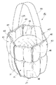
図17は、本発明に係る包装体の第4の実施の形態を示す斜視図である。図22は、図17のXXII‐XXII線に沿う断面図である。この第4の実施の形態において、前記第1の実施の形態と同様な部分は、同一の符号を付すことにより説明を省略する。
【0051】
これらの図17及び図22に示す包装体60は、図1及び図7に示す包装体10において、フラップ部13を抑止部61に変更したものであり、収納空間16内に収納されたメロンMなどの物品1は、この抑止部61によりその飛び出しが抑止される。
【0052】
つまり、包装体60の本体部11は六角筒形状に形成されて、その内側に収納空間16が形成される。そして、この本体部11には、その一端側(本実施の形態では下端側)の内側にストッパ部12が一体に配設されると共に、その他端側(本実施の形態では上端側)の内側に上記抑止部61が一体に配設される。ストッパ部12及び抑止部61は、気体としての空気を封入可能な多数の袋部15を有してなり、これらの袋部15に空気が封入されたときに収納空間16側へ膨出可能とされる。
【0053】
ストッパ部12は、収納空間16側へ膨出されることによって、この収納空間16内に収納された物品1に当接してこの物品1を押圧し、物品1が収納空間16の下方から抜け落ちることを防止すると共に、この物品1を包装体60の下端から持ち上げて保持する。また、上記抑止部61は、収納空間16側へ膨出されることによって、この収納空間16内に収納された物品1に当接してこの物品1を押圧し、物品1が収納空間16の上方へ飛び出すことを防止する。
【0054】
この抑止部61を備えた包装体60の製造手順を、図18〜図20を用いて説明する。
図18に示すように、表面シート18及び裏面シート19に縦外縁接合部20、横外縁接合部21及び横接合部23を、ヒートシールなどの熱接合によって形成する。次に、このように熱接合された表面シート18及び裏面シート19を、一方の横外縁接合部21に最も近い横接合部23上の仮想直線25を境として、例えば表面シート18側に折り重ねる共に、他方の横外縁接合部21に最も近い横接合部23付近の仮想直線62を境として、同様に表面シート18側に折り重ねる。
【0055】
この状態で、図19に示すように、重ね合わされた表面シート18及び裏面シート19に、縦外縁接合部20に平行して縦接合部63を、ヒートシールなどの熱接合により形成する。この縦接合部63は、表面シート18及び裏面シート19の長手方向に沿ってほぼ等間隔に5列設けられる。
【0056】
その後、図20に示すように、表面シート18を内側に、裏面シート19を外側にそれぞれ位置付けて屈曲させ、両端に位置する縦外縁接合部20をヒートシールなどにより熱接合する。更に、本体部11の上端縁に取っ手部14の両端を、同様にして熱接合する。
【0057】
上述のように、熱接合された表面シート18及び裏面シート19の大部分は、縦接合部63を境に屈曲されて、六角形状の本体部11を構成する。また、仮想直線25を境に折り曲げられた表面シート18及び裏面シート19の一部は、縦接合部63を境に屈曲されて、本体部11の下端部に配設されるストッパ部12を構成する。更に、仮想直線62を境に折り曲げられた表面シート18及び裏面シート19の一部は、縦接合部63を境に屈曲されて、本体部11の上端部に配設される抑止部61を構成する。
【0058】
このように構成された本体部11、ストッパ部12及び抑止部61は、図21に示すように、多数の袋部15が連接されて構成される。この袋部15は、図19に示すように、表面シート18及び裏面シート19において、縦外縁接合部20、横外縁接合部21、縦接合部63及び横接合部23に囲まれて形成されたものである。
【0059】
この袋部15に空気を供給する前に(図20)、本体部11の収納空間16内にメロンMなどの物品1を収納させ、その後、給排気口27から本体部11、ストッパ部12及び抑止部61を構成する全ての袋部15へ空気を封入することによって、図22に示すように、本体部11、ストッパ部12及び抑止部61の袋部15が収納空間16側へ膨出する。この膨出したストッパ部12の袋部15によって物品1の抜け落ちが防止されるとともに、物品1に抑止部61側へ向かう力F1が作用し、また、膨出した抑止部61の袋部15によって物品1の飛び出しが防止されるとともに、物品1にストッパ部12側へ向かう力F2が作用する。そして、上記力F1及びF2により物品1が挟持されて収納空間16内に保持される。
【0060】
以上のように構成されたことから、上記実施の形態によっても、前記第1の実施の形態の包装体10の効果(1)、(2)および(5)と同様な効果を奏する他、次の効果(11)、(12)および(13)を奏する。
(11)抑止部61は本体部11の上端側に配設され、この抑止部61の袋部15に封入された空気の圧力により、本体部11の収納空間16内に収納された物品1に当接してこの物品1を押圧することから、物品1が本体部11から飛び出すことを確実に防止または抑止できる。
【0061】
(12)本体部11の収納空間16内に収納された物品1には、空気により膨出されたストッパ部12により上向きの力F1が作用し、また、空気により膨出された抑止部61により下向きの力F2が作用するので、上記物品1は、これらの力F1及びF2により挟持されて、収納空間16内により一層良好に保持される。と同時に、本体部11及びストッパ部12の袋部15内の空気圧のみならず、抑止部61の袋部15内の空気圧によっても、物品1に作用する衝撃を良好に緩衝できる。
【0062】
(13)包装体60では、本体部11、ストッパ部12及び抑止部61が透明フィルムにて形成された場合には、収納空間16内に収納された物品1を外部から目視できるので、包装体60の収納空間16内にメロンMなどの物品1を収納した状態で、この包装体60を店頭の陳列棚または陳列台上に載置することによって、陳列効果を高めることができる。
【0063】
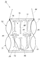
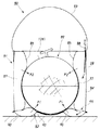
(E)第5の実施の形態(図23〜図28;請求項9、10及び11に対応)図23は、本発明に係る包装体の第5の実施の形態を示す斜視図である。図27は、図23のXXVII‐XXVII線に沿う断面図である。この第5の実施の形態において、前記第1及び第3の実施の形態と同様な部分は、同一の符号を付すことにより説明を省略する。
【0064】
これらの図23及び図27に示す包装体70は、収納した物品1に対する外方からの衝撃を、気体としての空気の圧力により緩衝するものであり、一端側部としての下半部71、他端側部としての上半部72、位置決め手段としての位置決めフラップ73、及び取っ手部44を有して構成される。これらの下半部71、上半部72、位置決めフラップ73及び取っ手部44は、柔軟な気密性の高い合成樹脂フィルムにて構成されている。
【0065】
下半部71及び上半部72は、図25に示すように筒形状に形成され、空気が封入可能な多数の袋部15が連接されて構成される。そして、これらの下半部71及び上半部72に囲まれて、物品1を収納可能な収納空間75が形成される。
【0066】
図26及び図27に示すように、上記下半部71は、包装体70の一端側(本実施の形態では下端側)に設けられ、上記上半部72は、包装体70の他端側(本実施の形態では上端側)に設けられる。これらの下半部71と上半部72の境界が、後述の横接合部49である。
【0067】
収納空間75内に物品1が収納されない状態で、上記下半部71及び上半部72を構成する袋部15に空気が封入されたときには、図28に示すように、下半部71及び上半部72は、横接合部49を境として内側に折れ曲がることなく、直線状に維持される。
【0068】
ところが、図26に示すように、収納空間75内に物品1(この図26ではメロンMを収納するカップ33)が収納され、しかも、この物品1の最大外径部分1A(この図26ではカップ33の最大外径部分1A)が横接合部49に対応して位置付けられた状態で、下半部71及び上半部72を構成する袋部15内に空気が封入された場合には、図27に示すように、横接合部49は物品1の最大外径部分1Aによって位置規制されるため包装体70の内側へ移動できず、下半部71及び上半部72の袋部15が内側へ膨出して物品1に当接又は接触し、この物品1を押圧する。これにより、下半部71及び上半部72は横接合部49を境として内側に折れ曲がり、下半部71は、一端側先端(本実施の形態では下方先端)へ向かって漸次縮径された形状となって、物品1(及びカップ33)に斜め上向きの力K1を作用する。また、上半部72は、他端側先端(本実施の形態では上方先端)へ向かって漸次縮径された形状となって、物品1(及びカップ33)に斜め下向きの力K2を作用する。
【0069】
従って、下半部71を構成する袋部15に空気が封入されたとき、この下半部71は、収納空間75内に収納された物品1に当接して、この物品1が包装体70の下端から抜け落ちることを防止すると共に、物品1を包装体70の下端から持ち上げる。また、上半部72を構成する袋部15に空気が封入されたとき、この上半部72は、収納空間75内に収納された物品1に当接して、この物品1が包装体70の上端から飛び出すことを防止する。
【0070】
前記位置決めフラップ部73は、図25及び図28に示すように、それらの上端部76が上半部72の上端縁に接着され、収納空間75内に垂れ下げられた状態で配設される。収納空間75内に収納される物品1は、図27に示すように、この位置決めフラップ73に係止されて、包装体70から抜け落ちることが防止される。しかも、この位置決めフラップ73の長さは、図26に示すように、下半部71及び上半部72を構成する袋部15内に空気が封入されない状態で物品1を係止したとき、この物品1の最大外径部分1Aを下半部71と上半部72との境界に相当する横接合部49に位置付けるべく調整されて設定される。この状態では、物品1の重量で包装体70の下半部71が縮み変形し、位置決めフラップ73に係止された物品1は、包装体70が載置された机や床などに支持される。
【0071】
前記取っ手部44は、上半部72の上端縁、例えば位置決めフラップ73と同一の位置に接着される。この取っ手部44を把持することによって、包装体70が持ち運び可能とされる。
【0072】
ところで、この包装体70においても、下半部71及び上半部72は、図24に示すように、表面シート18及び裏面シート19を重ね合わせて、ヒートシールなどにより熱接合することにより構成される。つまり、重ね合わされた表面シート18及び裏面シート19にヒートシールなどにより縦外縁接合部20及び横外縁接合部21を形成し、更に、横外縁接合部21に平行して、表面シート18及び裏面シート19の中央位置に複数の横接合部49をヒートシールなどの熱接合により、所定の隙間を隔てて一列に形成する。と同時に、縦外縁接合部20に平行して、複数の縦接合部48をヒートシールなどの熱接合によって複数列形成する。これらの縦接合部48は、各列において、所定の隙間を隔てて複数個形成される。
【0073】
次に、重ね合わされた表面シート18及び裏面シート19を、これらの表面シート18及び裏面シート19の長手方向中央位置で、この長手方向に直交して設けられた仮想直線50を境に折り曲げて重ね合わせる。そして、図25に示すように、表面シート18及び裏面シート19の両端に位置する縦外縁接合部20どうしをヒートシールなどにより熱接合して、筒形状の包装体70を構成する。このようにして、包装体70の横接合部49を境とした下半部分に下半部71が、上半部分に上半部72がそれぞれ形成される。
【0074】
尚、下半部71及び上半部72には、図24に示すように、縦外縁接合部20、横外縁接合部21、縦接合部48及び横接合部49に囲まれて、多数の袋部15が形成される。更に、この包装体70においても、縦接合部48及び横接合部49が互いに隙間を隔てて設けられているので、この隙間により通気部26が形成されて、下半部71及び上半部72を構成する多数の袋部15は、上記通気部26により互いに連通される。従って、図25に示すように、給排気口27が上半部72に設けられるが、この給排気口27から空気が供給されることで、下半部71及び上半部72の全ての袋部15内へ空気が供給されて、これらの袋部15が膨出する。
【0075】
上述のように構成された包装体70では、下半部71及び上半部72の袋部15内へ空気を供給する前に収納空間75内に物品1を収納し、その後、給排気口27を介して、下半部71及び上半部72の袋部15内に空気を供給して封入する。この場合には、収納空間75内の物品1は、下半部71及び上半部72の袋部15内における空気の圧力により力K1及びK2が作用されて挟持され、収納空間75内に保持されることになる。
【0076】
以上のように構成されたことから、この実施の形態の包装体70によれば、次の効果(11)〜(16)を奏する。
(11)下半部71及び上半部72は筒形状に形成されて、これらを構成する多数の袋部15に空気が封入可能とされ、上記下半部71及び上半部72に囲まれて収納空間75が形成され、上記下半部71が、その袋部15に空気が封入された状態で、収納空間75内に収納された物品1に当接することから、この下半部71により、物品1が収納空間75内から抜け落ちることを防止でき、物品1を収納空間75内に良好に保持して包装することができる。
【0077】
(12)下半部71及び上半部72は、空気が封入可能な多数の袋部15により構成されるので、これらの下半部71及び上半部72の袋部15に空気が封入されることによって、この袋部15内の空気の圧力が、収納空間75内に収納された物品1に対し、包装体70の外部からの衝撃を吸収でき、この衝撃を良好に緩衝することができる。
【0078】
(13)包装体70では、上半部72を構成する袋体15に空気が封入されることにより、この上半部72が内側に膨出して物品1に当接することから、収納空間75内に収納された物品1の飛び出しを防止できるので、物品1を包装体70内に、より一層良好に保持することができる。
【0079】
(14)包装体70では、下半部71、上半部72及び位置決めフラップ73が透明フィルムにて構成された場合には、収納空間75内に収納された物品1を外部から目視できるので、包装体70の収納空間75内にメロンMなどの物品1を収納した状態で、この包装体70を店頭の陳列棚または陳列台上に載置することによって、陳列効果を高めることができる。
【0080】
(15)包装体70では、取っ手部44が上半部72の上端縁に固着されたことから、この取っ手部44を把持することによって、例えば陳列棚または陳列台上に載置され、物品1としてのメロンMを収納した包装体70をレジカウンタまで移動させることができ、また、購入後に持ち運ぶことができ、更に、購入者の家屋内においてメロンMの熟成のために、取っ手部44を用いて包装体70を懸吊し、この状態で物品1(メロンM)を保管することができる。
(16)位置決めフラップ73が収納空間75内に収納された物品1を係止することから、下半部71及び上半部72を構成する袋部15から万一空気が抜けてしまった場合にも、この位置決めフラップ73によって、包装体70からの物品1の抜け落ちを確実に防止できる。
【0081】
[F]第6の実施の形態(図29〜図33;請求項4、5及び6に対応)
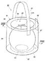
図29は、本発明に係る包装体の第6の実施の形態を示す斜視図である。図33は、図29のXXXIII‐XXXIII線に沿う断面図である。この第6の実施の形態において、前記第1の実施の形態と同様な部分は、同一の符号を付すことにより説明を省略する。
【0082】
これらの図29及び図33に示す包装体80は、収納した物品1に対する外方からの衝撃を、気体としての空気の圧力により緩衝するものであり、本体部81、閉塞部としての底部82、及び取っ手部83を有して構成される。これらの本体部81、底部82及び取っ手部83は気密性の高い、特に柔軟な合成樹脂フィルム(例えばオレフィン系素材)にて構成される。
【0083】
上記本体部81は、図31及び図32に示すように、外周面84の内側に内周面85が同心円状に配置され、これらの外周面84及び内周面85の上縁が、リング形状の天面86により熱接合されて閉塞され、外周面84及び内周面85の下縁が後述の如く底部82に熱接合されて閉塞されて、円筒形状に構成される。
【0084】
これらの外周面84、内周面85、天面86及び底部82に囲まれた空間87内に空気が封入可能とされる。この空気は、天面86と外周面84又は内周面85との境界部分に配設された給排気口88を通して空間87内へ供給される。また、上記内周面85の内側に、物品1を収納可能な収納空間89が形成される。
【0085】
前記底部82は、本体部81の一端側(本実施の形態では下端側)に熱接合されて、この本体部81における空間87及び収納空間89の下方を閉塞する。これにより、底部82は、収納空間89内に収納された物品1に当接して、この物品1が包装体80の下部から抜け落ちることを防止する。
【0086】
この底部82は、図30に示すように、円板形状のアッパシート91とロアシート92とが同心円状に配置され、それらの中央部分がリング状に熱接合され(このリング状接合部を図31及び図32に符号93で示す。)、これらアッパシート91及びロアシート92の外周縁が本体部81における外周面84の下端縁94に熱接合されて構成される。また、本体部81における内周面85の下端縁95は、底部82のアッパシート91に熱接合される。
【0087】
上記底部82は、図32に示すように、アッパシート91及びロアシート92に囲まれて、リング状接合部93の外側に膨出部90を備える。この膨出部90は、図33に示すように、空気が封入されて膨出可能とされ、底部82の外周に沿ってドーナツ形状に設けられる。この膨出部90は、膨出状態では、包装体80が机や床などに載置されたとき、これらの机や床などに直接に接触して、この包装体80の安定性を確保する。更に、膨出状態の膨出部90は、収納空間89内に収納された物品1を包装体80の下端から持ち上げて、物品1が机や床などに直接接触しないように保持する。
【0088】
上記底部82のアッパシート91には、図32及び図33に示すように、本体部81の空間87に対応する位置に通気穴96が形成される。従って、給排気口88から空間87内に供給された空気は、上記通気穴96を経て膨出部90内へ供給され、この膨出部90を膨出させる。また、図31に示すように、本体部81の外周面84に前記取っ手部83が熱接合される。この取っ手部83を把持することにより、包装体80の持ち運びが可能とされる。
【0089】
上述のように構成された包装体80では、本体部81の空間87及び底部82の膨出部90へ空気を供給する前に、本体部81の収納空間89内に物品1を収納する。その後、給排気口88を用いて、本体部81の空間87及び底部82の膨出部90内へ空気を封入する。すると、図33に示すように、底部82の膨出部90が収納空間89内の物品1を机や床などから持ち上げると共に、本体部81の内周面85が内側へ膨出する。この内周面85は、内側に膨出する間に、収納空間89内に収納された物品1の外表面に接触し、この物品1の形状に沿って変形する。特に、内周面85の上方部分は、収納空間89内の物品1に斜め下向きの力P2を作用し、底部82の膨出部90が、収納空間89内の物品1に作用する斜め上向きの力P1との相乗作用で、物品1を挟持する。
【0090】
以上のように構成されたことから、上記実施の形態によれば、次の効果(17)〜(22)を奏する。
(17)円筒形状に形成されて空間87に空気が封入可能とされた本体部81の内側に、物品1を収納可能な収納空間89が形成され、また、本体部81の下端側を閉塞する底部82が、収納空間89内に収納された物品1に当接することから、この底部82により物品1が収納空間89から抜け落ちることを防止でき、物品1を収納空間89内に良好に保持して包装することができる。
【0091】
(18)本体部81の空間87及び底部82の膨出部90に空気が封入されることから、これらの空気の圧力が、本体部81の収納空間89内に収納された物品1に対し、包装体80の外部からの衝撃を吸収でき、この衝撃を良好に緩衝することができる。
【0092】
(19)本体部81の空間87及び底部82の膨出部90に空気が封入されることにより、本体部81の収納空間89内に収納された物品1に対し、本体部81の内周面85が力P2を作用し、底部82の膨出部90が力P1を作用することから、これらの力P1及びP2によって、収納空間89内の物品1を挟持でき、その飛び出しを防止できる。
【0093】
(20)底部82の膨出部90は、底部82の外周に沿って形成され、空気の封入状態でドーナツ形状に膨出されたことから、本体部81の収納空間89内に収納された物品1が机や床に直接接触することを防止できるばかりか、包装体80を机や床などに安定して載置できる。
【0094】
(21)包装体80では、本体部81及び底部82が透明フィルムにて形成された場合には、収納空間89内に収納された物品1を外部から目視できるので、包装体80の収納空間89内にメロンMなどの物品1を収納した状態で、この包装体80を店頭の陳列棚または陳列台上に載置することによって、陳列効果を高めることができる。
【0095】
(22)包装体80では、取っ手部83が本体部81の上端側に固着されたことから、この取っ手部83を把持することによって、例えば陳列棚または陳列台上に載置され、物品1としてのメロンMを収納した包装体80をレジカウンタまで移動させることができ、また、購入後に持ち運びでき、更に、購入者の家屋内においてメロンMの熟成のために、取っ手部83を用いて包装体80を懸吊し、この状態で物品1(メロンM)を保管することができる。
【0096】
以上、本発明を上記実施の形態に基づいて説明したが、本発明はこれに限定されるものではない。
例えば、物品1としてのメロンMを包装体10、30、40、60、80により包装する場合には、図7、図16、図22及び図33に2点鎖線で示すように、メロンMの下部を納めるカップ33を、メロンMと同時に包装体10、30、40、60、80内に収納してもよい。
【0097】
【発明の効果】
本発明に係る包装体によれば、体積の大きな物品、例えば生鮮果実を良好に包装できる
【図面の簡単な説明】
【図1】本発明に係る包装体の第1の実施の形態を示す斜視図である。
【図2】図1の包装体の製造過程を示す展開図である。
【図3】図1の包装体の製造過程を示す展開図である。
【図4】図1の包装体の製造過程を示す斜視図である。
【図5】図1の包装体で、空気を封入する前の斜視図である。
【図6】図5のVI‐VI線に沿う断面図である。
【図7】図1のVII‐VII線に沿う断面図である。
【図8】物品としての植木鉢を収納したときの図7に対応する断面図である。
【図9】本発明に係る包装体の第2の実施の形態を示す斜視図である。
【図10】図9の包装体の製造過程を示す展開図である。
【図11】本発明に係る包装体の第3の実施の形態を示す斜視図である。
【図12】図11におけるフラップ部が接合されて閉じられる前の状態を示す斜視図である。
【図13】図11の包装体の製造過程を示す展開図である。
【図14】図11の包装体の製造過程を示す正面図である。
【図15】図14(B)のXV‐XV線に沿う断面図である。
【図16】図11のXVI‐XVI線に沿う断面図である。
【図17】本発明に係る包装体の第4の実施の形態を示す斜視図である。
【図18】図17の包装体の製造過程を示す展開図である。
【図19】図17の包装体の製造過程を示す展開図である。
【図20】図17の包装体で、空気を封入する前の斜視図である。
【図21】図20のXXI‐XXI線に沿う断面図である。
【図22】図17のXXII‐XXII線に沿う断面図である。
【図23】本発明に係る包装体の第5の実施の形態を示す斜視図である。
【図24】図23の包装体の製造過程を示す展開図である。
【図25】図23の包装体において空気を封入する前の斜視図である。
【図26】図25のXXVI‐XXVI線に沿う断面図である。
【図27】図23のXXVII‐XXVII線に沿う断面図である。
【図28】収納空間に物品を収納しない状態で袋部に空気を封入したときの図27に対応する断面図である。
【図29】本発明に係る包装体の第6の実施の形態を示す斜視図である。
【図30】図29の包装体の分解斜視図である。
【図31】図29の包装体において空気を封入する前の斜視図である。
【図32】図31のXXXII‐XXXII線に沿う断面図である。
【図33】図29−XXXIII‐XXXIII線に沿う断面図である。
【符号の説明】
1 物品
10 包装体
11 本体部
12 ストッパ部
13 フラップ部
14 取っ手部
15 袋部
16 収納空間
22、24 縦接合部
27 給排気口
30 包装体
31 本体部
40 包装体
41 縮径部
42 フラップ部
44 取っ手部
45 収納空間
46 切込み
49 横接合部(境界)
60 包装体
61 抑止部
70 包装体
71 下半部(一端側部)
72 上半部(下端側部)
75 収納空間
73 位置決めフラップ(位置決め手段)
80 包装体
81 本体部
82 底部(閉塞部)
83 取っ手部
87 空間
89 収納空間
90 膨出部
M メロン
[0001]
TECHNICAL FIELD OF THE INVENTION
The present invention relates to a package, and more particularly to a package suitable for packaging a large-volume article, such as melon, which is relatively difficult to handle in physical distribution.
[0002]
[Prior art]
As described in Patent Document 1, a large-volume article, for example, a fresh fruit such as a melon is individually packaged with a styrofoam net and then packaged in a unit package such as a cardboard box using a cushioning material such as wood wool. I have.
In addition, at a store, the melon or the like is taken out of the cardboard box and displayed in a state of being packed in a styrofoam net, or displayed in a state of being packed in a cardboard box.
[0003]
[Patent Document 1]
JP-A-10-287369 (page 2)
[0004]
[Problems to be solved by the invention]
However, when the melon is wrapped in a styrofoam net for display, the net cannot provide a sufficient cushioning effect against the impact of dropping or the impact of collision between melons, resulting in good packaging. I can't say that.
Further, if the melon is displayed in a state of being stored in the cardboard box, the melon cannot be visually observed, so that the display effect is reduced.
[0005]
An object of the present invention has been made in consideration of the above-described circumstances, and an object of the present invention is to provide a package that can satisfactorily package large-volume articles, for example, fresh fruits.
[0006]
[Means for Solving the Problems]
The invention according to claim 1 is a package that buffers the impact on a stored article by the pressure of a gas, and is formed in a tubular shape so that a gas can be sealed therein, and a storage that can store the article inside. A main body part forming a space, and a stopper part which is disposed inside one end side of the main body part, is capable of sealing gas, and is capable of abutting on the article stored in the storage space. It is characterized by having.
[0007]
According to a second aspect of the present invention, in the first aspect of the present invention, a flap portion for preventing the articles stored in the storage space from popping out is provided at the other end of the main body. It is a feature.
[0008]
According to a third aspect of the present invention, in the first aspect of the present invention, a gas can be sealed inside the other end side of the main body, and the gas contacts the article stored in the storage space. The present invention is characterized in that a restraining portion for preventing the article from jumping out is provided.
[0009]
According to a fourth aspect of the present invention, in the first aspect of the present invention, a grip portion that can be gripped is provided on the other end side of the main body.
[0010]
According to a fifth aspect of the present invention, there is provided a package for buffering an impact on a stored article by a gas pressure, wherein the package is formed in a cylindrical shape, gas can be sealed therein, and the article can be stored inside. A space is formed, and one end side is gradually reduced in diameter to form a reduced diameter portion, and the reduced diameter portion is configured to be able to contact the article stored in the storage space. It is.
[0011]
According to a sixth aspect of the present invention, in the invention of the fifth aspect, the notch extending to the one end is formed at the other end, and the other end portion divided by the notch is joined to form a storage space. The present invention is characterized in that it is configured such that articles stored therein can be prevented from jumping out.
[0012]
According to a seventh aspect of the present invention, in the fifth or sixth aspect, a grip portion that can be gripped is provided on the other end side.
[0013]
BEST MODE FOR CARRYING OUT THE INVENTION
Hereinafter, embodiments of the present invention will be described with reference to the drawings.
[A] First embodiment (FIGS. 1 to 8; corresponding to claims 1, 2 and 5)
FIG. 1 is a perspective view showing a first embodiment of a package according to the present invention. FIG. 5 is a perspective view of the package of FIG. 1 before air is sealed.
[0014]
The package 10 shown in FIGS. 1 and 5 is for buffering an external impact on the stored article 1 by the pressure of air as a gas, and includes a main body 11, a stopper 12, and a flap. 13 and a handle portion 14. The main body 11, the stopper 12, the flap 13, and the handle 14 are made of a flexible and highly airtight synthetic resin film.
Here, the article 1 is an article having a large volume, such as a fresh fruit such as melon M (FIG. 7) or watermelon, or a flowerpot U (FIG. 8).
[0015]
As shown in FIGS. 1 and 5 to 7, the main body 11 is formed in a hexagonal cylinder shape with a number of bags 15 capable of enclosing air. Inside the main body 11, a storage space 16 in which the article 1 can be stored is formed even when air is sealed in the bag 15 and the bag 15 is expanded.
[0016]
The stopper portion 12 is provided inside one end side (lower end side in the present embodiment) of the main body portion 11 and includes a plurality of the bag portions 15 capable of sealing air. The stopper portion 12 expands when air is sealed in the bag portion 15 constituting the stopper portion 12, and reduces the inner opening area on the lower end side of the main body portion 11. Therefore, when air is sealed in the bag portion 15 constituting the stopper portion 12, the stopper portion 12 comes into contact with the article 1 stored in the storage space 16 to perform a stopper function, and the article 1 The article 1 is prevented from falling off from the lower end of the part 11, and the article 1 is lifted and held from the lower end of the package 10.
[0017]
The flap portion 13 is formed in a sheet shape, and is disposed on the other end side (the upper end side in the present embodiment) of the main body portion 11. The base end of the flap 13 is thermally bonded to the upper end of the main body 11, and the adhesive tape 17 is attached to the front end. The flap section 13 is provided at a position covering the article 1 when the article 1 is stored in the storage space 16 of the main body section 11 and prevents the article 1 from jumping out of the storage space 16. The width of the flap portion 13 is smaller than the length of one side of the upper edge of the hexagonal main body portion 11.
[0018]
The handle portion 14 is formed in a sheet shape, and is disposed on the other end side (the upper end side in the present embodiment) of the main body portion 11. Both ends of the handle 14 are thermally joined to the upper end of the main body 11 so as to intersect with the flap 13 covering the article 1. By gripping the handle 14, the package 10 is portable. The handle portion 14 is formed to have a width smaller than that of the flap portion 13.
[0019]
By the way, the main body 11 and the stopper 12 are manufactured by the procedure shown in FIGS. That is, as shown in FIG. 2, a rectangular or square top sheet 18 and a back sheet 19 having the same shape as this top sheet 18 are prepared. The outer peripheral edge of each of the top sheet 18 and the back sheet 19 is thermally joined by heat sealing or the like to form a vertical outer edge joint 20 and a horizontal outer edge joint 21 in the vertical and horizontal directions in FIG. The top sheet 18 and the back sheet 19 are thermally joined by heat sealing or the like in parallel with the vertical outer edge joint 20 and the horizontal outer edge joint 21) to form a plurality of vertical joints 22 and horizontal joints 23, respectively.
Next, the topsheet 18 and the backsheet 19 thus thermally bonded are folded on, for example, the topsheet 18 side with an imaginary straight line 25 on the horizontal joint 23 closest to the one lateral outer edge joint 21 as a boundary, As shown in FIG. 3, a plurality of vertical joints 24 are formed by heat bonding using heat sealing or the like. Each of these vertical joints 24 is provided in the same straight line as each of the vertical joints 22, and in this embodiment, five rows are provided at equal intervals along the longitudinal direction of the top sheet 18 and the back sheet 19. .
[0020]
Thereafter, as shown in FIG. 4, the top sheet 18 is bent or curved so that the top sheet 18 is located inside and the back sheet 19 is located outside, and the vertical outer edge joining portions 20 located at both ends are thermally joined by heat sealing or the like. At this time, as shown in FIG. 5, most of the heat-bonded top sheet 18 and back sheet 19 are bent at the vertical joints 22 and 24 which are in the same straight line, and the hexagonal main body 11 is bent. Is composed. Further, a part of the top sheet 18 and a part of the back sheet 19 that are bent toward the top sheet 18 with the virtual straight line 25 as a boundary constitute a stopper section 12 provided at a lower end side of the main body section 11. Can also be bent at the vertical joint 24.
[0021]
Here, as shown in FIGS. 2 and 3, the top sheet 18 and the back sheet 19 are surrounded by a vertical outer edge joint 20, a horizontal outer edge joint 21, vertical joints 22 and 24, and a horizontal joint 23. A large number of bag portions 15 are formed, and the main body portion 11 and the stopper portion 12 are configured by connecting these bag portions 15 to each other. Further, while the vertical outer edge joint 20 and the horizontal outer edge joint 21 are formed continuously, the vertical joints 22 and 24 and the horizontal joint 23 are not continuous, and are separated by a predetermined gap. Is formed. For this reason, many bags 15 constituting the main body 11 and the stopper 12 are communicated by the ventilation part 26 formed by the gap between the vertical joints 22 and 24 and the horizontal joint 23. Therefore, the main body 11 and the stopper 12 are communicated with each other by using the ventilation part 26 for sealing the air into the bag 15.
[0022]
As shown in FIG. 5, the main body 11 is provided with a supply / exhaust port 27. The air supply / exhaust port 27 includes a check valve 28 (FIG. 3) in one bag portion 15 of the main body 11. The check valve 28 prevents the air sealed in the bag 15 of the main body 11 from flowing out. In addition, when air is supplied from the air supply / exhaust port 27 through the check valve 28, the air is sealed in all the bags 15 of the main body 11 and the stopper 12 through the ventilation part 26.
[0023]
As described above, the air is sealed in the bag portion 15 of the main body portion 11 and the stopper portion 12, so that the bag portion 15 of the main body portion 11 and the stopper portion 12 is stored in the storage space 16 as shown in FIGS. The bag 15 of the main body 11 holds the article 1 in the storage space 16 by pneumatic pressure, and the bag 15 of the stopper 12 reduces the opening area on the lower end side of the main body 11 to store the article 1. The article 1 in the space 16 is prevented from falling off from the lower end of the main body 11. Further, the article 1 in the storage space 16 is buffered against the impact outside the package 10 by the pressure of the air in the bag 15 in each of the main body 11 and the stopper 12.
[0024]
In the package 10 configured as described above, after air is supplied from the air supply / exhaust port 27 of the main body 11 into the main body 11 and the bag 15 of the stopper 12, the articles are stored in the storage space 16 of the main body 11. Alternatively, the article 1 may be stored in the storage space 16 of the main body 11 before supplying air into the bag 15 of the main body 11 and the stopper 12, and then the air supply / exhaust port 27 may be stored therein. The air may be supplied into the bag portion 15 of the main body portion 11 and the stopper portion 12 to be sealed. In the latter case, the article 1 in the storage space 16 is held by the air pressure in the bag portion 15 of the main body 11 and the stopper portion 12 and held in the storage space 16.
[0025]
According to the above embodiment, the following effects (1) to (5) can be obtained.
(1) Inside the main body 11 formed in a hexagonal shape so that air can be sealed in the bag portion 15, a storage space 16 capable of storing the article 1 in a state where air is sealed in the bag portion 15 is formed. Further, the stopper portion 12 which is disposed inside the lower end side of the main body portion 11 so that air can be sealed in the bag portion 15 is moved into the storage space 16 in a state where air is sealed in the bag portion 15. The stopper 1 prevents the article 1 from falling out of the storage space 16, so that the article 1 can be satisfactorily held in the storage space 16 and packed. .
[0026]
(2) Since the main body 11 and the stopper 12 are composed of a large number of bags 15 capable of sealing air, the air is sealed in these bags 15 so that the inside of the storage space 16 of the main body 11 is formed. The impact from the outside of the package 10 is absorbed by the pressure of the air in the bag portion 15 with respect to the article 1 stored in the package 1, so that the impact can be favorably buffered.
[0027]
(3) In the package 10, the flap portion 13 is provided on the upper end side of the main body 11, and functions to prevent the article 1 stored in the storage space 16 of the main body 11 from jumping out. The article 1 can be more favorably held in the package 10 by the flap portion 13.
[0028]
(4) In the package 10, when the main body 11, the stopper 12, and the flap 13 are formed of a transparent film, the article 1 stored in the storage space 16 can be viewed from the outside. By placing the package 10 on a display shelf or display stand at a store in a state where the articles 1 such as melons M are stored in the storage space 16 of 10, the display effect can be enhanced.
[0029]
(5) In the package 10, the handle 14 is fixed to the upper end side of the main body 11, and thus, by gripping the handle 14, the package 14 is placed on, for example, a display shelf or a display stand to form the article 1. Can be moved to the cashier counter, and can be carried after purchase, and further, using the handle portion 14 for ripening the melon M in the purchaser's house. In this state, the article 1 (melon M) can be stored.
[0030]
[B] Second embodiment (FIGS. 9 and 10; corresponding to claims 1, 2 and 5)
FIG. 9 is a perspective view showing a second embodiment of the package according to the present invention. In the second embodiment, the same parts as those in the first embodiment are denoted by the same reference numerals, and description thereof will be omitted.
[0031]
In the package 30 according to the second embodiment, the main body 31 is formed in a square shape. Therefore, the front sheet 18 and the back sheet 19 forming the main body 31 are provided with the vertical joints 22 and 24 provided in the same straight line at equal intervals along the longitudinal direction of the top sheet 18 and the back sheet 19. Three rows are formed. When the vertical outer edge joints 20 at the upper end portions of the top sheet 18 and the back sheet 19 are thermally joined by heat sealing or the like to form the main body 31, the three longitudinal joints 22 and 24 are bent at three places, The main body 31 is formed in a square tube shape.
This package 30 also has the same effects as the effects (1) to (5) of the package 10 of the first embodiment.
[0032]
[C] Third Embodiment (FIGS. 11 to 16; Corresponding to Claims 7, 8 and 11)
FIG. 11 is a perspective view showing a third embodiment of the package according to the present invention. FIG. 12 is a perspective view showing a state before the flap portions in FIG. 11 are joined and closed. In the third embodiment, the same parts as those in the first embodiment are denoted by the same reference numerals, and description thereof will be omitted.
[0033]
The package 40 shown in FIG. 11 and FIG. 12 buffers external impact on the stored article 1 by the pressure of air as gas, and includes a reduced diameter portion 41, a flap portion 42, and a handle base. 43 and a handle portion 44. The reduced diameter portion 41, the flap portion 42, the handle base portion 43, and the handle portion 44 are made of a flexible and highly airtight synthetic resin film.
[0034]
In a state where the flap portions 42 are not joined to each other, the reduced diameter portion 41, the flap portion 42, and the handle base 43 are formed in a cylindrical shape as shown in FIG. The reduced diameter portion 41, the flap portion 42, and the handle base 43 are formed by connecting a large number of bags 15 capable of sealing air. A storage space 45 in which the article 1 can be stored is formed by being surrounded by the reduced diameter portion 41, the flap portion 42, and the handle base 43.
[0035]
As shown in FIGS. 15 and 16, the reduced diameter portion 41 is provided at one end side (the lower end side in the present embodiment) of the packaging body 40, and is directed toward one end end (the lower end end in the present embodiment). The diameter is gradually reduced. Therefore, when air is sealed in the bag portion 15 constituting the reduced diameter portion 41, the reduced diameter portion 41 comes into contact with the article 1 stored in the storage space 45, and the article 1 The article 1 is prevented from falling off from the lower end, and the article 1 is lifted from the lower end of the package 40 and held.
[0036]
As shown in FIG. 12, a plurality of cuts 46 (for example, four cuts) extending toward the lower end are provided at the other end (the upper end in this embodiment) of the package 40 at predetermined intervals. The upper end side of the package 40 is divided by the plurality of cuts 46 to form a flap 42 and a handle base 43. Of these, the handle bases 43 are arranged as a pair at opposing positions.
[0037]
In a state in which the articles 1 are stored in the storage space 45, the upper ends of the flaps 42 are joined with, for example, an adhesive tape 47 or the like to cover the articles 1 as shown in FIG. This prevents the article 1 from jumping out of the package 40. Further, an end of the handle portion 44 is thermally joined to each of the handle base portions 43. By gripping the handle 44, the package 40 can be carried.
[0038]
By the way, also in this package 40, the reduced diameter portion 41, the flap portion 42, and the handle base 43 are formed by superposing the top sheet 18 and the back sheet 19 and thermally bonding them by heat sealing or the like. That is, as shown in FIG. 13, the vertical outer edge joint 20 and the horizontal outer edge joint 21 are formed on the superposed top sheet 18 and the back sheet 19 by heat sealing or the like, and furthermore, in parallel with the horizontal outer edge joint 21. A plurality of horizontal joints 49 are formed at a central position of the top sheet 18 and the back sheet 19 in a row with a predetermined gap therebetween by thermal joining such as heat sealing. At the same time, a plurality of vertical joints 48 are formed in a plurality of rows in parallel with the vertical outer edge joints 20 by thermal joining such as heat sealing. A plurality of these vertical joints 48 are formed at predetermined intervals in each row.
[0039]
Next, a plurality of cuts 46 are formed in the top sheet 18 and the back sheet 19 which are overlapped by thermal bonding. The cut 46 is formed at a central position in the longitudinal direction of the superposed top sheet 18 and back sheet 19 at a position symmetrical with respect to a virtual straight line 50 provided orthogonal to the longitudinal direction. Further, the cut 46 is formed in the vertical joint 46.
[0040]
Next, the superimposed top sheet 18 and back sheet 19 are bent at the above-mentioned virtual straight line 50 as a boundary, and are superimposed. As shown in FIG. The outer edge joints 20 are thermally joined by heat sealing or the like to form a prototype 53 of the tubular package 40.
[0041]
Thereafter, in the cylindrical prototype 53, the left and right end portions on the lower side in FIG. 14B with respect to the horizontal joint portion 49 are thermally joined obliquely by heat sealing or the like to form an inclined joint portion 51. In this state, the triangular portion 52 of the prototype 53 outside the inclined joint portion 51 is cut and removed to form the package 40.
[0042]
As described above, the reduced diameter portion 41 having a gradually reduced diameter toward the lower end is formed in the lower half portion of the packaging body 40 in FIG. Further, the flap portion 42 and the handle base portion 43 are formed in the upper half portion of the package body 40 in FIG.
[0043]
As shown in FIG. 13, the reduced diameter portion 41, the flap portion 42, and the handle base 43 have a vertical outer edge joint portion 20, a horizontal outer edge joint portion 21, a vertical joint portion 48, a horizontal joint portion 49, and an inclined joint portion 51. , A large number of bags 15 are formed. Further, also in this package 40, the vertical joint 48 and the horizontal joint 49 are provided with a gap therebetween, so that the gap forms the ventilation section 26, and the reduced diameter section 41, the flap section 42 and A large number of bags 15 constituting the handle base 43 are communicated by the ventilation section 26. Accordingly, as shown in FIG. 14 (B), the air supply / exhaust port 27 is provided in the reduced diameter portion 41. When air is supplied from the air supply / exhaust port 27, the reduced diameter portion 41, the flap portion 42 and the handle are provided. Air is supplied into all the bags 15 of the base 43, and these bags 15 bulge.
[0044]
In the packaging body 40 configured as described above, after air is supplied from the air supply / exhaust port 27 of the reduced diameter portion 41 to the reduced diameter portion 41, the flap portion 42, and the bag portion 15 of the handle base 43, the air is supplied into the storage space 45. The article 1 may be stored in the storage space 45 before air is supplied into the bag portion 15 of the reduced diameter portion 41, the flap portion 42, and the handle base 43, and then the supply is performed. Air may be supplied and sealed into the bag portion 15 of the reduced diameter portion 41, the flap portion 42, and the handle base 43 via the exhaust port 27. In the latter case, the article 1 in the storage space 45 is held by the pressure of the air in the bag portion 15 of the reduced diameter portion 41, the flap portion 42, and the handle base 43, and is held in the storage space 45. become.
[0045]
With the configuration described above, according to the package 40 of the present embodiment, the following effects (6) to (10) can be obtained.
(6) The reduced diameter portion 41, the flap portion 42, and the handle base portion 43 are formed in a cylindrical shape, and air can be sealed in a large number of the bag portions 15 constituting these. A storage space 45 is formed surrounded by the handle base 43, and the reduced-diameter portion 41 comes into contact with the articles 1 stored in the storage space 45 in a state where air is sealed in the bag portion 15. The reduced diameter portion 41 can prevent the article 1 from falling out of the storage space 45, and can satisfactorily hold the article 1 in the storage space 45 for packaging.
[0046]
(7) Since the reduced diameter portion 41, the flap portion 42, and the handle base portion 43 are constituted by a large number of bags 15 that can be filled with air, the bag portions of the reduced diameter portion 41, the flap portion 42, and the handle base portion 43 are provided. When the air is sealed in the bag 15, the shock from the outside of the package 40 is absorbed by the pressure of the air in the bag portion 15 with respect to the article 1 stored in the storage space 45, so that the shock is good. Can be buffered.
[0047]
(8) In the package 40, the flap portion 42 is joined by an adhesive tape 47 or the like, and functions to prevent the article 1 stored in the storage space 45 from jumping out. Can be more favorably held in the package 40.
[0048]
(9) In the package 40, when the reduced diameter portion 41, the flap portion 42, and the handle base 43 are formed of a transparent film, the article 1 stored in the storage space 45 can be visually observed from the outside, so that the packaging is performed. By placing the package 40 on a display shelf or display stand in a store with the article 1 such as melon M stored in the storage space 45 of the body 40, the display effect can be enhanced.
[0049]
(10) In the package 40, since the handle portion 44 is fixed to the handle base portion 43, by holding the handle portion 44, it is placed on, for example, a display shelf or a display stand, and the melon M as the article 1 is placed. Can be moved to the cashier counter, can be carried after purchase, and further, using the handle portion 44 for ripening of the melon M in the purchaser's house. And the article 1 (melon M) can be stored in this state.
[0050]
[D] Fourth Embodiment (FIGS. 17 to 22; Corresponding to Claims 1, 3, and 5)
FIG. 17 is a perspective view showing a fourth embodiment of the package according to the present invention. FIG. 22 is a sectional view taken along the line XXII-XXII in FIG. In the fourth embodiment, the same parts as those in the first embodiment are denoted by the same reference numerals, and description thereof will be omitted.
[0051]
The package 60 shown in FIGS. 17 and 22 is obtained by changing the flap portion 13 to the suppression portion 61 in the package 10 shown in FIGS. 1 and 7, and the melon M stored in the storage space 16. The protruding of the article 1 such as is suppressed by the suppressing section 61.
[0052]
That is, the main body 11 of the package 60 is formed in a hexagonal cylindrical shape, and the storage space 16 is formed inside the main body 11. The main body 11 has a stopper 12 integrally provided inside one end (lower end in the present embodiment) and an inner end on the other end (upper end in the present embodiment). The above-mentioned suppression part 61 is integrally arranged. The stopper portion 12 and the restraining portion 61 have a large number of bags 15 capable of sealing air as a gas, and can expand toward the storage space 16 when air is sealed in these bags 15. Is done.
[0053]
When the stopper portion 12 is expanded toward the storage space 16, the stopper portion 12 comes into contact with the product 1 stored in the storage space 16 and presses the product 1, thereby preventing the product 1 from falling off from below the storage space 16. In addition, the article 1 is lifted from the lower end of the package 60 and held. In addition, the restraining portion 61 swells toward the storage space 16, thereby abutting against the article 1 stored in the storage space 16 and pressing the article 1, and moving the article 1 upward of the storage space 16. Prevent jumping out.
[0054]
The manufacturing procedure of the package 60 provided with the restraining portion 61 will be described with reference to FIGS.
As shown in FIG. 18, a vertical outer edge joint 20, a horizontal outer edge joint 21, and a horizontal joint 23 are formed on the top sheet 18 and the back sheet 19 by thermal joining such as heat sealing. Next, the top sheet 18 and the back sheet 19 thus thermally bonded are folded, for example, to the top sheet 18 side with a virtual straight line 25 on the horizontal connection section 23 closest to the one horizontal outer edge connection section 21 as a boundary. In both cases, the sheet is similarly folded on the top sheet 18 side with a virtual straight line 62 near the horizontal joint 23 closest to the other lateral outer edge joint 21 as a boundary.
[0055]
In this state, as shown in FIG. 19, a vertical joint 63 is formed on the superposed top sheet 18 and back sheet 19 in parallel with the vertical outer edge joint 20 by heat joining such as heat sealing. The vertical joints 63 are provided in five rows at substantially equal intervals along the longitudinal direction of the top sheet 18 and the back sheet 19.
[0056]
Thereafter, as shown in FIG. 20, the top sheet 18 is positioned inside and the back sheet 19 is positioned outside and bent, and the vertical outer edge bonding portions 20 located at both ends are thermally bonded by heat sealing or the like. Furthermore, both ends of the handle portion 14 are thermally bonded to the upper edge of the main body 11 in the same manner.
[0057]
As described above, most of the heat-bonded top sheet 18 and back sheet 19 are bent at the vertical joint 63 to form the hexagonal main body 11. Further, a part of the top sheet 18 and a part of the back sheet 19 bent at the virtual straight line 25 are bent at the vertical joint 63 to form the stopper 12 disposed at the lower end of the main body 11. I do. Further, a part of the top sheet 18 and a part of the back sheet 19 that are bent at the virtual straight line 62 are bent at the vertical joint 63 to form the restraining portion 61 disposed at the upper end of the main body 11. I do.
[0058]
As shown in FIG. 21, the main body 11, the stopper 12, and the restraining portion 61 configured as described above are formed by connecting a number of bags 15 in series. As shown in FIG. 19, the bag portion 15 is formed so as to be surrounded by the vertical outer edge joint portion 20, the horizontal outer edge joint portion 21, the vertical joint portion 63, and the horizontal joint portion 23 on the top sheet 18 and the back sheet 19. Things.
[0059]
Before supplying air to the bag portion 15 (FIG. 20), the article 1 such as melon M is stored in the storage space 16 of the main body portion 11, and thereafter, the main body portion 11, the stopper portion 12, By injecting air into all the bags 15 constituting the restraining portion 61, as shown in FIG. 22, the main body 11, the stopper 12, and the bag 15 of the restraining portion 61 swell toward the storage space 16 side. . The bag portion 15 of the bulged stopper portion 12 prevents the article 1 from falling off, and a force F1 toward the restraining portion 61 acts on the article 1, and the bag portion 15 of the bulging restraining portion 61 acts on the article 1. The article 1 is prevented from jumping out, and a force F2 acting on the article 1 toward the stopper portion 12 is applied. Then, the article 1 is nipped and held in the storage space 16 by the forces F1 and F2.
[0060]
With the above-described configuration, the above-described embodiment has the same advantages as the effects (1), (2), and (5) of the package 10 of the first embodiment. The effects (11), (12) and (13) are obtained.
(11) The restraining portion 61 is disposed on the upper end side of the main body portion 11, and the pressure of the air sealed in the bag portion 15 of the restraining portion 61 causes the article 1 stored in the storage space 16 of the main body portion 11. Since the article 1 is pressed in contact with the article 1, the article 1 can be reliably prevented or prevented from jumping out of the main body 11.
[0061]
(12) An upward force F1 is applied to the article 1 stored in the storage space 16 of the main body 11 by the stopper section 12 swelled by air, and the suppression section 61 swelled by air. Since the downward force F2 acts, the article 1 is sandwiched by these forces F1 and F2, and is better held in the storage space 16. At the same time, not only the air pressure in the bag portion 15 of the main body portion 11 and the stopper portion 12 but also the air pressure in the bag portion 15 of the restraining portion 61 can satisfactorily buffer the impact acting on the article 1.
[0062]
(13) In the package 60, when the main body 11, the stopper 12, and the restraining portion 61 are formed of a transparent film, the article 1 stored in the storage space 16 can be visually observed from the outside. By placing the package 60 on a display shelf or a display stand in a store with the article 1 such as melon M stored in the storage space 16 of the 60, the display effect can be enhanced.
[0063]
(E) Fifth Embodiment (FIGS. 23 to 28; Corresponding to Claims 9, 10 and 11) FIG. 23 is a perspective view showing a fifth embodiment of the package according to the present invention. FIG. 27 is a sectional view taken along the line XXVII-XXVII in FIG. In the fifth embodiment, the same parts as those in the first and third embodiments are denoted by the same reference numerals, and description thereof is omitted.
[0064]
The package 70 shown in FIGS. 23 and 27 is for buffering an external impact on the stored article 1 by the pressure of air as gas, and includes a lower half 71 as one end side and other parts. It has an upper half 72 as an end side, a positioning flap 73 as positioning means, and a handle 44. The lower half 71, the upper half 72, the positioning flap 73, and the handle 44 are made of a flexible and highly airtight synthetic resin film.
[0065]
The lower half 71 and the upper half 72 are formed in a cylindrical shape as shown in FIG. 25, and are formed by connecting a number of bags 15 capable of sealing air. A storage space 75 that can store the article 1 is formed by being surrounded by the lower half 71 and the upper half 72.
[0066]
As shown in FIGS. 26 and 27, the lower half 71 is provided at one end (the lower end in the present embodiment) of the package 70, and the upper half 72 is provided at the other end of the package 70. (In the present embodiment, provided on the upper end side). The boundary between the lower half 71 and the upper half 72 is a horizontal joint 49 described later.
[0067]
When air is sealed in the bag portion 15 constituting the lower half portion 71 and the upper half portion 72 in a state where the article 1 is not stored in the storage space 75, as shown in FIG. The half part 72 is maintained in a straight line without being bent inward from the horizontal joint part 49.
[0068]
However, as shown in FIG. 26, the article 1 (the cup 33 for storing the melon M in FIG. 26) is stored in the storage space 75, and the maximum outer diameter portion 1A of the article 1 (the cup in FIG. 26). When air is sealed in the bag portion 15 constituting the lower half 71 and the upper half 72 in a state where the maximum outer diameter portion 1A) of the 33 is positioned corresponding to the horizontal joint 49, FIG. As shown in FIG. 27, since the position of the horizontal joint portion 49 is regulated by the maximum outer diameter portion 1A of the article 1, it cannot move inside the package 70, and the bag portions 15 of the lower half portion 71 and the upper half portion 72 are And swells into contact with or contacts the article 1 and presses the article 1. As a result, the lower half 71 and the upper half 72 are bent inward with the horizontal joint 49 as a boundary, and the lower half 71 is gradually reduced in diameter toward one end (lower end in the present embodiment). As a result, an obliquely upward force K1 acts on the article 1 (and the cup 33). The upper half 72 has a shape whose diameter is gradually reduced toward the other end (the upper end in the present embodiment), and applies an obliquely downward force K2 to the article 1 (and the cup 33). .
[0069]
Therefore, when air is sealed in the bag portion 15 constituting the lower half portion 71, the lower half portion 71 contacts the article 1 stored in the storage space 75, and the article 1 The article 1 is prevented from falling off from the lower end, and the article 1 is lifted from the lower end of the package 70. Further, when air is sealed in the bag portion 15 constituting the upper half 72, the upper half 72 abuts on the article 1 stored in the storage space 75, and the article 1 Prevents jumping from the top edge.
[0070]
As shown in FIGS. 25 and 28, the positioning flap portion 73 is disposed with its upper end portion 76 adhered to the upper end edge of the upper half portion 72 and hung down in the storage space 75. The articles 1 stored in the storage space 75 are locked by the positioning flaps 73 as shown in FIG. In addition, as shown in FIG. 26, the length of the positioning flap 73 is such that when the article 1 is locked in a state where air is not sealed in the bag portion 15 forming the lower half portion 71 and the upper half portion 72, as shown in FIG. It is adjusted and set so as to position the maximum outer diameter portion 1A of the article 1 at the horizontal joint 49 corresponding to the boundary between the lower half 71 and the upper half 72. In this state, the lower half 71 of the package 70 is shrunk and deformed by the weight of the article 1, and the article 1 locked by the positioning flap 73 is supported by a desk or floor on which the package 70 is placed. .
[0071]
The handle 44 is bonded to the upper edge of the upper half 72, for example, at the same position as the positioning flap 73. By gripping the handle 44, the package 70 can be carried.
[0072]
By the way, also in this package 70, the lower half 71 and the upper half 72 are formed by superposing the top sheet 18 and the back sheet 19 and thermally bonding them by heat sealing or the like as shown in FIG. You. That is, a vertical outer edge joint 20 and a horizontal outer edge joint 21 are formed on the superposed top sheet 18 and the back sheet 19 by heat sealing or the like. A plurality of horizontal joints 49 are formed at a central position of 19 in a row with a predetermined gap therebetween by thermal joining such as heat sealing. At the same time, a plurality of vertical joints 48 are formed in a plurality of rows in parallel with the vertical outer edge joints 20 by thermal joining such as heat sealing. A plurality of these vertical joints 48 are formed at predetermined intervals in each row.
[0073]
Next, the superimposed top sheet 18 and back sheet 19 are bent at the center of the top sheet 18 and back sheet 19 in the longitudinal direction, using a virtual straight line 50 provided orthogonal to the longitudinal direction as a boundary. Match. Then, as shown in FIG. 25, the vertical outer edge joining portions 20 located at both ends of the top sheet 18 and the back sheet 19 are thermally joined by heat sealing or the like, thereby forming a cylindrical package 70. In this way, the lower half 71 is formed in the lower half of the package 70 bordering the horizontal joint 49, and the upper half 72 is formed in the upper half.
[0074]
The lower half 71 and the upper half 72 are surrounded by a vertical outer edge joint 20, a horizontal outer edge joint 21, a vertical joint 48 and a horizontal joint 49 as shown in FIG. The part 15 is formed. Further, also in this package 70, since the vertical joint portion 48 and the horizontal joint portion 49 are provided with a gap therebetween, the ventilation portion 26 is formed by the gap, and the lower half portion 71 and the upper half portion 72 are formed. Are connected to each other by the ventilation section 26. Therefore, as shown in FIG. 25, the air supply / exhaust port 27 is provided in the upper half 72, and by supplying air from the air supply / exhaust port 27, all the bags in the lower half 71 and the upper half 72 are Air is supplied into the section 15 and these bag sections 15 expand.
[0075]
In the package 70 configured as described above, the article 1 is stored in the storage space 75 before the air is supplied into the bag portion 15 of the lower half 71 and the upper half 72, and then the supply / exhaust port 27 is provided. , Air is supplied into the bag portion 15 of the lower half portion 71 and the upper half portion 72 to be sealed. In this case, the articles 1 in the storage space 75 are sandwiched by the forces K1 and K2 applied by the pressure of the air in the bag portion 15 of the lower half 71 and the upper half 72, and are held in the storage space 75. Will be done.
[0076]
With the configuration described above, according to the package 70 of this embodiment, the following effects (11) to (16) can be obtained.
(11) The lower half 71 and the upper half 72 are formed in a cylindrical shape, and air can be sealed in a large number of bags 15 constituting the lower half 71 and the upper half 72, and are surrounded by the lower half 71 and the upper half 72. A storage space 75 is formed, and the lower half 71 contacts the articles 1 stored in the storage space 75 in a state where air is sealed in the bag portion 15. Thus, the article 1 can be prevented from falling out of the storage space 75, and the article 1 can be satisfactorily held in the storage space 75 for packaging.
[0077]
(12) Since the lower half 71 and the upper half 72 are constituted by a large number of bags 15 capable of being filled with air, air is sealed in the bags 15 of the lower half 71 and the upper half 72. Thereby, the pressure of the air in the bag portion 15 can absorb the impact from the outside of the package 70 on the article 1 stored in the storage space 75, and the shock can be favorably buffered. .
[0078]
(13) In the package 70, the air is sealed in the bag 15 constituting the upper half 72, and the upper half 72 swells inward and comes into contact with the article 1. Since the article 1 stored in the package 70 can be prevented from jumping out, the article 1 can be more favorably held in the package 70.
[0079]
(14) In the package 70, when the lower half 71, the upper half 72, and the positioning flap 73 are made of a transparent film, the article 1 stored in the storage space 75 can be visually observed from the outside. By placing the package 70 on a display shelf or display stand in a store with the article 1 such as melon M stored in the storage space 75 of the package 70, the display effect can be enhanced.
[0080]
(15) In the package 70, since the handle portion 44 is fixed to the upper end edge of the upper half portion 72, the article 1 is placed on, for example, a display shelf or a display stand by gripping the handle portion 44, and The package 70 containing the melon M can be moved to the cashier counter, can be carried after purchase, and the handle portion 44 can be used for ripening the melon M in the house of the purchaser. Then, the package 70 is suspended, and the article 1 (melon M) can be stored in this state.
(16) Since the positioning flap 73 locks the article 1 stored in the storage space 75, in the event that air escapes from the bag 15 constituting the lower half 71 and the upper half 72, Also, the positioning flap 73 can reliably prevent the article 1 from falling off the package 70.
[0081]
[F] Sixth embodiment (FIGS. 29 to 33; corresponding to claims 4, 5 and 6)
FIG. 29 is a perspective view showing a sixth embodiment of the package according to the present invention. FIG. 33 is a sectional view taken along the line XXXIII-XXXIII in FIG. In the sixth embodiment, the same parts as those in the first embodiment are denoted by the same reference numerals, and description thereof is omitted.
[0082]
The package 80 shown in FIGS. 29 and 33 buffers external impact on the stored articles 1 by the pressure of air as gas, and includes a main body 81, a bottom 82 as a closing part, And a handle portion 83. The main body portion 81, the bottom portion 82, and the handle portion 83 are made of a highly airtight and particularly flexible synthetic resin film (for example, an olefin-based material).
[0083]
As shown in FIGS. 31 and 32, the main body portion 81 has an inner peripheral surface 85 concentrically arranged inside an outer peripheral surface 84, and the upper edges of the outer peripheral surface 84 and the inner peripheral surface 85 have a ring shape. The lower surface of the outer peripheral surface 84 and the inner peripheral surface 85 is thermally bonded to and closed by the bottom portion 82 as described later to form a cylindrical shape.
[0084]
Air can be sealed in a space 87 surrounded by the outer peripheral surface 84, the inner peripheral surface 85, the top surface 86, and the bottom portion. This air is supplied into the space 87 through a supply / exhaust port 88 provided at a boundary between the top surface 86 and the outer peripheral surface 84 or the inner peripheral surface 85. A storage space 89 that can store the article 1 is formed inside the inner peripheral surface 85.
[0085]
The bottom portion 82 is thermally bonded to one end side (the lower end side in the present embodiment) of the main body portion 81 and closes a space 87 and a lower portion of the storage space 89 in the main body portion 81. Thereby, the bottom portion 82 comes into contact with the article 1 stored in the storage space 89 to prevent the article 1 from falling off from the lower part of the package 80.
[0086]
As shown in FIG. 30, the bottom portion 82 has a disk-shaped upper sheet 91 and a lower sheet 92 arranged concentrically, and their central portions are thermally joined in a ring shape. 32 and the reference numeral 93 in FIG. 32), the outer peripheral edges of the upper sheet 91 and the lower sheet 92 are thermally bonded to the lower end edge 94 of the outer peripheral surface 84 of the main body 81. The lower edge 95 of the inner peripheral surface 85 of the main body 81 is thermally joined to the upper sheet 91 of the bottom 82.
[0087]
As shown in FIG. 32, the bottom portion 82 is surrounded by an upper sheet 91 and a lower sheet 92, and has a bulging portion 90 outside a ring-shaped joint portion 93. As shown in FIG. 33, the swelling portion 90 is swellable by sealing air therein, and is provided in a donut shape along the outer periphery of the bottom portion 82. In the swelling state, when the package 80 is placed on a desk or a floor, the swelling portion 90 directly contacts the desk or the floor to secure the stability of the package 80. . Further, the bulging portion 90 in the bulging state lifts the article 1 stored in the storage space 89 from the lower end of the package 80, and holds the article 1 so as not to directly contact the desk or the floor.
[0088]
As shown in FIGS. 32 and 33, a ventilation hole 96 is formed in the upper sheet 91 of the bottom part 82 at a position corresponding to the space 87 of the main body part 81. Therefore, the air supplied from the air supply / exhaust port 88 into the space 87 is supplied into the bulging portion 90 through the ventilation hole 96, and bulges the bulging portion 90. Further, as shown in FIG. 31, the handle portion 83 is thermally joined to the outer peripheral surface 84 of the main body portion 81. By holding the handle 83, the package 80 can be carried.
[0089]
In the package 80 configured as described above, the article 1 is stored in the storage space 89 of the main body 81 before supplying air to the space 87 of the main body 81 and the bulging portion 90 of the bottom 82. Thereafter, air is sealed into the space 87 of the main body 81 and the bulging portion 90 of the bottom portion 82 using the air supply / exhaust port 88. Then, as shown in FIG. 33, the bulging portion 90 of the bottom portion 82 lifts the article 1 in the storage space 89 from a desk, a floor, or the like, and the inner peripheral surface 85 of the main body portion 81 bulges inward. The inner peripheral surface 85 contacts the outer surface of the article 1 stored in the storage space 89 while bulging inward, and is deformed along the shape of the article 1. In particular, the upper part of the inner peripheral surface 85 exerts an obliquely downward force P2 on the article 1 in the storage space 89, and the bulging portion 90 of the bottom 82 acts on the article 1 in the storage space 89 in an obliquely upward direction. The article 1 is pinched by the synergistic action with the force P1.
[0090]
According to the above embodiment, the following effects (17) to (22) can be obtained.
(17) A storage space 89 in which the article 1 can be stored is formed inside the main body 81 which is formed in a cylindrical shape so that air can be sealed in the space 87, and the lower end side of the main body 81 is closed. Since the bottom 82 contacts the article 1 stored in the storage space 89, the bottom 82 can prevent the article 1 from dropping out of the storage space 89, and the article 1 can be properly held in the storage space 89. Can be packaged.
[0091]
(18) Since air is sealed in the space 87 of the main body portion 81 and the bulging portion 90 of the bottom portion 82, the pressure of the air is applied to the article 1 stored in the storage space 89 of the main body portion 81. The impact from the outside of the package 80 can be absorbed, and the impact can be favorably buffered.
[0092]
(19) The air is sealed in the space 87 of the main body 81 and the bulging portion 90 of the bottom 82, so that the article 1 stored in the storage space 89 of the main body 81 has an inner peripheral surface of the main body 81. Since the force 85 acts on the force P2 and the bulging portion 90 of the bottom 82 acts on the force P1, the force P1 and P2 can sandwich the article 1 in the storage space 89 and prevent the article 1 from jumping out.
[0093]
(20) The bulging portion 90 of the bottom portion 82 is formed along the outer periphery of the bottom portion 82 and bulges into a donut shape in an air-sealed state, so that the article housed in the housing space 89 of the main body portion 81. In addition to preventing direct contact of the package 1 with the desk or floor, the package 80 can be stably placed on the desk or floor.
[0094]
(21) In the package 80, when the main body portion 81 and the bottom portion 82 are formed of a transparent film, the articles 1 stored in the storage space 89 can be viewed from the outside. By placing the package body 80 on a display shelf or display stand in a state where the article 1 such as melon M is stored therein, the display effect can be enhanced.
[0095]
(22) In the package 80, the handle 83 is fixed to the upper end side of the main body 81, so that the handle 83 is gripped to be placed on, for example, a display shelf or a display stand, and as the article 1. Can be moved to the cashier counter, and can be carried after purchase, and further, by using the handle portion 83 for ripening of the melon M in the purchaser's house. 80 can be suspended and the article 1 (melon M) can be stored in this state.
[0096]
As described above, the present invention has been described based on the above embodiment, but the present invention is not limited to this.
For example, when the melon M as the article 1 is wrapped by the packaging bodies 10, 30, 40, 60, and 80, as shown by a two-dot chain line in FIGS. 7, 16, 22, and 33, the melon M is The cup 33 for accommodating the lower part may be housed in the package 10, 30, 40, 60, 80 at the same time as the melon M.
[0097]
【The invention's effect】
ADVANTAGE OF THE INVENTION According to the package which concerns on this invention, a large-volume article, for example, fresh fruit, can be packaged favorably.
[Brief description of the drawings]
FIG. 1 is a perspective view showing a first embodiment of a package according to the present invention.
FIG. 2 is a development view showing a manufacturing process of the package of FIG. 1;
FIG. 3 is a development view showing a manufacturing process of the package of FIG. 1;
FIG. 4 is a perspective view showing a process of manufacturing the package of FIG. 1;
FIG. 5 is a perspective view of the package of FIG. 1 before air is sealed.
6 is a sectional view taken along the line VI-VI in FIG.
FIG. 7 is a sectional view taken along the line VII-VII in FIG. 1;
8 is a cross-sectional view corresponding to FIG. 7 when a flower pot as an article is stored.
FIG. 9 is a perspective view showing a second embodiment of the package according to the present invention.
FIG. 10 is a development view showing a manufacturing process of the package of FIG. 9;
FIG. 11 is a perspective view showing a third embodiment of the package according to the present invention.
12 is a perspective view showing a state before the flap portions in FIG. 11 are joined and closed.
FIG. 13 is a development view showing a manufacturing process of the package of FIG. 11;
FIG. 14 is a front view showing a process of manufacturing the package of FIG. 11;
FIG. 15 is a sectional view taken along the line XV-XV in FIG.
FIG. 16 is a sectional view taken along the line XVI-XVI in FIG. 11;
FIG. 17 is a perspective view showing a fourth embodiment of the package according to the present invention.
FIG. 18 is a development view showing a manufacturing process of the package of FIG. 17;
FIG. 19 is a development view showing a manufacturing process of the package of FIG. 17;
20 is a perspective view of the package of FIG. 17 before air is sealed.
21 is a sectional view taken along the line XXI-XXI in FIG.
FIG. 22 is a sectional view taken along the line XXII-XXII in FIG. 17;
FIG. 23 is a perspective view showing a fifth embodiment of the package according to the present invention.
FIG. 24 is a development view showing a process of manufacturing the package of FIG. 23;
FIG. 25 is a perspective view of the package of FIG. 23 before air is sealed.
FIG. 26 is a sectional view taken along the line XXVI-XXVI in FIG. 25;
FIG. 27 is a sectional view taken along the line XXVII-XXVII in FIG.
FIG. 28 is a cross-sectional view corresponding to FIG. 27 when air is sealed in a bag portion in a state where articles are not stored in the storage space.
FIG. 29 is a perspective view showing a sixth embodiment of the package according to the present invention.
FIG. 30 is an exploded perspective view of the package of FIG. 29.
31 is a perspective view of the package of FIG. 29 before air is sealed.
FIG. 32 is a sectional view taken along the line XXXII-XXXII in FIG. 31.
FIG. 33 is a sectional view taken along lines 29-XXXIII-XXXIII.
[Explanation of symbols]
1 articles
10 Packaging
11 Body
12 Stopper
13 Flap section
14 Handle
15 bags
16 storage space
22, 24 vertical joint
27 Supply / exhaust port
30 package
31 Main unit
40 package
41 Reduced diameter part
42 flap section
44 Handle
45 storage space
46 Cut
49 Horizontal joint (boundary)
60 packaging
61 Deterrence Department
70 Package
71 Lower half (one side)
72 Upper half (lower side)
75 storage space
73 Positioning flap (positioning means)
80 Packaging
81 Main unit
82 Bottom (closed part)
83 Handle
87 space
89 storage space
90 bulge
M Melon

Claims (11)

収納した物品に対する衝撃を、気体の圧力により緩衝する包装体であって、
筒形状に形成されて気体が封入可能とされ、内側に上記物品を収納可能な収納空間を形成する本体部と、
この本体部の一端側における内側に配設されると共に、気体が封入可能とされ、上記収納空間内に収納された上記物品に当接可能なストッパ部と、を有することを特徴とする包装体。
A package that buffers shocks to stored articles by gas pressure,
A main body that is formed in a cylindrical shape, is capable of being filled with gas, and forms a storage space in which the article can be stored inside;
A package disposed inside the one end of the main body and capable of filling gas therein, and having a stopper portion capable of abutting on the article stored in the storage space. .
上記本体部の他端側には、収納空間内に収納された物品の飛び出し防止用のフラップ部が配設されたことを特徴とする請求項1に記載の包装体。2. The package according to claim 1, wherein a flap for preventing the articles stored in the storage space from jumping out is provided at the other end of the main body. 上記本体部の他端側における内側には、気体が封入可能とされるとともに、収納空間内に収納された物品に当接して当該物品の飛び出しを防止する抑止部が配設されたことを特徴とする請求項1に記載の包装体。Inside the other end side of the main body, a gas can be sealed, and a depressing portion is provided to abut an article stored in the storage space to prevent the article from jumping out. The package according to claim 1, wherein 収納した物品に対する衝撃を、気体の圧力により緩衝する包装体であって、
筒形状に形成されて気体が封入可能とされ、内側に上記物品を収納可能な収納空間を形成する本体部と、
この本体部の一端側を閉塞して、上記収納空間内に収納された上記物品に当接可能な閉塞部と、を有することを特徴とする包装体。
A package that buffers shocks to stored articles by gas pressure,
A main body that is formed in a cylindrical shape, is capable of being filled with gas, and forms a storage space in which the article can be stored inside;
A package that has one end of the main body closed and that can abut against the article stored in the storage space.
上記本体の閉塞部には、その外周に沿って、気体が封入されて膨出する膨出部が設けられたことを特徴とする請求項4に記載の包装体。The package according to claim 4, wherein the closed portion of the main body is provided with a swelling portion along which the gas is sealed and swells along an outer periphery thereof. 上記本体の他端側に、把持可能な取っ手部が設けられたことを特徴とする請求項1乃至5のいずれかに記載の包装体。The package according to any one of claims 1 to 5, wherein a grip portion that can be gripped is provided on the other end side of the main body. 収納した物品に対する衝撃を、気体の圧力により緩衝する包装体であって、
筒形状に形成されて気体が封入可能とされ、内側に上記物品を収納可能な収納空間が形成されると共に、
一端側が漸次縮径して縮径部とされ、この縮径部が、上記収納空間内に収納された上記物品に当接可能に構成されたことを特徴とする包装体。
A package that buffers shocks to stored articles by gas pressure,
It is formed in a cylindrical shape and can be filled with gas, and a storage space for storing the article is formed inside,
A package body characterized in that one end side is gradually reduced in diameter to form a reduced diameter portion, and the reduced diameter portion is configured to be able to contact the article stored in the storage space.
上記一端側へ延びる切込みが他端側に形成され、この切込みにより分割された上記他端側部分が接合されて、収納空間内に収納された物品の飛び出しが防止可能に構成されたことを特徴とする請求項7に記載の包装体。The notch extending to the one end side is formed at the other end side, and the other end portion divided by the notch is joined to prevent the articles stored in the storage space from jumping out. The package according to claim 7, wherein 収納した物品に対する衝撃を、気体の圧力により緩衝する包装体であって、
筒形状に形成されて気体が封入可能とされ、内側に上記物品を収納可能な収納空間が形成されると共に、
上記収納空間内に上記物品が収納された状態で気体が封入されることにより、一端側部及び他端側部が内側に膨出して上記物品に当接するよう構成されたことを特徴とする包装体。
A package that buffers shocks to stored articles by gas pressure,
It is formed in a cylindrical shape and can be filled with gas, and a storage space for storing the article is formed inside,
A package characterized in that a gas is sealed in a state where the article is stored in the storage space, so that one end side and the other end swell inward and come into contact with the article. body.
上記収納空間内には、物品を係止して、当該物品の最大外形部分を一端側部と他端側部の境界に位置付ける位置決め手段が設けられたことを特徴とする請求項9に記載の包装体。10. The positioning device according to claim 9, wherein positioning means for locking the article and positioning a maximum outermost portion of the article at a boundary between one end side and the other end side is provided in the storage space. Packaging. 上記他端側または他端側部に、把持可能な取っ手部が設けられたことを特徴とする請求項7乃至10のいずれかに記載の包装体。The package according to any one of claims 7 to 10, wherein a grip portion that can be gripped is provided on the other end or the other end.
JP2003025960A 2003-02-03 2003-02-03 Package Pending JP2004237987A (en)

Priority Applications (1)

Application Number Priority Date Filing Date Title
JP2003025960A JP2004237987A (en) 2003-02-03 2003-02-03 Package

Applications Claiming Priority (1)

Application Number Priority Date Filing Date Title
JP2003025960A JP2004237987A (en) 2003-02-03 2003-02-03 Package

Publications (1)

Publication Number Publication Date
JP2004237987A true JP2004237987A (en) 2004-08-26

Family

ID=32954106

Family Applications (1)

Application Number Title Priority Date Filing Date
JP2003025960A Pending JP2004237987A (en) 2003-02-03 2003-02-03 Package

Country Status (1)

Country Link
JP (1) JP2004237987A (en)

Cited By (7)

* Cited by examiner, † Cited by third party
Publication number Priority date Publication date Assignee Title
CN100467359C (en) * 2006-08-15 2009-03-11 赖宏斌 Self-aerating gas packing bag
CN102887295A (en) * 2012-09-14 2013-01-23 昆山拓安塑料制品有限公司 Fruit container
JP2013177166A (en) * 2012-02-28 2013-09-09 Dainippon Plastics Co Ltd Packaging bag
CN105173415A (en) * 2015-08-04 2015-12-23 张敬生 Fresh organic food packaging box
WO2016006504A1 (en) * 2014-07-09 2016-01-14 株式会社ガルツ Cup transportation bag and method for producing same
CN109941605A (en) * 2019-04-27 2019-06-28 林蓉 A kind of preservation device of vegetables conveying anticollision crackle
JP2020504695A (en) * 2016-12-30 2020-02-13 プラーデ, エルンストフリードPRADE, Ernstfried Inflatable transport box

Cited By (7)

* Cited by examiner, † Cited by third party
Publication number Priority date Publication date Assignee Title
CN100467359C (en) * 2006-08-15 2009-03-11 赖宏斌 Self-aerating gas packing bag
JP2013177166A (en) * 2012-02-28 2013-09-09 Dainippon Plastics Co Ltd Packaging bag
CN102887295A (en) * 2012-09-14 2013-01-23 昆山拓安塑料制品有限公司 Fruit container
WO2016006504A1 (en) * 2014-07-09 2016-01-14 株式会社ガルツ Cup transportation bag and method for producing same
CN105173415A (en) * 2015-08-04 2015-12-23 张敬生 Fresh organic food packaging box
JP2020504695A (en) * 2016-12-30 2020-02-13 プラーデ, エルンストフリードPRADE, Ernstfried Inflatable transport box
CN109941605A (en) * 2019-04-27 2019-06-28 林蓉 A kind of preservation device of vegetables conveying anticollision crackle

Similar Documents

Publication Publication Date Title
JP3259861B2 (en) Buffer protection device
US4852743A (en) Membrane packing
US7757854B2 (en) Protective carrier for fragile articles
US8028838B2 (en) Suspension package assembly
ES2619558T3 (en) Inflatable wrap and method for manufacturing it
US20070012591A1 (en) Inflatable space filler structure for container
JPH10505311A (en) Inflatable flat bag packaging cushion
JPH01139366A (en) Package and article packaging method
JPH01240465A (en) Packaging tool and packaging method
JP2000095209A (en) Packaging method, and protective package unit
TWI719155B (en) A bag for shipping a cushion and related methods
US5950833A (en) Inflated, stackable, bag package for crushable round articles
US6464079B1 (en) Suspension air packaging device
WO2010110202A1 (en) Article packaging unit
JP2017137112A (en) Buffer for garden stuff protection
JP2004237987A (en) Package
US6948618B2 (en) Protective packaging system
US20110138746A1 (en) V-Pack
JP3101993U (en) Buffer packaging
JP2022024526A (en) Packing material
JP2535548Y2 (en) Standing buffer packaging material
JP2004359320A (en) Tubular bag and method for using it
JP2014005041A5 (en)
JP4728464B2 (en) Packing material and packing method
CN215623867U (en) Packing object with hand-held structure