[自転車の全体構成]
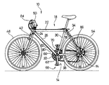
図1は、自転車用変速機における速度切換操作を補助するために、本発明による補助機構14の具体的一実施形態を組み入れた自転車10を示す側面図である。自転車10は、いかなる種類の自転車でもよく、この実施形態の自転車10は、トップチューブ22、ヘッドチューブ24、ヘッドチューブ24から下向きに延出するダウンチューブ26、トップチューブ22から下向きに延出するシートチューブ30、ダウンチューブ26とシートチューブ30との接合部に位置するボトムブラケット32、トップチューブ22から後方下向きに延出する1対のシートステイ34、及びボトムブラケット32から後方に延出する1対のチェーンステイ38を含む典型的フレーム18を有している。ヘッドチューブ24内にフォーク42が回転自在に支持されており、フォーク42の下方端部に前輪46が回転自在に支持されている。フォーク42及び前輪46の方向は、周知の方法でハンドルバー50が制御する。複数枚のスプロケット(図示せず)が同軸方向に取付けられた後輪54は、シートステイ34とチェーンステイ38との接合部に回転自在に支持されており、複数枚のフロントスプロケット(チェーンホイール)62を支持するペダルアセンブリ58が、ボトムブラケット32内で回転自在に支持されている。この実施形態では、3枚のフロントスプロケット62が、ペダルアセンブリ58と同軸状に一体回転する。チェーン66が、フロントスプロケット62の1枚と、後輪54に取付けられたフリーホイールスプロケットの1枚とに係合される。チェーン66の位置をフロントスプロケット62の1枚から別の1枚に移動させるのがフロントディレーラ70であり、チェーン66の位置をフリーホイールスプロケットの1枚から別の1枚に移動させるのがリアディレーラ74である。双方の操作は周知の通りである。この実施形態において、フロントディレーラ70の制御は、補助機構14に連結された出力制御ワイヤ78の引張り及び解除により行われ、補助機構14の制御は、ハンドルバー50左側に取付けられたシフト制御装置84に接続されているボーデン型制御ケーブル82のインナーワイヤ80により行われる。リアディレーラ74の制御は、従来通りの方法でボーデン型制御ケーブル86のインナーワイヤ80により行われる。
[Overall configuration of bicycle]
FIG. 1 is a side view showing a bicycle 10 incorporating a specific embodiment of an assist mechanism 14 according to the present invention to assist a speed switching operation in a bicycle transmission. The bicycle 10 may be any type of bicycle, and the bicycle 10 of this embodiment includes a top tube 22, a head tube 24, a down tube 26 extending downward from the head tube 24, and a seat extending downward from the top tube 22. The tube 30, a bottom bracket 32 located at a junction between the down tube 26 and the seat tube 30, a pair of seat stays 34 extending rearward and downward from the top tube 22, and a pair of chains extending rearward from the bottom bracket 32. It has a typical frame 18 including a stay 38. A fork 42 is rotatably supported in the head tube 24, and a front wheel 46 is rotatably supported at a lower end of the fork 42. The direction of fork 42 and front wheel 46 is controlled by handlebar 50 in a well-known manner. A rear wheel 54 on which a plurality of sprockets (not shown) are mounted coaxially is rotatably supported at a joint between the seat stay 34 and the chain stay 38, and a plurality of front sprockets (chain wheels). A pedal assembly 58 supporting 62 is rotatably supported within the bottom bracket 32. In this embodiment, three front sprockets 62 rotate coaxially with the pedal assembly 58. A chain 66 is engaged with one of the front sprockets 62 and one of the freewheel sprockets attached to the rear wheel 54. The front derailleur 70 moves the position of the chain 66 from one of the front sprockets 62 to another one, and the rear derailleur 74 moves the position of the chain 66 from one of the freewheel sprockets to another. It is. Both operations are well known. In this embodiment, control of the front derailleur 70 is performed by pulling and releasing an output control wire 78 connected to the auxiliary mechanism 14, and control of the auxiliary mechanism 14 is performed by a shift control device 84 attached to the left side of the handlebar 50. This is performed by the inner wire 80 of the Bowden control cable 82 connected to The control of the rear derailleur 74 is performed by the inner wire 80 of the Bowden control cable 86 in a conventional manner.
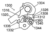
[シフト制御装置]
図2は、シフト制御装置84を示す、ハンドルバー50左側のより詳細な図であり、図3は、シフト制御装置84の分解図である。この実施形態において、シフト制御装置84は、固定式ハンドグリップ92とブレーキレバー98を支持する従来型ブレーキレバーブラケット94との間に取り付けられている。シフト制御装置84は、基部部材102と、クランプバンド106と、バネ110の形態である付勢部材と、中間部材114と、作動部材118と、保持器122とを含む。基部部材102は、ハンドルバー50を取り囲んでいる管状部分126と、管状部分126の内側端部から半径方向外向きに延出しているフランジ部分130とを含む。クランプバンド106は、固定突起部134と取付耳部138及び142を有しており、この構造が、環状凹部(図示せず)内でフランジ部分130の内周面に形成された固定溝と嵌合するようになっている。ネジ144を、フランジ部分130の開口148内と取付耳部138及び142内とに延在させ、フランジ部分に設けられたもう1つの開口153に位置するナット152内にねじ込むことにより、取付耳部138及び142を相互に向き合う方向に締付けて、クランプバンド106を締め、基部部材102をハンドルバー50に固定する。従来のネジ型である調節式コントロールケーブル連結器156がフランジ部分130上に配置されており、これにより、コントロールケーブル82のアウターケーシング81を従来通りの方法で収容することができるようになっている。当接部160a及び160bを有する、直径方向に対向して位置する凹部160(図3では一方のみを図示)が、管状部分126とフランジ部分130との接合部に形成されており、基部部材付勢係合部164が、バネ穴の形態で、フランジ部分130に形成されている。このバネ穴164内に、バネ110の端部168が嵌合される。
[Shift control device]
FIG. 2 is a more detailed view of the left side of the handlebar 50 showing the shift control device 84, and FIG. 3 is an exploded view of the shift control device 84. In this embodiment, the shift control device 84 is mounted between a fixed handgrip 92 and a conventional brake lever bracket 94 that supports a brake lever 98. The shift control device 84 includes a base member 102, a clamp band 106, a biasing member in the form of a spring 110, an intermediate member 114, an operating member 118, and a retainer 122. The base member 102 includes a tubular portion 126 surrounding the handlebar 50 and a flange portion 130 extending radially outward from an inner end of the tubular portion 126. The clamp band 106 has a fixing protrusion 134 and mounting ears 138 and 142, and this structure fits into a fixing groove formed on the inner peripheral surface of the flange portion 130 in an annular concave portion (not shown). Are adapted to each other. A screw 144 extends into the opening 148 of the flange portion 130 and into the mounting ears 138 and 142 and is screwed into a nut 152 located in another opening 153 provided in the flange portion to provide a mounting ear. Tighten 138 and 142 in opposite directions to tighten clamp band 106 and secure base member 102 to handlebar 50. A conventional threaded adjustable control cable coupler 156 is disposed on the flange portion 130 so that the outer casing 81 of the control cable 82 can be accommodated in a conventional manner. . A diametrically opposed recess 160 (only one is shown in FIG. 3) having abutments 160a and 160b is formed at the junction between the tubular portion 126 and the flange portion 130 and includes a base member. A biasing engagement portion 164 is formed in the flange portion 130 in the form of a spring hole. An end 168 of the spring 110 is fitted into the spring hole 164.
中間部材114は、バネ110がこの中間部材114と基部部材102のフランジ部分130との間に位置するように、基部部材102の管状部分126周囲に回動自在に支持されている。当接部172a及び172bを形成している、直径方向に対向して位置する突起またはストッパ172(図3では一方のみを図示)が、中間部材114の内側端部から軸方向に延出しており、当接部188a及び188bを形成している、直径方向に対向して位置する1対の突起またはストッパ188が、中間部材114の外周面184から半径方向外向きに延出している。バネ110の端部192は、中間部材114を時計回りに付勢するように、ストッパ188の一方に形成されたバネ開口194(これが、中間部材付勢係合部として機能する)内に嵌合されている。この構造により、ストッパ172の当接部172aが、当接部160a(これが基部部材ストッパとして機能する)に係合すると、中間部材114の基部部材102に対する回転を制限できるようになっている。
The intermediate member 114 is rotatably supported around a tubular portion 126 of the base member 102 such that the spring 110 is located between the intermediate member 114 and the flange portion 130 of the base member 102. Diametrically opposed protrusions or stoppers 172 (only one is shown in FIG. 3) forming the abutments 172a and 172b extend axially from the inner end of the intermediate member 114. A pair of diametrically opposed protrusions or stoppers 188 forming the contact portions 188a and 188b extend radially outward from the outer peripheral surface 184 of the intermediate member 114. The end 192 of the spring 110 fits into a spring opening 194 (which functions as an intermediate member urging engagement portion) formed in one of the stoppers 188 so as to urge the intermediate member 114 clockwise. Have been. With this structure, when the contact portion 172a of the stopper 172 engages with the contact portion 160a (which functions as a base member stopper), rotation of the intermediate member 114 with respect to the base member 102 can be limited.
作動部材118は、中間部材114により回動自在に支持されており、中間部材114は、上述したように、基部部材102の管状部材126により回転自在に支持されている。したがって、作動部材118は、中間部材114、基部部材102の管状部分126及びハンドルバー50の周囲を同軸状に回転することができる。作動部材118は、管状部材200と、管状部材200から半径方向外向きに延出する第1及び第2のレバー204及び208と、開口212の形態をとるケーブル連結部と、直径方向に対向して位置する凹部216とを含む。開口212としてのケーブル連結部は、インナーワイヤ80が作動部材118と一体移動するように、インナーワイヤ80の端部に装着されたケーブル端部ビード(図示せず)を収容するためのものである。また、凹部216は、当接部216a及び216bを形成している。これらを組立てると、中間部材ストッパ188が、当接部216aと216bとの間で対応凹部216内に嵌合するため、当接部216a及び216bは作動部材ストッパとして機能する。この実施形態において、コントロールケーブル82のインナーワイヤ80は、補助装置14内に配置された付勢部材の作用により張力下におかれている。したがって、作動部材118は、反時計回りの方向に付勢され、これにより、中間部材ストッパ188の当接部188aが当接部216aに係合して、基部部材102の中間部材114に対する作動部材118の回転を制限するようになっている。
The operating member 118 is rotatably supported by the intermediate member 114, and the intermediate member 114 is rotatably supported by the tubular member 126 of the base member 102, as described above. Thus, the actuating member 118 can rotate coaxially about the intermediate member 114, the tubular portion 126 of the base member 102, and the handlebar 50. The actuating member 118 is diametrically opposed to a tubular member 200, first and second levers 204 and 208 extending radially outward from the tubular member 200, a cable connection in the form of an opening 212. And a concave portion 216 positioned at The cable connection part as the opening 212 is for accommodating a cable end bead (not shown) attached to the end of the inner wire 80 so that the inner wire 80 moves integrally with the operating member 118. . Further, the concave portion 216 forms the contact portions 216a and 216b. When these are assembled, the intermediate member stopper 188 fits into the corresponding concave portion 216 between the contact portions 216a and 216b, so that the contact portions 216a and 216b function as an operating member stopper. In this embodiment, the inner wire 80 of the control cable 82 is under tension by the action of a biasing member disposed in the auxiliary device 14. Accordingly, the operating member 118 is urged in the counterclockwise direction, whereby the contact portion 188a of the intermediate member stopper 188 engages with the contact portion 216a, and the operating member relative to the intermediate member 114 of the base member 102. The rotation of 118 is limited.
保持器122は、基部部材102が含む管状部材126の外側端部周囲に嵌合するものである。保持器122は、基部部材102が含む管状部分126の外側端部から半径方向外向きに延出する4つの固定タブ228を係合するように、側部表面224に4つの凹部220を均等に有している。したがって、保持器122により、作動部材118及び中間部材114は、基部部材102の周囲にて軸方向一定位置に固定される。
The retainer 122 fits around the outer end of the tubular member 126 included in the base member 102. The retainer 122 equally has four recesses 220 on the side surface 224 to engage four securing tabs 228 extending radially outward from the outer end of the tubular portion 126 included in the base member 102. Have. Therefore, the operating member 118 and the intermediate member 114 are fixed at a fixed position in the axial direction around the base member 102 by the retainer 122.
[シフト制御装置の操作]
図4A〜図4Cは、シフト制御装置84の操作を概略的に図示したものである。図4Aに示した作動部材118は作動部材初期位置にある。この位置では、バネ110が中間部材114を時計回り(図4Aでは右)に付勢しているため、ストッパ172の当接部172aが、基部部材102に形成された凹部160の当接部160aに接触し、補助機構14内の付勢部材(バネ232)が、作動部材118を反時計回り方向に付勢するため、凹部216の当接部216aが中間部材ストッパ188の当接部188aに接触する。したがって、当接部169a、172a、188a及び216a(及びバネ110及び232のある程度)が、初期位置位置決め機構として機能する。インナーワイヤ80は作動部材118に直接連結されているため、インナーワイヤ80もこのとき同様に、ケーブル取付部材初期位置にある。
[Operation of shift control device]
4A to 4C schematically show the operation of the shift control device 84. The actuating member 118 shown in FIG. 4A is in the actuating member initial position. At this position, the spring 110 urges the intermediate member 114 clockwise (right in FIG. 4A), so that the contact portion 172a of the stopper 172 is in contact with the contact portion 160a of the concave portion 160 formed in the base member 102. And the urging member (spring 232) in the auxiliary mechanism 14 urges the operating member 118 in the counterclockwise direction, so that the contact portion 216a of the concave portion 216 contacts the contact portion 188a of the intermediate member stopper 188. Contact. Therefore, the contact portions 169a, 172a, 188a, and 216a (and some of the springs 110 and 232) function as an initial position positioning mechanism. Since the inner wire 80 is directly connected to the operating member 118, the inner wire 80 is also at the initial position of the cable attachment member at this time.
補助機構14内の付勢部材232の付勢力に対抗して、図4Aに示した位置から時計回りに作動部材118を回転させることにより、作動部材118の当接部216bは、図4Bに示すように、中間部材ストッパ188の当接部188bに接触する。このとき、中間部材114は静止したままである。図4Bにおいて、作動部材118は、作動部材ダウンシフト位置にあり、インナーワイヤ80は、ケーブルダウンシフト位置に引き込まれた状態となる。
By rotating the operating member 118 clockwise from the position shown in FIG. 4A against the urging force of the urging member 232 in the auxiliary mechanism 14, the contact portion 216b of the operating member 118 is shown in FIG. 4B. As described above, the contact portion 188b of the intermediate member stopper 188 contacts the contact portion 188b. At this time, the intermediate member 114 remains stationary. In FIG. 4B, the operating member 118 is in the operating member downshift position, and the inner wire 80 is in a state of being retracted to the cable downshift position.
図4Aに示した位置から反時計回りに作動部材118を回転させると、当接部216aが中間部材ストッパ188の当接部188aに接触し、結局、バネ110が作動部材118と基部部材102との間で連結された状態となるため、中間部材114が、バネ110の付勢力に対抗して反時計回り(図4Cにおいて左)に回転する。これにより、作動部材118は作動部材アップシフト位置に位置し、インナーワイヤ80は、ケーブルアップシフト位置に解除される。
When the operating member 118 is rotated counterclockwise from the position shown in FIG. 4A, the abutting portion 216a comes into contact with the abutting portion 188a of the intermediate member stopper 188, and the spring 110 eventually turns the operating member 118 and the base member 102 into contact with each other. Thus, the intermediate member 114 rotates counterclockwise (left in FIG. 4C) against the urging force of the spring 110. Thereby, the operation member 118 is located at the operation member upshift position, and the inner wire 80 is released to the cable upshift position.
[補助機構]
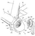
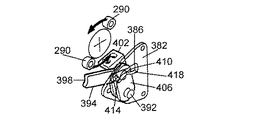
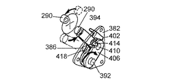
図5は、補助機構14をさらに詳しく示す図である。図5に示すように、補助機構14はボトムブラケット32に取付けられており、入力ユニット250と、位置決めユニット254と、回転部材係合ユニット258と、これに取り付けられたカバー262とを含む。この実施形態において、補助機構14は、クランクアーム266と併用されている。クランクアーム266は駆動軸取付ボス270を有している。駆動軸取付ボス270はクランクアームスプライン274を有しており、このクランクアームスプライン274に、ボトムブラケット32に回転自在に支持される駆動軸282の端部に形成された駆動軸スプライン278が回転不能に係合される。また、駆動フランジ286が、駆動軸取付ボス270から半径方向外向きに延出して形成されており、この駆動フランジ286に、半径方向に対向して位置する1対の回転部材290を支持している。1対の回転部材290は駆動部材として機能しており、この駆動部材290は、駆動フランジ286の側部表面294から垂直に延出する円形チューブの形状である。
[Auxiliary mechanism]
FIG. 5 is a diagram showing the auxiliary mechanism 14 in more detail. As shown in FIG. 5, the auxiliary mechanism 14 is attached to the bottom bracket 32, and includes an input unit 250, a positioning unit 254, a rotating member engaging unit 258, and a cover 262 attached thereto. In this embodiment, the auxiliary mechanism 14 is used together with the crank arm 266. The crank arm 266 has a drive shaft mounting boss 270. The drive shaft mounting boss 270 has a crank arm spline 274, on which a drive shaft spline 278 formed at the end of a drive shaft 282 rotatably supported by the bottom bracket 32 is non-rotatable. Engaged. Further, a drive flange 286 is formed to extend radially outward from the drive shaft mounting boss 270, and the drive flange 286 supports a pair of rotating members 290 which are positioned opposite to each other in the radial direction. I have. A pair of rotating members 290 function as a drive member, which is in the form of a circular tube extending vertically from a side surface 294 of the drive flange 286.
[補助機構−入力ユニット]
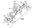
図6は、入力ユニット250の具体的な一実施形態を示す分解図である。入力ユニット250は、入力ユニット取付部材298と、ワイヤ連結部材302と、バネ232と、入力リンク306とを含む。入力ユニット取付部材298は、インナーワイヤ80用ガイドチャネル310と、位置決めユニット254の駆動軸318(図10)を内部に収容する中央駆動軸開口314と、直径方向に対向して位置する1対の開口322(図6に一方のみを図示)とを有する。ワイヤ連結部材302は、インナーワイヤ80の巻取り及び伸張を行うワイヤ巻取り溝326と、ネジ334の形態である従来型ワイヤ連結器330と、ワイヤ保持器338と、インナーワイヤ80をワイヤ連結部材302に固定するナット342と、位置決めユニット254の駆動軸318を収容する駆動軸開口346とを含む。入力リンク306は、ワイヤ連結部材302の回転位置を位置決めユニット254に伝達する役割を果たすものであり、駆動軸収容開口352を設けた駆動軸取付部分350と、連結タブ354と、半径方向に延出する部分358と、軸方向に延出する連結部分362とを含む。連結タブ354は、駆動軸取付部分350から軸方向に延出して、入力ユニット取付部材298の開口322内及びワイヤ連結部材302の対応開口(図示せず)内に挿入されることにより、連結部材302と入力リンク306とをユニットとして回転させるものである。したがって、連結部材302と入力リンク306とは共に、シフト制御装置84の作動部材118の位置に対応して、初期、アップシフト及びダウンシフトの位置をとることになる。ワイヤ連結部材302と入力リンク306とを時計回り(ワイヤ巻取り)方向に付勢するように、バネ232の一方の端部233は、ワイヤ連結部材302に取付けられ、もう一方の端部234は入力ユニット取付部材298に取付けられている。
[Auxiliary mechanism-Input unit]
FIG. 6 is an exploded view illustrating a specific embodiment of the input unit 250. The input unit 250 includes an input unit mounting member 298, a wire connecting member 302, a spring 232, and an input link 306. The input unit mounting member 298 includes a guide channel 310 for the inner wire 80, a central drive shaft opening 314 that houses the drive shaft 318 (FIG. 10) of the positioning unit 254 therein, and a pair of diametrically opposed pairs. And an opening 322 (only one is shown in FIG. 6). The wire connecting member 302 includes a wire winding groove 326 for winding and extending the inner wire 80, a conventional wire connector 330 in the form of a screw 334, a wire retainer 338, and a wire connecting member. It includes a nut 342 fixed to 302 and a drive shaft opening 346 for accommodating the drive shaft 318 of the positioning unit 254. The input link 306 serves to transmit the rotational position of the wire connection member 302 to the positioning unit 254, and includes a drive shaft mounting portion 350 having a drive shaft receiving opening 352, a connection tab 354, and a radial extension. And a connecting portion 362 extending in the axial direction. The connection tab 354 extends in the axial direction from the drive shaft mounting portion 350 and is inserted into the opening 322 of the input unit mounting member 298 and the corresponding opening (not shown) of the wire connecting member 302 so that the connecting member is connected. The input 302 and the input link 306 are rotated as a unit. Accordingly, both the connecting member 302 and the input link 306 assume the initial, upshift, and downshift positions corresponding to the position of the operating member 118 of the shift control device 84. One end 233 of the spring 232 is attached to the wire connecting member 302, and the other end 234 is urged to urge the wire connecting member 302 and the input link 306 in the clockwise (wire winding) direction. It is attached to the input unit attachment member 298.
[補助機構−回転部材係合ユニット]
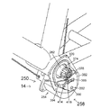
図7は、回転部材係合ユニット258のカバー262を取り外した、補助機構を示す斜視図であり、図8は補助機構14を示す背面断面図であり、図9A〜図9Dは回転部材係合ユニット258の操作を示す図である。図7、図8及び図9Aに示すように、回転部材係合ユニット258は、内部に駆動軸282を収容する開口374を有するボトムブラケット取付部材370(図7)と、軸方向に延在する側部壁378と、制御カムスロット386を有し側部壁378に装着されたカムプレート382と、下方回動軸392を支持する開口390とを含む。回転部材係合部材394の第1の端部部分391(図21)は、この実施形態ではレバー形状であり、クランクアーム266上の駆動部材290を係合するための弓状回転部材係合面398を有する。回転部材係合部材394の第2の端部(図21)は、回動軸410(図8及び図9A)により位置決めユニットインターフェースプレート402と支持プレート406との間(これらが動力伝達部材として機能する)で回動自在に接続されて、回転部材係合リンクを形成している。この回転部材係合部材394の第1の端部部分と第2の端部部分との間に、特に、回動軸410の極めて近くにカムフォロア414が配置されている。カムフォロア414は、カムスロット386により形成された制御カム表面418に係合するものである。バネ420(図8)が、位置決めユニットインターフェースプレート402及び支持プレート406を反時計回り方向に付勢する。この実施形態では、位置決めユニットインターフェースプレート402、支持プレート406、カムフォロア414及び制御カム表面418を、回転部材係合部材394を回転部材係合位置に固定し、回転部材係合部材394を回転部材非係合位置に向けて復帰させる固定機構407と見なすことができる。無論、適した固定機構を形成するために、数多くの構造体を組合わせることができる。また、カムフォロア414は回転部材係合部材394上に設けられているが、カムフォロアをスロット386内に配置し、制御カムを回転部材係合部材394上に設けることも可能である。
[Auxiliary mechanism-Rotating member engaging unit]
FIG. 7 is a perspective view showing the auxiliary mechanism with the cover 262 of the rotating member engaging unit 258 removed, FIG. 8 is a rear cross-sectional view showing the auxiliary mechanism 14, and FIGS. FIG. 17 is a diagram showing the operation of the unit 258. As shown in FIGS. 7, 8 and 9A, the rotating member engaging unit 258 includes a bottom bracket mounting member 370 (FIG. 7) having an opening 374 for accommodating the drive shaft 282 therein, and a side extending in the axial direction. It includes a section wall 378, a cam plate 382 having a control cam slot 386 mounted on the side wall 378, and an opening 390 for supporting the lower pivot 392. The first end portion 391 (FIG. 21) of the rotating member engaging member 394 is lever-shaped in this embodiment and has an arcuate rotating member engaging surface for engaging the driving member 290 on the crank arm 266. 398. A second end (FIG. 21) of the rotating member engaging member 394 is moved between the positioning unit interface plate 402 and the support plate 406 by a rotating shaft 410 (FIGS. 8 and 9A) (these functions as a power transmission member). ) To form a rotating member engaging link. A cam follower 414 is arranged between the first end portion and the second end portion of the rotating member engaging member 394, particularly, very close to the rotation shaft 410. The cam follower 414 engages a control cam surface 418 formed by the cam slot 386. A spring 420 (FIG. 8) biases the positioning unit interface plate 402 and the support plate 406 in a counterclockwise direction. In this embodiment, the positioning unit interface plate 402, the support plate 406, the cam follower 414, and the control cam surface 418 are fixed to the rotating member engaging member 394 at the rotating member engaging position, and the rotating member engaging member 394 is not rotated. It can be considered as a fixing mechanism 407 that returns to the engagement position. Of course, numerous structures can be combined to form a suitable locking mechanism. Although the cam follower 414 is provided on the rotating member engaging member 394, it is also possible to arrange the cam follower in the slot 386 and provide the control cam on the rotating member engaging member 394.
図9Aは、回転部材非係合位置にある回転部材係合部材394を示したものである。この位置において、駆動部材290は、補助機構14に何の作用も及ぼさずにクランクアーム266と共に回転する。一般に、シフト制御ユニット84の作動部材118が、アップシフト位置かダウンシフト位置かの一方に回転させられると、位置決めユニットインターフェースプレート402及び支持プレート406が図9Bに示すように反時計回りに回動する。これにより、カムフォロア414がカムスロット386内にて図9Bに示す回転部材係合位置に留まるため、回転部材係合部材394が回動軸410を中心に時計回りに回動する。この位置において、回転部材係合面398が駆動部材290の通路内にくるため、駆動部材290の1つが、図9Bに示すように回転部材係合面398に接触し、回転部材係合部材394が位置決めユニットインターフェースプレート402及び支持プレート406を、図9Cに示すように、バネ420の付勢力に対抗して時計回りに回転させることになる。クランクアーム266が回転を続けると、係合されていた駆動部材290が回転部材係合部材394からはずされるため、図9Dに示すように、回転部材係合部材394は回転部材非係合位置に戻るように反時計回りに回動し、バネ420が位置決めユニットインターフェースプレート402及び支持プレート406を、図9Aに示す位置に戻るように反時計回りに回動させることになる。
FIG. 9A shows the rotating member engaging member 394 in the rotating member non-engaging position. In this position, the drive member 290 rotates with the crank arm 266 without affecting the auxiliary mechanism 14. Generally, when the operating member 118 of the shift control unit 84 is rotated to one of the upshift position and the downshift position, the positioning unit interface plate 402 and the support plate 406 rotate counterclockwise as shown in FIG. 9B. I do. This causes the cam follower 414 to stay at the rotating member engaging position shown in FIG. 9B within the cam slot 386, so that the rotating member engaging member 394 rotates clockwise about the rotating shaft 410. In this position, the rotating member engaging surface 398 is in the path of the driving member 290 so that one of the driving members 290 contacts the rotating member engaging surface 398 as shown in FIG. Will rotate the positioning unit interface plate 402 and the support plate 406 clockwise against the urging force of the spring 420, as shown in FIG. 9C. As the crank arm 266 continues to rotate, the engaged driving member 290 is disengaged from the rotating member engaging member 394, and as shown in FIG. 9D, the rotating member engaging member 394 is moved to the rotating member non-engaging position. Then, the spring 420 rotates the positioning unit interface plate 402 and the support plate 406 counterclockwise to return to the position shown in FIG. 9A.
[補助機構−位置決めユニット]
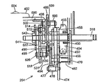
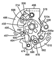
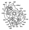
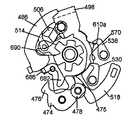
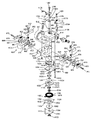
図10は、位置決めユニット254の内部の構成を示す拡大背面断面図であり、図16Aは、位置決めユニット254が含む内部の構成の一部を示す側面図である。図10に示すように、位置決めユニット254は、爪軸470の一方の端部を支持する基部プレート450と、回転部材454(出力伝達部材)と、バネ456(付勢部材)と、位置決めラチェット458(位置決め部材)とを含む。回転部材454は、駆動軸318を中心に回転自在に支持され、複数の出力位置に対して出力制御ワイヤ78の巻取り及び解除を行うためのワイヤ巻取り溝455を有する。バネ456はワイヤ解除方向に回転部材454を付勢する。位置決めラチェット458は、回転部材454に、これと一体となって回転できるように連結されている。
[Auxiliary mechanism-Positioning unit]
FIG. 10 is an enlarged rear cross-sectional view showing the internal configuration of the positioning unit 254, and FIG. 16A is a side view showing a part of the internal configuration included in the positioning unit 254. As shown in FIG. 10, the positioning unit 254 includes a base plate 450 supporting one end of the claw shaft 470, a rotating member 454 (output transmission member), a spring 456 (biasing member), and a positioning ratchet 458. (Positioning member). The rotating member 454 is rotatably supported about the drive shaft 318, and has a wire winding groove 455 for winding and releasing the output control wire 78 at a plurality of output positions. The spring 456 urges the rotating member 454 in the wire releasing direction. The positioning ratchet 458 is connected to the rotating member 454 so as to be able to rotate integrally therewith.
また、位置決めユニット254は、爪軸470のもう一方の端部を支持する中間プレート466と、位置保持位置と位置解除位置との間で回転できるように爪軸470により支持され、位置決め歯475及び476(図16A)を有する位置決め爪474(位置保持部材)と、位置決め歯475に取付けられた回動軸477と、回動軸477により回転自在に支持されたカムローラ478(カムフォロア)と、位置決め爪474を位置保持位置に向けて(図16Aにおける反時計回りに)付勢するように、位置決め爪474と基部プレート450との間に接続された爪用バネ482とを含む。
The positioning unit 254 is supported by the intermediate plate 466 supporting the other end of the claw shaft 470 and the claw shaft 470 so as to be rotatable between a position holding position and a position release position. A positioning claw 474 (position holding member) having 476 (FIG. 16A), a rotating shaft 477 attached to the positioning teeth 475, a cam roller 478 (cam follower) rotatably supported by the rotating shaft 477, and a positioning claw. A pawl spring 482 is connected between the positioning pawl 474 and the base plate 450 to bias the 474 toward the holding position (counterclockwise in FIG. 16A).
位置決めユニット254はさらに、解除プレート486と、伝動部材498と、爪軸502と、伝動爪506と、バネ509と、爪軸510と、モード切換爪514とを有している。解除プレート486は、駆動軸318を中心に回転自在に支持され、カムプレート494の形態であるカム部材を支持する回動軸490を有している。伝動部材498は駆動軸318を中心に回転自在に支持されている。爪軸502は伝動部材498に取付けられている。伝動爪506は爪軸502を中心に回動自在に支持されている。バネ509は伝動爪506を図16Aにおける反時計回りに付勢する。爪軸510は伝動部材498に取付けられている。モード切換爪514は爪軸510を中心に回動自在に支持されている。
The positioning unit 254 further includes a release plate 486, a transmission member 498, a claw shaft 502, a transmission claw 506, a spring 509, a claw shaft 510, and a mode switching claw 514. The release plate 486 is rotatably supported about a drive shaft 318 and has a rotation shaft 490 that supports a cam member in the form of a cam plate 494. The transmission member 498 is supported rotatably about the drive shaft 318. The pawl shaft 502 is attached to the transmission member 498. The transmission pawl 506 is supported rotatably about the pawl shaft 502. The spring 509 urges the transmission claw 506 counterclockwise in FIG. 16A. The pawl shaft 510 is attached to the transmission member 498. The mode switching claw 514 is supported rotatably about the claw shaft 510.
さらに位置決めユニット254は、駆動軸318を中心に回転自在に支持された制御プレート518(入力伝達部材)と、基部プレート522と、基部プレート522に取り付けられた駆動制御爪530(スイッチオフ駆動制御部材)を支持する爪軸526と、図16Aにおける反時計回りに駆動制御爪530を付勢するバネ531と、基部プレート522に取付けられた駆動制御爪538(スイッチオン駆動制御部材)を支持する爪軸534(図16A)と、図16Aにおける反時計回りに駆動制御爪538を付勢するバネ539と、バネ保持器541と、図16Aにおける時計回り方向に伝動部材498を付勢するように、バネ保持器541と伝動部材498との間で接続されたバネ499と、駆動軸318を中心にこれらの構成部材を軸方向に保持するための保持ナット542とを含む。基部プレート450、基部プレート522及び駆動軸318が、さまざまな構成部材に対する取付ユニットとして機能している。
Further, the positioning unit 254 includes a control plate 518 (input transmission member) rotatably supported around the drive shaft 318, a base plate 522, and a drive control claw 530 (switch-off drive control member) attached to the base plate 522. 16), a spring 531 for urging the drive control claw 530 counterclockwise in FIG. 16A, and a claw supporting a drive control claw 538 (switch-on drive control member) attached to the base plate 522. A shaft 534 (FIG. 16A), a spring 539 for urging the drive control claw 538 in a counterclockwise direction in FIG. 16A, a spring retainer 541 and a transmission member 498 in a clockwise direction in FIG. A spring 499 connected between the spring retainer 541 and the transmission member 498, and these components around the drive shaft 318 And a retaining nut 542 for holding the direction. The base plate 450, the base plate 522, and the drive shaft 318 function as a mounting unit for various components.
<伝動部材498>
図11は、伝動部材498を示す側面図である。伝動部材498は、基部部分550と、爪取付け耳部554と、伝動アーム558とを含む。基部部分550は、駆動軸318を内部に収容する開口562と、駆動制御爪530に接触する当接部570を形成している半径方向外向きに延出した突起566と、駆動制御爪538に接触する当接部578を形成している半径方向外向きに延出する突起574とを含む。爪取付け耳部554は、爪軸(モード切換爪514を支持する)510を取り付けるための開口582を含み、伝動アーム558も同様に、爪軸(伝動爪506を支持する)502を取り付けるための開口586を含む。伝動アーム558はまた、駆動制御爪539に接触する当接部588と、図8及び図10に示すように、ネジ594を介して位置決めユニットインターフェースプレート402に装着される、軸方向に延出する回転部材係合ユニットインターフェースプレート590とを含む。
<Transmission member 498>
FIG. 11 is a side view showing the transmission member 498. The transmission member 498 includes a base portion 550, a pawl mounting ear 554, and a transmission arm 558. The base portion 550 includes an opening 562 that accommodates the drive shaft 318 therein, a radially outwardly extending protrusion 566 that forms a contact portion 570 that contacts the drive control claw 530, and a drive control claw 538. A radially outwardly extending projection 574 forming an abutting portion 578 for contact. The claw mounting ear 554 includes an opening 582 for mounting a claw shaft (supporting the mode switching claw 514) 510, and the transmission arm 558 also has a claw shaft (supporting the transmission claw 506) 502 for mounting. An opening 586 is included. The transmission arm 558 also extends in the axial direction, which is mounted on the positioning unit interface plate 402 via a screw 594 as shown in FIGS. 8 and 10 and a contact portion 588 that contacts the drive control claw 539. And a rotation member engaging unit interface plate 590.
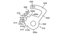
<制御プレート518>
図12は、制御プレート518の具体的一実施形態を示す側面図である。制御プレート518は、基部部分598の形態である入力制御部材と、レバーアーム部分602と、入力ユニットインターフェースプレート604とを含む。入力ユニットインターフェースプレート604には、入力リンク306の連結部分362(図6)を収容する開口605が設けられている。基部部分598は、半径方向に延出する駆動制御カム表面またはローブ606、610、614及び618の形態である入力制御部材を含む。駆動制御カムローブ606は、上方面606aと、傾斜スロープ606b及び606cとを含む。同様に、駆動制御カムローブ610は、上方面610aと、傾斜スロープ610b及び610cとを含む。駆動制御カムローブ614は、上方面614aと、傾斜スロープ614bと、上方面614aからカムローブ618の上方面618aまで延在する移行面614cとを含む。カムローブ618はさらに、上方面618aから基部部分598の外周面598aまで延在する移行面618bを含む。以下の記載から、カムローブ606、610、614及び618と、駆動制御爪538と、突起578を設けた伝動部材438とが、回転部材係合位置と回転部材非係合位置との間における回転部材係合部材394の移動を制御する切換機構をなしていることが明白になるであろう。
<Control plate 518>
FIG. 12 is a side view showing a specific embodiment of the control plate 518. The control plate 518 includes an input control member in the form of a base portion 598, a lever arm portion 602, and an input unit interface plate 604. The input unit interface plate 604 is provided with an opening 605 for accommodating the connecting portion 362 (FIG. 6) of the input link 306. The base portion 598 includes an input control member in the form of a radially extending drive control cam surface or lobe 606, 610, 614 and 618. Drive control cam lobe 606 includes an upper surface 606a and slopes 606b and 606c. Similarly, drive control cam lobe 610 includes an upper surface 610a and slopes 610b and 610c. The drive control cam lobe 614 includes an upper surface 614a, a ramp 614b, and a transition surface 614c extending from the upper surface 614a to an upper surface 618a of the cam lobe 618. Cam lobe 618 further includes a transition surface 618b extending from upper surface 618a to outer peripheral surface 598a of base portion 598. From the following description, it is understood that the cam lobes 606, 610, 614, and 618, the drive control pawl 538, and the transmission member 438 provided with the protrusion 578 are provided between the rotation member engaging position and the rotation member non-engaging position. It will be apparent that the switching mechanism controls the movement of the engagement member 394.
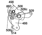
<中間プレート466>
図13は、中間プレート466の具体的一実施形態を示す側面図である。中間プレート466は、基部部分630と、爪連結アーム634と、ダウンシフト制御プレート638と、ダウンシフト制御プレート638から延出する爪連結部分642とを含む。爪連結アーム634は、このアセンブリを筐体に装着するのに使用する固定具(図示せず)を収容する開口646を含み、爪連結部分642は、爪軸(位置決め爪474を支持する)470を装着する開口650を含む。ダウンシフト制御プレート638は、以下に説明するように機能する爪制御面660を有する凹部656を構成している。
<Intermediate plate 466>
FIG. 13 is a side view showing a specific embodiment of the intermediate plate 466. The intermediate plate 466 includes a base portion 630, a pawl connection arm 634, a downshift control plate 638, and a pawl connection portion 642 extending from the downshift control plate 638. The pawl coupling arm 634 includes an opening 646 for receiving a fixture (not shown) used to mount the assembly to the housing, and the pawl coupling portion 642 has a pawl shaft (supporting the positioning pawl 474) 470. And an opening 650 for mounting. Downshift control plate 638 defines a recess 656 having a pawl control surface 660 that functions as described below.
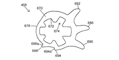
<位置決めラチェット458>
図14は、位置決めラチェット458を示す側面図である。位置決めラチェット458は、位置決めラチェット458と回転部材454とをユニットとして回転させるために、回転部材454に形成された複数の対応雄スプライン(図示せず)を回転不能に係合する複数の雌スプライン674を内周面672に形成した略環状本体670を有する。外周面678は、3つの位置決め歯682、686及び690と、駆動面694a及び698aをそれぞれ構成する2つの駆動歯694及び698とを形成している。この構造により、回転部材454を、3枚のフロントスプロケット62に適合する3つの位置に固定することができる。このスプロケットは通常、小径スプロケットと、中径スプロケットと、大径スプロケットとを含む。
<Positioning ratchet 458>
FIG. 14 is a side view showing the positioning ratchet 458. The positioning ratchet 458 includes a plurality of female splines 674 that non-rotatably engage a plurality of corresponding male splines (not shown) formed on the rotating member 454 in order to rotate the positioning ratchet 458 and the rotating member 454 as a unit. Is formed on the inner peripheral surface 672. The outer peripheral surface 678 forms three positioning teeth 682, 686, and 690, and two driving teeth 694 and 698 that form driving surfaces 694a and 698a, respectively. With this structure, the rotating member 454 can be fixed at three positions that match the three front sprockets 62. The sprocket typically includes a small diameter sprocket, a medium diameter sprocket, and a large diameter sprocket.
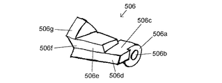
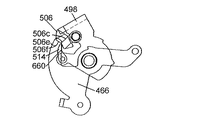
<伝動爪506>
図15は、伝動爪506を示す斜視図である。伝動爪506は、爪軸502を収容する開口506bを設けた基部部分506aと、以下に説明するように中間プレート466の爪制御面660に接触するダウンシフト制御面506cと、位置決めラチェット駆動面506dと、解除プレート駆動面506eと、モード切換爪接触面506f及び506gとを含む。
<Transmission claw 506>
FIG. 15 is a perspective view showing the transmission claw 506. The transmission claw 506 includes a base portion 506a provided with an opening 506b for accommodating the claw shaft 502, a downshift control surface 506c that contacts a claw control surface 660 of the intermediate plate 466 as described below, and a positioning ratchet drive surface 506d. , A release plate driving surface 506e, and mode switching claw contact surfaces 506f and 506g.
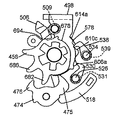
[位置決めユニットの操作−アップシフト]
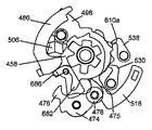
図16A〜図16Eは、アップシフト方向における位置決めユニット254の操作を示す図である。図16Aにおいて、位置決めユニット254は、フロントディレーラ70が小径フロントスプロケットの位置と一致するように配置された状態であり、フロントディレーラ70を中径フロントスプロケットまで移動させようとしているところである。図16Aで示した位置において、駆動制御爪530の先端部は、カムローブ606の上方面606aに支持され、駆動制御爪538の先端部は、カムローブ610が含むスロープ610cの底部に位置している。これにより、駆動制御爪538は、伝動部材498の当接部578と接触するため、伝動部材498を「スイッチオフ」位置に保持することができる。このように、駆動制御爪538及びカムローブ610が、伝動部材498を通常はスイッチオフ位置に維持しておく駆動制御機構をなしている。このとき、伝動爪506は、位置決めラチェット458が含む駆動歯694の上方面上で静止している。
[Operation of positioning unit-Upshift]
16A to 16E are diagrams showing the operation of the positioning unit 254 in the upshift direction. In FIG. 16A, the positioning unit 254 is in a state where the front derailleur 70 is arranged so as to coincide with the position of the small-diameter front sprocket, and is about to move the front derailleur 70 to the medium-diameter front sprocket. In the position shown in FIG. 16A, the tip of the drive control claw 530 is supported by the upper surface 606a of the cam lobe 606, and the tip of the drive control claw 538 is located at the bottom of the slope 610c included in the cam lobe 610. Accordingly, the drive control claw 538 contacts the contact portion 578 of the transmission member 498, so that the transmission member 498 can be held at the “switch off” position. Thus, drive control pawl 538 and cam lobe 610 form a drive control mechanism that keeps transmission member 498 normally in the switch off position. At this time, the transmission claw 506 is stationary on the upper surface of the drive tooth 694 included in the positioning ratchet 458.
そこで乗り手は、作動部材118を反時計回り(図3)にアップシフト位置まで回転させて、インナーワイヤ80を作動部材118により解除する。これにより、ワイヤ連結部材302が図6の時計回りに回転し、この動作が入力リンク306を介して制御プレート518に伝達されるため、制御プレート518が図16Bに示すアップシフト位置まで時計回りに回転する。制御プレート518が時計回りに回転することにより、駆動制御爪530がカムローブ606のスロープ606cを摺動して下降し、図16Bに示す位置まで反時計回りに回転する。これと同時に、駆動制御爪538が、伝動部材498の当接部578から離れてカムローブ614の上方面614a上で静止するまで、カムローブ614のスロープ614bを摺動して上昇する。駆動制御爪538が当接部578にもはや接触していないため、伝動部材498は、駆動制御爪538が当接部588に接触するまで時計回りに回転して、図16Bに示すように「スイッチオン」位置にくる。このとき、伝動爪506は、位置決めラチェット458上で駆動歯694に保持された状態ではなくなっているため、反時計回りに回転して、位置決めラチェット458の外周面678上で静止する。この伝動部材498の時計回り動作が、回転部材係合ユニット258内にて位置決めユニットインターフェースプレート402及び支持プレート406に伝達され、これにより、回転部材係合部材394が図9Bに示す位置まで回動する。
Then, the rider rotates the operating member 118 counterclockwise (FIG. 3) to the upshift position, and releases the inner wire 80 by the operating member 118. As a result, the wire connecting member 302 rotates clockwise in FIG. 6 and this operation is transmitted to the control plate 518 via the input link 306, so that the control plate 518 rotates clockwise to the upshift position shown in FIG. 16B. Rotate. When the control plate 518 rotates clockwise, the drive control pawl 530 slides down the slope 606c of the cam lobe 606, and rotates counterclockwise to the position shown in FIG. 16B. At the same time, the drive control claw 538 slides up the slope 614 b of the cam lobe 614 until it separates from the contact portion 578 of the transmission member 498 and stops on the upper surface 614 a of the cam lobe 614. Since the drive control claw 538 is no longer in contact with the abutment 578, the transmission member 498 rotates clockwise until the drive control claw 538 contacts the abutment 588, as shown in FIG. Comes to the "on" position. At this time, since the transmission claw 506 is no longer held on the positioning ratchet 458 by the driving teeth 694, it rotates counterclockwise and stops on the outer peripheral surface 678 of the positioning ratchet 458. The clockwise operation of the transmission member 498 is transmitted to the positioning unit interface plate 402 and the support plate 406 in the rotation member engagement unit 258, whereby the rotation member engagement member 394 is rotated to the position shown in FIG. 9B. I do.
クランクアーム266の駆動部材290が回転部材係合部材394を係合して、位置決めユニットインターフェースプレート402及び支持プレート406を図9Cに示す位置まで回動させると、この動作が伝動部材498に伝達される。そこで、伝動爪506の位置決めラチェット駆動面506dが、位置決めラチェット458の駆動歯694に係合して、位置決めラチェット458及び回転部材454を回転させることにより、出力制御ワイヤ78を巻き取る。この間、位置決め歯682は位置決め爪474の爪歯475に押付けられて、爪歯475が位置決め歯682の先端部を通過させるまで、位置決め爪474を時計方向に回転させる。通過し終わると、位置決め爪474は反時計回りに回転するため、爪歯475が、図16Cに示す位置決め歯682と686との間にくる。
When the driving member 290 of the crank arm 266 engages the rotating member engaging member 394 to rotate the positioning unit interface plate 402 and the support plate 406 to the positions shown in FIG. 9C, this operation is transmitted to the transmission member 498. You. Then, the positioning ratchet drive surface 506d of the transmission claw 506 engages with the drive teeth 694 of the positioning ratchet 458 to rotate the positioning ratchet 458 and the rotating member 454, thereby winding up the output control wire 78. During this time, the positioning teeth 682 are pressed against the pawl teeth 475 of the positioning claws 474, and rotate the positioning claws 474 clockwise until the pawl teeth 475 pass through the tips of the positioning teeth 682. After the passage, the positioning claw 474 rotates counterclockwise, so that the claw teeth 475 come between the positioning teeth 682 and 686 shown in FIG. 16C.
クランクアーム266の駆動部材290が回転部材係合部材からはずれると、位置決めユニットインターフェースプレート402及び支持プレート406が、図9Aに示す位置に回転して戻り、この動作が伝動部材498に伝達される。これにより、伝動爪506が位置決めラチェット458の駆動歯694から離れ、位置決めラチェット458及び回転部材454は、位置決め歯682が爪歯475に衝突するまで、バネ456の付勢力にしたがって時計回りに回転する。これと同時に、フロントディレーラ70が、所望通り、中径フロントスプロケットに一致するようになる。
When the driving member 290 of the crank arm 266 is disengaged from the rotating member engaging member, the positioning unit interface plate 402 and the support plate 406 rotate back to the positions shown in FIG. 9A, and this operation is transmitted to the transmission member 498. As a result, the transmission pawl 506 separates from the driving teeth 694 of the positioning ratchet 458, and the positioning ratchet 458 and the rotating member 454 rotate clockwise according to the urging force of the spring 456 until the positioning teeth 682 hit the pawl teeth 475. . At the same time, the front derailleur 70 matches the medium front sprocket as desired.
しかし、このとき、乗り手がまだ作動部材18を初期位置に戻していないと仮定すると、駆動制御爪538がカムローブ614の上方面614a上に静止した状態で、制御プレート518はまだアップシフト位置にある。この位置では、駆動制御爪538は、当接部578に係合することにより伝動部材498の回転を停止させることができない。したがって、伝動部材498は、図16Aに示すスイッチオフ位置に戻る代わりに、図16Bに示すスイッチオン位置まで回転を続け、回転部材係合部材394は、図9Bに示す回転部材係合位置に戻り、シフトがもう一度行われることになる。こうした操作は、用途によっては望ましく、これも本発明の範囲内である。しかし、この実施形態では、こうした2重シフトを避けるために駆動制御爪530が設けられている。具体的に言えば、駆動制御爪530は、上述したように反時計回りに回転しているため、こうした場合に伝動部材498の当接部570に接触する位置にきて、伝動部材498の回転を一時的に停止させる。これにより、伝動部材498を、図16Dに示す位置にできる。このように、駆動制御爪530及びカムローブ606は、伝動機構が回転部材係合部材394からの動作を回転部材454に伝達した後に伝動部材498がスイッチオン位置に回転して戻ることを阻止する駆動制御機構をなしている。
However, at this time, assuming that the rider has not yet returned the operating member 18 to the initial position, the control plate 518 is still in the upshift position with the drive control pawl 538 resting on the upper surface 614a of the cam lobe 614. . In this position, the drive control claw 538 cannot stop the rotation of the transmission member 498 by engaging with the contact portion 578. Therefore, instead of returning to the switch-off position shown in FIG. 16A, the transmission member 498 continues to rotate to the switch-on position shown in FIG. 16B, and the rotating member engaging member 394 returns to the rotating member engaging position shown in FIG. 9B. , The shift will take place again. Such an operation is desirable for some applications and is also within the scope of the present invention. However, in this embodiment, a drive control claw 530 is provided to avoid such a double shift. Specifically, since the drive control claw 530 rotates counterclockwise as described above, in such a case, the drive control claw 530 comes to a position where it comes into contact with the contact portion 570 of the transmission member 498, and the rotation of the transmission member 498 Is temporarily stopped. This allows the transmission member 498 to be at the position shown in FIG. 16D. As described above, the drive control pawl 530 and the cam lobe 606 serve to prevent the transmission member 498 from rotating back to the switch-on position after the transmission mechanism transmits the operation from the rotation member engagement member 394 to the rotation member 454. Has a control mechanism.
乗り手が作動部材118を初期位置に戻すと、制御プレート518が同様に、図16Eに示す初期位置まで回転して戻る。これと同時に、駆動制御爪530は、カムローブ606のスロープ606cを摺動して上昇し、制御爪530が伝動部材498の当接部570から離れて駆動制御爪530の先端部がカムローブ606の上方面606a上で静止するまで、時計方向に回転する。また、駆動制御爪538は、カムローブ614のスロープ614bを摺動して下降し、反時計回りに回転する。これにより、図16Eに示すように、駆動制御爪538の先端部は伝動部材498の当接部578に接触する。こうして、伝動部材498は、図16Aに元々示したようにスイッチオフ位置に戻るが、位置決めラチェット458及び回転部材454は、フロントディレーラ70を中径フロントスプロケットと整合させる位置となる。中径フロントスプロケットから大径フロントスプロケットにシフトさせる動作もこれと同様である。
When the rider returns the actuating member 118 to the initial position, the control plate 518 also rotates back to the initial position shown in FIG. 16E. At the same time, the drive control claw 530 slides up the slope 606 c of the cam lobe 606 and rises, so that the control claw 530 separates from the contact portion 570 of the transmission member 498 and the tip of the drive control claw 530 is positioned above the cam lobe 606. It rotates clockwise until it stops on direction 606a. Further, the drive control claw 538 slides down the slope 614b of the cam lobe 614 and descends, and rotates counterclockwise. Thereby, as shown in FIG. 16E, the tip of the drive control claw 538 contacts the contact portion 578 of the transmission member 498. Thus, the transmission member 498 returns to the switch off position as originally shown in FIG. 16A, but the positioning ratchet 458 and the rotating member 454 are in a position to align the front derailleur 70 with the medium diameter front sprocket. The operation of shifting from the medium-diameter front sprocket to the large-diameter front sprocket is similar to this.
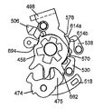
[位置決めユニットの操作−ダウンシフト]
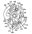
図17A〜図17Eは、位置決めユニット254のダウンシフト方向における操作を示す図である。ダウンシフト操作で重要な役割を果たす構成部材の操作がよくわかるように、いくつかの構成部材は透明なものとして図示している。回転部材454が、フロントディレーラ70が中径フロントスプロケットと一致する位置(図16Eに示した位置と同じ位置)にあり、フロントディレーラ70を小径スプロケットまで移動させたい状況を仮定すると、図17Aに示す位置において、駆動制御爪530の先端部はまたもやカムローブ606の上方面606aに支持されており、駆動制御爪538の先端部は、駆動制御爪538が伝動部材498の当接部578に接触するように、カムローブ610のスロープ610cの底部に位置している。伝動爪506は、位置決めラチェット458の駆動歯698の上方面上で静止している。全体に丸みを帯びた細長い二等辺三角形であるカムプレート494は、軸方向に延出する位置決めタブ495を含んでおり、このタブが解除プレート486の側部面487に衝突して、カムプレート494を図17Aに示す位置に保持している。
[Operation of positioning unit-downshift]
17A to 17E are views showing the operation of the positioning unit 254 in the downshift direction. Some components are shown as transparent to better illustrate the operation of the components that play an important role in the downshift operation. Assuming that the rotating member 454 is in a position where the front derailleur 70 coincides with the medium-diameter front sprocket (the same position as the position shown in FIG. 16E), and it is desired to move the front derailleur 70 to the small-diameter sprocket, FIG. In this position, the tip of the drive control claw 530 is again supported on the upper surface 606 a of the cam lobe 606, and the tip of the drive control claw 538 contacts the abutment 578 of the transmission member 498. The cam lobe 610 is located at the bottom of the slope 610c. The transmission pawl 506 is stationary on the upper surface of the drive teeth 698 of the positioning ratchet 458. The cam plate 494, which is a generally rounded elongated isosceles triangle, includes an axially extending locating tab 495 that collides with a side surface 487 of the release plate 486, thereby causing the cam plate 494 to squeeze. At the position shown in FIG. 17A.
そこで乗り手は、作動部材118を時計回り図3にダウンシフト位置まで回転させて、インナーワイヤ80を作動部材118で引っ張る。これにより、ワイヤ連結部材302は図6の反時計回りに回転し、この動作が入力リンク306を介して制御プレート518に伝達されるため、制御プレート518は図17Bに示すように反時計回りに回転する。制御プレート518が反時計回りに回転することにより、駆動制御爪530がカムローブ606のスロープ606cを摺動して下降し、反時計回りに回転する。これと同時に、駆動制御爪538は、駆動制御爪538が伝動部材498の当接部578から離れてカムローブ610の上方面610a上で静止するまで、カムローブ610のスロープ610cを摺動して上昇し、時計回りに回転する。駆動制御爪538が当接部578にもはや接触していないため、伝動部材498は、駆動制御爪538が当接部588に接触して伝動部材498が図17Bに示す「スイッチオン」位置にくるまで、時計回りに回転する。このとき、伝動爪506は、カムローブ618の移行面618bにより時計回りに回転し、モード切換爪514は、伝動爪506を一時的に図17Bに示す位置に保持するように、時計回りに回転して、伝動爪506のモード切換爪接触面506fに係合する。この伝動部材498の動作が、回転部材係合ユニット258内において位置決めユニットインターフェースプレート402及び支持プレート406に伝達され、これにより、回転部材係合部材394が図9Bに示す位置まで回動する。
Then, the rider rotates the operating member 118 clockwise to the downshift position in FIG. 3 and pulls the inner wire 80 with the operating member 118. As a result, the wire connecting member 302 rotates counterclockwise in FIG. 6 and this operation is transmitted to the control plate 518 via the input link 306, so that the control plate 518 rotates counterclockwise as shown in FIG. 17B. Rotate. As the control plate 518 rotates counterclockwise, the drive control pawl 530 slides down the slope 606c of the cam lobe 606 and descends, and rotates counterclockwise. At the same time, the drive control claw 538 slides up the slope 610c of the cam lobe 610 until the drive control claw 538 separates from the contact portion 578 of the transmission member 498 and stops on the upper surface 610a of the cam lobe 610. , Rotate clockwise. Because the drive control pawl 538 is no longer in contact with the abutment 578, the transmission member 498 is brought into contact with the drive control claw 538 against the abutment 588 and the transmission member 498 is in the "switch on" position shown in FIG. 17B. Until it rotates clockwise. At this time, the transmission claw 506 rotates clockwise by the transition surface 618b of the cam lobe 618, and the mode switching claw 514 rotates clockwise so as to temporarily hold the transmission claw 506 at the position shown in FIG. 17B. Thus, it engages with the mode switching claw contact surface 506f of the transmission claw 506. The operation of the transmission member 498 is transmitted to the positioning unit interface plate 402 and the support plate 406 in the rotating member engaging unit 258, whereby the rotating member engaging member 394 rotates to the position shown in FIG. 9B.
クランクアーム266の駆動部材290が回転部材係合部材394を係合して、位置決めユニットインターフェースプレート402及び支持プレート406を図9Cに示す位置まで回動させると、この動作がまた伝動部材498に伝達される。しかし、今度は、伝動爪506の解除プレート駆動面506eが、解除プレート486の当接部487を係合し(これが第1の解除部材位置)、解除プレート486が図17Cに示すように反時計回りに回転する。このように、このモードにおける伝動部材498は、解除プレート486用の解除駆動部材として機能する。解除プレート486が回転するにつれて、カムプレート494の基部面496は、位置決め爪474に装着されたカムローラに接触して、位置決め爪474を反時計回りに回転させる。爪歯475の先端が位置決め歯682の先端を通過すると、位置決めラチェット458及び回転部454は、位置決め歯686が爪歯476に衝突して位置決めラチェット458及び回転部454の制御されない回転を阻止するまで、バネ456の付勢力にしたがって時計回りに回転する。
When the driving member 290 of the crank arm 266 engages the rotating member engaging member 394 to rotate the positioning unit interface plate 402 and the support plate 406 to the position shown in FIG. 9C, this operation is also transmitted to the transmission member 498. Is done. However, this time, the release plate driving surface 506e of the transmission claw 506 engages the contact portion 487 of the release plate 486 (this is the first release member position), and the release plate 486 is counterclockwise as shown in FIG. 17C. Rotate around. Thus, the transmission member 498 in this mode functions as a release driving member for the release plate 486. As the release plate 486 rotates, the base surface 496 of the cam plate 494 contacts the cam roller mounted on the positioning claw 474 to rotate the positioning claw 474 counterclockwise. When the tip of the pawl tooth 475 passes through the tip of the positioning tooth 682, the positioning ratchet 458 and the rotating part 454 will move until the positioning tooth 686 collides with the pawl tooth 476 to prevent uncontrolled rotation of the positioning ratchet 458 and the rotating part 454. , Rotate clockwise according to the urging force of the spring 456.
解除プレート486が第2の解除部材位置(解除プレート486の動作範囲の終点)に向けて反時計回りの回転を続けると、カムローラ478がカムプレート494の丸い角部またはカムローブ497に到達して、図17Cに示すようにカムプレート494を反時計回りに回転させる。これにより、位置決め爪474は反時計回りに回転して、爪歯476を位置決め歯686から遠ざかる方向に移動させ、位置決めラチェット458及び回転部材454を、フロントディレーラ70が小径スプロケットに一致するように回転部材454が位置決めされるまで、反時計回りに回転させつづけることができる。
As the release plate 486 continues to rotate counterclockwise toward the second release member position (the end of the operating range of the release plate 486), the cam roller 478 reaches the rounded corner or cam lobe 497 of the cam plate 494, The cam plate 494 is rotated counterclockwise as shown in FIG. 17C. As a result, the positioning claw 474 rotates counterclockwise to move the claw teeth 476 away from the positioning teeth 686, and rotate the positioning ratchet 458 and the rotating member 454 such that the front derailleur 70 matches the small diameter sprocket. Until member 454 is positioned, it can continue to rotate counterclockwise.
シフト操作を制御するために位置決め爪及び位置決めラチェットを用いる周知のシステムにしたがってこのシステムを操作した場合、爪歯476は、解除プレート486が向きを逆にして(すなわち、時計回りに回転して)シフト操作を完了するまで、位置決め歯686に係合した状態を続けることになる。本発明により製造したシフト制御機構の場合、この状態を続ける必要はない。回転自在なカムプレート494が設けられているため、解除プレート486が反時計回りに回転している間にも、位置決め爪474はすぐにシフト操作を完了できるからである。したがって、解除プレート486が第2の解除部材位置に向けて移動している間に、位置決め爪474を位置解除位置に移動させ、さらに、解除プレート486が第2の解除部材位置に向けて移動し続ける間に、位置決め爪474を位置保持位置に復帰させることができるため、解除プレート486及びカムプレート494を、位置決め爪474を位置解除位置まで移動させる解除制御機構と見なすことができる。
When operating this system in accordance with a well-known system that uses a locating pawl and locating ratchet to control the shifting operation, the pawl teeth 476 cause the release plate 486 to turn in the opposite direction (ie, rotate clockwise). The engagement with the positioning teeth 686 will be continued until the shift operation is completed. In the case of the shift control mechanism manufactured according to the present invention, it is not necessary to continue this state. Because the rotatable cam plate 494 is provided, the positioning claw 474 can immediately complete the shift operation while the release plate 486 is rotating counterclockwise. Therefore, while the release plate 486 is moving toward the second release member position, the positioning claw 474 is moved to the position release position, and the release plate 486 is further moved toward the second release member position. Since the positioning claw 474 can be returned to the position holding position while continuing, the release plate 486 and the cam plate 494 can be regarded as a release control mechanism that moves the positioning claw 474 to the position release position.
この好適実施形態のもう1つの有利な特徴は、伝動部材498がまだ反時計回りに回転している間にも解除プレート486を逆向きに回転させられることである。この好適実施形態によれば、伝動部材498が図17C及び図18Aに示す位置にある間、図18Aに示すように、伝動爪506のダウンシフト制御面506fが、中間プレート466の爪制御面660に接触し始める。伝動部材498がさらに回転することにより、伝動爪506は図17D及び図18Bに示すように反時計回りに回転して、解除プレート486との係合状態からはずれる。モード切換爪514はまた、伝動爪506のモード切換爪接触面506fからはずれて、モード切換爪接触面506g上に静止する。この結果、解除プレート486は、伝動部材498がまだ図17Dに示す反時計回り位置にある間にも、図17Dに示す位置に直ちに復帰することができる。
Another advantageous feature of this preferred embodiment is that release plate 486 can be rotated in the opposite direction while transmission member 498 is still rotating counterclockwise. According to this preferred embodiment, while the transmission member 498 is in the position shown in FIGS. 17C and 18A, the downshift control surface 506f of the transmission pawl 506 is adjusted by the pawl control surface 660 of the intermediate plate 466 as shown in FIG. 18A. Start to contact. When the transmission member 498 further rotates, the transmission claw 506 rotates counterclockwise as shown in FIGS. 17D and 18B, and is disengaged from the release plate 486. The mode switching claw 514 also comes off the mode switching claw contact surface 506f of the transmission claw 506, and rests on the mode switching claw contact surface 506g. As a result, the release plate 486 can immediately return to the position shown in FIG. 17D while the transmission member 498 is still in the counterclockwise position shown in FIG. 17D.
クランクアーム266の駆動部材290が回転部材係合部材394からはずれると、位置決めユニットインターフェースプレート402及び支持プレート406がまた、図8Aに示す位置に向けて回転し、この動作が伝動部材498に伝達される。もう一度、乗り手がまだ作動部材118を初期位置に回転させていないと仮定すると、駆動制御爪538をカムローブ610の上方面610a上に静止させた状態で、制御プレート518はまだダウンシフト位置にあるが、駆動制御爪530が伝動部材498の当接部570に接触する。これにより、伝動部材498が図17Eに示す停止位置にくる。
When the driving member 290 of the crank arm 266 is disengaged from the rotating member engaging member 394, the positioning unit interface plate 402 and the support plate 406 also rotate toward the position shown in FIG. 8A, and this operation is transmitted to the transmission member 498. You. Once again, assuming that the rider has not yet rotated the actuating member 118 to the initial position, with the drive control pawl 538 resting on the upper surface 610a of the cam lobe 610, the control plate 518 is still in the downshift position. The drive control claw 530 contacts the contact portion 570 of the transmission member 498. This brings the transmission member 498 to the stop position shown in FIG. 17E.
乗り手が作動部材118を初期位置に戻すと、制御プレート518も同様に、図17Fに示す初期位置まで時計回りに回転して戻る。これと同時に、駆動制御爪530は、伝動部材498の当接部570からはずれ、その先端部がカムローブ606の上方面606a上で静止するまで、カムローブ606のスロープ606bを摺動して上昇して時計回りに回転する。これと同時に、駆動制御爪538は、カムローブ610のスロープ610cを摺動して下降して反時計回りに回転して、図17Fに示すように、その先端部を伝動部材498の当接部578に接触させる。伝動部材498はここで、図17Aに元々示したスイッチオフ位置にくるが、位置決めラチェット458及び回転部材454は、フロントディレーラ70を小径フロントスプロケットに一致させる位置にくる。
When the rider returns the actuating member 118 to the initial position, the control plate 518 likewise rotates clockwise back to the initial position shown in FIG. 17F. At the same time, the drive control claw 530 is disengaged from the contact portion 570 of the transmission member 498, and slides up the slope 606b of the cam lobe 606 until the tip end stops on the upper surface 606a of the cam lobe 606. Rotate clockwise. At the same time, the drive control claw 538 slides down the slope 610c of the cam lobe 610 and rotates counterclockwise to move its tip end to the contact portion 578 of the transmission member 498 as shown in FIG. 17F. Contact. The transmission member 498 is now in the switch-off position originally shown in FIG. 17A, but the positioning ratchet 458 and the rotating member 454 are in a position that matches the front derailleur 70 to the small diameter front sprocket.
大径フロントスプロケットから中径フロントスプロケットへシフトする操作も同様である。しかし、この場合、爪歯475が位置決め歯686にぶつかるように、位置決めラチェット458がまず位置決めされる。カムプレート494からの圧力に応じて位置決め爪474が時計回りに回転するにつれて、爪歯475は位置決め歯686を通過し、位置決めラチェット458は、位置決め歯690が爪歯476に接触するまで、反時計回りに回転する。位置決め爪474が、カムプレート494のカムローブ497がカムローラ478に到達するように反時計回りに回転すると、爪歯475が、位置決め爪682と686との間の空間に入り、爪歯476が位置決め歯690を解除する。これにより、位置決めラチェット458及び回転部材454は、位置決め爪682が爪歯475に接触するまで、時計回りに回転する。こうして、位置決めラチェット458及び回転自在な部材454は、図17Aに示す位置に維持される。
The same applies to the operation of shifting from the large-diameter front sprocket to the medium-diameter front sprocket. However, in this case, the positioning ratchet 458 is first positioned such that the pawl teeth 475 hit the positioning teeth 686. As positioning pawl 474 rotates clockwise in response to pressure from cam plate 494, pawl teeth 475 pass through positioning teeth 686 and positioning ratchet 458 moves counterclockwise until positioning teeth 690 contact pawl teeth 476. Rotate around. When the positioning pawl 474 rotates counterclockwise so that the cam lobe 497 of the cam plate 494 reaches the cam roller 478, the pawl teeth 475 enter the space between the positioning pawls 682 and 686, and the pawl teeth 476 become the positioning teeth. 690 is released. As a result, the positioning ratchet 458 and the rotating member 454 rotate clockwise until the positioning claw 682 contacts the claw teeth 475. Thus, the positioning ratchet 458 and the rotatable member 454 are maintained at the positions shown in FIG. 17A.
[駆動制御爪の変形例]
前記好適実施形態では、別々に動作する駆動制御爪530及び538が設けられているが、図19A及び図19Bには、爪歯704及び708を具備した単一駆動制御爪700が図示されている。図19Aに示すように、伝動部材498が定位置にあると、爪歯704が伝動部材498の当接部578に接触する。図19Bに示すように、伝動部材498がスイッチオフ位置まで時計回りに回転して、制御プレート486がまだ初期位置に回転していない状態であると、爪歯708が伝動部材498の当接部570に接触する。
[Modification of Drive Control Claw]
In the preferred embodiment, separately operating drive control pawls 530 and 538 are provided, but FIGS. 19A and 19B show a single drive control pawl 700 with pawl teeth 704 and 708. . As shown in FIG. 19A, when the transmission member 498 is in the home position, the pawl teeth 704 contact the contact portion 578 of the transmission member 498. As shown in FIG. 19B, when the transmission member 498 is rotated clockwise to the switch-off position and the control plate 486 is not yet rotated to the initial position, the pawl teeth 708 are brought into contact with the transmission member 498. 570.
[位置決め爪474制御の変形例]
前記実施形態では、ダウンシフト操作において位置決め爪474を制御するのにカムプレート494を用いたが、図20に示す実施形態では、カムホイール750が位置決め爪474の操作を制御する。この実施形態において、カムホイール750は、位置決めラチェット458に対して同軸状に回転自在に取付けられており、周方向に配置された複数のカム歯754と、周方向に配置された複数のカム駆動歯758とを含む。カム駆動爪762は、回動軸766を介して解除プレート486’に回動自在に取付けられており、バネ770により反時計回りに付勢されるものである。解除プレート486’がダウンシフト操作時に反時計回りに回転すると、カム駆動爪762が、カム駆動歯758の1つに係合して、カムホイール750を反時計回り方向に回転させる。カム歯754の1つがカムローラ478を押圧するため、位置決め爪474が、前記実施形態と同様に時計回り方向に回転する。カム歯754がカムローラ478を通過した時点で、位置決め爪474が反時計回り方向に回転し、ダウンシフト操作が完了する。解除プレート486’が反時計回り方向に回転すると、カム駆動爪762が対応カム駆動歯758からはずれる。
[Modification of Control of Positioning Claw 474]
In the embodiment, the cam plate 494 is used to control the positioning claw 474 in the downshift operation. However, in the embodiment shown in FIG. 20, the cam wheel 750 controls the operation of the positioning claw 474. In this embodiment, the cam wheel 750 is rotatably mounted coaxially with the positioning ratchet 458, and includes a plurality of circumferentially arranged cam teeth 754 and a plurality of circumferentially arranged cam drives. And teeth 758. The cam driving claw 762 is rotatably attached to the release plate 486 ′ via a rotation shaft 766, and is urged counterclockwise by a spring 770. When the release plate 486 'rotates counterclockwise during the downshift operation, the cam drive pawl 762 engages one of the cam drive teeth 758 to rotate the cam wheel 750 counterclockwise. Since one of the cam teeth 754 presses the cam roller 478, the positioning claw 474 rotates clockwise as in the previous embodiment. When the cam teeth 754 pass the cam roller 478, the positioning claw 474 rotates counterclockwise, and the downshift operation is completed. When the release plate 486 'rotates counterclockwise, the cam drive pawl 762 disengages from the corresponding cam drive tooth 758.
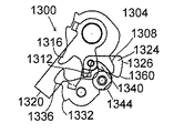
[シフト制御装置の別の実施形態]
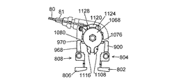
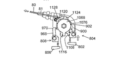
図21は、補助機構14と併用可能なシフト制御装置800の別の実施形態を示す詳細な図であり、図22は、シフト制御装置800の分解図である。この実施形態において、シフト制御装置800は、ブレーキレバーブラケット94の内側に隣接してハンドルバー50に取付けられている。シフト制御装置800は、周知の方法でネジ824によりシフト制御装置800をハンドルバー50にクランプするための一体形成型クランプバンド820を含む基部部材816などの取付ユニットを含む。ネジ型調節式コントロールケーブル連結器828が、基部部材816のフランジ部分832内にねじ込まれており、これに、コントロールケーブル82のアウターケーシング81を従来通りの方法で収容することができるようになっている。一般に、作動部材804の指接触部分802を押すとコントロールケーブル82のインナーワイヤ80が解除され、作動部材808の指接触部分806を押すとコントロールケーブル82のインナーワイヤ80が引っ張られる。その時点で選択されているギアは、ギアインジケータユニット812で示される。
[Another Embodiment of Shift Control Device]
FIG. 21 is a detailed view showing another embodiment of the shift control device 800 that can be used together with the auxiliary mechanism 14, and FIG. 22 is an exploded view of the shift control device 800. In this embodiment, the shift control device 800 is mounted on the handlebar 50 adjacent to the inside of the brake lever bracket 94. Shift control 800 includes a mounting unit such as a base member 816 that includes an integrally formed clamp band 820 for clamping shift control 800 to handlebar 50 with screws 824 in a well-known manner. A threaded adjustable control cable coupler 828 is threaded into the flange portion 832 of the base member 816 so that the outer casing 81 of the control cable 82 can be accommodated in a conventional manner. I have. Generally, pressing the finger contact portion 802 of the operating member 804 releases the inner wire 80 of the control cable 82, and pressing the finger contact portion 806 of the operating member 808 pulls the inner wire 80 of the control cable 82. The gear currently selected is indicated by gear indicator unit 812.
基部部材816の下側には、側壁844及び848を有する作動部材支持部836がネジ840により取付けられている。この側壁844に、支持部852、作動部材ガイド856、支持部860、付勢支持部材プレート864、及び支持部868がネジ872(図22には1つのみを図示)により取付けられている。作動部材804は、指接触部分802から延出している細長部分876を含み、この部分に、作動部材804がハンドルバー50に略垂直な方向で図21に示す定位置などの第1の作動部材位置と図24Dに示す最も内側に押された位置などの第2の作動部材位置との間で移動(例えば摺動)するように、作動部材ガイド856を取り囲む開口880が設けられている。爪支持基部884が、細長部分876の遠位端から横方向に延出し、爪軸888が、爪支持基部884から上方に延出している。バネ892が、作動部材804を定位置に向けて付勢するように、付勢支持プレート864の突起部896と爪支持基部884との間で接続されている。作動部材当接部(例えば、歯)902を含む爪900などの作動部材駆動部材が、爪軸888により回動自在に支持されて、爪支持基部884と爪900との間に取付けられた爪バネ904などの駆動部材付勢機構により時計回り方向に付勢されている。爪900は、クリップ908及びワッシャ912により、爪支持部シャフト888に固定されている。
An operating member support 836 having side walls 844 and 848 is attached to the lower side of the base member 816 by screws 840. A support portion 852, an operating member guide 856, a support portion 860, a biasing support member plate 864, and a support portion 868 are attached to the side wall 844 by screws 872 (only one is shown in FIG. 22). Actuating member 804 includes an elongated portion 876 extending from finger contacting portion 802, in which first actuating member 804 is positioned in a direction substantially perpendicular to handlebar 50, such as the home position shown in FIG. An opening 880 surrounding the actuating member guide 856 is provided to move (eg, slide) between the position and a second actuating member position, such as the innermost pushed position shown in FIG. 24D. A claw support base 884 extends laterally from the distal end of the elongated portion 876, and a claw shaft 888 extends upwardly from the claw support base 884. A spring 892 is connected between the projection 896 of the biasing support plate 864 and the claw support base 884 so as to bias the operating member 804 toward a fixed position. An operating member driving member such as a claw 900 including an operating member contact portion (for example, a tooth) 902 is rotatably supported by a claw shaft 888, and is attached between the claw support base 884 and the claw 900. It is urged clockwise by a driving member urging mechanism such as a spring 904. The claw 900 is fixed to the claw support shaft 888 by a clip 908 and a washer 912.
同様に、側壁848に、支持部920、作動部材ガイド924、支持部928、付勢支持部材プレート932、及び支持部936がネジ940(図22には1つのみを図示)により取り付けられている。作動部材808は、指接触部分806から延出している細長部分944を含み、この部分に、作動部材808がハンドルバー50に略垂直な方向で図21に示す定位置などの第1の作動部材位置と最も内側に押された位置などの第2の作動部材位置との間で移動(例えば摺動)するように、作動部材ガイド924を取り囲む開口948が設けられている。爪支持基部952が、細長部分944の遠位端から横方向に延出し、爪軸956が、爪支持基部952から上方に延出している。バネ960が、作動部材808を定位置に向けて付勢するように、付勢支持プレート932の突起部964と爪支持基部952との間に設けられている。作動部材当接部(例えば、歯)970を含む爪968などの作動部材駆動部材が、爪軸956により回動自在に支持されて、爪支持基部952と爪968との間に取付けられた爪バネ972などの駆動部材付勢機構により反時計回り方向に付勢されている。爪968は、クリップ976及びワッシャ980により、爪支持部シャフト956に固定されている。
Similarly, a support 920, an operating member guide 924, a support 928, a biasing support member plate 932, and a support 936 are attached to the side wall 848 by screws 940 (only one is shown in FIG. 22). . Actuating member 808 includes an elongate portion 944 extending from finger contacting portion 806, wherein actuating member 808 includes a first actuating member, such as the home position shown in FIG. An opening 948 surrounding the actuating member guide 924 is provided to move (eg, slide) between the position and a second actuating member position, such as a most inwardly pushed position. A claw support base 952 extends laterally from the distal end of the elongated portion 944, and a claw shaft 956 extends upwardly from the claw support base 952. A spring 960 is provided between the projection 964 of the biasing support plate 932 and the claw support base 952 so as to bias the operating member 808 toward a fixed position. An operating member driving member such as a claw 968 including an operating member abutting portion (for example, a tooth) 970 is rotatably supported by a claw shaft 956, and is attached between the claw support base 952 and the claw 968. It is urged in a counterclockwise direction by a driving member urging mechanism such as a spring 972. The claw 968 is fixed to the claw support shaft 956 by a clip 976 and a washer 980.
ボルト984は、そのヘッド996の高さが基部部材816の上面と実質的に同じになるように、基部部材816の開口988内及び作動部材支持部836の開口992内に延在している。ボルト984はさらに、ワイヤ巻取部材1008などのケーブル取付部材の中央開口1004内に嵌合するブシュ1000内、解除プレート1016の開口1012内、ワッシャ1020、1028及びスペーサ1024内、付勢プレート1036の中央開口1032内、スペーサ1040及びワッシャ1044内、半径方向に巻かれたバネ1048の内側、付勢プレート1056の中央開口1052内、ワッシャ1060、及び付勢止めプレート1068の中央開口1064内に延出する。これらの部材は、ボルト984のネジ切り端部1074に螺合するナット1072により、ボルト984に固定されている。
Bolt 984 extends within opening 988 of base member 816 and opening 992 of actuation member support 836 such that the height of head 996 is substantially the same as the top surface of base member 816. Bolts 984 are also provided within bushing 1000 that fits into central opening 1004 of a cable mounting member, such as wire take-up member 1008, within opening 1012 of release plate 1016, within washers 1020, 1028 and spacer 1024, and within biasing plate 1036. Extends within central opening 1032, within spacer 1040 and washer 1044, inside radially wound spring 1048, within central opening 1052 of biasing plate 1056, within central opening 1064 of washer 1060, and biasing stop plate 1068. I do. These members are fixed to the bolt 984 by a nut 1072 screwed to the threaded end 1074 of the bolt 984.
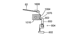
ワイヤ巻取部材1008は、当接部または制御面1076及び1080などの被駆動部と、下向きに延出する付勢係合部材1120と、コントロールケーブル82のインナーワイヤ80を巻取り、解除するためのワイヤ巻取り溝1122とを含む。解除プレート1016が、基部部材816にネジ1090で固定されており、これが、カム面1084及び1088などの解除部材を含む。上述した部材の機能を、以下に記載する。
The wire winding member 1008 is for winding and releasing the driven portion such as the contact portion or the control surfaces 1076 and 1080, the biasing engagement member 1120 extending downward, and the inner wire 80 of the control cable 82. And a wire winding groove 1122. A release plate 1016 is secured to the base member 816 with screws 1090, which includes release members such as cam surfaces 1084 and 1088. The functions of the above-described members will be described below.
付勢プレート1036は、半径方向外向きに延出するストッパ1116と、半径方向外向きに延出するワイヤ巻取り部材付勢部材1124とを含む。同様に、付勢プレート1056は、半径方向外向きに延出するストッパ1108と、半径方向外向きに延出するワイヤ巻取り部材付勢部材1128とを含む。バネ1048の一方の端部1092が、付勢プレート1056に周方向に設けられた複数開口1096の1つの内部に挿入され、バネ1048のもう一方の端部1100が付勢プレート1056のストッパ1108を係合する。このような構成により、付勢プレート1036は時計方向に付勢されて、ストッパ1116が、付勢止めプレート1068から上方に延出する折り曲げ部1112に当接し、付勢プレート1056は反時計方向に付勢されて、ストッパ1108が折り曲げ部1112に当接する。したがって、付勢プレート1036及び1056とバネ1048とが、操作機構が停止状態にある間、ケーブル取付部材を第1のケーブル取付部材位置に固定するケーブル取付部材初期位置位置決め機構として機能する。ワイヤ巻取部材1008の付勢係合部材1120が、第1のケーブル取付部材位置(例えば、定位置または初期位置)において、ワイヤ巻取部材付勢部材1124と1128との間に挟持される。ワイヤ巻取部材1008が、第2のケーブル取付部材位置(例えば、ワイヤ引上げ位置)に向けて反時計回り方向に第1の経路に沿って回転すると、バネ1048及び付勢プレート1036が、ワイヤ巻取部材1008を第1のケーブル取付部材位置に向けて時計回りに付勢して戻すケーブル取付部材付勢機構として機能する。同様に、ワイヤ巻取部材1008が、第3のケーブル取付部材位置(例えば、ワイヤ解除位置)に向けて時計回り方向に第2の経路に沿って回転すると、バネ1048及び付勢プレート1056が、ワイヤ巻取部材1008を第1のケーブル取付部材位置に向けて反時計回りに付勢して戻すケーブル取付部材付勢機構として機能する。言い換えれば、付勢プレート1036、1056及びバネ1048は、操作機構が停止状態にある間、ワイヤ巻取部材1008を第1のケーブル取付部材位置に固定するワイヤ巻取部材初期位置位置決め機構としても機能する。
The urging plate 1036 includes a stopper 1116 extending radially outward, and a wire winding member urging member 1124 extending radially outward. Similarly, the biasing plate 1056 includes a stopper 1108 extending radially outward and a wire winding member biasing member 1128 extending radially outward. One end 1092 of the spring 1048 is inserted into one of a plurality of openings 1096 provided in the biasing plate 1056 in the circumferential direction, and the other end 1100 of the spring 1048 engages the stopper 1108 of the biasing plate 1056. Engage. With such a configuration, the urging plate 1036 is urged clockwise, the stopper 1116 comes into contact with the bent portion 1112 extending upward from the urging stop plate 1068, and the urging plate 1056 moves counterclockwise. When urged, the stopper 1108 comes into contact with the bent portion 1112. Therefore, the urging plates 1036 and 1056 and the spring 1048 function as a cable attachment member initial position positioning mechanism for fixing the cable attachment member at the first cable attachment member position while the operation mechanism is stopped. The biasing engagement member 1120 of the wire winding member 1008 is sandwiched between the wire winding member biasing members 1124 and 1128 at a first cable attachment member position (for example, a fixed position or an initial position). When the wire take-up member 1008 rotates along the first path in a counterclockwise direction toward a second cable attachment member position (e.g., a wire pull-up position), the spring 1048 and the biasing plate 1036 cause the wire take-up member to rotate. It functions as a cable attachment member urging mechanism that urges the return member 1008 clockwise toward the first cable attachment member position and returns it. Similarly, when the wire take-up member 1008 rotates along the second path in a clockwise direction toward a third cable attachment member position (eg, a wire release position), the spring 1048 and the biasing plate 1056 are rotated. The wire winding member 1008 functions as a cable attachment member urging mechanism that is urged counterclockwise to return to the first cable attachment member position. In other words, the urging plates 1036, 1056 and the spring 1048 also function as a wire winding member initial position positioning mechanism for fixing the wire winding member 1008 to the first cable attachment member position while the operation mechanism is stopped. I do.
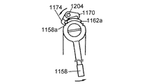
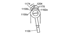
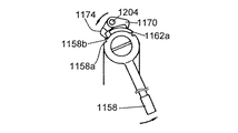
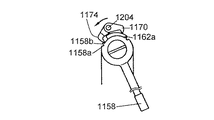
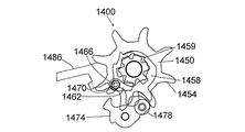
[ギアインジケータユニット]
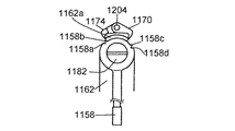
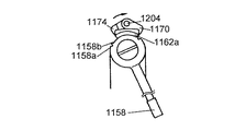
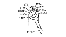
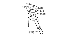
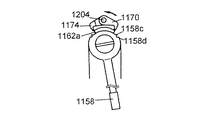
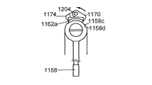
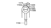
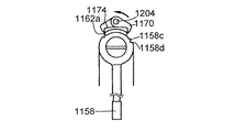
ギアインジケータユニット812は、透明な窓1154を備えたカバー1150(図21)と、インジケータ1158と、爪支持プレート1162と、伝動部材1166と、爪1170及び1174などのインジケータ駆動部材と、付勢バネ1178とを含む。インジケータ1158は、ネジ1182及びワッシャ1186でボルト984のヘッド996に回転自在に取付けられている。図25Aに詳細に示すように、インジケータ1158は、爪歯1158a、1158b、1158c及び1158dなどのインジケータ被駆動部材を含む。爪支持プレート1162も、ネジ1182によりボルト984のヘッド996に取付けられており、基部部材816の突起部1194に爪支持プレート1162の突起部1190が係合する構造により、基部部材816に回転できない状態で固定されている。爪支持プレート1162は、以下に説明するように機能する爪非係合面1162aを含む。
[Gear indicator unit]
The gear indicator unit 812 includes a cover 1150 (FIG. 21) with a transparent window 1154, an indicator 1158, a pawl support plate 1162, a transmission member 1166, an indicator drive member such as pawls 1170 and 1174, and a biasing spring. 1178. The indicator 1158 is rotatably attached to the head 996 of the bolt 984 with a screw 1182 and a washer 1186. As shown in detail in FIG. 25A, indicator 1158 includes indicator driven members such as pawl teeth 1158a, 1158b, 1158c and 1158d. The claw support plate 1162 is also attached to the head 996 of the bolt 984 by a screw 1182, and cannot be rotated by the base member 816 due to the structure in which the protrusion 1190 of the claw support plate 1162 is engaged with the protrusion 1194 of the base member 816. It is fixed at. The pawl support plate 1162 includes a pawl non-engaging surface 1162a that functions as described below.
伝動部材1166は、ワイヤ巻取部材1008に形成された開口1200に係合する1対のタブ1198により、ワイヤ巻取部材1008に連結されている。これにより、伝動部材1166はユニットとして、ワイヤ巻取部材1008と共に移動する。伝動部材1166はまた、爪1170及び1174を回動自在に支持するように、爪軸1204を含む。これにより各爪は、インジケータ被駆動部材係合位置とインジケータ被駆動部材非係合位置との間を移動できるようになっている。バネ1178の一端部1230が、爪1170と係合して、爪1170をその対応インジケータ被駆動部材係合位置方向に付勢する付勢機構として機能する。同様に、バネ1178の一端部1234が、爪1174と係合して、爪1174をその対応インジケータ被駆動部材係合位置に向けて付勢する付勢機構として機能する。爪1170及び1174とバネ1178とは、クリップ1208により爪軸1204に固定されている。
The transmission member 1166 is connected to the wire winding member 1008 by a pair of tabs 1198 that engage with openings 1200 formed in the wire winding member 1008. Thus, the transmission member 1166 moves together with the wire winding member 1008 as a unit. The transmission member 1166 also includes a pawl shaft 1204 to rotatably support the pawls 1170 and 1174. Thereby, each claw can move between the indicator driven member engaging position and the indicator driven member non-engaging position. One end 1230 of the spring 1178 is engaged with the pawl 1170, and functions as a biasing mechanism for biasing the pawl 1170 toward its corresponding indicator driven member engaging position. Similarly, one end 1234 of the spring 1178 engages the pawl 1174 and functions as a biasing mechanism for biasing the pawl 1174 toward its corresponding indicator driven member engagement position. The pawls 1170 and 1174 and the spring 1178 are fixed to the pawl shaft 1204 by clips 1208.
[シフト制御装置の動作:ワイヤ巻取方向]
図23A〜図23B及び図24A〜図24Dは、図23A及び図24Aに示す作動部材804が第1のシフト制御(オペレータアタッチメント)位置から図24Dに示す第3のシフト制御(オペレータアタッチメント)位置まで移動する間のシフト制御装置800の操作を示している(底部から180°回転させて見たところ)。まず作動部材804の指接触部分802を押すと、爪歯902がカム面1084に沿って移動する。次に、バネ904の付勢力とカム面1084の形状とにより、爪900が反時計回りに回転すると、図24Bに示すように、爪歯902がワイヤ巻取部材1008の当接部1076を係合(例えば、接触)する。さらに指接触部分802を押すと、図24Cに示すように、ワイヤ巻取部材1008が反時計回りに回転して、インナーワイヤ80を解除し、補助機構14が上述したように動作する。したがって、作動部材804及び爪900を、ワイヤ巻取部材1008を第1のケーブル取付部材位置から第3のケーブル取付部材位置に向けて動作させる操作機構の一部と見なすことができる。同時に、付勢係合部材1120が、付勢プレート1056のワイヤ巻取部材付勢部材1128を図23Bに示すように押付けられて、付勢プレート1056をバネ1048の付勢力に抗して反時計回りに回転させる。さらに指接触部分802を押すことにより、カム面1084の形状の影響で、爪900が時計回りに回転して、図24Dに示すように、爪歯902がワイヤ巻取部材1008の当接部1076から外れる。このように外れると、バネ1048の付勢力により、ワイヤ巻取部材1008及び付勢プレート1056は、図23A及び図24Aに示す位置まで反時計回りに回転して戻る。爪歯902が当接部1076から外れることにより、指接触部材802にはクリック感が伝わるため、乗り手は指接触部材806を放してよいことがわかる。
[Operation of shift control device: wire winding direction]
FIGS. 23A to 23B and FIGS. 24A to 24D show that the operating member 804 shown in FIGS. 23A and 24A moves from the first shift control (operator attachment) position to the third shift control (operator attachment) position shown in FIG. 24D. The operation of the shift control device 800 during the movement is shown (as viewed by rotating it 180 ° from the bottom). First, when the finger contact portion 802 of the operating member 804 is pressed, the pawl teeth 902 move along the cam surface 1084. Next, when the pawl 900 rotates counterclockwise due to the urging force of the spring 904 and the shape of the cam surface 1084, the pawl teeth 902 engage the contact portion 1076 of the wire winding member 1008 as shown in FIG. 24B. Contact (eg, contact). When the finger contact portion 802 is further pressed, as shown in FIG. 24C, the wire winding member 1008 rotates counterclockwise to release the inner wire 80, and the auxiliary mechanism 14 operates as described above. Therefore, the operating member 804 and the claw 900 can be regarded as a part of an operating mechanism that operates the wire winding member 1008 from the first cable mounting member position to the third cable mounting member position. At the same time, the urging engagement member 1120 presses the wire take-up member urging member 1128 of the urging plate 1056 as shown in FIG. 23B, and pushes the urging plate 1056 against the urging force of the spring 1048 in a counterclockwise direction. Rotate around. Further pressing of the finger contact portion 802 causes the claw 900 to rotate clockwise under the influence of the shape of the cam surface 1084, thereby causing the claw teeth 902 to abut on the contact portion 1076 of the wire winding member 1008 as shown in FIG. 24D. Get off. When disengaged in this way, the urging force of the spring 1048 causes the wire winding member 1008 and the urging plate 1056 to rotate counterclockwise back to the positions shown in FIGS. 23A and 24A. Since the click feeling is transmitted to the finger contact member 802 when the claw teeth 902 are disengaged from the contact portion 1076, it is understood that the rider may release the finger contact member 806.
シフト制御装置800は、作動部材808の指接触部材806が図23Cに示すように押された場合も同様に動作する。この場合、爪歯970はワイヤ巻取部材1008の当接部1080に係合して、ワイヤ巻取部材1008を第1のシフト制御(オペレータアタッチメント)位置から時計回りにワイヤ引上げ方向に第2のシフト制御(オペレータアタッチメント)位置まで回転させるため、これに伴って補助機構14が動作する。したがって、作動部材806及び爪968を、ワイヤ巻取部材1008を第1のケーブル取付部材位置から第2のケーブル取付部材位置まで動作させる操作機構のもう1つの一部と見なすことができる。同時に、付勢係合部材1120が、図23Cに示すように、付勢プレート1036のワイヤ巻取部材付勢部材1124に押付けられて、付勢プレート1036をバネ1048の付勢力に抗して時計回りに回転させる。さらに指接触部分806を押すことにより、カム面1088の形状の影響で、爪968が反時計回りに回転して、爪歯970がワイヤ巻取部材1008の当接部1088から外れる。爪968が外れた時点で、バネ1048の付勢力により、ワイヤ巻取部材1008及び付勢プレート1036は反時計回りに回転して図23Aに示す位置に戻る。爪歯970が当接部1088から外れることにより、指接触部材806に同様にクリック感が伝わるため、乗り手は指接触部材806を放してよいことがわかる。
Shift control device 800 operates similarly when finger contact member 806 of actuating member 808 is pressed as shown in FIG. 23C. In this case, the pawl teeth 970 are engaged with the abutting portions 1080 of the wire winding member 1008 to move the wire winding member 1008 clockwise from the first shift control (operator attachment) position to the second position in the wire pulling direction. In order to rotate to the shift control (operator attachment) position, the auxiliary mechanism 14 operates accordingly. Therefore, the operating member 806 and the claw 968 can be regarded as another part of the operating mechanism that moves the wire winding member 1008 from the first cable attachment member position to the second cable attachment member position. At the same time, the urging engagement member 1120 is pressed against the wire winding member urging member 1124 of the urging plate 1036 as shown in FIG. 23C, and the urging plate 1036 is pressed against the urging force of the spring 1048. Rotate around. By further pressing the finger contact portion 806, the pawl 968 rotates counterclockwise due to the shape of the cam surface 1088, and the pawl 970 is disengaged from the contact portion 1088 of the wire winding member 1008. When the claw 968 comes off, the wire take-up member 1008 and the urging plate 1036 rotate counterclockwise by the urging force of the spring 1048 and return to the position shown in FIG. 23A. Since the click feeling is similarly transmitted to the finger contact member 806 when the claw teeth 970 are disengaged from the contact portion 1088, it is understood that the rider may release the finger contact member 806.
[インジケータの動作]
シフト制御装置800がワイヤ引上げ方向に動作した時点におけるインジケータユニット812の動作(上から見たところ)を、図25A〜図25Iに示す。図25Aは、インジケータ1158が定位置にある状態を示している。同時に、ワイヤ巻取部材1008は第1のケーブル取付部材位置にあり、爪1170及び1174は爪解除面1162aにより支持されている。作動部材808の指接触面806が押された結果としてワイヤ巻取部材1008が反時計回りに回転すると、伝動部材1166が爪1170及び1174を図25Bに示す位置に移動させるため、爪1174が爪歯1158aに接触する。ワイヤ巻取部材1008がさらに回転することにより、爪1174が爪歯1158aに押付けられて、インジケータ1158を図25Cに示す位置まで回転させる。爪歯970が当接部1080から外れ、ワイヤ巻取部材1008が時計回りに第1のケーブル取付部材位置に向けて回転しながら戻ると、伝動部材1166により、爪1174は爪歯1158aから外れ、爪1170及び1174は図25Dに示す位置まで回転する。このとき、爪1170及び1174は、爪解除面1162aに支持される。このように、ワイヤ巻取部材1008がその元の位置まで回転しながら戻っていても、インジケータ1158は、新たに選択されたギアを反映する。
[Operation of indicator]
FIGS. 25A to 25I show the operation (as viewed from above) of indicator unit 812 when shift control device 800 operates in the wire pulling direction. FIG. 25A shows a state where the indicator 1158 is at a fixed position. At the same time, the wire take-up member 1008 is at the first cable attachment member position, and the pawls 1170 and 1174 are supported by the pawl release surface 1162a. When the wire take-up member 1008 rotates counterclockwise as a result of the finger contact surface 806 of the actuating member 808 being pressed, the pawl 1174 is moved by the transmission member 1166 to move the pawls 1170 and 1174 to the positions shown in FIG. 25B. It contacts the teeth 1158a. As the wire take-up member 1008 further rotates, the pawl 1174 is pressed against the pawl 1158a, and rotates the indicator 1158 to the position shown in FIG. 25C. When the claw teeth 970 are disengaged from the abutting portion 1080 and the wire winding member 1008 is rotated clockwise toward the first cable attachment member position, the claw 1174 is disengaged from the claw teeth 1158a by the transmission member 1166, The claws 1170 and 1174 rotate to the position shown in FIG. 25D. At this time, the claws 1170 and 1174 are supported by the claw release surface 1162a. Thus, even though wire winding member 1008 is rotating back to its original position, indicator 1158 reflects the newly selected gear.
作動部材808の指接触面806が2回目に押された結果としてワイヤ巻取部材1008が反時計回りに回転すると、伝動部材1166が爪1170及び1174を図25Eに示す位置まで移動させるため、爪1174が爪歯1158bに接触する。ワイヤ巻取部材1008がさらに回転することにより、爪1174が爪歯1158bに押付けられて、インジケータ1158を図25Fに示す位置まで回転させる。爪歯970が当接部1080から外れ、ワイヤ巻取部材1008が時計回りに第1のケーブル取付部材位置に向けて回転しながら戻ると、伝動部材1166により、爪1174が爪歯1158bから外れ、爪1170及び1174は図25Gに示す位置まで回転しながら戻る。こうして、爪1170及び1174は爪支持部材1162aに支持され、インジケータ1158は、最終的に選択されたギアを反映する状態となる。
When the wire take-up member 1008 rotates counterclockwise as a result of the finger contact surface 806 of the actuating member 808 being pressed a second time, the transmission member 1166 moves the pawls 1170 and 1174 to the position shown in FIG. 1174 contacts the claw teeth 1158b. When the wire winding member 1008 further rotates, the claw 1174 is pressed against the claw teeth 1158b, and the indicator 1158 is rotated to the position shown in FIG. 25F. When the claw teeth 970 are disengaged from the contact portion 1080 and the wire winding member 1008 is rotated clockwise toward the first cable attachment member position and returned, the transmission member 1166 causes the claw 1174 to be disengaged from the claw teeth 1158b. The claws 1170 and 1174 return while rotating to the position shown in FIG. 25G. Thus, the pawls 1170 and 1174 are supported by the pawl support member 1162a, and the indicator 1158 is in a state reflecting the finally selected gear.
この実施形態において、補助機構14は3枚のフロントギアを収容する。乗り手が、ディレーラがすでに最終ギア位置にあることを忘れて、指接触部材806を再度押した場合、ワイヤ巻取部材1008が再度反時計回りに回転し、伝動部材1166が爪1170及び1174を図25Hに示す位置に移動させる。しかし、この場合は爪歯が係合しないため、インジケータ1158は同じ位置に留まる。続いて、ワイヤ巻取部材1008が第1のケーブル取付部材位置に回転しながら戻り、爪1170及び1174は再度爪解除面1162aに支持される。無論、爪歯の数を増減すれば、所望に応じてギアの数を増減することができる。
In this embodiment, the auxiliary mechanism 14 accommodates three front gears. If the rider forgets that the derailleur is already in the final gear position and presses the finger contact member 806 again, the wire take-up member 1008 will again rotate counterclockwise and the transmission member 1166 will see the pawls 1170 and 1174. Move to the position shown at 25H. However, in this case, since the pawl teeth do not engage, the indicator 1158 remains in the same position. Subsequently, the wire winding member 1008 returns while rotating to the first cable attachment member position, and the claws 1170 and 1174 are again supported by the claw release surface 1162a. Of course, if the number of claw teeth is increased or decreased, the number of gears can be increased or decreased as desired.
[シフト制御装置の動作:ワイヤ解除方向]
シフト制御装置800が反対(ワイヤ解除)方向に動作した時点におけるインジケータユニット812の動作を、図26A〜図26Iに示す。図26Aは、インジケータ1158が図25Hの位置と同じ位置にあることを示している。すなわち、ワイヤ巻取部材1008は第1のケーブル取付部材位置にあり、爪1170及び1174は爪解除面1162aに支持されている。作動部材804の指接触面802が押されて、ワイヤ巻取部材1008が時計回りに回転すると、伝動部材1166が爪1170及び1174を図26Bに示す位置まで移動させるため、爪1170が爪歯1158dに接触する。ワイヤ巻取部材1008がさらに回転すると、爪1170が爪歯1158dに押付けられて、インジケータ1158を図26Cに示す位置まで回転させる。爪歯902が当接部1076から外れて、ワイヤ巻取部材1008が時計回りに第1のケーブル取付部材位置に向けて回転しながら戻ると、伝動部材1166により、爪1170は爪歯1158dから外れ、爪1170及び1174は図26(D)に示す位置まで回転しながら戻る。こうして、爪1170及び1174は、爪解除面1162aに支持された状態となる。
[Operation of shift control device: wire release direction]
26A to 26I show the operation of the indicator unit 812 when the shift control device 800 operates in the opposite (wire release) direction. FIG. 26A shows that indicator 1158 is in the same position as in FIG. 25H. That is, the wire take-up member 1008 is at the position of the first cable attachment member, and the claws 1170 and 1174 are supported by the claw release surface 1162a. When the finger contact surface 802 of the operating member 804 is pressed and the wire winding member 1008 rotates clockwise, the transmission member 1166 moves the claws 1170 and 1174 to the position shown in FIG. Contact When the wire winding member 1008 further rotates, the claw 1170 is pressed against the claw teeth 1158d, and rotates the indicator 1158 to the position shown in FIG. 26C. When the pawl teeth 902 are disengaged from the contact portion 1076 and the wire winding member 1008 is rotated clockwise toward the first cable attaching member position and returned, the pawl 1170 is disengaged from the pawl teeth 1158d by the transmission member 1166. The claws 1170 and 1174 return while rotating to the position shown in FIG. Thus, the claws 1170 and 1174 are in a state of being supported by the claw release surface 1162a.
作動部材804の指接触面802が2回目に押された結果としてワイヤ巻取部材1008が時計回りに回転すると、伝動部材1166が爪1170及び1174を図26Eに示す位置まで移動させるため、爪1170が爪歯1158cに接触する。ワイヤ巻取部材1008がさらに回転することにより、爪1170が爪歯1158cに押付けられて、インジケータ1158を図26Fに示す位置まで回転させる。爪歯902が当接部1080から外れ、ワイヤ巻取部材1008が反時計回りに第1のケーブル取付部材位置に向けて回転しながら戻ると、伝動部材1166により、爪1170は爪歯1158cから外れ、爪1170及び1174は図26Gに示す位置まで回転する。こうして、爪1170及び1174は、爪解除面1162aに支持され、インジケータ1158は、その元の位置に戻った状態となる。
When the wire take-up member 1008 rotates clockwise as a result of the finger contact surface 802 of the actuating member 804 being pressed a second time, the transmission member 1166 moves the pawls 1170 and 1174 to the position shown in FIG. Contacts the claw teeth 1158c. When the wire winding member 1008 further rotates, the claw 1170 is pressed against the claw teeth 1158c, and the indicator 1158 is rotated to the position shown in FIG. 26F. When the pawl teeth 902 are disengaged from the abutting portion 1080 and the wire winding member 1008 returns while rotating counterclockwise toward the first cable attachment member position, the pawl 1170 is disengaged from the pawl teeth 1158c by the transmission member 1166. , The pawls 1170 and 1174 rotate to the position shown in FIG. 26G. Thus, the pawls 1170 and 1174 are supported by the pawl release surface 1162a, and the indicator 1158 returns to its original position.
この場合もまた、乗り手が、ディレーラがすでに最終ギア位置にあることを忘れて、指接触部材806を再度押した場合、ワイヤ巻取部材1008は再度時計回りに回転し、伝動部材1166は爪1170及び1174を図26Hに示す位置に移動させる。しかし、爪歯が係合しないため、インジケータ1158は同じ位置に留まり、ワイヤ巻取部材1008が第1のケーブル取付部材位置に回転しながら戻り、爪1170及び1174は再度爪解除面1162aに支持された状態となる。
Again, if the rider forgets that the derailleur is already in the final gear position and presses the finger contact member 806 again, the wire take-up member 1008 will again rotate clockwise and the transmission member 1166 will engage the pawl 1170 And 1174 are moved to the positions shown in FIG. 26H. However, because the pawl teeth do not engage, the indicator 1158 remains in the same position, the wire take-up member 1008 rotates back to the first cable mounting member position, and the pawls 1170 and 1174 are again supported by the pawl release surface 1162a. State.
[シフトレバー機構]
開示した実施形態のさまざまな教示内容を、別の環境に適用することができる。たとえば、図27(A)〜図27(H)は、図17(A)〜図17(F)に示した解除機構の構造及び動作のいくつかを組み入れたシフトレバー機構1300を示すものである。シフトレバー機構1300は通常、支持部材に取付けられ、かつ/または筐体内に配置される。しかし、これらの図面では、この実施形態を理解し易くするために、構造のみを図示している。
[Shift lever mechanism]
The various teachings of the disclosed embodiments can be applied to other environments. For example, FIGS. 27A to 27H show a shift lever mechanism 1300 that incorporates some of the structures and operations of the release mechanism shown in FIGS. 17A to 17F. . Shift lever mechanism 1300 is typically mounted on a support member and / or located within a housing. However, in these drawings, only the structure is illustrated in order to facilitate understanding of this embodiment.
図27(A)に示すように、シフトレバー機構1300は、位置決めラチェット1304の形態である位置決め部材と、位置保持部材1332と、シフトレバー1320の形態である解除部材と、カムプレート1324の形態であるカム部材とを含む。位置決めラチェット1304は、回転部材(図示していないが、図10の回転部材454に類似したもの)と同軸状に一体となって回転するように回転軸1333に連結されており、位置決め歯1308、1312及び1316を具備している。位置決めラチェット1304及びこれに付随する回転部材は、戻しバネ(図示していないが、図10のバネ456に類似したもの)により時計回り方向に付勢されている。位置保持部材1332は、位置保持位置(例えば図27(A)に示す位置)と位置解除位置(例えば図27(D)に示す位置)との間で回転できるように、爪軸1334に支持された位置決め爪の形態であり、位置決め爪1332は、位置決め歯1336及び1340と、位置決め歯1340に取付けられた回動軸1342と、回動軸1342に回転自在に支持されたカムローラ1344の形態であるカムフォロアとを有する。この位置決め爪1332を位置保持位置に向けて反時計回りに付勢するように、爪バネ(図示せず)が設けられている。シフトレバー1320(通常、ワイヤ解除方向にシフト機構を動作させるために使用するもの)は、回転軸1333を中心として回転自在に支持されており、カムプレート1324を支持する回動軸1328を有する。第1の実施形態の場合と同様に、カムプレート1324全体の形状は丸みを帯びた細長い二等辺三角形である。このカムプレート1324は、バネ(図示せず)により時計回り方向に付勢されているため、シフトレバー1320の側部面1354にぶつかってカムプレート1324を図27(A)に示す位置に保持するための、半径方向に延出した位置決めタブ1350を具備している。
As shown in FIG. 27A, a shift lever mechanism 1300 includes a positioning member in the form of a positioning ratchet 1304, a position holding member 1332, a release member in the form of a shift lever 1320, and a cam plate 1324. A certain cam member. The positioning ratchet 1304 is connected to the rotating shaft 1333 so as to rotate coaxially and integrally with a rotating member (not shown, but similar to the rotating member 454 in FIG. 10), and the positioning teeth 1308, 1312 and 1316 are provided. The positioning ratchet 1304 and its associated rotating member are biased clockwise by a return spring (not shown, but similar to the spring 456 of FIG. 10). The position holding member 1332 is supported by the claw shaft 1334 so as to be rotatable between a position holding position (for example, a position shown in FIG. 27A) and a position release position (for example, a position shown in FIG. 27D). The positioning claw 1332 is in the form of positioning teeth 1336 and 1340, a rotating shaft 1342 attached to the positioning teeth 1340, and a cam roller 1344 rotatably supported by the rotating shaft 1342. And a cam follower. A claw spring (not shown) is provided to bias the positioning claw 1332 counterclockwise toward the position holding position. The shift lever 1320 (usually used for operating the shift mechanism in the wire releasing direction) is rotatably supported around a rotation shaft 1333, and has a rotation shaft 1328 that supports a cam plate 1324. As in the case of the first embodiment, the overall shape of the cam plate 1324 is a rounded elongated isosceles triangle. Since the cam plate 1324 is urged clockwise by a spring (not shown), the cam plate 1324 hits the side surface 1354 of the shift lever 1320 and holds the cam plate 1324 at the position shown in FIG. A radially extending locating tab 1350 for positioning.
乗り手がシフトレバー1320を図27(A)に示す定位置または第1の解除部材位置から反時計回りに回転させると、図27(B)に示すように、カムプレート1324の基部面1326がまずカムローラ1344に接触する。さらにシフトレバー1320が回転することにより、カムプレート1324がカムローラ1344に押付けられるため、図27(C)に示すように、位置決め爪1332が時計回り方向に回転する。爪歯1340の先端が位置決め歯1312の先端を通過すると、図27(D)に示すように、位置決め歯1316が爪歯1336にぶつかって位置決めラチェット1304及びこれに付随する回転部材の非制御回転を阻止するまで、位置決めラチェット1304(及びこれに付随する回転部材)が戻しバネの付勢力にしたがって時計回り方向に回転する。
When the rider rotates the shift lever 1320 counterclockwise from the home position or the first release member position shown in FIG. 27 (A), the base surface 1326 of the cam plate 1324 firstly moves as shown in FIG. 27 (B). It contacts the cam roller 1344. When the shift lever 1320 further rotates, the cam plate 1324 is pressed against the cam roller 1344, so that the positioning claw 1332 rotates clockwise as shown in FIG. 27C. When the tip of the claw tooth 1340 passes through the tip of the positioning tooth 1312, as shown in FIG. 27 (D), the positioning tooth 1316 hits the claw tooth 1336, and the uncontrolled rotation of the positioning ratchet 1304 and the rotating member attached thereto is performed. Until this occurs, the positioning ratchet 1304 (and its associated rotating member) rotates clockwise in accordance with the biasing force of the return spring.
シフトレバー1320が第2の解除部材位置(例えば、図27(F)に示すシフトレバー1320の動作範囲終点)に向けて反時計回りに回転を続ける間、カムプレート1324の丸みを帯びた角部1360が図27(D)に示すように、カムローラ1344を通過するため、カムローラ1344によって、カムプレート1324は図27(E)に示すように反時計回り方向に回転する。これにより、位置決め爪1332が反時計回りに回転して、爪歯1336が位置決め歯1316から遠ざかる方向に移動し、爪歯1340が位置決め歯1308に係合する。こうして、位置決めラチェット1304及びこれに付随する回転部材は、自転車変速機を所望状態に固定するように位置決められる。この後、シフトレバー1320は、図27(G)及び図27(H)に示すように、第1の解除部材位置に復帰することができる。
While the shift lever 1320 continues to rotate counterclockwise toward the second release member position (eg, the end of the operating range of the shift lever 1320 shown in FIG. 27 (F)), the rounded corners of the cam plate 1324 27D, the cam plate 1324 is rotated counterclockwise by the cam roller 1344 as shown in FIG. 27E. As a result, the positioning claw 1332 rotates counterclockwise, the claw tooth 1336 moves in a direction away from the positioning tooth 1316, and the claw tooth 1340 engages with the positioning tooth 1308. Thus, positioning ratchet 1304 and its associated rotating member are positioned to secure the bicycle transmission in a desired state. Thereafter, the shift lever 1320 can return to the first release member position as shown in FIGS. 27 (G) and 27 (H).
シフト操作を制御するために位置決め爪及び位置決めラチェットを用いる周知のシステムにしたがってこのシステムを操作した場合、爪歯1340は、図27(F)に示すシフトレバー1320が動作範囲終点(第2の解除部材位置)に到達するまで、位置決め歯1312に係合した状態を続けることになる。また、位置決め爪1332は、シフトレバー1320が第1の解除部材位置に向けてある程度回転して戻るまで、爪歯1336が位置決め歯1316から遠ざかる方向に移動して爪歯1340が位置決め歯1308に係合するように反時計回り方向に回転することはない。本明細書に記載するシフト制御機構の場合、この動作は不要である。回転自在なカムプレート1324が設けられているため、シフトレバー1320が第1の解除位置に向けて戻り始める前に、シフトレバー1320がまだ反時計回り方向に回転している間にでさえ、位置決め爪1332が直ちにシフト操作を完了できるからである。さらに、カムプレート1324に類似のカムプレートが、連続してカムローラ1344に接触できるようにシフトレバー1320に追加して取付けられていれば、シフトレバー1320を図27(E)に示す位置から反時計回りにさらに回転させて、複数のシフトを実行することができる。
When operating this system according to a well-known system that uses positioning pawls and positioning ratchets to control the shifting operation, the pawl teeth 1340 will cause the shift lever 1320 shown in FIG. Until the position (member position) is reached, the state of engagement with the positioning teeth 1312 is continued. Further, the positioning claw 1332 moves in the direction in which the claw tooth 1336 moves away from the positioning tooth 1316 until the shift lever 1320 rotates to some extent toward the first release member position and returns, so that the claw tooth 1340 engages with the positioning tooth 1308. They do not rotate counterclockwise to match. This operation is not necessary for the shift control mechanism described herein. Because the rotatable cam plate 1324 is provided, the position is determined even before the shift lever 1320 is still rotating in a counterclockwise direction before the shift lever 1320 starts to return to the first release position. This is because the claw 1332 can immediately complete the shift operation. Furthermore, if a cam plate similar to the cam plate 1324 is additionally attached to the shift lever 1320 so that it can continuously contact the cam roller 1344, the shift lever 1320 is moved counterclockwise from the position shown in FIG. Multiple rotations can be performed by further rotation around.
[シフトレバーアセンブリ]
図28は、図20に示した実施形態の教示内容の幾つかを組み入れたシフトレバーアセンブリ1440を示す図である。図20に示した実施形態と同様に、カムホイール1450が、カムローラ1478を有する位置決め爪1474の操作を制御している。カムホイール1450は、位置決めラチェット1458に対して同軸状に回転自在に取付けられており、周方向に配置された複数のカム歯1454と、周方向に配置された複数のカム駆動歯1459とを具備している。カム駆動歯1462は、回動軸1466を介してシフトレバー1486に回動自在に取付けられ、バネ1470により反時計回りに付勢されている。シフトレバー1486が反時計回り方向(通常、ワイヤ解除方向)に回転すると、カム駆動爪1462は、カム駆動歯1459の1つに係合して、カムホイール1450を反時計回り方向に回転させる。すると、カム歯1454の1つがカムローラ1478に押付けられるため、位置決め爪1474が、図27(A)〜図27(D)に示す実施形態と同様に、反時計回り方向に回転する。カム歯1454がカムローラ1478を通過すると、位置決め爪1474が反時計回り方向に回転して、図27(E)に示した実施形態と同様に、シフト操作を完了する。シフトレバー1486が時計回りに回転すると、カム駆動爪1462が、これに対応するカム駆動歯1459から外れる。図27(A)〜図27(H)に示した実施形態と同様に、カムホイール1450にカム歯1454が設けられているため、シフトレバー1486が第1の解除位置に向けて戻り始める前に、また、シフトレバー1486がまだ反時計回り方向に回転している間にでさえ、位置決め爪1474は直ちにシフト操作を完了することができる。実際、シフトレバー1486をさらに反時計回りに回転させて、複数のカム歯1454を1つずつ連続的にカムローラ1478に押付けることにより、複数のシフトを実行することができる。
[Shift lever assembly]
FIG. 28 shows a shift lever assembly 1440 incorporating some of the teachings of the embodiment shown in FIG. As in the embodiment shown in FIG. 20, a cam wheel 1450 controls the operation of a positioning claw 1474 having a cam roller 1478. The cam wheel 1450 is rotatably mounted coaxially with the positioning ratchet 1458, and includes a plurality of cam teeth 1454 arranged in a circumferential direction and a plurality of cam drive teeth 1459 arranged in a circumferential direction. are doing. The cam driving teeth 1462 are rotatably mounted on a shift lever 1486 via a rotation shaft 1466, and are urged counterclockwise by a spring 1470. When shift lever 1486 rotates in a counterclockwise direction (usually in a wire release direction), cam drive pawl 1462 engages one of cam drive teeth 1459 and rotates cam wheel 1450 in a counterclockwise direction. Then, since one of the cam teeth 1454 is pressed against the cam roller 1478, the positioning claw 1474 rotates counterclockwise as in the embodiment shown in FIGS. 27 (A) to 27 (D). When the cam teeth 1454 pass through the cam roller 1478, the positioning claw 1474 rotates counterclockwise, and the shift operation is completed as in the embodiment shown in FIG. When shift lever 1486 rotates clockwise, cam drive pawl 1462 disengages from corresponding cam drive tooth 1459. Since the cam teeth 1454 are provided on the cam wheel 1450 as in the embodiment shown in FIGS. 27A to 27H, before the shift lever 1486 starts to return to the first release position. Also, even while the shift lever 1486 is still rotating counterclockwise, the positioning claw 1474 can immediately complete the shift operation. In fact, a plurality of shifts can be performed by further rotating the shift lever 1486 counterclockwise and continuously pressing the plurality of cam teeth 1454 one by one against the cam roller 1478.
さまざまな構成要素のサイズ、形状、位置または配向を所望に応じて変更することができる。図示した構成要素は直接、相互に接続または接触しているが、こうした構成要素の間に中間構造体を設けることもできる。1つの構成要素の機能を2つの構成要素で実施させることも可能であり、逆もまた可能である。一実施形態の構造及び機能を、他の実施形態に採用してもよい。すべての利点を、特定の実施態様に一度に含めなくてもよい。従来技術に比べて独自性のある各特徴は、それ単独であれ、他の特徴との組合わせであれ、その特徴(1つまたは複数)により具体化された構造的及び/または機能的概念を含めて、本出願人による発明をさらに説明する別個の記載として見なされるべきである。したがって、本発明の範囲は、本明細書内に開示された具体的構造、または特定の構造や特徴に関する明白な当初の着目点に限定されるものではない。
The size, shape, position or orientation of the various components can be varied as desired. Although the illustrated components are directly connected to or in contact with each other, intermediate structures may be provided between such components. It is also possible for the function of one component to be performed by two components, and vice versa. The structure and function of one embodiment may be adopted in another embodiment. Not all advantages may be included in a particular implementation at once. Each feature that is unique compared to the prior art, alone or in combination with other features, describes the structural and / or functional concept embodied by that feature (s). Including, it should be regarded as a separate description further describing the applicant's invention. Therefore, the scope of the present invention is not limited to the specific structures disclosed herein, or to obvious initial points of interest regarding particular structures and features.