JP2004237177A - Double emulsion microcapsule former - Google Patents
Double emulsion microcapsule former Download PDFInfo
- Publication number
- JP2004237177A JP2004237177A JP2003027544A JP2003027544A JP2004237177A JP 2004237177 A JP2004237177 A JP 2004237177A JP 2003027544 A JP2003027544 A JP 2003027544A JP 2003027544 A JP2003027544 A JP 2003027544A JP 2004237177 A JP2004237177 A JP 2004237177A
- Authority
- JP
- Japan
- Prior art keywords
- intersection
- continuous phase
- double emulsion
- microcapsule
- double
- Prior art date
- Legal status (The legal status is an assumption and is not a legal conclusion. Google has not performed a legal analysis and makes no representation as to the accuracy of the status listed.)
- Granted
Links
Images


Abstract
Description
【0001】
【発明の属する技術分野】
本発明は、ダブルエマルション・マイクロカプセル生成方法に係り、水溶液、油など親和性の低い複数の液体を用いた微小なマイクロスフェア、エマルション・マイクロカプセルを作製する技術に関するものである。
【0002】
【従来の技術】
本願発明者らは、エマルション・マイクロカプセルの生成方法及び装置について、既に下記特許文献1として、特許出願済みである。
【0003】
【特許文献1】
WO02/068104A1 第6−7頁 図2
【0004】
【発明が解決しようとする課題】
本発明は、上記先行技術をさらに発展させて、そのダブルエマルション・マイクロカプセルの生成装置に関して、交差するマイクロチャネルを組み合わせることにより、種々の態様のダブルエマルション・マイクロカプセルを簡便にしかも容易に作製することができるダブルエマルション・マイクロカプセル生成装置を提供することを目的とする。
【0005】
【課題を解決するための手段】
本発明は、上記目的を達成するために、
〔1〕ダブルエマルション・マイクロカプセル生成装置において、第1連続相と第1分散相とが交差する第1の交差部と、この第1の交差部の下流である第2分散相と第2連続相とが交差する第2の交差部とが形成されるマイクロチャネルからなるダブルエマルション・マイクロカプセル生成チップを具備することを特徴とする。
【0006】
〔2〕上記〔1〕記載のダブルエマルション・マイクロカプセル生成装置において、前記第1の交差部近傍の疎水化処理、及び又は、前記第2の交差部近傍の親水化処理により、W/O/W型ダブルエマルションを生成させ、逆に前記第1の交差部近傍の親水化処理、及び又は、前記第2の交差部近傍の疎水化処理により、O/W/O型ダブルエマルションを生成させてなる。
前記第2の交差部近傍を親水化処理してW/O/W型ダブルエマルションを生成させ、逆に前記第1の交差部近傍を親水化処理してO/W/O型ダブルエマルションを生成させてなる。
【0007】
〔3〕ダブルエマルション・マイクロカプセル生成装置において、第1連続相と第1分散相とが交差する第1の交差部を有する第1のダブルエマルション・マイクロカプセル生成チップと、第2連続相と第2分散相とが交差する第2の交差部を有する第2のダブルエマルション・マイクロカプセル生成チップと、前記第1のダブルエマルション・マイクロカプセル生成チップと第2のダブルエマルション・マイクロカプセル生成チップとを接続する接続流路とを具備することを特徴とする。
【0008】
〔4〕ダブルエマルション・マイクロカプセル生成装置において、第1分散相と分流した二方から供給される第1連続相とが交差する四路交差部と、該四路交差部の下流である第2分散相と第2連続相とが交差する三路交差部とが形成されるマイクロチャネルからなるダブルエマルション・マイクロカプセル生成チップを具備することを特徴とする。
【0009】
〔5〕ダブルエマルション・マイクロカプセル生成装置において、第1分散相と分流した二方から供給される第1連続相とが交差する四路交差部を有する第1のダブルエマルション・マイクロカプセル生成チップと、第2分散相と第2連続相とが交差する三路交差部を有する第2のダブルエマルション・マイクロカプセル生成チップと、前記第1のダブルエマルション・マイクロカプセル生成チップと第2のダブルエマルション・マイクロカプセル生成チップとを接続する接続流路とを具備することを特徴とする。
【0010】
〔6〕上記〔3〕又は〔5〕記載のダブルエマルション・マイクロカプセル生成装置において、前記接続流路を水平方向に配置し、前記第1のダブルエマルション・マイクロカプセル生成チップと第2のダブルエマルション・マイクロカプセル生成チップとを並設することを特徴とする。
【0011】
〔7〕上記〔3〕又は〔6〕記載のダブルエマルション・マイクロカプセル生成装置において、前記接続流路を垂直方向に配置し、前記第1のダブルエマルション・マイクロカプセル生成チップと第2のダブルエマルション・マイクロカプセル生成チップとを積層することを特徴とする。
【0012】
〔8〕ダブルエマルション・マイクロカプセル生成装置において、第1連続相に対して複数の分散相とが交差する交差部とその下流の更なる分散相と第2連続相とが交差する更なる交差部とを有するマイクロチャネルからなるダブルエマルション・マイクロカプセル生成チップを具備することを特徴とする。
【0013】
〔9〕上記〔8〕記載のダブルエマルション・マイクロカプセル生成装置において、前記複数の分散相が第1分散相と第2分散相であることを特徴とする。
【0014】
〔10〕ダブルエマルション・マイクロカプセル生成装置において、第1連続相と第1分散相とが交差する第1の交差部と、該第1の交差部の下流である第2分散相と第2連続相とが交差する第2の交差部とが形成されるマイクロチャネルからなるダブルエマルション・マイクロカプセル生成チップを具備するとともに、前記第1連続相の経路には第1の流量可変ポンプを接続し、前記第1分散相の経路には第2の流量可変ポンプを接続し、前記第2連続相の経路には第3の流量可変ポンプを接続し、前記第1及び第2の交差部には粒子径・生成数の測定装置を備え、該測定装置からの情報に基づいて予め設定された所定の粒子径・生成数になるように、前記第1の流量可変ポンプ、第2の流量可変ポンプ及び第3の流量可変ポンプとを制御することを特徴とする。
【0015】
〔11〕ダブルエマルション・マイクロカプセル生成装置において、第1連続相に対して第1分散相とが交差する第1の交差部と、該第1の交差部の下流で第1連続相の一部を排出する経路が形成される第1の交差部とを有し、その下流に第2連続相が交差する第3の交差部とを有するマイクロチャネルからなるダブルエマルション・マイクロカプセル生成チップを具備するとともに、前記第1連続相の経路には第1の流量可変ポンプを接続し、前記第1分散相の経路には第2の流量可変ポンプを接続し、前記第1連続相の一部を排出する経路には流量可変バルブを接続し、前記第2連続相の経路には第3の流量可変ポンプを接続し、第1及び第3の交差部には粒子径・生成数の測定装置を備え、該測定装置からの情報に基づいて予め設定された所定の粒子径・生成数になるように、前記第1の流量可変ポンプ、前記第2の流量可変ポンプ、前記流量可変バルブ及び前記第3の流量可変ポンプとを制御することを特徴とする。
【0016】
〔12〕ダブルエマルション・マイクロカプセル生成装置において、分流した第1連続相に対して第1分散相が交差する第1の四路交差部と、この第1の四路交差部の下流で2方向に第1連続相を排出する経路を有する第2の四路交差部と、該第2の四路交差部の下流で2方向から第2連続相が交差する第3の四路交差部とを有するマイクロチャネルからなるダブルエマルション・マイクロカプセル生成チップを具備することを特徴とする。
【0017】
〔13〕ダブルエマルション・マイクロカプセル生成装置において、分流した第1連続相に対して第1分散相が交差する第1の四路交差部と、該第1の四路交差部の下流で2方向に第2連続相を排出する経路を有する第2の四路交差部と、該第2の四路交差部の下流で分流した第2連続相が交差する第3の四路交差部とを有するマイクロチャネルからなるダブルエマルション・マイクロカプセル生成チップを具備することを特徴とする。
【0018】
〔14〕ダブルエマルション・マイクロカプセル生成装置において、第1連続相に対して分散相が交差する第1の交差部と、この該第1の交差部の下流で第2連続相が交差する第2の交差部が並列にネットワーク化されて配置され、前記第2の交差部の下流の合流点をダブルエマルション・マイクロカプセルの回収口とすることを特徴とする。
【0019】
〔15〕上記〔14〕記載のダブルエマルション・マイクロカプセル生成装置において、並列に隣り合う第1連続相の供給口を共通化したことを特徴とする。
【0020】
【発明の実施の形態】
以下、本発明の実施の形態について詳細に説明する。
【0021】
図1は本発明の第1実施例を示すダブルエマルション・マイクロカプセル生成装置の全体模式図、図2は図1のA部(第1の交差部)拡大図、図3は図1のB部(第2の交差部)拡大図である。
【0022】
これらの図において、ダブルエマルション・マイクロカプセル生成装置は、ダブルエマルション・マイクロカプセル生成チップ100、第1連続相101の供給口102、その供給口102から第1連続相101が供給される第1のマイクロチャネル103、第1分散相104の供給口105、その供給口105から第1分散相104が供給される第2のマイクロチャネル106、第1と第2のマイクロチャネル103と106が交差する第1の交差部(T型交差部)107、第2分散相108が供給される第3のマイクロチャネル109、第2連続相110の供給口111、その第2連続相110が供給される第4のマイクロチャネル112、第3と第4のマイクロチャネル109と112が交差する第2の交差部(三路交差部)113、ダブルエマルション・マイクロカプセル114が供給されるマイクロチャネル115、ダブルエマルション・マイクロカプセル114の排出口116からなる。
【0023】
このように、この実施例では、三路マイクロチャネル107と113とを組み合わせることにより、ダブルエマルション・マイクロカプセル114を生成するようにしている。
【0024】
例えば、アクリル製の第1のマイクロチャネル103を用いる場合、第1連続相101に油、第1分散相104に水を用いることにより、第1の交差部107でW(水)/O(油)型エマルションが界面活性剤を用いずに生成される。勿論、第1連続相101側に親油性界面活性剤(例えば、レシチン)を添加すればさらに安定して生成できる。
【0025】
また、第2連続相110に親水性界面活性剤(例えば、ドデシル硫酸ナトリウム;SDS)を加えることで、第2の交差部113で水滴を含むW(水)/O(油)/W(水)型エマルション(ダブルエマルション)が安定して生成される。
【0026】
さらに、第1の交差部107と第2の交差部113では濡れ性の異なる液体が液滴となるので、その一方の交差部を含むマイクロチャネル表面の濡れ性を改質することにより、さらに容易に液滴を生成することができる。例えば、上記したアクリル製のマイクロチャネルを用いた場合に、第2の交差部113近傍を親水化処理すればW/O/W型ダブルエマルション生成が容易となり、逆に第1の交差部107近傍を親水化処理すれば、O/W/O型ダブルエマルション生成が容易となる。
【0027】
また、横方向に配置されるマイクロチャネル(106)などを複数個配置して、複数個の交差部を配置するようにしてもよい。
【0028】
図4は本発明の第1実施例の変形例を示すダブルエマルション・マイクロカプセル生成装置の全体模式図、図5は図4のC部(第1の交差部)拡大図、図6は図4のD部(第2の交差部)拡大図である。
【0029】
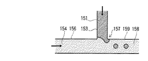
これらの図において、150は第1のダブルエマルション・マイクロカプセル生成チップ、151は第1分散相、152はその第1分散相の供給口、153は第1分散相151を供給する第1のマイクロチャネル、154は第1連続相、155はその第1連続相154の供給口、156はその第1連続相154が供給される第2のマイクロチャネル、157は第1と第2のマイクロチャネル153と156とが交差する第1の交差部(T型交差部)、158は第2分散相、159はその第2分散相158が供給される第3のマイクロチャネル、160はその第2分散相の排出口、161は接続流路、170は第2のダブルエマルション・マイクロカプセル生成チップ、171は第2分散相の排出口160に接続流路161を介して接続される第2分散相の供給口、172は第2分散相158が供給される第4のマイクロチャネル、173は第2連続相、174は第2連続相の供給口、175は第2連続相173が供給される第5のマイクロチャネル、176は第4と第5のマイクロチャネル172と175が交差する第2の交差部(T型交差部)、177はダブルエマルション・マイクロカプセル、178はそのダブルエマルション・マイクロカプセル177の搬送マイクロチャネル、179はダブルエマルション・マイクロカプセル177の排出口である。
【0030】
この実施例では、第1の交差部(T型交差部)157を有する第1のダブルエマルション・マイクロカプセル生成チップ150と第2の交差部(T型交差部)176を有する第2のダブルエマルション・マイクロカプセル生成チップ170とを接続流路161で接続して、2つのT型マイクロチャネル157,176を組み合わせることにより、2段のT型マイクロチャネルを有するマイクロチャネルを容易に構築することができる。
【0031】
図7は本発明の第2実施例を示すダブルエマルション・マイクロカプセル生成装置の全体模式図、図8は図7のE部(第1の交差部)拡大図、図9は図7のF部(第2の交差部)拡大図である。
【0032】
これらの図において、ダブルエマルション・マイクロカプセル生成装置は、ダブルエマルション・マイクロカプセル生成チップ200、第1連続相201の供給口202、その供給口202から分流される、第1連続相201が供給される第1のマイクロチャネル203及び第2のマイクロチャネル204、第1分散相205の供給口206、その供給口206から第1分散相205が供給される第3のマイクロチャネル207、第1、第2のマイクロチャネル203,204と第3のマイクロチャネル207が交差する第1の交差部(十字型交差部)208、第2分散相209が供給される第4のマイクロチャネル210、第2連続相211の供給口212、その第2連続相211が供給される第5のマイクロチャネル213、第4と第5のマイクロチャネル210と213が交差する第2の交差部(T型交差部)214、ダブルエマルション・マイクロカプセル215が搬送されるマイクロチャネル216、ダブルエマルション・マイクロカプセル215の排出口217からなる。
【0033】
このように、この実施例では、十字型マイクロチャネル208とT字型マイクロチャネル214を組み合わせることによりダブルエマルション・マイクロカプセルを生成することができる。
【0034】
また、この実施例では、第1の交差部(十字型交差部)208と第2の交差部(T型交差部)214の型を入れ換え、第1の交差部にT型マイクロチャネル、第2の交差部に十字型マイクロチャネルを用いることも可能である。
【0035】
図10は本発明の第2実施例の変形例を示すダブルエマルション・マイクロカプセル生成装置の全体模式図、図11は図10のG部(第1の交差部)拡大図、図12は図10のH部(第2の交差部)拡大図である。
【0036】
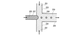
これらの図において、250は第1のダブルエマルション・マイクロカプセル生成チップ、251は第1連続相、252はその第1連続相251の供給口、253は供給口252から分流する第1連続相251が供給される第1のマイクロチャネル、254は供給口252から分流する第1連続相251が供給される第2のマイクロチャネル、255は第1分散相、256は第1分散相の供給口、257はその第1分散相が供給される第3のマイクロチャネル、258は第1、第2のマイクロチャネル253,254と、第3のマイクロチャネル257とが交差する第1の交差部(十字型交差部)、259は第2分散相、260はその第2分散相259が供給される第4のマイクロチャネル、261は第2分散相259の排出口、262は接続流路、270は第2のダブルエマルション・マイクロカプセル生成チップ、271は第2分散相259の排出口261に接続流路262を介して接続される第2分散相の供給口、272はその第2分散相259の供給口271に接続され、第2分散相259が供給される第5のマイクロチャネル、274は第2連続相273の供給口、275は第2連続相273が供給される第6のマイクロチャネル、276は第5と第6のマイクロチャネル272と275が交差する第2の交差部(T型交差部)、277はダブルエマルション・マイクロカプセル、278はそのダブルエマルション・マイクロカプセル277の搬送マイクロチャネル、279はダブルエマルション・マイクロカプセル277の排出口である。
【0037】
この実施例では、第1の交差部(十字型交差部)258を有する第1のダブルエマルション・マイクロカプセル生成チップ250と第2の交差部(T型交差部)276を有する第2のダブルエマルション・マイクロカプセル生成チップ270とを接続流路262で接続することにより、異なった態様の十字型マイクロチャネルとT型マイクロチャネルとを組み合わせたマイクロチャネルを容易に構築することができる。
【0038】
上記した図4と図10によれば、異なる材質のマイクロチャネルを用いても、接続流路161,262で接続することによって、ダブルエマルション・マイクロカプセルを生成することができる。
【0039】
例えば、第1のダブルエマルション・マイクロカプセル生成チップ150,250をアクリル製、第2のダブルエマルション・マイクロカプセル生成チップ170,270をガラス製にすることにより、W/O/W型エマルション・マイクロカプセルが生成できる。
【0040】
図13は本発明の第2実施例の更なる変形例を示すダブルエマルション・マイクロカプセル生成装置の全体構成図であり、図13(a)はその上面図、図13(b)は図13(a)のA−A線断面図である。
【0041】
これらの図において、280は第1のダブルエマルション・マイクロカプセル生成チップ、281は第1連続相、282はその第1連続相281の供給口、283は供給口282から分流する第1連続相281が供給される第1のマイクロチャネル、284は供給口282から分流する第1連続相281が供給される第2のマイクロチャネル、285は第1分散相、286は第1分散相285の供給口、287はその第1分散相285が供給される第3のマイクロチャネル、288は第1、第2、第3のマイクロチャネル283,284,287とが交差する第1の交差部(十字型交差部)、289は第2分散相、290はその第2分散相289が供給される第4のマイクロチャネル、291は第2分散相の排出口、292は接続流路、293は第1のダブルエマルション・マイクロカプセル生成チップ280の下部に配置される第2のダブルエマルション・マイクロカプセル生成チップ、294は接続流路292に接続され、第2分散相289が供給される第5のマイクロチャネル、295は第2連続相、296は第2連続相295の供給口、297は第2連続相295が供給される第6のマイクロチャネル、298は第5、第6のマイクロチャネル294,297とが交差する第2の交差部(T型交差部)、299Aはダブルエマルション・マイクロカプセルの搬送マイクロチャネル、299Bはダブルエマルション・マイクロカプセルの排出口である。
【0042】
この実施例の場合は、上記したように、第1のダブルエマルション・マイクロカプセル生成チップ280と第2のダブルエマルション・マイクロカプセル生成チップ293とを上下に重ねるようにしている。
【0043】
また、図4と図10の場合は流路で横方向に接続した場合であるが、この図13の場合は上下に重ねた場合であり、図4と図10と同様に異なる材質のマイクロチャネルを用いてもよい。
【0044】
図14は本発明の第3実施例を示すダブルエマルション・マイクロカプセル生成装置の全体模式図である。
【0045】
この図において、300はダブルエマルション・マイクロカプセル生成チップ、301は第1連続相、302はその第1連続相301の供給口、303はその第1連続相301が供給される第1のマイクロチャネル、304は第1分散相(1)、305はその第1分散相(1)304の供給口、306はその第1分散相(1)304が供給される第2のマイクロチャネル、307は第1、第2のマイクロチャネル303と306とが交差する交差部(T型交差部)、308は交差部(T型交差部)307より下流の第2分散相(1)、309はその第2分散相(1)308が供給される第3のマイクロチャネル、310は第1分散相(2)、311は第1分散相(2)310の供給口、312はその第1分散相(2)310が供給される第4のマイクロチャネル、313は第3、第4のマイクロチャネル309と312とが交差する交差部(T型交差部)、314は交差部(T型交差部)313より下流の第2分散相(2)、315はその第2分散相(2)314が供給される第5のマイクロチャネル、316は第2連続相、317はその第2連続相316の供給口、318は第2連続相316が供給される第6のマイクロチャネル、319は第5、第6のマイクロチャネル315と318とが交差する交差部(T型交差部)、320は生成されるダブルエマルション・マイクロカプセル、321はダブルエマルション・マイクロカプセル320の搬送マイクロチャネル、322はそのダブルエマルション・マイクロカプセル320の排出口である。
【0046】
この実施例では、分散相の供給口を増やすようにしている。つまり、第1分散相の流量を増加させることにより、ダブルエマルション・マイクロカプセル内に含まれる液滴量を増やすようにしている。
【0047】
図15は本発明の第4実施例を示すダブルエマルション・マイクロカプセル生成装置の全体模式図である。
【0048】
この図において、400はダブルエマルション・マイクロカプセル生成チップ、401は第1連続相、402はその第1連続相401の供給口、403はその第1連続相401が供給される第1のマイクロチャネル、404は第1分散相、405はその第1分散相404の供給口、406はその第1分散相404が供給される第2のマイクロチャネル、407は第1、第2のマイクロチャネル403と406との交差部(第1T型交差部)、408は交差部(T型交差部)407より下流の第2分散相(1)、409はその第2分散相(1)408が供給される第3のマイクロチャネル、410はその第2分散相(1)408が供給される第3のマイクロチャネル409と第3のマイクロチャネル409の交差部(第2のT型交差部)、408Aは排出されない残りの第2分散相(2)、411は交差部410から排出される一部の第1連続相、412はその第1連続相411の排出用マイクロチャネル、413は第1連続相411の排出口、414は排出されない残りの第2分散相(1)408が供給される第4のマイクロチャネル、415は第2連続相、416はその第2連続相415の供給口、417は第2連続相415が供給される第5のマイクロチャネル、418は第4、第5のマイクロチャネル414と417とが交差する交差部(T型交差部)、419は生成したダブルエマルション・マイクロカプセル、420は生成したダブルエマルション・マイクロカプセル419の搬送マイクロチャネル、421は生成したダブルエマルション・マイクロカプセル419の排出口である。
【0049】
この実施例でも、第3実施例と同様に、第1連続相の流量の比率を分散相に対して減少させることにより、ダブルエマルション・マイクロカプセル内に含まれる液滴量を増やすようにしている。
【0050】
図16は本発明の第5実施例を示すダブルエマルション・マイクロカプセル生成装置の全体模式図である。
【0051】
この図において、500はダブルエマルション・マイクロカプセル生成チップ、501は第1連続相、502はその第1連続相501の供給口、503はその供給口502から分流される第1連続相501が供給される第1のマイクロチャネル、504は供給口502から分流される第1連続相501が供給される第2のマイクロチャネル、505は第1分散相、506は第1分散相505の供給口、507はその第1分散相505が供給される第3のマイクロチャネル、508は第1、第2、第3のマイクロチャネル503,504,507とが交差する第1の交差部(十字型交差部)、509は第2分散相(1)、510はその第2分散相(1)509が供給される第4のマイクロチャネル、511は第2の交差部(十字型交差部)、512は第2分散相(1)509中の第1連続相501の一部が排出される第1の排出用マイクロチャネル、513は第1連続相501の第1の排出口、514は第1連続相501の一部が排出される第2の排出用マイクロチャネル、515は第1連続相501の排出口、516は第2の交差部511に接続される排出されない残りの第2分散相(1)509が供給される第5のマイクロチャネル、517は第1の第2連続相、518は第1の第2連続相517の供給口、519は第1の第2連続相517が供給される第6のマイクロチャネル、520は第2の第2連続相、521は第2の第2連続相520の供給口、522は第2の第2連続相520が供給される第7のマイクロチャネル、523は第3の交差部(十字型交差部)、524は生成したダブルエマルション・マイクロカプセル、525は生成したダブルエマルション・マイクロカプセル524の搬送マイクロチャネル、526は生成したダブルエマルション・マイクロカプセル524の排出口である。
【0052】
図17は本発明の第6実施例を示すダブルエマルション・マイクロカプセル生成装置の全体模式図である。
【0053】
この図において、600はダブルエマルション・マイクロカプセル生成チップ、601は第1連続相、602はその第1連続相601の供給口、603は供給口602から分流される第1連続相601が供給される第1のマイクロチャネル、604は供給口602から分流される第1連続相601が供給される第2のマイクロチャネル、605は第1分散相、606は第1分散相605の供給口、607はその第1分散相605が供給される第3のマイクロチャネル、608は第1、第2、第3のマイクロチャネル603,604,607とが交差する第1の交差部(十字型交差部)、609は第2分散相、610はその第2分散相609が供給される第4のマイクロチャネル、611は第2の交差部(十字型交差部)、612は第2分散相609の一部が排出される第1の排出用マイクロチャネル、613は第2分散相609の第1の排出口、614は第2分散相609の一部が排出される第2の排出用マイクロチャネル、615は第2分散相609の第2の排出口、616は第2の交差部611に接続される排出されない残りの第2分散相609が供給される第5のマイクロチャネル、617は第2連続相、618は第2連続相617の供給口、619は第2連続相617が分流され供給される第6のマイクロチャネル、620は第2連続相617が分流され、供給される第7のマイクロチャネル、621は第3の交差部(十字型交差部)、622は生成したダブルエマルション・マイクロカプセル、623は生成したダブルエマルション・マイクロカプセル622の搬送マイクロチャネル、624は生成したダブルエマルション・マイクロカプセル622の排出口である。
【0054】
図18は本発明の実施例を示す生成されたW/O/W型ダブルエマルションを示す図であり、アクリル製十字型マイクロチャネル(分散相側40μm×40μm、連続相側100μm×100μm)とガラス製T型マイクロチャネル(分散相側40μm×40μm、連続相側100μm×100μm)によって生成されたダブルエマルション・マイクロカプセルの例である。流量は、第1分散相0.01ml/h、第1連続相0.5ml/h、第2連続相25ml/hである。
【0055】
図19は本発明の第1のダブルエマルション・マイクロカプセルの液滴径および内部に含まれる液滴数を制御するための装置の模式図である。
【0056】
この図において、ダブルエマルション・マイクロカプセル生成装置は、ダブルエマルション・マイクロカプセル生成チップ700、第1連続相701の供給口702、その供給口702から第1連続相701が供給される第1のマイクロチャネル703、第1分散相704の供給口705、その供給口705から第1分散相704が供給される第2のマイクロチャネル706、その第1、第2のマイクロチャネル703と706が交差する第1の交差部(第1のT型マイクロチャネ707、第2分散相708が供給される第3のマイクロチャネル709、第2連続相710の供給口711、第2連続相710が供給される第4のマイクロチャネル712、その第3、第4のマイクロチャネル712と709が交差する第2の交差部(第2のT型マイクロチャネル)713、ダブルエマルション・マイクロカプセル714が供給される搬送マイクロチャネル715、ダブルエマルション・マイクロカプセル714の排出口716からなる。
【0057】
また、第1連続相701の供給口702の経路には第1の流量可変ポンプ723が、第1分散相704の供給口705の経路には第2の流量可変ポンプ724が、第2連続相710の供給口711の経路には第3の流量可変ポンプ725がそれぞれ接続されている。
【0058】
さらに、粒子径・生成数の測定装置726では、第1の交差部(第1のT型マイクロチャネル)707での粒子径・生成数の測定を、粒子径・生成数の測定装置727では、第2の交差部(第1のT型マイクロチャネル)713での粒子径・生成数の測定をそれぞれ行うようにしている。それらの粒子径・生成数の測定装置726,727からの情報はコントローラ722に取り込まれ、コンピュータ(PC)721によって予め設定された所定の粒子径・生成数になるように、第1の流量可変ポンプ723、第2の流量可変ポンプ724及び第3の流量可変ポンプ725が制御される。
【0059】
このように、図19は、ダブルエマルション・マイクロカプセル内部に含まれる液滴径および液滴数をカメラ、静電容量等で計測し、第1の流量可変ポンプ723、第2の流量可変ポンプ724を制御する。さらに、第2の交差部713においても液滴径および液滴数を計数して、第3の流量可変ポンプ725を制御する。
【0060】
図20は本発明の第2のダブルエマルション・マイクロカプセルの液滴径および内部に含まれる液滴数を制御するための装置の模式図である。
【0061】
この図において、800はダブルエマルション・マイクロカプセル生成チップ、801は第1連続相、802はその第1連続相801の供給口、803はその第1連続相801が供給される第1のマイクロチャネル、804は第1分散相、805はその第1分散相804の供給口、806はその第1分散相801が供給される第3のマイクロチャネル、807は第1、第2のマイクロチャネル803と806との第1の交差部(T型交差部)、808は第1の交差部807に接続される第1連続相801が供給される第3のマイクロチャネル、809は第2の交差部(T型交差部)、810はその第3のマイクロチャネル808から分岐して第1連続相801の一部が排出されるマイクロチャネル、811は第1連続相801の排出口、812は第2連続相、813は第2連続相812の供給口、814はその第2分散相812が供給される第5のマイクロチャネル、815は第3、第5のマイクロチャネル808と814との第3の交差部(T型交差部)、816は第3の交差部815より生成されるダブルエマルション・マイクロカプセル、817はそのダブルエマルション816の生成マイクロチャネル、818はそのダブルエマルション・マイクロカプセル816の排出口である。
【0062】
また、第1連続相801の供給口802の経路には第1の流量可変ポンプ823が、第1分散相804の供給口805の経路には第2の流量可変ポンプ824が、第2連続相812の供給口813の経路には第3の流量可変ポンプ825が、第1連続相の排出口811の経路には流量可変バルブ828がそれぞれ接続されている。
【0063】
さらに、粒子径・生成数の測定装置826では、第1の交差部(T型交差部)807での粒子径・生成数の測定を、粒子径・生成数の測定装置827では、第3の交差部(T型交差部)815での粒子径・生成数の測定をそれぞれ行うようにしている。それらの粒子径・生成数の測定装置826,827からの情報はコントローラ822に取り込まれ、コンピュータ(PC)821によって予め設定された所定の粒子径・生成数になるように、第1の流量可変ポンプ823、第2の流量可変ポンプ824及び第3の流量可変ポンプ825、流量可変バルブ828が制御される。
【0064】
上述した図20は、ダブルエマルション・マイクロカプセル内部に含まれる液滴数をさらに精密に制御する場合である。液滴数の制御は、第1連続相を流量可変バルブ828を通じて排出することにより、さらに、精密な制御を行う。第3の交差部815において液滴径及び液滴数を計数して、第3の流量可変ポンプ825を制御するが、場合によっては第1及び第2流量可変ポンプ823,824も制御する。
【0065】
上記した各実施例においては、ダブルエマルション・マイクロカプセルが排出されるマイクロチャネルは1つであった。したがって、量産化のためには、個別のマイクロチャネル装置を複数個設ける必要がある。
【0066】
これを回避して、量産化を図るために、以下のように構成する。
【0067】
図21は本発明の第1の量産型のダブルエマルション・マイクロカプセルの生成装置(デバイス)の模式図である。
【0068】
この図において、900はダブルエマルション・マイクロカプセルの生成装置、901,902は第1連続相の供給口、903は分散相の供給口、904,905は第1の交差部、906,907は第2連続相の供給口、908,909は第2の交差部、910はダブルエマルション・マイクロカプセル回収口である。
【0069】
図22は本発明の第2の量産型のダブルエマルション・マイクロカプセルの生成装置(デバイス)の模式図である。
【0070】
この図において、950はダブルエマルション・マイクロカプセルの生成装置、951は第1連続相の供給口、952は分散相の供給口、953,954は第1の交差部、955,956は第2連続相の供給口、957,958は第2の交差部、959はダブルエマルエマルション・マイクロカプセル回収口である。
【0071】
なお、上記実施例において、T型交差部は三路交差部、十字型交差部は四路交差部の一例として示したに過ぎないものである。
【0072】
本発明は、交差するマイクロチャネルを組み合わせることにより、種々の態様のダブルエマルション・マイクロカプセルを簡便にしかも容易に作製することができる。例えば、水溶液、油など親和性の低い複数の液体を用いて微小なマイクロスフェア、エマルション・マイクロカプセルを作製することができる。
【0073】
なお、本発明は上記実施例に限定されるものではなく、本発明の趣旨に基づいて種々の変形が可能であり、これらを本発明の範囲から排除するものではない。
【0074】
【発明の効果】
以上、詳細に説明したように、本発明によれば、交差するマイクロチャネルを組み合わせることにより、種々の態様のダブルエマルション・マイクロカプセルを簡便にしかも容易に作製することができる。
【図面の簡単な説明】
【図1】本発明の第1実施例を示すダブルエマルション・マイクロカプセル生成装置の全体模式図である。
【図2】図1のA部(第1の交差部)拡大図である。
【図3】図1のB部(第2の交差部)拡大図である。
【図4】本発明の第1実施例の変形例を示すダブルエマルション・マイクロカプセル生成装置の全体模式図である。
【図5】図4のC部(第1の交差部)拡大図である。
【図6】図4のD部(第2の交差部)拡大図である。
【図7】本発明の第2実施例を示すダブルエマルション・マイクロカプセル生成装置の全体模式図である。
【図8】図7のE部(第1の交差部)拡大図である。
【図9】図7のF部(第2の交差部)拡大図である。
【図10】本発明の第2実施例の変形例を示すダブルエマルション・マイクロカプセル生成装置の全体模式図である。
【図11】図10のG部(第1の交差部)拡大図である。
【図12】図10のH部(第2の交差部)拡大図である。
【図13】本発明の第2実施例の更なる変形例を示すダブルエマルション・マイクロカプセル生成装置の全体構成図である。
【図14】本発明の第3実施例を示すダブルエマルション・マイクロカプセル生成装置の全体模式図である。
【図15】本発明の第4実施例を示すダブルエマルション・マイクロカプセル生成装置の全体模式図である。
【図16】本発明の第5実施例を示すダブルエマルション・マイクロカプセル生成装置の全体模式図である。
【図17】本発明の第6実施例を示すダブルエマルション・マイクロカプセル生成装置の全体模式図である。
【図18】本発明の実施例を示す生成されたW/O/W型ダブルエマルション・マイクロカプセルを示す図である。
【図19】本発明の第1のダブルエマルション・マイクロカプセルの液滴径および内部に含まれる液滴数を制御するための装置の模式図である。
【図20】本発明の第2のダブルエマルション・マイクロカプセルの液滴径および内部に含まれる液滴数をさらに精密に制御するための装置の模式図である。
【図21】本発明の第1の量産型のダブルエマルション・マイクロカプセルの生成装置(デバイス)の模式図である。
【図22】本発明の第2の量産型のダブルエマルション・マイクロカプセルの生成装置(デバイス)の模式図である。
【符号の説明】
100,200,300,400,500,600,700,800 ダブルエマルション・マイクロカプセル生成チップ
101,154,201,251,281,301,308,401,408,411,501,601,701,801 第1連続相
102,155,202,252,282,302,402,502,602,702,802,901,902,951 第1連続相の供給口
103,106,109,112,115,153,156,158,172,175,178,203,204,207,210,213,216,253,254,257,260,272,275,278,283,284,287,290,294,297,299A,303,306,309,312,315,318,321,403,406,409,412,414,417,420,503,504,507,510,512,514,516,519,522,525,603,604,607,610,612,614,616,619,620,623,703,706,709,712,715,803,806,808,810,814,817 マイクロチャネル
104,151,205,255,285,304,404,505,605,704,804 第1分散相
105,152,206,256,286,305,405,506,606,705,805 第1分散相の供給口
107,157,208,258,288,508,608,707,807,904,905,953,954 第1の交差部
108,159,209,259,289,310,408A,509,609,708 第2分散相
110,173,211,273,295,316,415,517,520,617,710,812 第2連続相
111,174,212,274,296,317,416,518,521,618,711,813,906,907,955,956 第2連続相の供給口
113,176,214,276,298,511,611,713,809,908,909,957,958 第2の交差部
114,177,215,277,320,419,524,622,714ダブルエマルション・マイクロカプセル
116,179,217,279,299B,322,421,526,624,716 ダブルエマルション・マイクロカプセルの排出口
150,250,280 第1のダブルエマルション・マイクロカプセル生成チップ
160,261,291 第2分散相の排出口
161,262,292 接続流路
170,270,293 第2のダブルエマルション・マイクロカプセル生成チップ
171,271,311 第2分散相の供給口
307,313,319,407,408,410,418 交差部
413,811 第1連続相の排出口
513 第1連続相の第1の排出口
515 第1連続相の第2の排出口
523,621,815 第3の交差部
613 第1連続相の第1の排出口
615 第1連続相の第2の排出口
721,821 コンピュータ
722,822 コントローラ
723,823 第1の流量可変ポンプ
724,824 第2の流量可変ポンプ
725,825 第3の流量可変ポンプ
726,727,826,827 粒子径・生成数の測定装置
816 ダブルエマルション・マイクロカプセル
818 ダブルエマルション・マイクロカプセルの排出口
828 流量可変バルブ
900,950 ダブルエマルション・マイクロカプセルの生成装置
903,952 第1分散相の供給口
910,959 ダブルエマルション・マイクロカプセル回収口[0001]
TECHNICAL FIELD OF THE INVENTION
The present invention relates to a method for producing double emulsion microcapsules, and relates to a technique for producing microspheres and emulsion microcapsules using a plurality of liquids having low affinity such as aqueous solutions and oils.
[0002]
[Prior art]
The inventors of the present application have already filed a patent application for the method and apparatus for producing emulsion microcapsules as
[0003]
[Patent Document 1]
WO02 / 068104A1 page 6-7 FIG.
[0004]
[Problems to be solved by the invention]
The present invention further develops the above-mentioned prior art, and relates to the double emulsion microcapsule generation apparatus, by easily and easily producing double emulsion microcapsules of various embodiments by combining crossing microchannels. It is an object of the present invention to provide a double emulsion / microcapsule generation device capable of performing the above-mentioned operations.
[0005]
[Means for Solving the Problems]
The present invention, in order to achieve the above object,
[1] In the double emulsion / microcapsule generator, a first intersection where the first continuous phase intersects with the first dispersed phase, and a second dispersed phase downstream of the first intersection with the second continuous phase. A double emulsion microcapsule generation chip comprising a microchannel formed with a second intersection where the phase intersects is provided.
[0006]
[2] In the double emulsion / microcapsule generator according to the above [1], W / O / W / O / H is produced by a hydrophobizing treatment near the first intersection and / or a hydrophilization treatment near the second intersection. A W-type double emulsion is generated, and conversely, an O / W / O-type double emulsion is generated by a hydrophilizing treatment near the first intersection and / or a hydrophobic treatment near the second intersection. Become.
The vicinity of the second intersection is hydrophilized to generate a W / O / W double emulsion, and the vicinity of the first intersection is hydrophilized to generate an O / W / O double emulsion. Let me do it.
[0007]
[3] In the double emulsion microcapsule generation device, a first double emulsion microcapsule generation chip having a first intersection where a first continuous phase and a first dispersed phase intersect, a second continuous phase and a second A second double-emulsion microcapsule generation chip having a second intersection where two disperse phases intersect, a first double-emulsion microcapsule generation chip and a second double-emulsion microcapsule generation chip And a connection flow path for connection.
[0008]
[4] In the double emulsion / microcapsule generator, a four-way intersection where the first dispersed phase intersects with the first continuous phase supplied from the divided two sides, and a second part which is downstream of the four-way intersection. It is characterized by comprising a double emulsion microcapsule generating chip comprising a microchannel in which a three-way intersection where the dispersed phase and the second continuous phase intersect is formed.
[0009]
[5] In the double emulsion / microcapsule generation device, a first double emulsion / microcapsule generation chip having a four-way intersection where the first dispersed phase and the first continuous phase supplied from the two divided sides intersect; A second double emulsion microcapsule generation chip having a three-way intersection where a second dispersed phase and a second continuous phase intersect, and the first double emulsion microcapsule generation chip and the second double emulsion microcapsule. And a connection flow path for connecting the microcapsule generation chip.
[0010]
[6] In the double emulsion / microcapsule generation device according to the above [3] or [5], the connection flow path is arranged in a horizontal direction, and the first double emulsion / microcapsule generation chip and the second double emulsion are provided. -It is characterized in that a microcapsule generation chip is juxtaposed.
[0011]
[7] In the double emulsion / microcapsule generation device according to the above [3] or [6], the connection flow path is arranged vertically, and the first double emulsion / microcapsule generation chip and the second double emulsion are provided. -It is characterized by laminating a microcapsule generation chip.
[0012]
[8] In the double emulsion / microcapsule generator, an intersection where the first continuous phase intersects with a plurality of dispersed phases, and a further intersection where a further dispersed phase intersects with the second continuous phase downstream of the first continuous phase. And a double emulsion microcapsule generation chip comprising a microchannel having the following.
[0013]
[9] The double emulsion microcapsule generator according to the above [8], wherein the plurality of dispersed phases are a first dispersed phase and a second dispersed phase.
[0014]
[10] In the double emulsion / microcapsule generation device, a first intersection where the first continuous phase intersects with the first dispersed phase, and a second continuous phase downstream of the first intersection with the second continuous phase. A double-emulsion microcapsule generating chip comprising a microchannel formed with a second intersection where the phase intersects, and a first variable flow rate pump connected to the path of the first continuous phase; A second variable flow pump is connected to the path of the first dispersed phase, a third variable flow pump is connected to the path of the second continuous phase, and particles are connected to the first and second intersections. A first flow variable pump, a second variable flow pump, and a diameter / generation number measuring device, so that a predetermined particle diameter / generation number is set in advance based on information from the measuring device. Control with the third variable flow pump And wherein the Rukoto.
[0015]
[11] In the double emulsion / microcapsule generator, a first intersection where the first continuous phase intersects the first dispersed phase, and a part of the first continuous phase downstream of the first intersection. And a third intersection where a second continuous phase intersects with a first intersection at which a path for discharging the micro-capsules is formed. At the same time, a first variable flow rate pump is connected to the path of the first continuous phase, a second variable flow rate pump is connected to the path of the first dispersed phase, and a part of the first continuous phase is discharged. A variable flow rate valve is connected to the path to be connected, a third variable flow rate pump is connected to the path of the second continuous phase, and a measuring device for measuring the particle diameter and the number of particles generated is provided at the first and third intersections. Preset based on information from the measuring device. Controlling the first variable flow rate pump, the second variable flow rate pump, the variable flow rate valve, and the third variable flow rate pump so that the predetermined particle diameter and the generated number are obtained. .
[0016]
[12] In the double emulsion / microcapsule generation device, a first four-way intersection where the first dispersed phase intersects the diverted first continuous phase, and two directions downstream of the first four-way intersection. A four-way intersection having a path for discharging the first continuous phase, and a third four-way intersection where the second continuous phase intersects from two directions downstream of the second four-way intersection. A double-emulsion microcapsule generation chip comprising microchannels.
[0017]
[13] In the double emulsion / microcapsule generation device, a first four-way intersection where the first dispersed phase intersects the diverted first continuous phase, and two directions downstream of the first four-way intersection. A second four-way intersection having a path for discharging the second continuous phase, and a third four-way intersection where the second continuous phase diverted downstream of the second four-way intersection intersects It is characterized by comprising a double emulsion / microcapsule generation chip comprising a microchannel.
[0018]
[14] In the double emulsion / microcapsule generator, a first intersection where the dispersed phase intersects the first continuous phase and a second intersection where the second continuous phase intersects downstream of the first intersection. Are arranged in parallel in a network, and the junction downstream of the second intersection is used as a recovery port for double emulsion microcapsules.
[0019]
[15] The double-emulsion microcapsule generator according to the above [14], characterized in that the supply ports of the first continuous phase adjacent in parallel are shared.
[0020]
BEST MODE FOR CARRYING OUT THE INVENTION
Hereinafter, embodiments of the present invention will be described in detail.
[0021]
FIG. 1 is an overall schematic view of a double emulsion / microcapsule generation device showing a first embodiment of the present invention, FIG. 2 is an enlarged view of a portion A (first intersection) of FIG. 1, and FIG. 3 is a portion B of FIG. (2nd intersection part) It is an enlarged view.
[0022]
In these figures, the double emulsion / microcapsule generation device includes a double emulsion /
[0023]
Thus, in this embodiment, the
[0024]
For example, when using the
[0025]
Further, by adding a hydrophilic surfactant (for example, sodium dodecyl sulfate; SDS) to the second
[0026]
Further, since liquids having different wettabilities are formed as liquid droplets at the
[0027]
Alternatively, a plurality of microchannels (106) or the like arranged in the horizontal direction may be arranged, and a plurality of intersections may be arranged.
[0028]
FIG. 4 is an overall schematic view of a double emulsion microcapsule generation apparatus showing a modification of the first embodiment of the present invention, FIG. 5 is an enlarged view of a portion C (first intersection) of FIG. 4, and FIG. It is the D section (2nd intersection part) enlarged view of (a).
[0029]
In these figures, 150 is a first double emulsion / microcapsule generation chip, 151 is a first dispersed phase, 152 is a supply port for the first dispersed phase, and 153 is a first microparticle supplying the first dispersed
[0030]
In this embodiment, a first double emulsion
[0031]
7 is an overall schematic diagram of a double emulsion / microcapsule generation device showing a second embodiment of the present invention, FIG. 8 is an enlarged view of a portion E (first intersection) of FIG. 7, and FIG. 9 is a portion F of FIG. (2nd intersection part) It is an enlarged view.
[0032]
In these figures, the double emulsion microcapsule generation device is supplied with a double emulsion
[0033]
Thus, in this embodiment, a double emulsion microcapsule can be generated by combining the
[0034]
In this embodiment, the first intersection (cross-shaped intersection) 208 and the second intersection (T-shaped intersection) 214 are interchanged so that the first intersection has a T-type microchannel and the second intersection has a second shape. It is also possible to use a cross-shaped microchannel at the intersection of.
[0035]
FIG. 10 is an overall schematic diagram of a double emulsion / microcapsule generation apparatus showing a modification of the second embodiment of the present invention, FIG. 11 is an enlarged view of a portion G (first intersection) in FIG. 10, and FIG. It is the H section (2nd intersection part) enlarged view of (a).
[0036]
In these figures, 250 is a first double emulsion microcapsule generation chip, 251 is a first continuous phase, 252 is a supply port of the first
[0037]
In this embodiment, a first double emulsion
[0038]
According to FIGS. 4 and 10 described above, even if microchannels of different materials are used, a double emulsion microcapsule can be generated by connecting the microchannels with the
[0039]
For example, the first double emulsion
[0040]
FIG. 13 is an overall configuration diagram of a double emulsion / microcapsule generation device showing a further modification of the second embodiment of the present invention. FIG. 13 (a) is a top view thereof, and FIG. It is AA line sectional drawing of a).
[0041]
In these figures,
[0042]
In the case of this embodiment, as described above, the first double emulsion /
[0043]
4 and FIG. 10 show the case where they are connected in the horizontal direction by the flow path, while FIG. 13 shows the case where they are vertically stacked, and the microchannels made of different materials as in FIG. 4 and FIG. May be used.
[0044]
FIG. 14 is an overall schematic diagram of a double emulsion / microcapsule generation device showing a third embodiment of the present invention.
[0045]
In this figure, 300 is a double emulsion microcapsule generation chip, 301 is a first continuous phase, 302 is a supply port for the first
[0046]
In this embodiment, the number of supply ports for the dispersed phase is increased. That is, by increasing the flow rate of the first dispersed phase, the amount of droplets contained in the double emulsion microcapsules is increased.
[0047]
FIG. 15 is an overall schematic diagram of a double emulsion / microcapsule generation device showing a fourth embodiment of the present invention.
[0048]
In this figure, 400 is a double emulsion microcapsule generation chip, 401 is a first continuous phase, 402 is a supply port for the first
[0049]
In this embodiment, as in the third embodiment, the amount of liquid droplets contained in the double emulsion microcapsules is increased by reducing the ratio of the flow rate of the first continuous phase to that of the dispersed phase. .
[0050]
FIG. 16 is an overall schematic diagram of a double emulsion / microcapsule generation device showing a fifth embodiment of the present invention.
[0051]
In this figure, 500 is a double emulsion microcapsule generation chip, 501 is a first continuous phase, 502 is a supply port of the first
[0052]
FIG. 17 is an overall schematic diagram of a double emulsion / microcapsule generation device showing a sixth embodiment of the present invention.
[0053]
In this figure, 600 is a double emulsion microcapsule generation chip, 601 is a first continuous phase, 602 is a supply port of the first
[0054]
FIG. 18 is a view showing a generated W / O / W type double emulsion showing an example of the present invention, in which acrylic cross microchannels (dispersed phase side 40 μm × 40 μm,
[0055]
FIG. 19 is a schematic diagram of an apparatus for controlling the droplet diameter and the number of droplets contained in the first double emulsion microcapsule of the present invention.
[0056]
In this figure, a double emulsion / microcapsule generation device includes a double emulsion /
[0057]
Further, a first
[0058]
Further, the particle diameter / generation
[0059]
19, the diameter and the number of droplets contained in the double emulsion microcapsule are measured with a camera, capacitance, and the like, and the first
[0060]
FIG. 20 is a schematic diagram of an apparatus for controlling the droplet diameter and the number of droplets contained in the second double emulsion microcapsule of the present invention.
[0061]
In this figure, 800 is a chip for generating double emulsion microcapsules, 801 is a first continuous phase, 802 is a supply port for the first
[0062]
Also, a first
[0063]
Further, the particle diameter / generation
[0064]
FIG. 20 described above shows a case where the number of droplets contained in the double emulsion microcapsules is controlled more precisely. The number of droplets is controlled more precisely by discharging the first continuous phase through the variable
[0065]
In each of the embodiments described above, there was one microchannel from which the double emulsion microcapsules were discharged. Therefore, for mass production, it is necessary to provide a plurality of individual microchannel devices.
[0066]
To avoid this and achieve mass production, the following configuration is adopted.
[0067]
FIG. 21 is a schematic view of a first mass-production type double emulsion microcapsule generation device (device) of the present invention.
[0068]
In this figure, 900 is an apparatus for producing double emulsion microcapsules, 901 and 902 are supply ports for the first continuous phase, 903 is a supply port for the dispersed phase, 904 and 905 are the first intersections, and 906 and 907 are the first intersections. The two continuous phase supply ports, 908 and 909 are second intersections, and 910 is a double emulsion / microcapsule recovery port.
[0069]
FIG. 22 is a schematic view of a second mass-production type double emulsion microcapsule generation device (device) of the present invention.
[0070]
In this figure, 950 is a double emulsion microcapsule generator, 951 is a supply port of the first continuous phase, 952 is a supply port of the dispersed phase, 953 and 954 are the first intersections, and 955 and 956 are the second continuous sections. A phase supply port, 957 and 958 are second intersections, and 959 is a double emulsion / microcapsule recovery port.
[0071]
In the above embodiment, the T-shaped intersection is merely an example of a three-way intersection, and the cross-shaped intersection is merely an example of a four-way intersection.
[0072]
According to the present invention, various types of double emulsion microcapsules can be easily and easily prepared by combining the crossing microchannels. For example, minute microspheres and emulsion microcapsules can be manufactured using a plurality of liquids having low affinity such as an aqueous solution and oil.
[0073]
It should be noted that the present invention is not limited to the above embodiment, and various modifications are possible based on the spirit of the present invention, and these are not excluded from the scope of the present invention.
[0074]
【The invention's effect】
As described in detail above, according to the present invention, various types of double emulsion microcapsules can be easily and easily produced by combining the intersecting microchannels.
[Brief description of the drawings]
FIG. 1 is an overall schematic diagram of a double emulsion / microcapsule generation device showing a first embodiment of the present invention.
FIG. 2 is an enlarged view of a portion A (first intersection) of FIG. 1;
FIG. 3 is an enlarged view of a portion B (a second intersection) in FIG. 1;
FIG. 4 is an overall schematic diagram of a double emulsion microcapsule generation device showing a modification of the first embodiment of the present invention.
FIG. 5 is an enlarged view of a portion C (first intersection) in FIG. 4;
FIG. 6 is an enlarged view of a portion D (a second intersection) in FIG. 4;
FIG. 7 is an overall schematic diagram of a double emulsion / microcapsule generation device showing a second embodiment of the present invention.
FIG. 8 is an enlarged view of a portion E (first intersection) of FIG. 7;
9 is an enlarged view of a portion F (a second intersection) in FIG. 7;
FIG. 10 is an overall schematic diagram of a double emulsion / microcapsule generation device showing a modification of the second embodiment of the present invention.
FIG. 11 is an enlarged view of a portion G (first intersection) in FIG. 10;
FIG. 12 is an enlarged view of a portion H (second intersection) in FIG. 10;
FIG. 13 is an overall configuration diagram of a double emulsion / microcapsule generation device showing a further modification of the second embodiment of the present invention.
FIG. 14 is an overall schematic diagram of a double emulsion / microcapsule generation device showing a third embodiment of the present invention.
FIG. 15 is an overall schematic diagram of a double emulsion / microcapsule generation device showing a fourth embodiment of the present invention.
FIG. 16 is an overall schematic diagram of a double emulsion / microcapsule generation device showing a fifth embodiment of the present invention.
FIG. 17 is an overall schematic diagram of a double emulsion / microcapsule generation device showing a sixth embodiment of the present invention.
FIG. 18 shows a generated W / O / W double emulsion microcapsule illustrating an embodiment of the present invention.
FIG. 19 is a schematic diagram of an apparatus for controlling the droplet diameter and the number of droplets contained in the first double emulsion microcapsule of the present invention.
FIG. 20 is a schematic view of an apparatus for more precisely controlling the droplet diameter and the number of droplets contained in the second double emulsion microcapsule of the present invention.
FIG. 21 is a schematic view of a first mass-production type double emulsion microcapsule generation device (device) of the present invention.
FIG. 22 is a schematic diagram of a second mass-production type double emulsion microcapsule generation device (device) of the present invention.
[Explanation of symbols]
100, 200, 300, 400, 500, 600, 700, 800 Double emulsion microcapsule generation chip
101,154,201,251,281,301,308,401,408,411,501,601,701,801 First continuous phase
102,155,202,252,282,302,402,502,602,702,802,901,902,951 First continuous phase supply port
103,106,109,112,115,153,156,158,172,175,178,203,204,207,210,213,216,253,254,257,260,272,275,278,283, 284,287,290,294,297,299A, 303,306,309,312,315,318,321,403,406,409,412,414,417,420,503,504,507,510,512 514,516,519,522,525,603,604,607,610,612,614,616,619,620,623,703,706,709,712,715,803,806,808,810,814 817 microchannel
104, 151, 205, 255, 285, 304, 404, 505, 605, 704, 804 First dispersed phase
105, 152, 206, 256, 286, 305, 405, 506, 606, 705, 805 Supply port for first dispersed phase
107, 157, 208, 258, 288, 508, 608, 707, 807, 904, 905, 953, 954 First intersection
108, 159, 209, 259, 289, 310, 408A, 509, 609, 708 Second dispersed phase
110, 173, 211, 273, 295, 316, 415, 517, 520, 617, 710, 812 Second continuous phase
111, 174, 212, 274, 296, 317, 416, 518, 521, 618, 711, 813, 906, 907, 955, 956 Second continuous phase supply port
113, 176, 214, 276, 298, 511, 611, 713, 809, 908, 909, 957, 958 Second intersection
114,177,215,277,320,419,524,622,714 double emulsion microcapsule
116,179,217,279,299B, 322,421,526,624,716 Double emulsion microcapsule outlet
150, 250, 280 First double emulsion microcapsule generation chip
160, 261, 291 Second dispersed phase outlet
161, 262, 292 Connection channel
170, 270, 293 Second double emulsion microcapsule generation chip
171,271,311 Supply port for second dispersed phase
307,313,319,407,408,410,418 intersection
413,811 First continuous phase outlet
513 First outlet of first continuous phase
515 second outlet of first continuous phase
523, 621, 815 Third intersection
613 First outlet of first continuous phase
615 Second outlet of first continuous phase
721,821 Computer
722,822 controller
723,823 First variable flow pump
724,824 Second variable flow pump
725,825 Third variable flow pump
726,727,826,827 Measuring device for particle size and number of generation
816 double emulsion microcapsule
818 Double emulsion microcapsule outlet
828 Variable flow rate valve
900,950 Double emulsion microcapsule generator
903, 952 Supply port for first dispersed phase
910,959 Double emulsion / microcapsule collection port
Claims (15)
Priority Applications (1)
| Application Number | Priority Date | Filing Date | Title |
|---|---|---|---|
| JP2003027544A JP4166590B2 (en) | 2003-02-04 | 2003-02-04 | Double emulsion microcapsule generator |
Applications Claiming Priority (1)
| Application Number | Priority Date | Filing Date | Title |
|---|---|---|---|
| JP2003027544A JP4166590B2 (en) | 2003-02-04 | 2003-02-04 | Double emulsion microcapsule generator |
Related Child Applications (2)
| Application Number | Title | Priority Date | Filing Date |
|---|---|---|---|
| JP2006262655A Division JP4417361B2 (en) | 2006-09-27 | 2006-09-27 | Double emulsion microcapsule generator |
| JP2006262654A Division JP2007044692A (en) | 2006-09-27 | 2006-09-27 | Double emulsion microcapsule preparation device |
Publications (2)
| Publication Number | Publication Date |
|---|---|
| JP2004237177A true JP2004237177A (en) | 2004-08-26 |
| JP4166590B2 JP4166590B2 (en) | 2008-10-15 |
Family
ID=32955243
Family Applications (1)
| Application Number | Title | Priority Date | Filing Date |
|---|---|---|---|
| JP2003027544A Expired - Lifetime JP4166590B2 (en) | 2003-02-04 | 2003-02-04 | Double emulsion microcapsule generator |
Country Status (1)
| Country | Link |
|---|---|
| JP (1) | JP4166590B2 (en) |
Cited By (12)
| Publication number | Priority date | Publication date | Assignee | Title |
|---|---|---|---|---|
| WO2005089921A1 (en) * | 2004-03-23 | 2005-09-29 | Japan Science And Technology Agency | Method and device for producing micro-droplets |
| JP2007029909A (en) * | 2005-07-29 | 2007-02-08 | Hitachi Plant Technologies Ltd | Emulsifying method and its device |
| JP2007516067A (en) * | 2003-05-16 | 2007-06-21 | ヴェロシス,インク. | Process for making emulsions using microchannel process technology |
| JP2008523192A (en) * | 2004-12-10 | 2008-07-03 | コミツサリア タ レネルジー アトミーク | Method and apparatus for producing polymer foam beads or balloons |
| KR100942184B1 (en) * | 2008-04-25 | 2010-02-11 | 한국과학기술연구원 | Apparatus and method for fabricating micro-capsule |
| WO2010025988A1 (en) * | 2008-09-04 | 2010-03-11 | Unilever Plc | Method and apparatus for producing microparticles |
| WO2012008497A1 (en) | 2010-07-13 | 2012-01-19 | 国立大学法人東京工業大学 | Apparatus for producing micro liquid drops |
| US8178483B2 (en) | 2007-03-30 | 2012-05-15 | Colgate-Palmolive Company | Polymeric encapsulates having a quaternary ammonium salt and methods for producing the same |
| FR2974313A1 (en) * | 2011-04-22 | 2012-10-26 | Univ Compiegne Tech | METHOD AND SYSTEM FOR PRODUCING CALIBRATED MICROCAPSULES |
| CN111939311A (en) * | 2020-07-15 | 2020-11-17 | 中南大学 | Preparation method of magnetic responsiveness medicine-carrying embolism microsphere based on micro-fluidic chip |
| WO2022107898A1 (en) * | 2020-11-20 | 2022-05-27 | 国立大学法人東京工業大学 | Micro two-phase liquid droplet generation device |
| JP2022530878A (en) * | 2019-04-30 | 2022-07-04 | インベンテージ ラボ インコーポレイテッド | Sustained release microparticles containing deslorerin and how to prepare them |
Families Citing this family (2)
| Publication number | Priority date | Publication date | Assignee | Title |
|---|---|---|---|---|
| JP4417361B2 (en) * | 2006-09-27 | 2010-02-17 | 独立行政法人科学技術振興機構 | Double emulsion microcapsule generator |
| JP6912161B2 (en) | 2016-02-25 | 2021-07-28 | 株式会社神戸製鋼所 | Channel device and droplet formation method |
Citations (8)
| Publication number | Priority date | Publication date | Assignee | Title |
|---|---|---|---|---|
| JP2981547B1 (en) * | 1998-07-02 | 1999-11-22 | 農林水産省食品総合研究所長 | Cross-flow type microchannel device and method for producing or separating emulsion using the device |
| JP3012608B1 (en) * | 1998-09-17 | 2000-02-28 | 農林水産省食品総合研究所長 | Microchannel device and method for producing emulsion using the same |
| JP3089285B2 (en) * | 1997-12-02 | 2000-09-18 | 農林水産省食品総合研究所長 | Stacked microchannel array device, filtration / classification method using the same device, and emulsion production method |
| WO2002068104A1 (en) * | 2001-02-23 | 2002-09-06 | Japan Science And Technology Corporation | Process for producing emulsion and microcapsules and apparatus therefor |
| JP2003071261A (en) * | 2001-09-03 | 2003-03-11 | National Food Research Institute | Device for producing mono-dispersion composite emulsion |
| JP2004059802A (en) * | 2002-07-30 | 2004-02-26 | Japan Science & Technology Corp | Preparation method of solid fine particulate and its apparatus |
| JP2004067953A (en) * | 2002-08-09 | 2004-03-04 | Toshiro Higuchi | Process and apparatus for producing monodisperse resin particle |
| JP2004122107A (en) * | 2002-04-25 | 2004-04-22 | Tosoh Corp | Microchannel structure, method for producing fine particle using the same and method for extracting solvent using the microchannel structure |
-
2003
- 2003-02-04 JP JP2003027544A patent/JP4166590B2/en not_active Expired - Lifetime
Patent Citations (9)
| Publication number | Priority date | Publication date | Assignee | Title |
|---|---|---|---|---|
| JP3089285B2 (en) * | 1997-12-02 | 2000-09-18 | 農林水産省食品総合研究所長 | Stacked microchannel array device, filtration / classification method using the same device, and emulsion production method |
| JP2981547B1 (en) * | 1998-07-02 | 1999-11-22 | 農林水産省食品総合研究所長 | Cross-flow type microchannel device and method for producing or separating emulsion using the device |
| JP3012608B1 (en) * | 1998-09-17 | 2000-02-28 | 農林水産省食品総合研究所長 | Microchannel device and method for producing emulsion using the same |
| WO2002068104A1 (en) * | 2001-02-23 | 2002-09-06 | Japan Science And Technology Corporation | Process for producing emulsion and microcapsules and apparatus therefor |
| JP3746766B2 (en) * | 2001-02-23 | 2006-02-15 | 独立行政法人科学技術振興機構 | Emulsion production method and apparatus |
| JP2003071261A (en) * | 2001-09-03 | 2003-03-11 | National Food Research Institute | Device for producing mono-dispersion composite emulsion |
| JP2004122107A (en) * | 2002-04-25 | 2004-04-22 | Tosoh Corp | Microchannel structure, method for producing fine particle using the same and method for extracting solvent using the microchannel structure |
| JP2004059802A (en) * | 2002-07-30 | 2004-02-26 | Japan Science & Technology Corp | Preparation method of solid fine particulate and its apparatus |
| JP2004067953A (en) * | 2002-08-09 | 2004-03-04 | Toshiro Higuchi | Process and apparatus for producing monodisperse resin particle |
Non-Patent Citations (3)
| Title |
|---|
| 樋口俊郎、鳥居徹: "「マイクロ化学リアクタの革新技術」", 新技術説明会資料, JPN4006014260, 4 March 2002 (2002-03-04), JP, pages 10 - 26, ISSN: 0000834796 * |
| 西迫貴志: "マイクロ分岐構造を用いた微小液滴・微粒子生成に関する研究", 第38回SPG国際フォーラム講演要旨集, JPN4006014420, November 2002 (2002-11-01), JP, pages 88 - 91, ISSN: 0000763604 * |
| 西迫貴志: "マイクロ分岐構造を用いた微小液滴・微粒子生成に関する研究", 第38回SPG国際フォーラム講演要旨集, JPN6008037269, November 2002 (2002-11-01), JP, pages 88 - 91, ISSN: 0001095549 * |
Cited By (21)
| Publication number | Priority date | Publication date | Assignee | Title |
|---|---|---|---|---|
| JP2007516067A (en) * | 2003-05-16 | 2007-06-21 | ヴェロシス,インク. | Process for making emulsions using microchannel process technology |
| US8741192B2 (en) | 2004-03-23 | 2014-06-03 | Japan Science And Technology Agency | Method and device for producing micro-droplets |
| WO2005089921A1 (en) * | 2004-03-23 | 2005-09-29 | Japan Science And Technology Agency | Method and device for producing micro-droplets |
| US9782736B2 (en) | 2004-03-23 | 2017-10-10 | Japan Science And Technology Agency | Method and device for producing microdroplets |
| JP2008523192A (en) * | 2004-12-10 | 2008-07-03 | コミツサリア タ レネルジー アトミーク | Method and apparatus for producing polymer foam beads or balloons |
| JP2007029909A (en) * | 2005-07-29 | 2007-02-08 | Hitachi Plant Technologies Ltd | Emulsifying method and its device |
| JP4640017B2 (en) * | 2005-07-29 | 2011-03-02 | 株式会社日立プラントテクノロジー | Emulsifying device |
| US8178483B2 (en) | 2007-03-30 | 2012-05-15 | Colgate-Palmolive Company | Polymeric encapsulates having a quaternary ammonium salt and methods for producing the same |
| KR100942184B1 (en) * | 2008-04-25 | 2010-02-11 | 한국과학기술연구원 | Apparatus and method for fabricating micro-capsule |
| US9045747B2 (en) | 2008-04-25 | 2015-06-02 | Korea Institute Of Science And Technology | Apparatus and method for fabricating micro-capsule |
| WO2010025988A1 (en) * | 2008-09-04 | 2010-03-11 | Unilever Plc | Method and apparatus for producing microparticles |
| JP5665061B2 (en) * | 2010-07-13 | 2015-02-04 | 国立大学法人東京工業大学 | Micro droplet production equipment |
| US9200938B2 (en) | 2010-07-13 | 2015-12-01 | Toyota Institute of Technology | Microdroplet-producing apparatus |
| WO2012008497A1 (en) | 2010-07-13 | 2012-01-19 | 国立大学法人東京工業大学 | Apparatus for producing micro liquid drops |
| WO2012143546A1 (en) * | 2011-04-22 | 2012-10-26 | Universite Technologie De Compiegne - Utc | Method and system for producing calibrated microcapsules |
| FR2974313A1 (en) * | 2011-04-22 | 2012-10-26 | Univ Compiegne Tech | METHOD AND SYSTEM FOR PRODUCING CALIBRATED MICROCAPSULES |
| JP2022530878A (en) * | 2019-04-30 | 2022-07-04 | インベンテージ ラボ インコーポレイテッド | Sustained release microparticles containing deslorerin and how to prepare them |
| JP7253287B2 (en) | 2019-04-30 | 2023-04-06 | インベンテージ ラボ インコーポレイテッド | Sustained-release microparticles containing deslorelin and method for preparing same |
| CN111939311A (en) * | 2020-07-15 | 2020-11-17 | 中南大学 | Preparation method of magnetic responsiveness medicine-carrying embolism microsphere based on micro-fluidic chip |
| CN111939311B (en) * | 2020-07-15 | 2022-08-05 | 中南大学 | Preparation method of magnetic responsiveness medicine-carrying embolism microsphere based on micro-fluidic chip |
| WO2022107898A1 (en) * | 2020-11-20 | 2022-05-27 | 国立大学法人東京工業大学 | Micro two-phase liquid droplet generation device |
Also Published As
| Publication number | Publication date |
|---|---|
| JP4166590B2 (en) | 2008-10-15 |
Similar Documents
| Publication | Publication Date | Title |
|---|---|---|
| JP2004237177A (en) | Double emulsion microcapsule former | |
| JP4777238B2 (en) | Method and apparatus for generating microdroplets | |
| Jose et al. | Droplet arrangement and coalescence in diverging/converging microchannels | |
| US10159979B2 (en) | Microfluidic device for high-volume production of monodisperse emulsions | |
| TWI499552B (en) | Droplet-generating method and device | |
| CN106345545B (en) | Multicore emulsion droplets prepare chip and method of modifying | |
| JP2007044692A (en) | Double emulsion microcapsule preparation device | |
| CN107405633A (en) | Droplet generator based on high-aspect-ratio inductive formation drop | |
| CN108525715B (en) | Micro-channel structure, micro-fluidic chip and method for quantitatively wrapping microspheres by liquid drops | |
| CN109070046A (en) | contactor | |
| JPWO2009119578A1 (en) | Micro droplet preparation device | |
| JP2005152740A (en) | Method and apparatus for manufacturing emulsion | |
| CN110461460A (en) | Device and method for generating drop | |
| Liu et al. | Dynamic mechanism of double emulsion droplets flowing through a microfluidic T-junction | |
| CN208865655U (en) | A kind of micro-channel structure and micro-fluidic chip | |
| JP4417361B2 (en) | Double emulsion microcapsule generator | |
| JP4639624B2 (en) | Micro channel structure | |
| JPWO2007026564A1 (en) | Microdroplet production equipment using microchannels | |
| WO2022107898A1 (en) | Micro two-phase liquid droplet generation device | |
| JP4356312B2 (en) | Microchannel structure | |
| CN107433213B (en) | Three-dimensional parallel type multiple emulsion rapid preparation device | |
| JP6912161B2 (en) | Channel device and droplet formation method | |
| Zhang et al. | Particle clusters within inertial vortical flows in micro-cross-shaped channels | |
| JP2004195337A (en) | Particle production method and minute channel structure for the same | |
| RU2619695C2 (en) | Jet mixer-settler |
Legal Events
| Date | Code | Title | Description |
|---|---|---|---|
| A621 | Written request for application examination |
Free format text: JAPANESE INTERMEDIATE CODE: A621 Effective date: 20041020 |
|
| A977 | Report on retrieval |
Free format text: JAPANESE INTERMEDIATE CODE: A971007 Effective date: 20060727 |
|
| A131 | Notification of reasons for refusal |
Free format text: JAPANESE INTERMEDIATE CODE: A131 Effective date: 20060815 |
|
| A521 | Request for written amendment filed |
Free format text: JAPANESE INTERMEDIATE CODE: A523 Effective date: 20060927 |
|
| A131 | Notification of reasons for refusal |
Free format text: JAPANESE INTERMEDIATE CODE: A131 Effective date: 20070327 |
|
| A521 | Request for written amendment filed |
Free format text: JAPANESE INTERMEDIATE CODE: A523 Effective date: 20070427 |
|
| A131 | Notification of reasons for refusal |
Free format text: JAPANESE INTERMEDIATE CODE: A131 Effective date: 20080527 |
|
| A521 | Request for written amendment filed |
Free format text: JAPANESE INTERMEDIATE CODE: A523 Effective date: 20080625 |
|
| TRDD | Decision of grant or rejection written | ||
| A01 | Written decision to grant a patent or to grant a registration (utility model) |
Free format text: JAPANESE INTERMEDIATE CODE: A01 Effective date: 20080729 |
|
| A01 | Written decision to grant a patent or to grant a registration (utility model) |
Free format text: JAPANESE INTERMEDIATE CODE: A01 |
|
| A61 | First payment of annual fees (during grant procedure) |
Free format text: JAPANESE INTERMEDIATE CODE: A61 Effective date: 20080730 |
|
| R150 | Certificate of patent or registration of utility model |
Free format text: JAPANESE INTERMEDIATE CODE: R150 Ref document number: 4166590 Country of ref document: JP Free format text: JAPANESE INTERMEDIATE CODE: R150 |
|
| FPAY | Renewal fee payment (event date is renewal date of database) |
Free format text: PAYMENT UNTIL: 20110808 Year of fee payment: 3 |
|
| FPAY | Renewal fee payment (event date is renewal date of database) |
Free format text: PAYMENT UNTIL: 20120808 Year of fee payment: 4 |
|
| R250 | Receipt of annual fees |
Free format text: JAPANESE INTERMEDIATE CODE: R250 |
|
| FPAY | Renewal fee payment (event date is renewal date of database) |
Free format text: PAYMENT UNTIL: 20130808 Year of fee payment: 5 |
|
| R250 | Receipt of annual fees |
Free format text: JAPANESE INTERMEDIATE CODE: R250 |
|
| R250 | Receipt of annual fees |
Free format text: JAPANESE INTERMEDIATE CODE: R250 |
|
| R250 | Receipt of annual fees |
Free format text: JAPANESE INTERMEDIATE CODE: R250 |
|
| S533 | Written request for registration of change of name |
Free format text: JAPANESE INTERMEDIATE CODE: R313533 |
|
| R350 | Written notification of registration of transfer |
Free format text: JAPANESE INTERMEDIATE CODE: R350 |
|
| R250 | Receipt of annual fees |
Free format text: JAPANESE INTERMEDIATE CODE: R250 |
|
| R250 | Receipt of annual fees |
Free format text: JAPANESE INTERMEDIATE CODE: R250 |
|
| R250 | Receipt of annual fees |
Free format text: JAPANESE INTERMEDIATE CODE: R250 |
|
| R250 | Receipt of annual fees |
Free format text: JAPANESE INTERMEDIATE CODE: R250 |
|
| R250 | Receipt of annual fees |
Free format text: JAPANESE INTERMEDIATE CODE: R250 |
|
| R250 | Receipt of annual fees |
Free format text: JAPANESE INTERMEDIATE CODE: R250 |
|
| R250 | Receipt of annual fees |
Free format text: JAPANESE INTERMEDIATE CODE: R250 |
|
| R250 | Receipt of annual fees |
Free format text: JAPANESE INTERMEDIATE CODE: R250 |
|
| EXPY | Cancellation because of completion of term |