【0001】
【発明の属する技術分野】
本発明は、リニアモータに関し、電機子コイルを収容して冷媒を流通させて熱の除去を行なうコイルジャケットに適用して有効な技術に関するものである。
【0002】
【従来の技術】
従来より、永久磁石と電機子コイル(多相コイル)とを相対的に直線移動可能に形成したリニアモータは、電動モータの一種として、半導体製造装置やX−Yプロッタなど、直線方向の駆動装置として広く用いられている。
【0003】
ここで、多相コイルは通常、コイル支持部材であるコイルジャケットに固着支持された状態で配設される。この場合、コイルジャケットは2つに分割された2部材から構成され、両部材の間に多相コイルを収容する。また、コイルジャケット内に冷却通路を設け、そこにフロリナート等の不活性の冷媒を3kg/cm2程度の圧力をかけて流通させ、これによりコイルから発生する熱の影響を除去できるようにしたものもある。特に、半導体製造装置におけるステッパ等のように、レーザ干渉計等により高精度で可動子の位置決めを行うものでは、このような冷却構造を有するリニアモータが多く使用されている。
【0004】
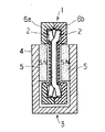
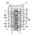
多相コイルを収容して冷媒を流通させて熱の除去を行なうコイルジャケットについては例えば特許文献1に開示されている。そのコイルジャケットについて図8〜10を用いて説明する。図8はリニアモータの構成を示す説明図である。図8のリニアモータは、固定子1側に多相コイル(以下、コイルと略す)2を配設し、可動子3側にヨーク4および永久磁石5を配したいわゆる可動磁石型のロングストロークタイプのリニアモータである。固定子1側には、第1および第2コイルジャケット(以下、ジャケットと略す)6a, 6bがホルダ7に固定された状態で配設されている。図9はコイルジャケットを構成する2つのジャケット部材のうちの一方のジャケット6bの正面図である。図10は図9のジャケット6bの断面図である。
【0005】
ジャケット6a,6bの対向する面(内面側)にはそれぞれコイル収容溝8a, 8bが設けられており、コイル2は図9に斜線にて示したような状態でジャケット6a,6b内に収容される。この場合、コイル収容溝8bの底面側には、図10(a)に示したような段部9が形成されており、コイル2は、図8に示したように段部9上にて支持された状態でコイル収容溝8a,8b内に収容され接着固定される。
【0006】
ジャケット6a,6bの内面側にはまた、冷媒を流通させるための流通路10a,10bが設けられている。この流通路10a,10bは、図9のA−A線の部分ではコイル2の内周側に位置する2本の通路として、また、図9のB−B線の部分ではコイル2の外周に接するように設けられた3本の通路として形成されている。また、前記段部9においてコイル2の外面とコイル収容溝8bの底面との間に形成された間隙11も冷媒の流通路として機能する。この場合、冷媒として、絶縁性の不活性流体であるフロリナートが用いられ、一方の冷媒流通口(図示省略)から供給されて他方の冷媒流通口(図示省略)から排出される。
【0007】
さらに、ジャケット6a, 6bの内面側には印籠嵌合部13a, 13bが設けられている。そして、これらを密に嵌合させた上でジャケット6a, 6bをネジ14によって固着することにより、コイル収容溝8a, 8bや流通路10a, 10bが密封状態となって冷媒の漏出が防止されるようになっている。そして、冷媒流通口から冷媒を供給し、これが流通路10a, 10bならびに間隙11を通り冷媒流通口に至ることにより、コイル2の周囲にまんべんなく冷媒がまわり、コイル2から発生した熱を効率よく排出することが可能となる。
【0008】
【特許文献1】
特開2000−004572号公報
【0009】
【発明が解決しようとする課題】
コイル2は通電により方向の異なる推力が絶えず生じるため、コイル収容溝8a, 8bの中で動こうとする。コイルが動くと永久磁石との位置関係が変化してしまうためモータの動作精度が低化する。これを防ぐためにコイル2とコイル収容溝8a,8bとの間のがたつきをできるだけ小さくし、かつ接着剤で固定している。そのため万一、冷媒により接着が剥がれてもコイル収容溝8a,8bに押さえられるためコイル2が大きくずれることは無い。また、コイル収容溝8a,8bは接着面にかかる推力負荷を低減する効果もある。更に、コイル収容溝8a,8bはコイル2の正確な位置決めをするのにも有効である。
【0010】
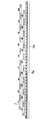
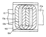
ところで、リニアモータの推力は磁気ギャップの磁束密度Bと単位磁石面積当りの導体長さlとの積に比例する。lを大きくして推力の向上を図る手段として空芯を有するコイルの空芯部に隣接するコイルの一部を配置して多相コイルを形成する方法がある。図7を用いて具体的に説明する。可動コイル60は、支持板100の両面に偏平コイルを設けて互いに連続した一組の偏平コイル60a、60b、60cを複数組設ける。各組の偏平コイルは、永久磁石20aに沿った磁気空隙路に沿って偏平コイルのコイル巾だけ順次ずらして配置する。そして、各組の偏平コイル60a、60b、60cは磁気空隙路内では同一平面上に配置され、磁気空隙路から外部に出た部分は互いに干渉しないように折り曲げる。
【0011】
このコイル巾だけ順次ずらして配置した多相コイルを図8〜10で説明した従来のコイルジャケット内に収容しようとすると、各コイルに空芯部が無いために多相コイル全体を溝内部に収容しなければならない。1コイルに着目すると通電しない時間があるため常に推力がかかるわけではないが、多相コイル全体が一体であるため、接着面には常に推力負荷がかかる。また、1コイル当りのコイルジャケットとの接触面積が小さくなる。これらのことから、特に水等の不活性でない冷媒を使うときの接着の信頼性は必ずしも十分とはいえない、という課題がある。また、多相コイル全体をジャケット内に収容しようとすると、もともとコイルそのものはバラバラなので、その固定、位置決めが極めて困難で、かつ推力発生方向に剛性が保てない、という課題がある。
【0012】
本発明の目的は、コイル巾だけ順次ずらして配置した多相コイルを収容して冷媒を流通させてもコイルとコイルジャケットとの接着に十分な信頼性が確保されるコイルジャケットを提供することにある。
本発明の目的は、多相コイルの固定、位置決めが容易で、かつ推力発生方向の剛性の高いコイルジャケットを提供することにある。
【0013】
【課題を解決するための手段】
本発明のコイルジャケットは、複数のコイルが実質的にコイル巾だけ磁気空隙路に沿って順次ずらされるとともに、各コイルが磁気空隙路内では同一平面上となるように配置されてなる多相コイルを収容するためのコイル収容溝を備えたコイルジャケットであって、各コイルを各々2つのコイル収容溝に収容できるようにしたことを特徴としている。
【0014】
本発明の可動子は、コイル収容溝を備えたコイルジャケットに、複数のコイルが実質的にコイル巾だけ磁気空隙路に沿って順次ずらされるとともに、各コイルが磁気空隙路内では同一平面上となるように配置されてなる多相コイルを収容してなる可動子であって、各コイルが各々2つのコイル収容溝に収容されることを特徴としている。
【0015】
本発明の固定子は、コイル収容溝を備えたコイルジャケットに、複数のコイルが実質的にコイル巾だけ磁気空隙路に沿って順次ずらされるとともに、各コイルが磁気空隙路内では同一平面上となるように配置されてなる多相コイルを収容してなる固定子であって、各コイルが各々2つのコイル収容溝に収容されることを特徴としている。
【0016】
本発明の可動子はその多相コイルが永久磁石列の形成する磁気空隙路内に位置するように、永久磁石列と組み合わせることにより可動コイル型のリニアモータを作製することができる。
【0017】
本発明の固定子はその多相コイルが永久磁石列の形成する磁気空隙路内に位置するように、永久磁石列と組み合わせることにより可動磁石型のリニアモータを作製することができる。
【0018】
【発明の実施の形態】
以下、本発明の実施の形態を図面に基づいて詳細に説明する。図1は本発明の一実施の形態であるリニアモータの構成を示す説明図である。図1のリニアモータは、可動子1側に多相コイル(以下、コイルと略す)2を配設し、固定子3側にヨーク4および永久磁石5を配したいわゆる可動コイル型のロングストロークタイプのリニアモータである。多相コイルを形成する各コイルは永久磁石5の表面近傍またはそれらの間に形成される磁気空隙路内では同一平面上となるように配置される。図6(a)に示すようにコイル2は自己融着線を巻いて作製した空芯部を有する扁平コイルである。全体に長方形であり長辺をなす部分が磁気空隙路内で同一平面上となるように配置される。このとき隣接するコイルの長辺が空芯部内に配置される。図6(b)に示すように短辺部分は干渉を防ぐために折り曲げる。なお、図1で可動子1は紙面に対し垂直方向へ移動自在に案内される。
【0019】
可動子1側には、コイル2を収容し冷却液を流す流路を有する第1および第2コイルジャケット(以下、ジャケットと略す)6a,6bが配設されている。ジャケット6a,6bは、合成樹脂をシート状の部材に含浸させて積層し押圧して形成された積層材によって形成された部材であり板状に加工されている。この積層材として、強度や耐熱性を考慮して、エポキシ樹脂を含浸させたガラス布を積層させてプレス成形した積層材を用いている。もちろんこれ以外の合成樹脂を使うこともできる。
【0020】
図2は可動子1の正面図およびその右側面図である。可動子1はジャケット6a,6bでコイル2を挟持しボルト6cで締結する構造である。冷却液は入口6dから入り出口6eから排出する。冷却液の供給管と固定子3との干渉を防ぐために入口6dと入り出口6eは固定子3に対して反対側に位置させる。
【0021】
図3は図2のA−A断面図、図4は図2のB−B断面の一部拡大図である。ジャケット6aの対向する面(内面側)にはコイル収容溝8aが形成されており、コイル2は図示した状態でジャケット6a内に収容される。他のコイルはここでは図示を省略している。この場合、コイル収容溝8aの底面側には、図4に示したような段部9が形成されており、コイル2は段部9上にて支持された状態でコイル収容溝8a,8b内に収容され接着固定される。コイル収容溝8a,8bを形成する仕切り12の機能はコイル2とジャケット6aとを互いに接着して一体構造としてモールド品と同等の剛性を可動子または固定子に与えることである。別の機能は、コイルの冷却を可能とすることである。別の機能は、位相を合わせるための正確なコイル2の位置決めが出来ることである。仕切り12の位置は機械加工精度で決まるためかなり正確である。コイルの寸法精度はそれに比べると高くない。ましてや複数のコイルを互いに密着させて配置すると誤差が蓄積されて大きな誤差となる。各コイルを仕切り12により位置決めすることでコイル2の正確な位置決めが出来る。別の機能は、コイルの推力を受け止め接着面が受ける推力負荷を低減することである。その結果、冷却液で直接にコイル2を冷却するにもかかわらず接着面の高い信頼性を確保することができる。
【0022】
冷媒を流通させるための流通路は、コイル2の折り曲げ部を内包し図2の冷却液入口6dと出口6eとを結ぶ流路、それと平行に形成されコイル2の反対側の折り曲げ部を内包する流路および段部9とコイル2との間の間隙11によって形成される。この2つの流路は間隙11を介して互いに繋がっているため入口6dから入った冷却液は上記流路および間隙11を流れながらコイル2を冷却し出口6eから排出される。この場合、冷媒として、絶縁性の不活性流体であるフロリナートを好適に用いることができる。コイル2に安定した絶縁被膜を形成することにより冷却効果のより大きい水などの冷媒を使うことも可能である。
【0023】
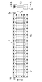
図5に実施例におけるコイル2の重ね方を示す。空芯部に両隣のコイルが入り込み全体として同一平面を形成する。各コイルは各コイルのコイル巾に対応した寸法を有する2つのコイル収容溝8aに収容される。コイル2の重ね方は図7に示すものであっても良い。
【0024】
【発明の効果】
本願のコイルジャケットにより、コイル巾だけ順次ずらして配置した多相コイルを収容して冷媒を流通させてもコイルとコイルジャケットとの接着に十分な信頼性が確保することができる。また、多相コイルの固定、位置決めが容易で、かつ推力発生方向の剛性の高いコイルジャケットを提供することができる。
【図面の簡単な説明】
【図1】図1は本発明の一実施の形態であるリニアモータの構成を示す説明図である。
【図2】本発明によるリニアモータにて用いられる可動子の正面図およびその右側面図である。
【図3】図2のA−A断面図である。
【図4】図2のB−B断面の一部拡大図である。
【図5】コイルの重ね方の一例を示す図である。
【図6】本発明に用いることのできるコイルの正面図(a)と側面図(b)である。
【図7】複数のコイルが実質的にコイル巾だけ磁気空隙路に沿って順次ずらされるとともに、各コイルが磁気空隙路内では同一平面上となるように配置されてなる多相コイルの一例を示す説明図である。
【図8】従来のリニアモータの構成を示す説明図である。
【図9】コイルジャケットを構成する2つのジャケット部材のうちの一方のジャケットの正面図である。
【図10】図9のジャケットの断面図である。
【符号の説明】
1 可動子
2 コイル
3 固定子
4 ヨーク
5 永久磁石
6a,6b ジャケット
6d 冷却液入口
6e 冷却液出口
8a,8b コイル収容溝
9 段部
11 間隙
12 仕切り[0001]
TECHNICAL FIELD OF THE INVENTION
The present invention relates to a linear motor, and more particularly to a technique that is effective when applied to a coil jacket that accommodates an armature coil and circulates a refrigerant to remove heat.
[0002]
[Prior art]
2. Description of the Related Art Conventionally, a linear motor in which a permanent magnet and an armature coil (polyphase coil) are relatively linearly movable has been used as a kind of an electric motor in a linear driving device such as a semiconductor manufacturing apparatus or an XY plotter. Widely used as.
[0003]
Here, the multi-phase coil is usually arranged in a state of being fixedly supported by a coil jacket which is a coil support member. In this case, the coil jacket is composed of two divided members, and the multi-phase coil is accommodated between the two members. In addition, a cooling passage is provided in the coil jacket, and an inert refrigerant such as florinate is caused to flow therethrough at a pressure of about 3 kg / cm 2 , thereby removing the influence of heat generated from the coil. There is also. In particular, linear motors having such a cooling structure are often used for positioning a mover with high accuracy by a laser interferometer or the like, such as a stepper in a semiconductor manufacturing apparatus.
[0004]
A coil jacket that accommodates a multi-phase coil and removes heat by circulating a refrigerant is disclosed in, for example, Patent Document 1. The coil jacket will be described with reference to FIGS. FIG. 8 is an explanatory diagram showing the configuration of the linear motor. The linear motor shown in FIG. 8 has a so-called movable magnet type long stroke type in which a polyphase coil (hereinafter abbreviated as a coil) 2 is disposed on a stator 1 side, and a yoke 4 and a permanent magnet 5 are disposed on a mover 3 side. Linear motor. On the stator 1 side, first and second coil jackets (hereinafter abbreviated as jackets) 6a and 6b are provided in a state fixed to a holder 7. FIG. 9 is a front view of one of the jacket members 6b constituting the coil jacket. FIG. 10 is a sectional view of the jacket 6b of FIG.
[0005]
On opposite surfaces (inner surfaces) of the jackets 6a and 6b, coil accommodating grooves 8a and 8b are provided, respectively, and the coil 2 is accommodated in the jackets 6a and 6b in a state shown by oblique lines in FIG. You. In this case, a step 9 as shown in FIG. 10A is formed on the bottom side of the coil accommodating groove 8b, and the coil 2 is supported on the step 9 as shown in FIG. In this state, the coils are accommodated in the coil accommodating grooves 8a and 8b, and are adhered and fixed.
[0006]
The inner surfaces of the jackets 6a and 6b are also provided with flow passages 10a and 10b for flowing the refrigerant. These flow passages 10a and 10b are two passages located on the inner peripheral side of the coil 2 in the portion along the line AA in FIG. 9 and on the outer periphery of the coil 2 in the portion along the line BB in FIG. It is formed as three passages provided so as to be in contact with each other. Further, the gap 11 formed between the outer surface of the coil 2 and the bottom surface of the coil housing groove 8b in the step portion 9 also functions as a refrigerant passage. In this case, fluorinert, which is an insulating inert fluid, is used as the refrigerant, and is supplied from one refrigerant distribution port (not shown) and discharged from the other refrigerant distribution port (not shown).
[0007]
Further, on the inner surface side of the jackets 6a and 6b, there are provided iris fitting portions 13a and 13b. The jackets 6a and 6b are tightly fitted and then fixed by screws 14, so that the coil accommodating grooves 8a and 8b and the flow passages 10a and 10b are in a sealed state, thereby preventing refrigerant from leaking. It has become. Then, the refrigerant is supplied from the refrigerant distribution port, and the refrigerant flows through the flow paths 10a and 10b and the gap 11 to reach the refrigerant distribution port. It is possible to do.
[0008]
[Patent Document 1]
JP 2000-004572 A
[Problems to be solved by the invention]
The coil 2 constantly moves in the coil accommodating grooves 8a and 8b because thrusts in different directions are constantly generated by energization. When the coil moves, the positional relationship with the permanent magnet changes, so that the operating accuracy of the motor decreases. In order to prevent this, the play between the coil 2 and the coil accommodating grooves 8a and 8b is reduced as much as possible and is fixed with an adhesive. Therefore, even if the adhesive is peeled off by the refrigerant, the coil 2 is not largely displaced because it is pressed by the coil accommodating grooves 8a and 8b. The coil accommodating grooves 8a and 8b also have the effect of reducing the thrust load applied to the bonding surface. Further, the coil accommodating grooves 8a and 8b are effective in accurately positioning the coil 2.
[0010]
Incidentally, the thrust of the linear motor is proportional to the product of the magnetic flux density B of the magnetic gap and the conductor length l per unit magnet area. As a means for improving the thrust by increasing l, there is a method of forming a polyphase coil by arranging a part of the coil adjacent to the air core of the coil having the air core. This will be specifically described with reference to FIG. The movable coil 60 is provided with flat coils on both sides of the support plate 100, and a plurality of sets of flat coils 60a, 60b, and 60c continuous with each other are provided. The flat coils of each set are sequentially shifted by the coil width of the flat coils along the magnetic air gap along the permanent magnet 20a. The flat coils 60a, 60b, and 60c of each set are arranged on the same plane in the magnetic air gap, and the portions that come out of the magnetic air gap are bent so as not to interfere with each other.
[0011]
If it is attempted to accommodate the polyphase coils which are sequentially shifted by the coil width in the conventional coil jacket described with reference to FIGS. 8 to 10, the entire polyphase coil is accommodated in the groove because each coil has no air core. Must. Paying attention to one coil, thrust is not always applied because there is a time during which power is not supplied. However, since the entire multiphase coil is integrated, a thrust load is always applied to the bonding surface. Also, the contact area with the coil jacket per coil is reduced. For these reasons, there is a problem that the reliability of adhesion is not always sufficient especially when a non-inert refrigerant such as water is used. Further, if the entire multi-phase coil is to be accommodated in the jacket, the coil itself is originally disjointed, so that it is extremely difficult to fix and position the coil and to maintain rigidity in the thrust generating direction.
[0012]
An object of the present invention is to provide a coil jacket in which a multi-phase coil which is sequentially shifted by a coil width is accommodated and sufficient reliability is ensured for adhesion between the coil and the coil jacket even when a refrigerant is circulated. is there.
An object of the present invention is to provide a coil jacket that can easily fix and position a polyphase coil and has high rigidity in a thrust generating direction.
[0013]
[Means for Solving the Problems]
A coil jacket according to the present invention is a multi-phase coil in which a plurality of coils are sequentially shifted along a magnetic gap substantially by a coil width, and each coil is arranged so as to be on the same plane in the magnetic gap. And a coil jacket provided with a coil accommodating groove for accommodating each coil, wherein each coil can be accommodated in two coil accommodating grooves.
[0014]
In the mover of the present invention, a plurality of coils are sequentially shifted along a magnetic gap path substantially by a coil width in a coil jacket provided with a coil receiving groove, and each coil is positioned on the same plane in the magnetic gap path. A mover accommodating a multi-phase coil arranged so that each coil is accommodated in two coil accommodating grooves.
[0015]
In the stator of the present invention, the plurality of coils are sequentially shifted along the magnetic gap path substantially by the coil width in the coil jacket having the coil receiving groove, and each coil is coplanar in the magnetic gap path. A stator comprising multi-phase coils arranged such that each coil is accommodated in two coil accommodation grooves.
[0016]
The mover of the present invention can produce a moving coil type linear motor by combining with the permanent magnet array so that the multi-phase coil is located in the magnetic air gap formed by the permanent magnet array.
[0017]
The stator of the present invention can produce a movable magnet type linear motor by combining with a permanent magnet array so that its polyphase coil is located in a magnetic air gap formed by the permanent magnet array.
[0018]
BEST MODE FOR CARRYING OUT THE INVENTION
Hereinafter, embodiments of the present invention will be described in detail with reference to the drawings. FIG. 1 is an explanatory diagram showing a configuration of a linear motor according to one embodiment of the present invention. The linear motor shown in FIG. 1 has a so-called moving coil type long stroke type in which a multi-phase coil (hereinafter abbreviated as a coil) 2 is disposed on a mover 1 side and a yoke 4 and a permanent magnet 5 are disposed on a stator 3 side. Linear motor. The coils forming the multi-phase coil are arranged on the same plane near the surface of the permanent magnet 5 or in a magnetic air gap formed therebetween. As shown in FIG. 6A, the coil 2 is a flat coil having an air core portion formed by winding a self-fusing wire. The whole rectangular shape and the long sides are arranged so as to be flush with each other in the magnetic air gap. At this time, the long sides of the adjacent coils are arranged in the air core. As shown in FIG. 6B, the short side is bent to prevent interference. In FIG. 1, the mover 1 is guided movably in a direction perpendicular to the plane of the drawing.
[0019]
On the mover 1 side, first and second coil jackets (hereinafter abbreviated as jackets) 6a and 6b having a flow path for accommodating the coil 2 and flowing the cooling liquid are provided. The jackets 6a and 6b are members made of a laminated material formed by impregnating a synthetic resin into a sheet-like member, laminating and pressing, and are processed into a plate shape. In consideration of strength and heat resistance, a laminated material obtained by laminating glass cloth impregnated with an epoxy resin and press-molding the laminated material is used as the laminated material. Of course, other synthetic resins can be used.
[0020]
FIG. 2 is a front view of the mover 1 and a right side view thereof. The mover 1 has a structure in which the coil 2 is sandwiched between jackets 6a and 6b and fastened with bolts 6c. The cooling liquid enters and exits from the inlet 6d and the outlet 6e. In order to prevent interference between the coolant supply pipe and the stator 3, the inlet 6 d and the inlet / outlet 6 e are located on opposite sides of the stator 3.
[0021]
FIG. 3 is a cross-sectional view taken along the line AA of FIG. 2, and FIG. A coil accommodating groove 8a is formed on the facing surface (inner surface side) of the jacket 6a, and the coil 2 is accommodated in the jacket 6a in the illustrated state. The other coils are not shown here. In this case, a step 9 as shown in FIG. 4 is formed on the bottom side of the coil housing groove 8a, and the coil 2 is supported on the step 9 in the coil housing grooves 8a and 8b. It is housed and fixed by adhesive. The function of the partition 12 for forming the coil accommodating grooves 8a and 8b is to bond the coil 2 and the jacket 6a to each other to give the movable member or the stator the same rigidity as a molded product as an integrated structure. Another function is to allow cooling of the coil. Another function is to be able to accurately position the coil 2 to match the phases. Since the position of the partition 12 is determined by the machining accuracy, it is quite accurate. The dimensional accuracy of the coil is not so high. Furthermore, when a plurality of coils are arranged in close contact with each other, errors accumulate and become large errors. By positioning each coil by the partition 12, the coil 2 can be accurately positioned. Another function is to receive the thrust of the coil and reduce the thrust load on the adhesive surface. As a result, high reliability of the bonding surface can be ensured even though the coil 2 is directly cooled by the cooling liquid.
[0022]
The flow passage for flowing the refrigerant includes the bent portion of the coil 2 and connects the coolant inlet 6d and the outlet 6e in FIG. 2 and the bent portion formed in parallel with the opposite side of the coil 2. It is formed by a gap 11 between the flow path and the step 9 and the coil 2. Since these two flow paths are connected to each other via the gap 11, the coolant entering from the inlet 6 d cools the coil 2 while flowing through the flow path and the gap 11, and is discharged from the outlet 6 e. In this case, Florinert, which is an insulating inert fluid, can be suitably used as the refrigerant. By forming a stable insulating film on the coil 2, it is also possible to use a refrigerant such as water having a greater cooling effect.
[0023]
FIG. 5 shows how the coils 2 are overlapped in the embodiment. The coils adjacent to both sides enter the air core portion and form the same plane as a whole. Each coil is accommodated in two coil accommodation grooves 8a having dimensions corresponding to the coil width of each coil. The method of stacking the coils 2 may be as shown in FIG.
[0024]
【The invention's effect】
According to the coil jacket of the present invention, sufficient reliability for bonding the coil and the coil jacket can be ensured even when the refrigerant is circulated while accommodating the multi-phase coils which are sequentially shifted by the coil width. Further, it is possible to provide a coil jacket that can easily fix and position the polyphase coil and has high rigidity in the thrust generating direction.
[Brief description of the drawings]
FIG. 1 is an explanatory diagram showing a configuration of a linear motor according to an embodiment of the present invention.
FIG. 2 is a front view and a right side view of a mover used in the linear motor according to the present invention.
FIG. 3 is a sectional view taken along line AA of FIG. 2;
FIG. 4 is a partially enlarged view of a BB section of FIG. 2;
FIG. 5 is a diagram illustrating an example of a method of stacking coils.
FIG. 6 is a front view (a) and a side view (b) of a coil that can be used in the present invention.
FIG. 7 shows an example of a multi-phase coil in which a plurality of coils are sequentially shifted along a magnetic air gap substantially by a coil width, and each coil is arranged so as to be on the same plane in the magnetic air gap. FIG.
FIG. 8 is an explanatory diagram showing a configuration of a conventional linear motor.
FIG. 9 is a front view of one of two jacket members constituting the coil jacket.
FIG. 10 is a sectional view of the jacket of FIG. 9;
[Explanation of symbols]
DESCRIPTION OF SYMBOLS 1 Mover 2 Coil 3 Stator 4 Yoke 5 Permanent magnet 6a, 6b Jacket 6d Coolant inlet 6e Coolant outlet 8a, 8b Coil accommodation groove 9 Step 11 Gap 12 Partition