【0001】
【発明の属する技術分野】
本発明は、電気化学デバイスの製造方法に関するものである。
【0002】
【従来の技術】
アノード電極と、カソード電極と、高分子固体電解質によって形成されたイオン交換膜とからなるMEA(Membrane & Electrode Assembly)を有し、アルコール水溶液等を燃料とする電気化学装置では現在、ナフィオン(登録商標)(パーフルオロスルホン酸樹脂(DoPont社製のNafion(R)など))のような高いイオン伝導性を持つモノマーが、イオン交換膜及び電極内バインダーとして用いられている(例えば、特許文献1及び特許文献2参照。)。
【0003】
一方、燃料としては、メタノールが主に使用されている。また、他に水素ガス、エタノール、ジメチルエーテル(DME)、ジエチルエーテル(DEE)等の有機物の研究例もある(例えば、特許文献3参照。)。
【0004】
これらの中でも、燃料としてメタノール水溶液を用い、アノード電極で直接反応させるダイレクトメタノール燃料電池(DMFC)は、高エネルギー密度が実現されるため、小型携帯燃料電池等で次世代電源としての期待が高まっている。
【0005】
【特許文献1】
特開昭61−67787号公報、第11欄16行目〜第15欄7行目
【特許文献2】
特開昭61−67788号公報、第12欄9行目〜第16欄2行目
【特許文献3】
特公平3−208260号公報、第3頁右下欄1行目〜16行目、第1図
【0006】
【発明が解決しようとする課題】
しかしながら、上述したようなダイレクトメタノール燃料電池等の電気化学装置では、更なる出力効率及びその耐久性の向上が望まれている。特に、耐久性においては、熱的耐久性、化学的耐久性、強度的耐久性の全てにおいて、上記のダイレクトメタノール燃料電池は、水素系燃料電池と比べて不利な環境にある。
【0007】
即ち、上記したナフィオン(登録商標)等の従来のスルホン化フッ素系高分子は、アルコール燃料に溶解する問題があり、このために、触媒粒子の結着力が弱くなり、結果として触媒粒子の遊離、出力劣化を及ぼすからである。また、この溶解現象は触媒層の剥離に加え、MEA膜強度の低下やMEA膜の破断等も引き起こす。
【0008】
従って、電極内結着剤及びイオン交換膜(高分子固体電解質膜)の材料としては、アルコール燃料に溶解し難い材質であると共に、プロトン伝導性は高くなければならない。
【0009】
本発明は、上述したような問題点を解決するためになされたものであって、その目的は、出力効率の向上を図ることができ、また熱的耐久性、化学的耐久性及び強度的耐久性等の耐久性に優れた電気化学デバイスを得ることができる、電気化学デバイスの製造方法を提供することにある。
【0010】
【課題を解決するための手段】
即ち、本発明は、第1極と、第2極と、これらの電極間に挟持されたイオン交換膜とから構成される電気化学デバイスの製造方法であって、
触媒物質とポリフッ化ビニリデンとを含む触媒層を形成した後、この触媒層の前記ポリフッ化ビニリデンにイオン交換基を結合し、得られたイオン交換基含有の触媒層を前記第1極及び前記第2極の少なくとも一方に用いる、
電気化学デバイスの製造方法に係るものである。
【0011】
本発明によれば、前記触媒物質と、メタノールや水への溶解性を有さないポリフッ化ビニリデンとを含む前記触媒層を形成した後、この触媒層の前記ポリフッ化ビニリデンに前記イオン交換基を結合し、得られたイオン交換基含有の触媒層を前記第1極及び前記第2極の少なくとも一方に用いるので、前記触媒物質への前記ポリフッ化ビニリデンの結着力は強く、経時出力劣化特性に優れた電気化学デバイスを製造することができ、更に前記触媒層の形成後に前記イオン交換基を結合させているために、目的とする触媒層自体を形成し易くなる。これに反し、従来のナフィオン(登録商標)等のスルホン化フッ素系高分子はアルコール燃料に溶解する問題を有し、このスルホン化フッ素系高分子を用いた電気化学デバイスは触媒物質の遊離や出力劣化を生じる。
【0012】
また、前記ポリフッ化ビニリデンはメタノール水溶液にも不溶であるので、例えばダイレクトメタノール燃料電池等の電気化学装置として構成しても、上記した従来例のように、使用中に前記触媒層が剥離することはなく、また前記第1極と、前記第2極と、前記イオン交換膜とから構成されるMEA(Membrane & Electrode Assembly)膜の破断を防止することができる。
【0013】
従って、出力効率の向上を図ることができ、また熱的耐久性、化学的耐久性及び強度的耐久性等の耐久性に優れた電気化学デバイスを作製することができる。
【0014】
【発明の実施の形態】
本発明の電気化学デバイスの製造方法は、前記触媒物質と前記ポリフッ化ビニリデン(PVDF)とを含む前記触媒層を形成した後、この触媒層の前記ポリフッ化ビニリデンに前記イオン交換基を結合することが特徴的であり、前記イオン交換基含有の触媒層を前記第1極及び前記第2極の少なくとも一方に用いればよいが、特に、前記触媒層と、ポリフッ化ビニリデンからなるイオン交換膜前駆体とを接合した後、この接合体を前記イオン交換基含有の化合物と接触させ、前記接合体中の前記ポリフッ化ビニリデンに前記イオン交換基を置換導入することが望ましい。
【0015】
具体的には、図1に本発明に基づく電気化学デバイスの製造方法の一例の概略断面図を示すように、まず、白金等の前記触媒物質と前記ポリフッ化ビニリデンとを含む触媒層1aと、ポリフッ化ビニリデンからなるイオン交換膜前駆体2aとを接合し、MEA膜となる接合体3を形成する。即ち、接合体3は、前記第1極としての集電体4と、触媒層1aと、イオン交換膜前駆体2aと、触媒層1aと、前記第2極としての集電体4とが積層してなる。
【0016】
次に、この接合体3を前記イオン交換基含有の化合物の溶液に浸漬し、加圧及び加熱することによって、前記化合物を触媒層1a及びイオン交換膜前駆体2a中に含浸させ、これらを形成する前記ポリフッ化ビニリデン中のフッ素原子に対して前記イオン交換基をそれぞれ置換導入する。この場合の処理条件としては、接合体3の層厚及び組成等によって異なるが、溶液濃度5〜10mol/l、浸漬時の圧力202650〜303975Pa、温度120〜140℃、浸漬時間60〜600minとするのがよい。
【0017】
これによって、図示するように、前記イオン交換基含有の前記ポリフッ化ビニリデン及び前記触媒物質からなる触媒層1bと、前記イオン交換基を有する前記ポリフッ化ビニリデンからなるイオン交換膜2bと、集電体4とからなるMEA膜5を容易に作製することができる。
【0018】
なお、前記ポリフッ化ビニリデンの分子量は重量平均分子量で1.0×10⁵〜1.0×10⁶であるのが望ましい。
【0019】
また、前記イオン交換基としては、スルホン酸基(−SO3H)、カルボキシル基(−COOH)、燐酸基(−PO3H)、直鎖スルホン基(−(CH2)nSO3H(nは整数))、ペルフルオロカーボン直鎖スルホン基(−(CF2)nSO3H(nは整数))等を挙げることができる。また、そのイオン交換容量(IEC)は0.9〜2.0meq/gとするのがよく、0.9〜1.2meq/gが更に望ましいが、こうした濃度は上記溶液の濃度のコントロールによって定量的にかつ容易に制御することができる。
【0020】
また、前記触媒物質としては、白金、ルテニウム、パラジウム、ケイ素、炭素、アルミニウム、マグネシウム、コバルト、鉄、ニッケル、モリブデン、タングステン等の従来公知のものがいずれも使用可能であり、その添加量は0.15〜1.0g/触媒量g、面積担持密度は0.1〜2.0mg/cm2(但し、Pt等の重量とする。)、触媒粒径は1〜20nmとするのがよい。さらに、前記第1極及び前記第2極としての集電体4は、カーボン等の従来公知のものがいずれも使用可能である。
【0021】
本発明に基づく電気化学デバイスの製造方法によれば、メタノールや水に溶けない前記ポリフッ化ビニリデン及び前記触媒物質を含む触媒層1aと、ポリフッ化ビニリデンからなるイオン交換膜前駆体2aとを接合した後、この接合体3を前記イオン交換基含有の化合物の溶液に浸漬し、加圧及び加熱することによって、触媒層1a及びイオン交換膜前駆体2aを形成する前記ポリフッ化ビニリデンに前記イオン交換基をそれぞれ置換導入するので、前記触媒物質の結着力が強く、経時出力劣化率が低い電気化学デバイスを製造することができる。
【0022】
また、上述したように前記ポリフッ化ビニリデンはメタノール水溶液にも不溶であるので、例えば得られたMEA膜5をダイレクトメタノール燃料電池等の電気化学デバイスとして構成しても、使用中に触媒層1bが剥離することはなく、またMEA膜5の破断を防止することができる。
【0023】
従って、出力効率のより一層の向上を図ることができ、また熱的耐久性、化学的耐久性及び強度的耐久性等の耐久性に一層優れた電気化学デバイスを作製することができる。
【0024】
本発明に基づく電気化学デバイスの製造方法は、前記電気化学デバイスとして燃料電池を製造することが好ましい。
【0025】
図2は、本発明に基づく製造方法によって得られた前記電気化学デバイスとしての燃料電池の概略断面図である。
【0026】
この燃料電池は、互いに対向する、端子6付きの負極(燃料極又は水素極)7、及び端子8付きの正極(酸素極)9を有し、これらの両極間に電解質として使用することができるイオン交換膜2が挟着されている。また、負極7及び正極9はそれぞれ、触媒層1を有している。
【0027】
負極7、正極9及びイオン交換膜2からなる多層膜(MEA)は、本発明に基づく電気化学デバイスの製造方法によって作製することができる。
【0028】
即ち、まず、白金等の前記触媒物質と前記ポリフッ化ビニリデンとを含む触媒層を、負極7及び正極9としての集電体(例えばカーボンシート)上にそれぞれ形成する。そして、触媒層付きの負極7及び正極9の間に、触媒層と接するようにして、ポリフッ化ビニリデンからなる前記イオン交換膜前駆体を挟持させて、接合する。
【0029】
次に、得られた接合体を前記イオン交換基含有の化合物の溶液に浸漬し、加圧及び加熱することによって、前記触媒層及び前記イオン交換膜前駆体を形成する前記ポリフッ化ビニリデンに前記イオン交換基をそれぞれ置換導入することができる。これにより、イオン交換膜2と電極7、9とからなる前記多層膜(MEA膜)を作製することができる。
【0030】
この燃料電池のメカニズムは、使用時には、負極7側ではメタノール水溶液流路10中にメタノール水溶液が通される。燃料(メタノール)が流路10を通過する間に水素イオンを発生し、この水素イオンは負極7で発生した水素イオン及びイオン交換膜2で発生した水素イオンと共に正極9側へ移動し、そこでO2流路11を通る酸素(空気)と反応し、これにより所望の起電力が取り出される。
【0031】
ここで、触媒層1付きの負極7、イオン交換膜2及び触媒層1付きの正極9からなるMEA膜が複数個積層されて一体構造に形成されていてもよく、この場合は、より高い起電力を容易に得られるという効果がある。また、燃料としてメタノール水溶液を用いる例を説明したが、流路10中に水素ガス等を通してもよい。
【0032】
かかる燃料電池は、メタノールや水に溶けない前記ポリフッ化ビニリデン及び前記触媒物質を含む前記触媒層と、ポリフッ化ビニリデンからなる前記イオン交換膜前駆体とを接合した後、この接合体を前記イオン交換基含有の化合物の溶液に浸漬し、加圧及び加熱することによって、前記触媒層及び前記イオン交換膜前駆体を形成する前記ポリフッ化ビニリデンに前記イオン交換基をそれぞれ置換導入するので、前記触媒物質の結着力が強く、かつ経時出力劣化率が低い。
【0033】
また、上述したように前記ポリフッ化ビニリデンはメタノール水溶液にも不溶であるので、ダイレクトメタノール燃料電池に適用しても、使用中に触媒層1が剥離することはなく、またMEA膜の破断を防止することができる。
【0034】
従って、出力効率のより一層の向上を図ることができ、また耐久性により一層優れている。
【0035】
上記に前記電気化学デバイスとして燃料電池を製造する例を説明したが、この他にも、前記電気化学デバイスとして、燃料電池とは逆の反応メカニズムによる水素製造装置を製造してもよい。また、リチウムイオン伝導性固体電解質を使用したリチウム電池、プロトン伝導性固体電解質を使用した水電解装置、或いはプロトンポンプ等に利用し得る。
【0036】
また、図1に示すように、接合体3を形成した後、この接合体3を前記イオン交換基含有の化合物の溶液に浸漬し、接合体3中のポリフッ化ビニリデンに前記イオン交換基を置換導入して、前記イオン交換基含有の触媒層1bと、イオン交換膜2bと、集電体4とからなるMEA膜5を作製する例を説明したが、本発明に基づく電気化学デバイスの製造方法は、イオン交換基含有の触媒層1bを前記第1極及び前記第2極の少なくとも一方に用いればよい。
【0037】
さらに、前記電極間に挟持されたイオン交換膜2bは、ナフィオン(登録商標)(パーフルオロスルホン酸)、非フルオロカーボンスルホン酸、部分フッ化カーボンスルホン酸、パーフルオロカルボン酸、非フルオロカーボンカルボン酸、部分フッ化カーボンカルボン酸、パーフルオロリン酸、非フルオロカーボンリン酸、部分フッ化カーボンリン酸等であってもよい。この場合、他方の触媒層にはナフィオン(登録商標)等の他の高分子化合物を用いてよい。或いは、触媒層1bを上記した浸漬処理後に、別途作製したイオン交換膜と接合してもよい。
【0038】
【実施例】
以下、本発明に基づく電気化学デバイスの製造方法の実施例について説明する。
【0039】
実施例1
分子量150000のポリフッ化ビニリデン(PVDF;アルドリッチ社製)をNMP(1−メチル−2−ピロリドン)に溶解した溶液を作製した。
【0040】
この溶液にPVDF:Pt−Ru/C=0.6:1.0となるように燃料電池用触媒(田中貴金属社製)を加え、24時間攪拌することによってアノード触媒分散液を作製した。なお、燃料電池用触媒はPt:Ru:C=23:22:55(重量比)であった。また、上記と同様にしてPt:C=0.46:0.54(重量比)の触媒(田中貴金属社製)を用いてカソード触媒分散液を作製した。
【0041】
一方、PVDF溶液のみを膜厚20μmのポリイミド膜にキャストし、NMPを約40℃で常湿下乾燥させ、約50μmの膜厚のPVDF膜を得た。
【0042】
次に、上記に得られたアノード触媒分散液及びカソード触媒分散液をそれぞれカーボンシート(エレクトロケミカル社製)に塗布し、乾燥させることによって、カソード電極(触媒担持密度:1.0mg−Pt/cm2)、アノード電極(触媒担持密度:1.0mg−Pt/cm2)を作製した。
【0043】
次に、上記に得られた両極を先述のPVDF膜の両面に重ね、約30kgf/cm2で100℃にしながら、5分〜10分間ホットプレスし、処理前MEAを作製した。
【0044】
そして、上記に得られた処理前MEAをメタンスルホン酸水溶液(1M)に浸し、オートクレーブ中で202650Pa(2気圧)で130℃に加熱することで、処理前MEA中のPVDFをメタンスルホン化したMEA(以下、処理後MEAと称することがある。)を得た。処理後MEAは純水で洗浄後、余分なメタンスルホン酸を除去し、下記の燃料電池測定に供した。
【0045】
燃料電池測定条件
酸素極ガス:湿度100%、40℃、大気、100ml/分
燃料極燃料:1M MeOH水溶液、40℃、還流無し
発電条件:0.3V連続発電、t=0時の電流密度、5分おきの電流密度を測定(気温22℃、相対湿度51%RH)。
【0046】
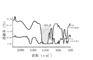
ここで、処理前MEA及び処理後MEAについてのIRスペクトルを図3に併せて示すように、処理後MEAは、処理前MEA中のPVDFにスルホン酸基(−SO3H)が置換導入されていることが分かった。
【0047】
比較例1
電解質膜(イオン交換膜)として実施例1と同じ膜厚のナフィオン112(登録商標)を用い、また実施例1のPVDFをナフィオン(登録商標)(フルウチ化学、EW1100、SE20192)に置き換えたアノード電極及びカソード電極を作製した以外は、実施例1と同様にしてMEAを形成し、燃料電池測定を行った。
【0048】
図4に実施例1と比較例1の出力曲線(経時変化)を示す。
【0049】
図4より明らかなように、本発明に基づく電気化学デバイス(燃料電池)の製造方法によれば、メタノールや水に溶けない前記ポリフッ化ビニリデン及び前記触媒物質を含む前記触媒層と、ポリフッ化ビニリデンからなる前記イオン交換膜前駆体とを接合した後、この接合体を前記イオン交換基含有の化合物の溶液(例えばメタンスルホン酸水溶液)に浸漬し、加圧及び加熱することによって、前記触媒層及び前記イオン交換膜前駆体を形成する前記ポリフッ化ビニリデンに前記イオン交換基(例えばスルホン酸基)をそれぞれ置換導入するので、前記触媒物質の結着力が強く、経時出力劣化率が低い電気化学デバイスを製造することができた。
【0050】
また、上述したように前記ポリフッ化ビニリデンはメタノール水溶液に不溶であるので、ダイレクトメタノール燃料電池に適用しても、使用中に前記触媒層が剥離することはなく、またMEA膜の破断を防止することができた。
【0051】
従って、出力効率のより一層の向上を図ることができ、また耐久性により一層優れた燃料電池を作製することができた。
【0052】
【発明の作用効果】
本発明によれば、前記触媒物質と、メタノールや水への溶解性を有さないポリフッ化ビニリデンとを含む前記触媒層を形成した後、この触媒層の前記ポリフッ化ビニリデンに前記イオン交換基を結合し、得られたイオン交換基含有の触媒層を前記第1極及び前記第2極の少なくとも一方に用いるので、前記触媒物質への前記ポリフッ化ビニリデンの結着力は強く、経時出力劣化特性に優れた電気化学デバイスを製造することができ、更に前記触媒層の形成後に前記イオン交換基を結合させているために、目的とする触媒層自体を形成し易くなる。
【0053】
また、前記ポリフッ化ビニリデンはメタノール水溶液にも不溶であるので、例えばダイレクトメタノール燃料電池等の電気化学装置として構成しても、使用中に前記触媒層が剥離することはなく、また前記第1極と、前記第2極と、前記イオン交換膜とから構成されるMEA(Membrane & Electrode Assembly)膜の破断を防止することができる。
【0054】
従って、出力効率の向上を図ることができ、また熱的耐久性、化学的耐久性及び強度的耐久性等の耐久性に優れた電気化学デバイスを作製することができる。
【図面の簡単な説明】
【図1】本発明の実施の形態による電気化学デバイスの製造方法の一例の概略断面図である。
【図2】同、電気化学デバイスの概略断面図である。
【図3】本発明の実施例における処理前MEAと処理後MEAのIRスペクトルを比較して示すグラフである。
【図4】同、経過時間と電流密度の関係を比較して示すグラフである。
【符号の説明】
1…触媒層、2…イオン交換膜、3…接合体、4…集電体、5…MEA膜、
6、8…端子、7…負極、9…正極、10…メタノール水溶液流路、
11…O2流路[0001]
TECHNICAL FIELD OF THE INVENTION
The present invention relates to a method for manufacturing an electrochemical device.
[0002]
[Prior art]
An electrochemical device having an MEA (Membrane & Electrode Assembly) including an anode electrode, a cathode electrode, and an ion exchange membrane formed of a polymer solid electrolyte, and currently using an aqueous alcohol solution or the like as a fuel, is currently a Nafion (registered trademark). ) (A perfluorosulfonic acid resin (such as Nafion (R) manufactured by DoPont)) having high ion conductivity is used as an ion exchange membrane and a binder in an electrode (for example, Patent Document 1 and See Patent Document 2.).
[0003]
On the other hand, methanol is mainly used as a fuel. In addition, there are research examples of organic substances such as hydrogen gas, ethanol, dimethyl ether (DME), and diethyl ether (DEE) (for example, see Patent Document 3).
[0004]
Among these, the direct methanol fuel cell (DMFC), which uses an aqueous methanol solution as a fuel and directly reacts at the anode electrode, achieves a high energy density, and is expected to be used as a next-generation power source in small portable fuel cells and the like. I have.
[0005]
[Patent Document 1]
JP-A-61-67787, column 11, line 16 to column 15, line 7
JP-A-61-67788, column 12, line 9 to column 16, line 2
Japanese Patent Publication No. 3-208260, page 3, lower right column, lines 1-16, FIG. 1
[Problems to be solved by the invention]
However, in an electrochemical device such as a direct methanol fuel cell as described above, further improvement in output efficiency and durability is desired. In particular, in terms of durability, the direct methanol fuel cell is in an environment that is disadvantageous in all of thermal durability, chemical durability, and strength durability as compared with the hydrogen-based fuel cell.
[0007]
That is, the conventional sulfonated fluoropolymer such as Nafion (registered trademark) described above has a problem of dissolving in alcohol fuel, and as a result, the binding force of the catalyst particles is weakened. This is because the output is deteriorated. In addition, this dissolution phenomenon causes a decrease in the strength of the MEA film, breakage of the MEA film, and the like, in addition to peeling of the catalyst layer.
[0008]
Therefore, the material for the binder in the electrode and the ion exchange membrane (polymer solid electrolyte membrane) must be a material that is hardly soluble in alcohol fuel and must have high proton conductivity.
[0009]
SUMMARY OF THE INVENTION The present invention has been made to solve the above-described problems, and an object of the present invention is to improve the output efficiency, and to improve the thermal durability, chemical durability, and strength durability. An object of the present invention is to provide a method for manufacturing an electrochemical device, which can obtain an electrochemical device having excellent durability such as performance.
[0010]
[Means for Solving the Problems]
That is, the present invention relates to a method for manufacturing an electrochemical device including a first electrode, a second electrode, and an ion exchange membrane sandwiched between these electrodes,
After forming a catalyst layer containing a catalyst substance and polyvinylidene fluoride, an ion exchange group is bonded to the polyvinylidene fluoride of the catalyst layer, and the resulting ion exchange group-containing catalyst layer is applied to the first electrode and the first electrode. Used for at least one of the two poles,
The present invention relates to a method for manufacturing an electrochemical device.
[0011]
According to the present invention, after forming the catalyst layer containing the catalyst substance and polyvinylidene fluoride having no solubility in methanol or water, the ion exchange group is added to the polyvinylidene fluoride of the catalyst layer. Since the combined and used ion-exchange group-containing catalyst layer is used for at least one of the first electrode and the second electrode, the binding force of the polyvinylidene fluoride to the catalyst substance is strong, and the output deterioration characteristic with time is reduced. An excellent electrochemical device can be manufactured, and since the ion-exchange groups are bonded after the formation of the catalyst layer, the intended catalyst layer itself can be easily formed. On the other hand, conventional sulfonated fluoropolymers such as Nafion (registered trademark) have a problem of dissolving in alcohol fuel. Deterioration occurs.
[0012]
Further, since the polyvinylidene fluoride is insoluble in an aqueous methanol solution, the catalyst layer may be peeled off during use as in the above-described conventional example, even when configured as an electrochemical device such as a direct methanol fuel cell. In addition, it is possible to prevent breakage of a MEA (Membrane & Electrode Assembly) membrane composed of the first pole, the second pole, and the ion exchange membrane.
[0013]
Therefore, the output efficiency can be improved, and an electrochemical device having excellent durability such as thermal durability, chemical durability, and strength durability can be manufactured.
[0014]
BEST MODE FOR CARRYING OUT THE INVENTION
In the method of manufacturing an electrochemical device according to the present invention, after forming the catalyst layer containing the catalyst substance and the polyvinylidene fluoride (PVDF), bonding the ion exchange group to the polyvinylidene fluoride of the catalyst layer. The catalyst layer containing the ion exchange group may be used for at least one of the first electrode and the second electrode. In particular, the catalyst layer and an ion exchange membrane precursor made of polyvinylidene fluoride After bonding, the conjugate is preferably brought into contact with the compound containing an ion-exchange group, and the polyvinylidene fluoride in the conjugate is substituted with the ion-exchange group.
[0015]
Specifically, as shown in FIG. 1 as a schematic cross-sectional view of an example of the method for manufacturing an electrochemical device according to the present invention, first, a catalyst layer 1a containing the catalyst substance such as platinum and the polyvinylidene fluoride, The ion-exchange membrane precursor 2a made of polyvinylidene fluoride is joined to form a joined body 3 serving as an MEA film. That is, the joined body 3 is formed by stacking the current collector 4 as the first electrode, the catalyst layer 1a, the ion exchange membrane precursor 2a, the catalyst layer 1a, and the current collector 4 as the second electrode. Do it.
[0016]
Next, the conjugate 3 is immersed in a solution of the ion-exchange group-containing compound, and then pressurized and heated to impregnate the compound into the catalyst layer 1a and the ion-exchange membrane precursor 2a. The above-mentioned ion exchange groups are substituted and introduced into the fluorine atoms in the above-mentioned polyvinylidene fluoride. The processing conditions in this case vary depending on the layer thickness and composition of the joined body 3, but the solution concentration is 5 to 10 mol / l, the pressure during immersion is 202650 to 303975 Pa, the temperature is 120 to 140 ° C., and the immersion time is 60 to 600 min. Is good.
[0017]
Thereby, as shown in the drawing, a catalyst layer 1b made of the polyvinylidene fluoride containing the ion exchange group and the catalyst substance, an ion exchange membrane 2b made of the polyvinylidene fluoride having the ion exchange group, and a current collector 4 can be easily manufactured.
[0018]
The molecular weight of the polyvinylidene fluoride is desirably 1.0 × 10 5 to 1.0 × 10 6 in terms of weight average molecular weight.
[0019]
The ion exchange group includes a sulfonic acid group (—SO 3 H), a carboxyl group (—COOH), a phosphoric acid group (—PO 3 H), and a linear sulfone group (— (CH 2 ) n SO 3 H ( n is an integer)), perfluorocarbon straight sulfone group (- (CF 2) n SO 3 H (n may be mentioned an integer)) and the like. The ion exchange capacity (IEC) is preferably 0.9 to 2.0 meq / g, and more preferably 0.9 to 1.2 meq / g. Such a concentration is determined by controlling the concentration of the solution. And can be controlled easily and easily.
[0020]
Further, as the catalyst substance, any of conventionally known substances such as platinum, ruthenium, palladium, silicon, carbon, aluminum, magnesium, cobalt, iron, nickel, molybdenum, and tungsten can be used. .15 to 1.0 g / g of the catalyst, the area carrying density is 0.1 to 2.0 mg / cm 2 (however, the weight of Pt or the like is used), and the catalyst particle size is preferably 1 to 20 nm. Further, as the current collector 4 as the first electrode and the second electrode, any of conventionally known materials such as carbon can be used.
[0021]
According to the method of manufacturing an electrochemical device according to the present invention, the polyvinylidene fluoride insoluble in methanol or water and the catalyst layer 1a containing the catalyst substance are bonded to the ion exchange membrane precursor 2a made of polyvinylidene fluoride. Then, the conjugate 3 is immersed in a solution of the ion-exchange group-containing compound, and then pressurized and heated, so that the polyvinylidene fluoride forming the catalyst layer 1a and the ion-exchange membrane precursor 2a has the ion-exchange group. Are substituted and introduced, it is possible to manufacture an electrochemical device having a strong binding force of the catalyst substance and a low rate of output deterioration over time.
[0022]
Further, since the polyvinylidene fluoride is insoluble in the aqueous methanol solution as described above, even if the obtained MEA membrane 5 is configured as an electrochemical device such as a direct methanol fuel cell, the catalyst layer 1b is not used during use. There is no separation, and breakage of the MEA film 5 can be prevented.
[0023]
Therefore, the output efficiency can be further improved, and an electrochemical device having more excellent durability such as thermal durability, chemical durability, and strength durability can be manufactured.
[0024]
In the method for manufacturing an electrochemical device according to the present invention, it is preferable to manufacture a fuel cell as the electrochemical device.
[0025]
FIG. 2 is a schematic sectional view of a fuel cell as the electrochemical device obtained by the manufacturing method according to the present invention.
[0026]
This fuel cell has a negative electrode (fuel electrode or hydrogen electrode) 7 with a terminal 6 and a positive electrode (oxygen electrode) 9 with a terminal 8 facing each other, and can be used as an electrolyte between these two electrodes. An ion exchange membrane 2 is sandwiched. Further, each of the negative electrode 7 and the positive electrode 9 has the catalyst layer 1.
[0027]
The multilayer film (MEA) including the negative electrode 7, the positive electrode 9, and the ion exchange membrane 2 can be manufactured by the method for manufacturing an electrochemical device according to the present invention.
[0028]
That is, first, a catalyst layer containing the catalyst substance such as platinum and the polyvinylidene fluoride is formed on a current collector (for example, a carbon sheet) serving as the negative electrode 7 and the positive electrode 9. Then, the ion exchange membrane precursor made of polyvinylidene fluoride is sandwiched and joined between the anode 7 and the cathode 9 with the catalyst layer so as to be in contact with the catalyst layer.
[0029]
Next, the resulting conjugate is immersed in a solution of the ion-exchange group-containing compound, and then pressurized and heated to form the catalyst layer and the ion-exchange membrane precursor into the polyvinylidene fluoride. Each of the exchange groups can be substituted. Thereby, the multilayer film (MEA film) including the ion exchange membrane 2 and the electrodes 7 and 9 can be manufactured.
[0030]
In the mechanism of this fuel cell, an aqueous methanol solution is passed through the aqueous methanol solution flow path 10 on the negative electrode 7 side during use. While the fuel (methanol) passes through the flow path 10, hydrogen ions are generated, and the hydrogen ions move to the positive electrode 9 together with the hydrogen ions generated at the negative electrode 7 and the hydrogen ions generated at the ion exchange membrane 2, where O 2 is generated. It reacts with oxygen (air) passing through the two flow paths 11, thereby extracting a desired electromotive force.
[0031]
Here, a plurality of MEA membranes including the negative electrode 7 with the catalyst layer 1, the ion-exchange membrane 2, and the positive electrode 9 with the catalyst layer 1 may be laminated to form an integrated structure. There is an effect that electric power can be easily obtained. Also, an example in which an aqueous methanol solution is used as the fuel has been described, but hydrogen gas or the like may be passed through the flow path 10.
[0032]
In such a fuel cell, after the catalyst layer containing the polyvinylidene fluoride and the catalyst substance insoluble in methanol or water is joined to the ion exchange membrane precursor made of polyvinylidene fluoride, the joined body is subjected to the ion exchange. By immersing in a solution of a group-containing compound, applying pressure and heating, the ion-exchange groups are substituted and introduced into the polyvinylidene fluoride forming the catalyst layer and the ion-exchange membrane precursor. Has a strong binding force and a low temporal output deterioration rate.
[0033]
Further, as described above, since the polyvinylidene fluoride is insoluble in an aqueous methanol solution, the catalyst layer 1 does not peel off during use even when applied to a direct methanol fuel cell, and breakage of the MEA membrane is prevented. can do.
[0034]
Therefore, the output efficiency can be further improved, and the durability is further improved.
[0035]
Although the example in which a fuel cell is manufactured as the electrochemical device has been described above, in addition, a hydrogen production apparatus using a reaction mechanism reverse to that of a fuel cell may be manufactured as the electrochemical device. Further, the present invention can be used for a lithium battery using a lithium ion conductive solid electrolyte, a water electrolysis device using a proton conductive solid electrolyte, a proton pump, or the like.
[0036]
Further, as shown in FIG. 1, after forming the conjugate 3, the conjugate 3 is immersed in a solution of the compound containing an ion exchange group, and the polyvinylidene fluoride in the conjugate 3 is replaced with the ion exchange group. An example of introducing and manufacturing the MEA membrane 5 including the ion-exchange group-containing catalyst layer 1b, the ion-exchange membrane 2b, and the current collector 4 has been described, but the method for manufacturing an electrochemical device based on the present invention has been described. May be used by using the catalyst layer 1b containing an ion exchange group for at least one of the first electrode and the second electrode.
[0037]
Further, the ion exchange membrane 2b sandwiched between the electrodes is composed of Nafion (registered trademark) (perfluorosulfonic acid), non-fluorocarbon sulfonic acid, partially fluorinated carbon sulfonic acid, perfluorocarboxylic acid, non-fluorocarbon carboxylic acid, Fluorocarbon carboxylic acid, perfluorophosphoric acid, non-fluorocarbon phosphoric acid, partially fluorinated carbon phosphoric acid and the like may be used. In this case, another polymer compound such as Nafion (registered trademark) may be used for the other catalyst layer. Alternatively, after the immersion treatment described above, the catalyst layer 1b may be joined to an ion exchange membrane separately manufactured.
[0038]
【Example】
Hereinafter, examples of the method for manufacturing an electrochemical device according to the present invention will be described.
[0039]
Example 1
A solution was prepared by dissolving polyvinylidene fluoride having a molecular weight of 150,000 (PVDF; manufactured by Aldrich) in NMP (1-methyl-2-pyrrolidone).
[0040]
A fuel cell catalyst (manufactured by Tanaka Kikinzoku Co., Ltd.) was added to this solution so that PVDF: Pt-Ru / C = 0.6: 1.0, and the mixture was stirred for 24 hours to prepare an anode catalyst dispersion. The fuel cell catalyst had a Pt: Ru: C = 23: 22: 55 (weight ratio). In the same manner as above, a cathode catalyst dispersion was prepared using a catalyst (manufactured by Tanaka Kikinzoku Co., Ltd.) of Pt: C = 0.46: 0.54 (weight ratio).
[0041]
On the other hand, only the PVDF solution was cast on a polyimide film having a thickness of 20 μm, and NMP was dried at about 40 ° C. under normal humidity to obtain a PVDF film having a thickness of about 50 μm.
[0042]
Next, each of the anode catalyst dispersion liquid and the cathode catalyst dispersion liquid obtained above was applied to a carbon sheet (manufactured by Electrochemical Co., Ltd.) and dried to form a cathode electrode (catalyst carrying density: 1.0 mg-Pt / cm). 2 ), and an anode electrode (catalyst carrying density: 1.0 mg-Pt / cm 2 ) was prepared.
[0043]
Next, the electrodes obtained above were superimposed on both surfaces of the above-mentioned PVDF membrane, and hot-pressed at about 30 kgf / cm 2 at 100 ° C. for 5 minutes to 10 minutes to prepare an unprocessed MEA.
[0044]
Then, the MEA before treatment was immersed in an aqueous solution of methanesulfonic acid (1 M) and heated to 130 ° C. at 202650 Pa (2 atm) in an autoclave, whereby the MEA in which PVDF in the MEA before treatment was methanesulfonated. (Hereinafter, sometimes referred to as MEA after treatment). After the treatment, the MEA was washed with pure water to remove excess methanesulfonic acid, and subjected to the following fuel cell measurement.
[0045]
Fuel cell measurement conditions Oxygen electrode gas: humidity 100%, 40 ° C., air, 100 ml / min Fuel electrode fuel: 1 M MeOH aqueous solution, 40 ° C., no reflux power generation condition: 0.3 V continuous power generation, current density at t = 0, The current density was measured every 5 minutes (temperature 22 ° C., relative humidity 51% RH).
[0046]
Here, as shown in FIG. 3 together with the IR spectra of the MEA before treatment and the MEA after treatment, in the MEA after treatment, the sulfonic acid group (—SO 3 H) was substituted and introduced into PVDF in the MEA before treatment. I knew it was there.
[0047]
Comparative Example 1
Anode electrode in which Nafion 112 (registered trademark) having the same thickness as in Example 1 was used as an electrolyte membrane (ion exchange membrane), and PVDF in Example 1 was replaced with Nafion (registered trademark) (Furuuchi Chemical, EW1100, SE20192). An MEA was formed in the same manner as in Example 1 except that the cathode electrode was manufactured, and a fuel cell measurement was performed.
[0048]
FIG. 4 shows output curves (temporal changes) of Example 1 and Comparative Example 1.
[0049]
As apparent from FIG. 4, according to the method for manufacturing an electrochemical device (fuel cell) according to the present invention, the polyvinylidene fluoride insoluble in methanol or water, the catalyst layer containing the catalyst substance, the polyvinylidene fluoride, And then immersed in a solution of the ion-exchange group-containing compound (e.g., methanesulfonic acid aqueous solution) and pressurized and heated to form the catalyst layer and the catalyst layer. Since the ion exchange groups (for example, sulfonic acid groups) are respectively substituted and introduced into the polyvinylidene fluoride forming the ion exchange membrane precursor, an electrochemical device having a strong binding force of the catalytic substance and a low output deterioration rate with time is provided. Could be manufactured.
[0050]
Further, as described above, since the polyvinylidene fluoride is insoluble in an aqueous methanol solution, even when applied to a direct methanol fuel cell, the catalyst layer does not peel off during use and prevents breakage of the MEA membrane. I was able to.
[0051]
Therefore, the output efficiency can be further improved, and a fuel cell having more excellent durability can be manufactured.
[0052]
Effects of the Invention
According to the present invention, after forming the catalyst layer containing the catalyst substance and polyvinylidene fluoride having no solubility in methanol or water, the ion exchange group is added to the polyvinylidene fluoride of the catalyst layer. Since the combined and used ion-exchange group-containing catalyst layer is used for at least one of the first electrode and the second electrode, the binding force of the polyvinylidene fluoride to the catalyst substance is strong, and the output deterioration characteristic with time is reduced. An excellent electrochemical device can be manufactured, and since the ion-exchange groups are bonded after the formation of the catalyst layer, the intended catalyst layer itself can be easily formed.
[0053]
Further, since the polyvinylidene fluoride is insoluble in an aqueous methanol solution, the catalyst layer does not peel off during use even when configured as an electrochemical device such as a direct methanol fuel cell. And the MEA (Membrane & Electrode Assembly) membrane composed of the second electrode and the ion exchange membrane can be prevented from being broken.
[0054]
Therefore, the output efficiency can be improved, and an electrochemical device having excellent durability such as thermal durability, chemical durability, and strength durability can be manufactured.
[Brief description of the drawings]
FIG. 1 is a schematic sectional view of an example of a method for manufacturing an electrochemical device according to an embodiment of the present invention.
FIG. 2 is a schematic sectional view of the same electrochemical device.
FIG. 3 is a graph showing a comparison between IR spectra of an MEA before processing and an MEA after processing in an example of the present invention.
FIG. 4 is a graph comparing the relationship between elapsed time and current density.
[Explanation of symbols]
DESCRIPTION OF SYMBOLS 1 ... Catalyst layer, 2 ... Ion exchange membrane, 3 ... Conjugate, 4 ... Current collector, 5 ... MEA membrane,
6, 8 terminal, 7 negative electrode, 9 positive electrode, 10 methanol flow path,
11 ... O 2 flow path