JP2004232958A - Heat pump water heater - Google Patents
Heat pump water heater Download PDFInfo
- Publication number
- JP2004232958A JP2004232958A JP2003022178A JP2003022178A JP2004232958A JP 2004232958 A JP2004232958 A JP 2004232958A JP 2003022178 A JP2003022178 A JP 2003022178A JP 2003022178 A JP2003022178 A JP 2003022178A JP 2004232958 A JP2004232958 A JP 2004232958A
- Authority
- JP
- Japan
- Prior art keywords
- refrigerant
- hot water
- radiator
- heat pump
- compressor
- Prior art date
- Legal status (The legal status is an assumption and is not a legal conclusion. Google has not performed a legal analysis and makes no representation as to the accuracy of the status listed.)
- Granted
Links
Images


Classifications
-
- F—MECHANICAL ENGINEERING; LIGHTING; HEATING; WEAPONS; BLASTING
- F25—REFRIGERATION OR COOLING; COMBINED HEATING AND REFRIGERATION SYSTEMS; HEAT PUMP SYSTEMS; MANUFACTURE OR STORAGE OF ICE; LIQUEFACTION SOLIDIFICATION OF GASES
- F25B—REFRIGERATION MACHINES, PLANTS OR SYSTEMS; COMBINED HEATING AND REFRIGERATION SYSTEMS; HEAT PUMP SYSTEMS
- F25B2309/00—Gas cycle refrigeration machines
- F25B2309/06—Compression machines, plants or systems characterised by the refrigerant being carbon dioxide
- F25B2309/061—Compression machines, plants or systems characterised by the refrigerant being carbon dioxide with cycle highest pressure above the supercritical pressure
-
- F—MECHANICAL ENGINEERING; LIGHTING; HEATING; WEAPONS; BLASTING
- F25—REFRIGERATION OR COOLING; COMBINED HEATING AND REFRIGERATION SYSTEMS; HEAT PUMP SYSTEMS; MANUFACTURE OR STORAGE OF ICE; LIQUEFACTION SOLIDIFICATION OF GASES
- F25B—REFRIGERATION MACHINES, PLANTS OR SYSTEMS; COMBINED HEATING AND REFRIGERATION SYSTEMS; HEAT PUMP SYSTEMS
- F25B2339/00—Details of evaporators; Details of condensers
- F25B2339/04—Details of condensers
- F25B2339/047—Water-cooled condensers
-
- F—MECHANICAL ENGINEERING; LIGHTING; HEATING; WEAPONS; BLASTING
- F25—REFRIGERATION OR COOLING; COMBINED HEATING AND REFRIGERATION SYSTEMS; HEAT PUMP SYSTEMS; MANUFACTURE OR STORAGE OF ICE; LIQUEFACTION SOLIDIFICATION OF GASES
- F25B—REFRIGERATION MACHINES, PLANTS OR SYSTEMS; COMBINED HEATING AND REFRIGERATION SYSTEMS; HEAT PUMP SYSTEMS
- F25B9/00—Compression machines, plants or systems, in which the refrigerant is air or other gas of low boiling point
- F25B9/002—Compression machines, plants or systems, in which the refrigerant is air or other gas of low boiling point characterised by the refrigerant
- F25B9/008—Compression machines, plants or systems, in which the refrigerant is air or other gas of low boiling point characterised by the refrigerant the refrigerant being carbon dioxide
Abstract
Description
【0001】
【発明の属する技術分野】
本発明は、ヒートポンプを用いた給湯装置(以下、ヒートポンプ給湯装置と呼ぶ)に関する。
【0002】
【従来の技術】
従来より、種々のヒートポンプ給湯装置が開発されている。ヒートポンプは、主として、吸熱器、圧縮機、放熱器および減圧弁からなり、冷媒がこれらの吸熱器、圧縮機、放熱器および減圧弁を備えた閉回路を循環する。この場合、冷媒が減圧弁を通ることにより低温低圧にされ、低温低圧の冷媒が吸熱器に供給されることにより外気の熱が吸収される。さらに、熱を吸収した冷媒が圧縮機により圧縮されることによって高温高圧になり、放熱器により冷媒の熱が水道水に与えられる。これにより、低い電力で水道水が加熱される。
【0003】
このようなヒートポンプ給湯装置には、貯湯タンクを備え、予め加熱された水を貯湯タンクに貯えておく貯湯式のヒートポンプ給湯装置と、使用時に水道水を瞬間的に加熱する瞬間加熱式のヒートポンプ給湯装置とがある。
【0004】
貯湯式のヒートポンプ給湯装置では、マイクロコンピュータの制御により、深夜のうちに貯湯タンクに貯留されている水をポンプで循環させて加熱する。したがって、使用者が温水用の水道栓を開くと、貯湯タンクに加熱貯留された水が蛇口から供給される。使用者が水道栓を閉じると、貯湯タンクからの水の供給が停止される。このような貯湯式のヒートポンプ給湯装置では、ヒートポンプの動作および停止が使用者の水道栓の開閉操作とは無関係にマイクロコンピュータにより制御される。
【0005】
上記の貯湯式のヒートポンプ給湯装置においては、貯湯タンクは一日に家庭で使用される湯量をまかなうため一般的に300〜400リットル程度の容量が必要とされるため小型化が困難となる。また、耐圧性能を満足するために貯湯タンク軽量化は困難である。このため、運搬時の問題や設置工事の問題を考慮して、ヒートポンプ給湯装置は一般的に2つのユニットで構成される。さらに、設置後は、通常貯湯タンクは満水状態であり、その重量は数百キログラムとなる。これらにより、ヒートポンプ給湯装置を設置するための広い設置スペースが必要となるとともに、設置場所には多大な耐荷重が要求される。
【0006】
そこで、近年、貯湯タンクを有さない瞬間加熱式のヒートポンプ給湯装置の開発が進められている(例えば、特許文献1参照)。
【0007】
この瞬間加熱式のヒートポンプ給湯装置では、使用時にヒートポンプを動作させて瞬間的に水道水を加熱し、加熱された水を蛇口から供給する。このような瞬間加熱式のヒートポンプ給湯装置では、貯湯タンクが不要であるため、小型化および軽量化が可能である。また、貯湯時の放熱ロスがなく、使用する分だけ加熱供給するので無駄がなく、電気代も低減できる。さらに、必要に応じて温水を加熱供給できるので、大量に湯を使用しても湯切れすることがない。
【0008】
【特許文献1】
特開平10−311597号公報
【0009】
【発明が解決しようとする課題】
上記のように、従来の瞬間加熱式のヒートポンプ給湯装置においては、使用者が水道栓を閉じると、ヒートポンプの動作が停止する。すなわち、使用者の操作に連動してヒートポンプの動作およびその停止が任意のタイミングで行われる。このような任意のタイミングでのヒートポンプの急停止により過昇温状態や動作不良が発生する場合がある。
【0010】
そこで、本発明の目的は、過昇温状態および動作不良の発生が防止され、信頼性および安全性が高い瞬間加熱式のヒートポンプ給湯装置を提供することである。
【0011】
【課題を解決するための手段】
従来の課題を解決するために、本発明のヒートポンプ給湯装置は、放熱器の水流路を介して水を所定場所に導く水供給路と、加熱の要否を判定する判定手段と、判定手段により加熱が必要であると判定された場合に、冷媒循環回路の動作を開始させ、判定手段により加熱が不要であると判定された場合に、冷媒循環回路の動作を停止させる前に、所定の終了前動作を実行する制御手段とを備えたものである。
【0012】
本発明に係るヒートポンプ給湯装置においては、判定手段によって加熱が必要であると判定された場合に、制御手段によって冷媒循環回路の動作が開始される。それにより、水供給路により放熱器の水流路に導かれた水が放熱器によって加熱される。放熱器により加熱された水は水供給路により所定場所に導かれる。また、判定手段により加熱が不要であると判定された場合に、冷媒循環回路の動作を停止させる前に、制御手段によって所定の終了前動作が実行される。
【0013】
【発明の実施の形態】
請求項1に記載の発明は、冷媒流路および水流路を有する放熱器、減圧手段、吸熱器および圧縮機を有し、冷媒を放熱器の冷媒流路、減圧手段、吸熱器および圧縮機を循環させる冷媒循環回路と、放熱器の水流路を介して水を所定場所に導く水供給路と、加熱の要否を判定する判定手段と、判定手段により加熱が必要であると判定された場合に、冷媒循環回路の動作を開始させ、判定手段により加熱が不要であると判定された場合に、冷媒循環回路の動作を停止させる前に、所定の終了前動作を実行する制御手段とを備えたものである。
【0014】
本発明に係るヒートポンプ給湯装置においては、判定手段によって加熱が必要であると判定された場合に、制御手段によって冷媒循環回路の動作が開始される。それにより、水供給路により放熱器の水流路に導かれた水が放熱器によって加熱される。放熱器により加熱された水は水供給路により所定場所に導かれる。これにより、使用者に必要に応じて加熱された水を供給することができる。また、冷媒循環回路が動作している際に判定手段により加熱が不要であると判定された場合、冷媒循環回路の動作を停止させる前に、制御手段によって所定の終了前動作が実行される。このように、冷媒循環回路が急停止されずに終了前動作が実行された後に停止されるので、冷媒循環回路の急停止によるヒートポンプ給湯装置の過昇温状態や動作不良の発生を防止することができる。
【0015】
請求項2に記載の発明は、請求項1に記載のヒートポンプ給湯装置の構成において、判定手段は、水供給路における水の流量を検知する流量検知手段と、流量検知手段により検知された流量に基づいて加熱の要否を判定する要否判定手段とを含むものである。
【0016】
この場合、流量検知手段によって水供給路を流れる水流量が検知され、検知された流量に基づいて要否判定手段によって加熱の要否が判定される。それにより、使用者が水道栓を操作して出湯を止めた場合や、例えば断水などで配管からの給水が止まった場合等にも、冷媒循環回路の動作を停止させる前に、所定の終了前動作が実行される。その結果、ヒートポンプ給湯装置の過昇温状態や動作不良の発生を防止することができる。
【0017】
請求項3に記載の発明は、請求項2に記載のヒートポンプ給湯装置の構成において、使用者が水供給の要否を入力可能な操作スイッチをさらに備え、制御手段は、冷媒循環回路の動作中に操作スイッチがオフにされた場合に、冷媒循環回路の動作を停止させる前に、所定の終了前動作を実行するものである。
【0018】
この場合、操作スイッチによって温水供給必要の入力がされ、さらに要否判定手段が流量検知手段の信号に基づいて加熱必要と判定した場合に、制御手段は、冷媒循環回路の動作を開始させるが、この冷媒循環回路の動作中に操作スイッチにより温水不要が入力された場合、冷媒循環回路の動作を停止させる前に、制御手段により所定の終了前動作が実行される。それにより、ヒートポンプ給湯装置の過昇温状態や動作不良の発生を防止することができる。
【0019】
請求項4に記載の発明は、請求項1〜3のいずれかに記載のヒートポンプ給湯装置の構成において、判定手段は、冷媒循環回路の動作の終了を指令するための動作スイッチと、動作スイッチの操作に基づいて加熱の要否を判定する要否判定手段とを含むものである。
【0020】
この場合、動作スイッチにより冷媒循環回路の動作の終了が指令され、動作スイッチの指令に基づいて要否判定手段によって加熱の要否が判定される。それにより、使用者が動作スイッチにより動作の終了を指令した場合に、冷媒循環回路の動作を停止させる前に、所定の終了前動作が実行される。その結果、ヒートポンプ給湯装置の過昇温状態や動作不良の発生を防止することができる。
【0021】
請求項5に記載の発明は、請求項1〜4のいずれかに記載のヒートポンプ給湯装置の構成において、終了前動作は、圧縮機の回転数を減少させる動作を含むものである。この場合、冷媒循環回路内の潤滑油を圧縮機に回収することができ、圧縮機内の潤滑油が不足することを防止することができる。それにより、圧縮機の安全性および信頼性を確保することができる。
【0022】
請求項6に記載の発明は、請求項1〜5のいずれかに記載のヒートポンプ給湯装置の構成において、終了前動作は、圧縮機の回転数を連続的に減少させて圧縮機を停止させる動作を含むものである。この場合、圧縮機の回転数を連続的に減少させることにより冷媒循環回路内の潤滑油を圧縮機に回収することができ、圧縮機内の潤滑油が不足することを防止することができる。
【0023】
請求項7に記載の発明は、請求項1〜5のいずれかに記載のヒートポンプ給湯装置の構成において、終了前動作は、圧縮機の回転数を段階的に減少させて圧縮機を停止させる動作を含むものである。この場合、圧縮機の回転数を段階的に減少させることにより冷媒循環回路内の潤滑油を圧縮機に回収することができ、圧縮機内の潤滑油が不足することを防止することができる。
【0024】
請求項8に記載の発明は、請求項1〜7のいずれかに記載のヒートポンプ給湯装置の構成において、放熱器により加熱された水を排出するための排水路と、放熱器により加熱された水を水供給路または排水路に選択的に導くための水路切り替え手段とをさらに備え、終了前動作は、放熱器により加熱された水が排水路から排出されるように水路切り替え手段を切り替える動作を含むものである。
【0025】
この場合、水路切り替え手段により放熱器により加熱された水の流路が排水路へと切り替えられ、放熱器により加熱された水はこの排水路からヒートポンプ給湯装置外に排出される。それにより、放熱器が冷却されるとともに、給湯後における放熱器内部の熱容量によって加熱された高温の水が、使用者が再度給湯栓を開いた場合に蛇口から吐出することを防止することができる。
【0026】
請求項9に記載の発明は、請求項1〜8のいずれかに記載のヒートポンプ給湯装置の構成において、吸熱器は、大気の熱を冷媒に与える熱交換器および熱交換器に大気を送る送風機を含み、終了前動作は、送風機を停止させる動作を含むものである。この場合、熱交換器による大気からの吸熱量を低下させることができる。それにより、放熱器内部の過昇温を防止することができる。
【0027】
請求項10に記載の発明は、請求項1〜9のいずれかに記載のヒートポンプ給湯装置の構成において、終了前動作は、減圧手段の減圧機能を解除する動作を含むものである。この場合、即座に冷媒循環回路内の圧力を均一にすることができる。それにより、ヒートポンプ給湯装置の再起動時に圧力差による圧縮機の負担を軽減することができる。
【0028】
請求項11に記載の発明は、請求項1〜9のいずれかに記載のヒートポンプ給湯装置の構成において、冷媒循環回路は、放熱器を迂回する冷媒バイパス流路と、放熱器の冷媒流路または冷媒バイパス流路に冷媒を選択的に導く冷媒流路切り替え手段とをさらに有し、終了前動作は、冷媒バイパス流路に冷媒が導かれるように冷媒流路切り替え手段を切り替える動作を含むものである。
【0029】
この場合、冷媒流路切り替え手段により冷媒の流路が放熱器を迂回するための冷媒バイパス流路へと切り替えられる。それにより、高温高圧ガス化した冷媒が放熱器を通過せずに熱交換器に送られる。これにより、特に冬季において、霜が熱交換器に付着することを防止および熱交換器に付着した霜を除去することができる。したがって、霜の付着による熱交換器の吸熱能力の低下を防止することができ、ヒートポンプ給湯装置の再起動時における昇温速度を向上させることができる。
【0030】
請求項12に記載の発明は、請求項1〜11のいずれかに記載のヒートポンプ給湯装置の構成において、熱量を蓄積する蓄熱手段をさらに備え、終了前動作は、放熱器により加熱された水の熱量を蓄熱手段に導く動作を含むものである。
【0031】
この場合、放熱器により加熱される水の熱量が蓄熱手段に蓄積される。それにより、再び水が必要と判定されたときに高温の水が吐出することを防止することができる。また、本来、放熱されてしまう熱量が蓄熱手段に蓄積されるため、熱エネルギーの無駄を低減できる。
【0032】
請求項13に記載の発明は、請求項12に記載のヒートポンプ給湯装置の構成において、蓄熱手段は、放熱器により加熱された水を貯留する貯留手段を含み、放熱器からの水および貯留手段に貯留された水の一方または両方を水供給路に導く流路切り替え手段をさらに備えるものである。
【0033】
この場合、放熱器により加熱された水を貯留手段に貯留することができる。また、放熱器からの水および貯留手段に貯留された水の一方または両方を流路切り替え手段により水供給路に導いて使用することができる。それにより、無駄なエネルギーの消費が低減される。また、貯留した水を優先して使用することで、水供給路には出湯開始当初から加熱された水が供給され、使い勝手が向上する。
【0034】
請求項14に記載の発明は、請求項1〜13のいずれかに記載のヒートポンプ給湯装置の構成において、冷媒は、二酸化炭素よりなるものである。冷媒として二酸化炭素を用いることによって、圧縮機内での作動圧力を高くすることができ、低圧から高圧への圧縮比を小さくすることができる。それにより、圧縮機での圧縮効率が向上し、高温な水を供給することができる。さらに、放熱器において冷媒が超臨界状態にあるので、潜熱が不要となる。それにより、冷媒から水に効率的に熱量を供給することができる。その結果、ヒートポンプの効率を示す成績係数COP(熱出力/駆動エネルギー入力)が大きくなる。また、低温下でも低圧が高いため、寒冷地などでも容易にヒートポンプ給湯装置が作動することができる。
【0035】
【実施例】
以下本発明の実施例について、図面を参照しながら説明する。
【0036】
(第1の実施例)
図1は本発明の第1の実施例に係る瞬間加熱式のヒートポンプ給湯装置100の構成を示す模式図である。
【0037】
図1に示すように、ヒートポンプ給湯装置100は、冷媒循環回路110、第1の水回路120および第2の水回路130により構成される。
【0038】
冷媒循環回路110は、吸熱器1、圧縮機2、第1の放熱器3、第1の減圧弁4、第2の放熱器5、第2の減圧弁6、第1のバイパス弁7および第2のバイパス弁8を備える。吸熱器1は熱交換器1aおよび送風機1bからなる。第1の放熱器3および第2の放熱器5は熱交換器からなる。
【0039】
熱交換器1aの冷媒出口は、配管31を介して圧縮機2の入口に接続されている。圧縮機2の出口は、配管32を介して第1の放熱器3の冷媒入口に接続されている。第1の放熱器3は、配管33を介して第2の放熱器5の冷媒入口に接続され、配管33には第1の減圧弁4が介挿されている。第2の放熱器5の冷媒出口は、配管34を介して熱交換器1aの冷媒入口に接続され、配管34には第2の減圧弁6が介挿されている。また、配管32から配管35が分岐し、配管35から配管36が分岐している。配管35は配管33の第1の減圧弁4の下流側に接続され、配管36は配管34に接続されている。配管35には第1のバイパス弁7が介挿され、配管36には第2のバイパス弁8が介挿されている。
【0040】
第1の水回路120は、レギュレータ11、第1の流量センサ12、第1の放熱器3、混合弁13、第2の流量センサ14および出湯温度センサ15を備える。配管41は配管42および配管43に分岐されている。配管41にはレギュレータ11が介挿され、配管42には第1の流量センサ12が介挿されている。配管42は第1の放熱器3の水入口に接続されている。また、第1の放熱器3の水出口は、配管44を介して混合弁13の第1の入口に接続されている。配管43は混合弁13の第2の入口に接続されている。混合弁13の出口は、配管45を介して給湯栓16に接続され、配管45には第2の流量センサ14が介挿されている。また、配管45には出湯温度センサ15が取り付けられている。
【0041】
第2の水回路130は、上記の第2の放熱器5および第1のポンプ9により構成される。第2の放熱器5の水入口は配管37を介して浴槽10の出口に接続され、配管37には第1のポンプ9が介挿されている。第2の放熱器5の水出口は、配管38を介して浴槽10の入口に接続されている。
【0042】
ヒートポンプ給湯装置100において、主として、吸熱器1、圧縮機2、第1の放熱器3、第1の減圧弁4、第2の放熱器5および第2の減圧弁6がヒートポンプを構成する。本実施例では、ヒートポンプの冷媒として二酸化炭素(CO2)を用いる。この冷媒は、冷媒循環回路110内を循環する。
【0043】
ヒートポンプ給湯装置100では、ヒートポンプにより、第1の水回路120に供給される水道水Wを加熱し、温水を給湯栓16の蛇口から供給することが可能であり、また浴槽10の水または低温になった湯を第2の水回路130を循環させて追い焚きすることも可能である。
【0044】
なお、本実施例のヒートポンプ給湯装置100では、1つの圧縮機2が用いられているが、複数の圧縮機2を並列に設けてもよい。
【0045】
次に、図1のヒートポンプ給湯装置100における冷媒循環回路110、第1の水回路120および第2の水回路130の各動作について説明する。
【0046】
まず、冷媒循環回路110および第1の水回路120を用いて水道水Wを加熱する方法について説明する。この場合、初期状態として、第1の減圧弁4は絞りの状態にある。第2の減圧弁6は開放されている。また、第1のバイパス弁7および第2のバイパス弁8は閉じており、第1のポンプ9は停止している。さらに、混合弁13は第1の入口と出口が連通した状態になっている。この状態で、送風機1bが回転し、圧縮機2が作動する。
【0047】
冷媒循環回路110において、冷媒が第1の減圧弁4を通過することによって、低温低圧のガスになる。低温低圧のガスになった冷媒は、配管33を介して第2の放熱器5および第2の減圧弁6を通過し、配管34を介して熱交換器1aに流入する。熱交換器1a内で、冷媒は送風機1bによって送られる大気からの熱を吸収する。大気熱を吸収した冷媒は、蒸発ガス化し、配管31を介して圧縮機2に流入する。冷媒は、圧縮機2によって圧縮されることにより高温高圧のガスになる。高温高圧ガスになった冷媒は、配管32を介して第1の放熱器3に流入する。第1の放熱器3によって冷媒の高温の熱が後述する第1の水回路120に供給される水道水Wに放出される。これにより、後述する第1の水回路120に供給される水道水Wが加熱される。その後、冷媒は、第1の減圧弁4に流入する。このサイクルが繰り返される。
【0048】
一方、第1の水回路120では、水道水Wが配管41を介してレギュレータ11に導かれ、レギュレータ11によって所定の圧力に調整された後、配管42を介して第1の流量センサ12を通過し、第1の放熱器3に流入する。第1の流量センサ12は、第1の放熱器3に流入する水道水Wの流量を検知している。
【0049】
第1の放熱器3に流入した水道水Wは、ヒートポンプにより加熱されて温水になる。この温水は配管44を介して混合弁13の第1の入口および混合弁13の出口を通過する。その後、温水は第2の流量センサ14を通過し、配管45を介して給湯栓16の蛇口から排出される。この場合、第2の流量センサ14は、配管45を通過する温水の流量を検知している。また、出湯温度センサ15は、配管45を通過する温水の温度を検知している。
【0050】
ここで、出湯温度センサ15によって測定される配管45を通過する温水の温度が過度に高い場合、混合弁13の第2の入口が開放され、配管43を介して水道水Wが温水に加えられる。これにより、適温の温水が給湯栓16の蛇口から排出される。
【0051】
次に、冷媒循環回路110および第2の水回路130を用いて浴槽10内の水または低温の湯を追い焚きする方法について説明する。この場合、初期状態として、第1の減圧弁4は開放されており、第2の減圧弁6は絞りの状態にある。また、第1のバイパス弁7は開放されており、第2のバイパス弁8は閉じている。この状態で、送風機1bが回転し、圧縮機2が作動し、第1のポンプ9が作動する。
【0052】
冷媒循環回路110において、冷媒は第2の減圧弁6を通過することによって低温低圧のガスになる。低温低圧のガスになった冷媒は、配管34を介して熱交換器1aに流入する。熱交換器1a内で、冷媒は送風機1bによって送られる大気からの熱を吸収する。大気熱を吸収した冷媒は、蒸発気化し、配管31を介して圧縮機2に流入する。冷媒は、圧縮機2によって圧縮されることにより、高温高圧のガスになる。ここで、第1のバイパス弁7が開放されているので、高温高圧ガスになった冷媒は、配管35および第1のバイパス弁7を通過し、配管33を介して第2の放熱器5に流入する。第2の放熱器5によって冷媒の高温の熱が後述する第2の水回路130を循環する水または低温の湯に放出される。このとき、浴水または低温の湯が加熱される。その後、冷媒は、第2の減圧弁6に流入する。このサイクルが繰り返される。
【0053】
一方、第2の水回路130では、浴槽10の水または低温の湯が第1のポンプ9によって吸い出され、配管37を介して第2の放熱器5に流入する。第2の放熱器5に流入した水または低温の湯が前述の高温高圧となった冷媒と熱交換して加熱される。この加熱された温水は、配管38を介して浴槽10に戻される。
【0054】
なお、冷媒循環回路110および第1の水回路120を用いて水道水Wを加熱すると同時に、冷媒循環回路110および第2の水回路130を用いて浴槽10内の水または低温の湯を追い焚きすることもできる。
【0055】
この場合、第1の減圧弁4は所定の絞り状態にあり、第2の減圧弁6も所定の絞りの状態にある。また、第1のバイパス弁7および第2のバイパス弁8は閉じている。さらに、混合弁13の第1の入口は開き、第2の入口は閉じている。この状態で、送風機1bが回転し、圧縮機2が作動し、第1のポンプ9が作動する。水道水Wを加熱する方法および浴槽10内の水または低温の湯を追い焚きする方法は前述と同様である。
【0056】
図2は本実施例に係るヒートポンプ給湯装置100の斜視図である。
図2に示すように、ケーシング140には、主として圧縮機2、第1の放熱器3、第2の放熱器5、第1のポンプ9、第2のポンプ18およびタンク20が内蔵され、ケーシング150には、主として吸熱器1が内蔵されている。上記のように、吸熱器1は熱交換器1aおよび送風機1bからなる。なお、後述する第3の実施例に係るヒートポンプ給湯装置102では、ケーシング140に破線で示すように、タンク20が内蔵されている。
【0057】
ケーシング140の高さL1は、例えば750mm、幅Wは、例えば660mm、奥行きD1は、例えば540mmである。また、ケーシング150の高さL2は、例えば1200mm、幅Wは、例えば660mm、奥行きD2は、例えば440mmである。ヒートポンプ給湯装置100全体の高さLは、例えば1950mmである。
【0058】
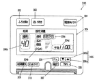
図3は遠隔操作装置300の一例を示す模式図である。
図3に示すように、遠隔操作装置300は、電源スイッチ301、ふろ自動スイッチ302、追い焚きスイッチ303、液晶表示部304、メニュースイッチ305、上下スイッチ306、確定スイッチ307、予約スイッチ308、給湯優先スイッチ309およびおまかせスイッチ310を含む。
【0059】
使用者により電源スイッチ301、ふろ自動スイッチ302、追い焚きスイッチ303、メニュースイッチ305、上下スイッチ306、確定スイッチ307、予約スイッチ308、給湯優先スイッチ309およびおまかせスイッチ310が押下操作される。それにより、遠隔操作装置300は、後述するヒートポンプ給湯装置100の制御部に所定の指令信号を送信する。制御部は、遠隔操作装置300より送信される所定の指令信号を受信し、ヒートポンプ給湯装置100の各構成要素を制御する。
【0060】
使用者が電源スイッチ301を押下すると、後述の制御部が第2の流量センサ14からの流量値を受信可能な待機状態に設定される。また、冷媒循環回路110の動作中に使用者が再度電源スイッチ301を押下すると、後述の終了前動作が行われた後、冷媒循環回路110の動作が停止される。ふろ自動スイッチ302を押下することにより図1の浴槽10内に図示しない水回路により所定の温度の水が蓄えられる。追い焚きスイッチ303を押下することにより冷媒循環回路110および第2の水回路130が動作し、浴槽10内の温水が追い焚きされる。
【0061】
また、液晶表示部304には、温水の設定温度304a、設定湯量304b、運転状態304cおよび現在時刻304dが表示される。
【0062】
例えば、使用者は、メニュースイッチ305を押下することにより、温水の温度の設定、湯量の設定、運転状態の設定および現在時刻の設定の切り替えを行い、上下スイッチ306a,306bを押下することにより各設定を行い、確定スイッチ307を押下することにより設定内容を確定する。給湯優先スイッチ309を押下することにより給湯を優先させるか浴槽10を優先させるかを切り替える。
【0063】
例えば、給湯条件を設定する場合、まず給湯優先スイッチ309を押下する。温水の温度を設定する場合には、メニュースイッチ305により設定温度304aを選択し、さらに上下スイッチ306bを押下することにより給湯時の設定温度が上昇し、上下スイッチ306aを押下することにより給湯時の設定温度が下降する。ここで、上下スイッチ306aを押下し続けることにより設定温度304aが例えば35℃以下に設定すると、設定温度304aの代わりに「給湯切」が表示される。この場合、冷媒循環回路110の動作が停止され、給湯栓16の蛇口から水道水Wが供給される。
【0064】
また、湯量を設定する場合、メニュースイッチ305により設定湯量304bを選択し、さらに上下スイッチ306bを押下することにより湯量が多めに設定され、上下スイッチ306aを押下することにより湯量が少なめに設定される。また、使用者は、予約スイッチ308を押下することにより、所定の時刻に所定の動作を行うよう設定することができる。
【0065】
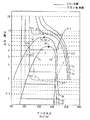
図4はヒートポンプにおけるCO2冷媒の状態変化をフロン系冷媒と比較して示すモリエル線図である。
【0066】
図4の縦軸は圧力を示し、横軸はエンタルピを示す。また、一点鎖線CはCO2冷媒の状態変化を示し、Fはフロン系冷媒の状態変化を示す。C1はCO2冷媒の飽和液線を示し、C2はCO2冷媒の飽和蒸気曲線を示し、F1はフロン系冷媒の飽和液線を示し、F2はフロン系冷媒の飽和蒸気曲線を示す。PcはCO2冷媒の臨界点を示し、Pfはフロン系冷媒の臨界点を示す。TcはCO2冷媒の等温線を示し、Tfはフロン系冷媒の等温線を示す。
【0067】
飽和液線C1,F1よりも低エンタルピ側では、冷媒は液体状態となり、飽和液線C1,F1よりも高エンタルピ側でかつ飽和蒸気線C2,F2より低エンタルピ側では、冷媒は液体と気体との二相状態となり、飽和蒸気線C2,F2よりも高エンタルピ側では、冷媒は気体状態となる。また、臨界点以上の圧力では、冷媒は超臨界状態となる。
【0068】
図4の位置S11,S21は、吸熱器の出口および圧縮機の入口に相当し、位置S12,S22は圧縮機の出口および放熱器の入口の相当し、位置S13,S23は放熱器の出口および減圧弁の入口に相当し、位置S14,S24は減圧弁の出口および吸熱器の入口に相当する。
【0069】
まず、CO2冷媒の状態変化について説明する。位置S11のCO2冷媒は、圧縮機によって高温高圧の超臨界のガス状態になり、位置S12に移行する。この過程でCO2冷媒の圧力およびエンタルピが増加する。次に、位置S12のCO2冷媒が放熱器を通過することにより熱が水に放出され、位置S13に移行する。配管の圧力損失を無視すると、この過程でCO2冷媒の圧力は変化せず、エンタルピが低下する。このとき、CO2冷媒の温度は低下する。さらに、位置S13のCO2冷媒が減圧弁を通過することにより低温低圧の液体およびガスの二相状態になり、位置S14に移行する。この過程でCO2冷媒の圧力は低下し、エンタルピは変化しない。その後、位置S14のCO2冷媒が吸熱器を通過することにより外気の熱を吸収しつつ低温低圧のガス状態になり、位置S11に移行する。この過程で圧力は変化せず、エンタルピが増加する。
【0070】
次に、フロン系冷媒の状態変化について説明する。位置S21のフロン系冷媒は圧縮機によって高温高圧のガス状態になり、位置S22に移行する。この過程でフロン系冷媒の圧力およびエンタルピが増加する。次に、位置S22のフロン系冷媒が放熱器を通過することにより熱が水に放出され、位置S23に移行する。この過程でフロン系冷媒の圧力は変化せず、エンタルピが低下する。このとき、フロン系冷媒の温度が低下する。それにより、フロン系冷媒は液化する。さらに、位置S23のフロン系冷媒が減圧弁を通過することにより低温低圧の液体およびガスの二相状態になり、位置S24に移行する。この過程でフロン系冷媒の圧力は低下し、エンタルピは変化しない。その後、位置S24のフロン系冷媒が吸熱器を通過することにより外気の熱を吸収しつつ低温低圧のガス状態になり、位置S21に移行する。この過程で圧力は変化せずエンタルピが増加する。
【0071】
このように、CO2冷媒では、フロン系冷媒と比較すると、サイクル内での作動圧力が4〜5倍と高くなる一方で、低圧から高圧への圧縮比が小さく、圧縮機での圧縮効率が向上する。その結果、ヒートポンプの効率を示す成績係数COP(熱出力/駆動エネルギー入力)が大きくなる。また、低温下でも低圧が高いため、フロン系冷媒では対応が困難であった寒冷地などでも容易に作動することができる。
【0072】
次に、放熱器におけるCO2冷媒およびフロン系冷媒の加熱特性について説明する。図5は放熱器におけるフロン系冷媒およびCO2冷媒の加熱特性を示す図である。また、図6は放熱器の構造を示す模式図である。
【0073】
図5において、縦軸が温度を示し、横軸が放熱器の冷媒入口および水出口から冷媒出口および水入口までの位置を示す。
【0074】
図6に示すように、第1の放熱器3には、曲折された冷媒用の蛇行配管500が形成されている。その蛇行配管500に沿って水用の蛇行配管501が形成されている。蛇行配管501は蛇行配管500と接触するように設けられている。それにより、熱量の変換が効率よく行われる。
【0075】
蛇行配管500の一端には冷媒入口Cinが設けられ、蛇行配管500の他端には冷媒出口Coutが設けられる。また、蛇行配管501の一端には水出口Woutが設けられ、蛇行配管501の他端には水入口Winが設けられる。すなわち、冷媒入口Cinと水出口Woutとが蛇行配管500,501の同じ一端に設けられ、冷媒出口Coutと水入口Winとが蛇行配管500,501の同じ他端に設けられる。
【0076】
それにより、図5(b)に示す一定の比例関係を有する温度変化が第1の放熱器3内でも維持され、冷媒から水への熱の供給が効率よく行われる。
【0077】
図5(a)はフロン系冷媒の温度変化A1および水の温度変化B1を示し、図5(b)はCO2冷媒の温度変化A2および水の温度変化B2を示す。
【0078】
図5(a)に示すように、冷媒入口Cinから流入したフロン系冷媒が水に熱量を供給することにより、フロン系冷媒の温度が直線的に低下する。しかし、その後、フロン系冷媒が凝縮域に入り、ガス状態から液体状態に変遷する。その際に、潜熱が必要となり、フロン系冷媒の熱量が潜熱として消費される。そのため、フロン系冷媒の温度が、矢印A11で示すように、変化せず、フロン系冷媒から水に効率良く熱が供給されない。したがって、水入口Winから流入した水の温度は、矢印B11で示すように緩やかに上昇することになる。
【0079】
一方、図5(b)に示すように、冷媒入口Cinから流入したCO2冷媒が水に熱量を供給することにより、CO2冷媒の温度が直線的に低下する。この場合、CO2冷媒は、超臨界域にあるため、潜熱が必要とならない。そのため、CO2冷媒が冷媒出口Coutから排出されるまで、CO2冷媒の温度は、矢印A21で示すように、直線的に低下し続ける。それにより、水入口Winから流入した水にCO2冷媒から効率的に熱量が供給され、水の温度は、矢印B21で示すように、直線的に上昇し続け、水出口Woutから排出される。
【0080】
上記の温度特性により、フロン系冷媒を用いた場合には、常温の水を出湯温度P1(=65℃)までしか上昇させることができないが、CO2冷媒を用いることにより、常温の水を出湯温度P2(=90℃)まで上昇させることができる。
【0081】
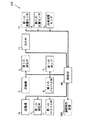
図7は図1のヒートポンプ給湯装置100の制御系の構成を示すブロック図である。
【0082】
図7に示すように、制御部40は、第1の流量センサ12により測定される流量値、第2の流量センサ14により測定される流量値、出湯温度センサ15により測定される温度値および遠隔操作装置300から与えられる指令信号を受け取る。
【0083】
制御部40は、第1の流量センサ12により測定される流量値、第2の流量センサ14により測定される流量値、出湯温度センサ15により測定される温度値および遠隔操作装置300から与えられる指令信号に基づいて、送風機1bの回転数、第1の減圧弁4の開度、第1のバイパス弁7の開閉、圧縮機2の回転数、第2のバイパス弁8の開閉、第2の減圧弁6の開度、第1のポンプ9の回転数および混合弁13の切り替えを制御する。
【0084】
次に、本実施例に係るヒートポンプ給湯装置100の停止時の動作について説明する。ここでは、第1の水回路120を用いる場合の動作を説明する。第2の水回路130を用いた場合の動作も同様である。
【0085】
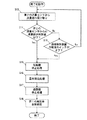
図8は本実施例に係るヒートポンプ給湯装置100における制御部40の終了前動作の第1の例を示すフローチャートである。
【0086】
図8に示すように、制御部40は、第2の流量センサ14から配管45を通過する温水の流量値を受け取る(ステップS1)。
【0087】
次に、制御部40は、第2の流量センサ14からの流量値が所定値以下であるか否かを判別する(ステップS2)。第2の流量センサ14からの流量値が所定値以下の場合、制御部40は、圧縮機2の停止処理を行う(ステップS3)。圧縮機2の停止処理については後述する。
【0088】
次に、制御部40は、送風機1bの停止の処理を行う(ステップS4)。さらに、制御部40は、第1の減圧弁4の全開処理を行う(ステップS5)。これにより、終了前動作が終了する。
【0089】
ステップS2において、第2の流量センサ14からの流量値が所定値を超えている場合、制御部40は、遠隔操作装置300の電源スイッチ301または、追い焚きスイッチ303がオフされたか否かを判別する(ステップS6)。
【0090】
遠隔操作装置300の電源スイッチ301がオフされた場合、制御部40は、圧縮機2の停止処理(ステップS3)、送風機1bの停止処理(ステップS4)および第1の減圧弁4の全開処理(ステップS5)を行う。なお、第1の減圧弁4の開度はステッピングモータにより制御される。
【0091】
遠隔操作装置300の電源スイッチ301がオフされていない場合、ステップS1に戻り上記の処理を繰り返す。
【0092】
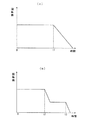
ここで、圧縮機2の停止処理について説明する。図9は制御部40による圧縮機2の停止処理における圧縮機2の回転数の変化を示す模式図であり、(a)は停止処理の第1の例を示し、(b)は停止処理の第2の例を示す。
【0093】
図9(a)および図9(b)において、縦軸は圧縮機2の単位時間当りの回転数を示し、横軸は時間を示す。
【0094】
図9(a)の例においては、制御部40は、時点t1で第2の流量センサ14からの流量値が所定値以下になるかまたは遠隔操作装置300の電源スイッチ301がオフされると、圧縮機2の単位時間当りの回転数を徐々に減少させ、所定時間経過後に圧縮機2を停止させる。例えば、圧縮機2の回転数を1秒間に0.5〜1Hzずつ低下させ、圧縮機2の回転数が最低回転数(例えば30Hz)になった時点で停止させる。
【0095】
また、図9(b)の例においては、制御部40は、時点t2で第2の流量センサ14からの流量値が所定値以下になるかまたは遠隔操作装置300の電源スイッチ301がオフされると、圧縮機2の回転数を低下させ、圧縮機2を一定回転数で所定時間回転させた後、時点t3で停止させる。例えば圧縮機2の回転数を50〜60Hzに低下させ、その回転数で所定時間回転させた後、停止させる。
【0096】
本例では、上記の圧縮機2の停止処理により、冷媒循環回路110内の潤滑油を圧縮機2に回収することができ、圧縮機2内の潤滑油が不足することを防止することができる。それにより、圧縮機2の安全性および信頼性を確保することができる。
【0097】
なお、配管45を流れる温水の流量が少ない場合、入水温度が高い場合等のように、給湯負荷が小さい場合には、圧縮機2の回転数が低い状態(例えば30Hz〜40Hz)になっているので、圧縮機2を即座に停止させてもよい。それにより、使用者が給湯栓16を閉じた後に第1の放熱器3により水が加熱されて使用者が再度給湯栓16を開いたときに蛇口から高温の湯が吐出することが防止される。
【0098】
また、上記の送風機1bの停止処理により、熱交換器1aによる大気からの吸熱量を低下させることができ、第1の放熱器3内部の過昇温を防止することができる。
【0099】
さらに、上記の第1の減圧弁4の全開処理により、即座に冷媒循環回路110内の圧力を均一にすることができる。それにより、ヒートポンプ給湯装置100の再起動時に圧力差による圧縮機2の負担を軽減することができる。
【0100】
なお、ステップS3の圧縮機2の停止処理、ステップS4の送風機1bの停止処理およびステップS5の第1の減圧弁4の全開処理のうちいずれか1つまたは2つを行ってもよい。なお、ステップS5の第1の減圧弁4の全開処理は、圧縮機2の停止後に行う必要がある。ただし、冬季に外気温度を検知して意図的に除霜運転を停止時に行う場合には、圧縮機2が動作している状態で第1の減圧弁4を開いてもよい。
【0101】
図10は本実施例に係るヒートポンプ給湯装置100における制御部40の終了前動作の第2の例を示すフローチャートである。
【0102】
図10に示すように、制御部40は、第2の流量センサ14から配管45を通過する温水の流量値を受け取る(ステップS7)。
【0103】
次に、制御部40は、第2の流量センサ14からの流量値が所定値以下であるか否かを判別する(ステップS8)。第2の流量センサ14からの流量値が所定値以下の場合、制御部40は、圧縮機2の停止処理を行う(ステップS9)。圧縮機2の停止処理は、第1の例と同様である。
【0104】
次に、制御部40は、送風機1bの停止の処理を行う(ステップS10)。さらに、制御部40は、第1の放熱器3のバイパス処理を行う(ステップS11)。この第1の放熱器3のバイパス処理においては、第2のバイパス弁8が開放され、第1のバイパス弁7および第1の減圧弁4が閉じられる。これにより、冷媒は第1の放熱器3を迂回する。その後、終了前動作が終了する。
【0105】
ステップS8において、第2の流量センサ14からの流量値が所定値を超えている場合、制御部40は、遠隔操作装置300の電源スイッチ301がオフされたか否かを判別する(ステップS12)。
【0106】
遠隔操作装置300の電源スイッチ301がオフされた場合、制御部40は、圧縮機2の停止処理(ステップS9)、送風機1bの停止処理(ステップS10)および第1の放熱器3のバイパス処理(ステップS11)を行う。
【0107】
遠隔操作装置300の電源スイッチ301がオフされていない場合、ステップS7に戻り上記の処理を繰り返す。
【0108】
本例では、上記の圧縮機2の停止処理により、冷媒循環回路110内の潤滑油を圧縮機2に回収することができ、圧縮機2内の潤滑油が不足することを防止することができる。それにより、圧縮機2の安全性および信頼性を確保することができる。
【0109】
また、上記の送風機1bの停止処理により、熱交換器1aによる大気からの吸熱量を低下させることができ、第1の放熱器3内部の過昇温を防止することができる。
【0110】
さらに、上記の第1の放熱器3のバイパス処理により、高温高圧ガス化した冷媒が配管36および第2のバイパス弁8を介して熱交換器1aに送られる。これにより、特に冬季において、霜が熱交換器1aに付着することを防止し、熱交換器1aに付着した霜を除去することができる。したがって、霜の付着による熱交換器1aの吸熱能力の低下を防止することができ、ヒートポンプ給湯装置100の再起動時における昇温速度を向上させることができる。
【0111】
なお、ステップS9の圧縮機2の停止処理、ステップS10の送風機1bの停止処理およびステップS11の第1の放熱器3のバイパス処理のうちいずれか1つまたは2つを行ってもよい。ただし、ステップS11の第1の放熱器3のバイパス処理は、圧縮機2の停止後に行う必要がある。
【0112】
また、第1の水回路120および冷媒循環回路110の運転および停止は、上記のように、第2の流量センサ14からの流量値に基づいて制御されるが、第2の水回路130および冷媒循環回路110の運転および停止は、遠隔操作装置300の追い焚きスイッチ303操作に基づいて制御される。
【0113】
なお、本実施例においては、使用者が給湯栓16を開いたか否かを判定するために、第2の流量センサ14により配管45内を流れる水量を検知することとしたが、これに限定されず、第1の流量センサ12により配管42内を流れる水量を検知することとしてもよい。または、使用者が給湯栓16を開いたか否かを判定するために、第1の流量センサ12および第2の流量センサ14の両方により配管42,45内を流れる水量を検知することとしてもよい。さらに、第1の流量センサを設けなくてもよい。また、流量センサの代わりに、流量スイッチ、圧力スイッチまたは温度センサなどにより配管42,45内の水の流量を検知してもほぼ同様の効果が得られる。
【0114】
(第2の実施例)
図11は本発明の第2の実施例に係る瞬間加熱式のヒートポンプ給湯装置101の構成を示す模式図である。
【0115】
図11に示すように、本実施例に係るヒートポンプ給湯装置101が第1の実施例に係る図1のヒートポンプ給湯装置100と異なる点は、配管46および第3のバイパス弁17を備える点である。
【0116】
この場合、配管46は、配管44から分岐するように設けられている。第3のバイパス弁17は配管46に介挿されている。
【0117】
図12は図11のヒートポンプ給湯装置101の制御系の構成を示すブロック図である。
【0118】
図12に示すように、本実施例に係るヒートポンプ給湯装置101の制御系の構成が第1の実施例に係るヒートポンプ給湯装置100の制御系の構成と異なる点は、制御部40が第3のバイパス弁17を制御する点である。
【0119】
この場合、制御部40は、第1の流量センサ12により測定される流量値、第2の流量センサ14により測定される流量値、出湯温度センサ15により測定される温度値および遠隔操作装置300から与えられる指令信号に基づいて、第3のバイパス弁17の開閉を制御する。
【0120】
次に、本実施例に係るヒートポンプ給湯装置101の停止時の動作について説明する。ここでは、第1の水回路120を用いる場合の動作を説明する。第2の水回路130を用いた場合の動作も同様である。
【0121】
図13は本実施例に係るヒートポンプ給湯装置101における制御部40の終了前動作の第1の例を示すフローチャートである。
【0122】
図13に示すように、制御部40は、第2の流量センサ14から配管45を通過する温水の流量値を受け取る(ステップS13)。
【0123】
次に、制御部40は、第2の流量センサ14からの流量値が所定値以下であるか否かを判別する(ステップS14)。第2の流量センサ14からの流量値が所定値以下の場合、制御部40は、圧縮機2の停止処理を行う(ステップS15)。圧縮機2の停止処理は、第1の実施例における圧縮機2の停止処理と同様である。
【0124】
次に、制御部40は、温水排出処理を行う(ステップS16)。この温水排出処理においては、第3のバイパス弁17が開放され、混合弁13の第1の入口および混合弁13の第2の入口が閉じられる。この場合、温水は配管44、第3のバイパス弁17および配管46を介して排出される。
【0125】
さらに、制御部40は、送風機1bの停止の処理を行う(ステップS17)。最後に、制御部40は、第1の減圧弁4の全開処理を行う(ステップS18)。これにより、終了前動作が終了する。
【0126】
ステップS14において、第2の流量センサ14からの流量値が所定値を超えている場合、制御部40は、遠隔操作装置300の電源スイッチ301がオフされたか否かを判別する(ステップS19)。
【0127】
遠隔操作装置300の電源スイッチ301がオフされた場合、制御部40は、圧縮機2の停止処理(ステップS15)、温水排出処理(ステップS16)、送風機1bの停止処理(ステップS17)および第1の減圧弁4の全開処理(ステップS18)を行う。
【0128】
遠隔操作装置300の電源スイッチ301がオフされていない場合、ステップS13に戻り上記の処理を繰り返す。
【0129】
本例では、上記の圧縮機2の停止処理により、冷媒循環回路110内の潤滑油を圧縮機2に回収することができ、圧縮機2内の潤滑油が不足することを防止することができる。それにより、圧縮機2の安全性および信頼性を確保することができる。
【0130】
また、上記の温水排出処理により、ヒートポンプ給湯装置100の停止時に第1の放熱器3によって加熱された温水が排出される。それにより、第1の放熱器3が冷却されるとともに、使用者が再度給湯栓16を開いた場合に、給湯後における第1の放熱器3内部の熱容量によって加熱された高温の湯が蛇口から吐出することを防止することができる。
【0131】
また、上記の送風機1bの停止処理により、熱交換器1aによる大気からの吸熱量を低下させることができ、第1の放熱器3内部の過昇温を防止することができる。
【0132】
さらに、上記の第1の減圧弁4の全開処理により、即座に冷媒循環回路110内の圧力を均一にすることができる。それにより、ヒートポンプ給湯装置100の再起動時に圧力差による圧縮機2の負担を軽減することができる。
【0133】
なお、ステップS15の圧縮機2の停止処理、ステップS16の温水排出処理、ステップS17の送風機1bの停止処理およびステップS18の第1の減圧弁4の全開処理のうちいずれか1つ、2つまたは3つを行ってもよい。なお、ステップS18の第1の減圧弁4の全開処理は、圧縮機2の停止後に行う必要がある。ただし、冬季に外気温度を検知して意図的に除霜運転を停止時に行う場合には、圧縮機2が動作している状態で第1の減圧弁4を開いてもよい。
【0134】
図14は本実施例に係るヒートポンプ給湯装置101における制御部40の終了前動作の第2の例を示すフローチャートである。
【0135】
図14に示すように、制御部40は、第2の流量センサ14から配管45を通過する温水の流量値を受け取る(ステップS20)。
【0136】
次に、制御部40は、第2の流量センサ14からの流量値が所定値以下であるか否かを判別する(ステップS21)。第2の流量センサ14からの流量値が所定値以下の場合、制御部40は、圧縮機2の停止処理を行う(ステップS22)。圧縮機2の停止処理は、第1の実施例における圧縮機2の停止処理と同様である。
【0137】
次に、制御部40は、温水排出処理を行う(ステップS23)。この温水排出処理においては、第3のバイパス弁17が開放され、混合弁13の第1の入口および混合弁13の第2の入口が閉じられる。この場合、温水は配管44、第3のバイパス弁17および配管46を介して排出される。
【0138】
さらに、制御部40は、送風機1bの停止の処理を行う(ステップS24)。最後に、制御部40は、第1の放熱器3のバイパス処理を行う(ステップS25)。この第1の放熱器3のバイパス処理においては、第2のバイパス弁8が開放され、第1のバイパス弁7および第1の減圧弁4が閉じられる。これにより、冷媒は第1の放熱器3を迂回する。その後、終了前動作が終了する。
【0139】
ステップS21において、第2の流量センサ14からの流量値が所定値を超えている場合、制御部40は、遠隔操作装置300の電源スイッチ301がオフされたか否かを判別する(ステップS26)。
【0140】
遠隔操作装置300の電源スイッチ301がオフされた場合、制御部40は、圧縮機2の停止処理(ステップS22)、温水排出処理(ステップS23)、送風機1bの停止処理(ステップS10)および第1の放熱器3のバイパス処理(ステップS11)を行う。
【0141】
遠隔操作装置300の電源スイッチ301がオフされていない場合、ステップS20に戻り上記の処理を繰り返す。
【0142】
本例では、上記の圧縮機2の停止処理により、冷媒循環回路110内の潤滑油を圧縮機2に回収することができ、圧縮機2内の潤滑油が不足することを防止することができる。それにより、圧縮機2の安全性および信頼性を確保することができる。
【0143】
また、上記の温水排出処理により、ヒートポンプ給湯装置100の停止時に第1の放熱器3によって加熱された温水が排出される。それにより、第1の放熱器3が冷却されるとともに、使用者が再度給湯栓16を開いた場合に、給湯後における第1の放熱器3内部の熱容量によって加熱された高温の湯が蛇口から吐出することを防止することができる。
【0144】
また、上記の送風機1bの停止処理により、熱交換器1aによる大気からの吸熱量を低下させることができ、第1の放熱器3内部の過昇温を防止することができる。
【0145】
さらに、上記の第1の放熱器3のバイパス処理により、高温高圧ガス化した冷媒が配管36および第2のバイパス弁8を介して熱交換器1aに送られる。これにより、特に冬季において、霜が熱交換器1aに付着することを防止し、熱交換器1aに付着した霜を除去することができる。したがって、霜の付着による熱交換器1aの吸熱能力の低下を防止することができ、ヒートポンプ給湯装置100の再起動時における昇温速度を向上させることができる。
【0146】
なお、ステップS22の圧縮機2の停止処理、ステップS23の温水排出処理、ステップS24の送風機1bの停止処理およびステップS25の第1の放熱器3のバイパス処理のうちいずれか1つ、2つまたは3つを行ってもよい。ただし、ステップS25の第1の放熱器3のバイパス処理は、圧縮機2の停止後に行う必要がある。
【0147】
また、第1の水回路120および冷媒循環回路110の運転および停止は、上記のように、第2の流量センサ14からの流量値に基づいて制御されるが、第2の水回路130および冷媒循環回路110の運転および停止は、遠隔操作装置300の追い焚きスイッチ303操作に基づいて制御される。
【0148】
(第3の実施例)
図15は本発明の第3の実施例に係る瞬間加熱式のヒートポンプ給湯装置102の構成を示す模式図である。
【0149】
図15に示すように、本実施例に係るヒートポンプ給湯装置102が第1の実施例に係る図1のヒートポンプ給湯装置100と異なる点は、第2のポンプ18、逆止弁19、タンク20、第4のバイパス弁21、第5のバイパス弁22および配管47〜51を備える点である。
【0150】
この場合、配管41は配管47および配管48に分岐している。配管47はタンク20の水入口に接続されている。配管48は配管45に接続され、配管48には第5のバイパス弁22が介挿されている。また、配管50の一端はタンク20の水出口に接続されており、配管50の他端は第1の放熱器3の水入口に接続されている。配管50には第2のポンプ18および第1の流量センサ12が介挿され、第2のポンプ18に並列に逆止弁19が接続されている。また、配管51は配管44から分岐し、タンク20の湯入口に接続されている。配管51には第4のバイパス弁21が介挿されている。タンク20の湯出口は、配管49を介して混合弁13の第2の入口に接続されている。
【0151】
通常の給湯時には、配管41に流入した水道水Wが配管47を通してタンク20の水入口に供給され、タンク20の水出口から排出される水が配管50および逆止弁19を通して第1の放熱器3に供給される。第1の放熱器3により加熱された温水が配管44、混合弁13および配管45を通して給湯栓16から排出される。
【0152】
本実施例においては、出湯温度センサ15によって測定される配管45を通過する温水の温度が過度に高い場合、第5のバイパス弁22が開放され、配管48を介して水道水Wが温水に足される。これにより、適温の温水が給湯栓16の蛇口から排出される。
【0153】
図16は図15のヒートポンプ給湯装置102の制御系の構成を示すブロック図である。
【0154】
図16に示すように、本実施例に係るヒートポンプ給湯装置102の制御系の構成が第1の実施例に係るヒートポンプ給湯装置100の制御系の構成と異なる点は、制御部40が第2のポンプ18、第4のバイパス弁21および第5のバイパス弁22を制御する点である。
【0155】
この場合、制御部40は、第1の流量センサ12により測定される流量値、第2の流量センサ14により測定される流量値、出湯温度センサ15により測定される温度値および遠隔操作装置300から与えられる指令信号に基づいて、第2のポンプ18の回転数、第4のバイパス弁21の開閉および第5のバイパス弁22の開閉を制御する。
【0156】
次に、本実施例に係るヒートポンプ給湯装置102の停止時の動作について説明する。ここでは、第1の水回路120を用いる場合の動作を説明する。第2の水回路130を用いた場合の動作も同様である。
【0157】
図17は本実施例に係るヒートポンプ給湯装置102における制御部40の終了前動作の第1の例を示すフローチャートである。この場合、混合弁13の第1の入口が開かれ、第2の入口が閉じられ、第4のバイパス弁21が閉じられ、第5のバイパス弁22が閉じられている。
【0158】
図17に示すように、制御部40は、第2の流量センサ14から配管45を通過する温水の流量値を受け取る(ステップS27)。
【0159】
次に、制御部40は、第2の流量センサ14からの流量値が所定値以下であるか否かを判別する(ステップS28)。第2の流量センサ14からの流量値が所定値以下の場合、制御部40は、蓄熱処理を行う(ステップS29)。
【0160】
この蓄熱処理においては、混合弁13の第1の入口が閉じられ、第4のバイパス弁21が開放され、第2のポンプ18が動作する。それにより、第1の放熱器3により加熱された温水が第4のバイパス弁21、配管51、タンク20、配管50および第2のポンプ18を経由して第1の放熱器3に戻る。このようにして、温水が第1の放熱器3およびタンク20を循環することにより温水の熱がタンク20内部に蓄えられる。
【0161】
次に、制御部40は、圧縮機2の停止処理を行う(ステップS30)。圧縮機2の停止処理は、第1の実施例における圧縮機2の停止処理と同様である。
【0162】
さらに、制御部40は、送風機1bの停止の処理を行う(ステップS31)。最後に、制御部40は、第1の減圧弁4の全開処理を行う(ステップS32)。これにより、終了前動作が終了する。
【0163】
ステップS28において、第2の流量センサ14からの流量値が所定値を超えている場合、制御部40は、遠隔操作装置300の電源スイッチ301がオフされたか否かを判別する(ステップS33)。
【0164】
遠隔操作装置300の電源スイッチ301がオフされた場合、制御部40は、蓄熱処理(ステップS29)、圧縮機2の停止処理(ステップS30)、送風機1bの停止処理(ステップS31)および第1の減圧弁4の全開処理(ステップS32)を行う。
【0165】
遠隔操作装置300の電源スイッチ301がオフされていない場合、ステップS27に戻り上記の処理を繰り返す。
【0166】
本例では、上記の蓄熱処理により、第1の放熱器3により加熱された温水の熱量がタンク20に蓄えられるので、使用者が再度給湯栓16を開いたときに蛇口から熱湯が吐出することが防止される。さらに、タンク20に貯留された温水を使用することができる。この場合、制御部40の制御により混合弁13の第2の入口を開放することにより、タンク20内に貯留された温水を配管49および配管45を介して給湯栓16の蛇口から排出する。それにより、無駄なエネルギーの消費が低減される。
【0167】
また、上記の圧縮機2の停止処理により、冷媒循環回路110内の潤滑油を圧縮機2に回収することができ、圧縮機2内の潤滑油が不足することを防止することができる。それにより、圧縮機2の安全性および信頼性を確保することができる。
【0168】
また、上記の送風機1bの停止処理により、熱交換器1aによる大気からの吸熱量を低下させることができ、第1の放熱器3内部の過昇温を防止することができる。
【0169】
さらに、上記の第1の減圧弁4の全開処理により、即座に冷媒循環回路110内の圧力を均一にすることができる。それにより、ヒートポンプ給湯装置100の再起動時に圧力差による圧縮機2の負担を軽減することができる。
【0170】
なお、ステップS29の蓄熱処理、ステップS30の圧縮機2の停止処理、ステップS31の送風機1bの停止処理およびステップS32の第1の減圧弁4の全開処理のうちいずれか1つ、2つまたは3つを行ってもよい。なお、ステップS29の蓄熱処理は最初に行う必要があり、ステップS32の第1の減圧弁4の全開処理は、圧縮機2の停止後に行う必要がある。ただし、冬季に外気温度を検知して意図的に除霜運転を停止時に行う場合には、圧縮機2が動作している状態で第1の減圧弁4を開いてもよい。
【0171】
図18は本実施例に係るヒートポンプ給湯装置102における制御部40の終了前動作の第2の例を示すフローチャートである。この場合、混合弁13の第1の入口が開かれ、第2の入口が閉じられ、第4のバイパス弁21が閉じられ、第5のバイパス弁22が閉じられている。
【0172】
図18に示すように、制御部40は、第2の流量センサ14から配管45を通過する温水の流量値を受け取る(ステップS34)。
【0173】
次に、制御部40は、第2の流量センサ14からの流量値が所定値以下であるか否かを判別する(ステップS35)。第2の流量センサ14からの流量値が所定値以下の場合、制御部40は、蓄熱処理を行う(ステップS36)。
【0174】
この蓄熱処理においては、混合弁13の第1の入口が閉じられ、第4のバイパス弁21が開放され、第2のポンプ18が動作する。それにより、第1の放熱器3により加熱された温水が第4のバイパス弁21、配管51、タンク20、配管50および第2のポンプ18を経由して第1の放熱器3に戻る。このようにして、温水が第1の放熱器3およびタンク20を循環することにより温水の熱がタンク20内部に蓄えられる。
【0175】
次に、制御部40は、圧縮機2の停止処理を行う(ステップS37)。圧縮機2の停止処理は、第1の実施例における圧縮機2の停止処理と同様である。
【0176】
さらに、制御部40は、送風機1bの停止の処理を行う(ステップS38)。最後に、制御部40は、第1の放熱器3のバイパス処理を行う(ステップS39)。これにより、終了前動作が終了する。
【0177】
上記の第1の放熱器3のバイパス処理においては、第2のバイパス弁8が開放され、第1のバイパス弁7および第1の減圧弁4が閉じられる。これにより、冷媒は第1の放熱器3を迂回する。
【0178】
ステップS35において、第2の流量センサ14からの流量値が所定値を超えている場合、制御部40は、遠隔操作装置300の電源スイッチ301がオフされたか否かを判別する(ステップS40)。
【0179】
遠隔操作装置300の電源スイッチ301がオフされた場合、制御部40は、蓄熱処理(ステップS36)、圧縮機2の停止処理(ステップS37)、送風機1bの停止処理(ステップS38)および第1の放熱器3のバイパス処理(ステップS39)を行う。
【0180】
遠隔操作装置300の電源スイッチ301がオフされていない場合、ステップS34に戻り上記の処理を繰り返す。
【0181】
本例では、上記の蓄熱処理により、第1の放熱器3により加熱された温水の熱量がタンク20に蓄えられるので、使用者が再度給湯栓16を開いたときに蛇口から熱湯が吐出することが防止される。さらに、タンク20に貯留された温水を使用することができる。この場合、制御部40の制御により混合弁13の第2の入口を開放することにより、タンク20内に貯留された温水を配管49および配管45を介して給湯栓16の蛇口から排出する。それにより、無駄なエネルギーの消費が低減される。
【0182】
また、上記の圧縮機2の停止処理により、冷媒循環回路110内の潤滑油を圧縮機2に回収することができ、圧縮機2内の潤滑油が不足することを防止することができる。それにより、圧縮機2の安全性および信頼性を確保することができる。
【0183】
また、上記の送風機1bの停止処理により、熱交換器1aによる大気からの吸熱量を低下させることができ、第1の放熱器3内部の過昇温を防止することができる。
【0184】
さらに、上記の第1の放熱器3のバイパス処理により、高温高圧ガス化した冷媒が配管36および第2のバイパス弁8を介して熱交換器1aに送られる。これにより、特に冬季において、霜が熱交換器1aに付着することを防止し、熱交換器1aに付着した霜を除去することができる。したがって、霜の付着による熱交換器1aの吸熱能力の低下を防止することができ、ヒートポンプ給湯装置100の再起動時における昇温速度を向上させることができる。
【0185】
なお、ステップS36の蓄熱処理、ステップS37の圧縮機2の停止処理、ステップS38の送風機1bの停止処理およびステップS39の第1の放熱器3のバイパス処理のうちいずれか1つ、2つまたは3つを行ってもよい。ただし、ステップS36の蓄熱処理は最初に行う必要があり、ステップS39の第1の放熱器3のバイパス処理は、圧縮機2の停止後に行う必要がある。
【0186】
なお、夜間等の不使用時に制御部40の制御により冷媒循環回路110および第1の水回路120を動作させることによりタンク20に温水を貯留してもよい。この場合、使用時に制御部40の制御により混合弁13の第2の入口を開放することにより、タンク20内に貯留された温水を配管49および配管45を介して給湯栓16の蛇口から排出する。
【0187】
また、混合弁13の第1および第2の入口を開放することにより、第1の放熱器3により加熱された温水およびタンク20に貯留された温水の両方を配管49および配管45を介して給湯栓16の蛇口から排出することができる。また、第1の水回路120および冷媒循環回路110の運転および停止は、上記のように、第2の流量センサ14からの流量値に基づいて制御されるが、第2の水回路130および冷媒循環回路110の運転および停止は、遠隔操作装置300の追い焚きスイッチ303操作に基づいて制御される。
【0188】
本実施例においては、第1の減圧弁4および第2の減圧弁6が減圧手段に相当し、第2のバイパス弁8が冷媒流路切り替え手段に相当し、第1の流量センサ12および第2の流量センサ14が判定手段および流量検知手段に相当し、混合弁13が流路切り替え手段に相当し、第3のバイパス弁17が水路切り替え手段に相当し、タンク20が貯留手段に相当し、制御部40が制御手段、判定手段および要否判定手段に相当し、電源スイッチ301が操作スイッチおよび判定手段に相当し、追い焚きスイッチ303が動作スイッチおよび判定手段に相当する。
【0189】
【発明の効果】
本発明に係るヒートポンプ給湯装置によれば、判定手段によって加熱が必要であると判定された場合に、制御手段によって冷媒循環回路の動作が開始される。それにより、水供給路により放熱器の水流路に導かれた水が放熱器によって加熱される。放熱器により加熱された水は水供給路により所定場所に導かれる。これにより、使用者に加熱された水を供給することができる。また、判定手段により加熱が不要であると判定された場合に、冷媒循環回路の動作を停止させる前に、制御手段によって所定の終了前動作が実行される。このように、冷媒循環回路が急停止されずに終了前動作が実行された後に停止されるので、冷媒循環回路の急停止によるヒートポンプ給湯装置の過昇温状態や動作不良の発生を防止することができる。
【図面の簡単な説明】
【図1】本発明の第1の実施例に係る瞬間加熱式のヒートポンプ給湯装置の構成を示す模式図
【図2】本実施例に係るヒートポンプ給湯装置の斜視図
【図3】遠隔操作装置の一例を示す模式図
【図4】ヒートポンプにおけるCO2冷媒の状態変化をフロン系冷媒と比較して示すモリエル線図
【図5】放熱器におけるフロン系冷媒およびCO2冷媒の加熱特性を示す図
【図6】放熱器の構造を示す模式図
【図7】図1のヒートポンプ給湯装置の制御部の構成を示すブロック図
【図8】本発明の第1の実施例に係るヒートポンプ給湯装置における制御部の終了前動作の第1の例を示すフローチャート
【図9】制御部による停止処理における圧縮機の回転数の変化を示す模式図
【図10】本発明の第1の実施例に係るヒートポンプ給湯装置における制御部の終了前動作の第2の例を示すフローチャート
【図11】本発明の第2の実施例に係る瞬間加熱式のヒートポンプ給湯装置の構成を示す模式図
【図12】図11のヒートポンプ給湯装置の制御部の構成を示すブロック図
【図13】本発明の第2の実施例に係るヒートポンプ給湯装置における制御部の終了前動作の第1の例を示すフローチャート
【図14】本発明の第2の実施例に係るヒートポンプ給湯装置における制御部の終了前動作の第2の例を示すフローチャート
【図15】本発明の第3の実施例に係る瞬間加熱式のヒートポンプ給湯装置の構成を示す模式図
【図16】図15のヒートポンプ給湯装置の制御部の構成を示すブロック図
【図17】本発明の第3の実施例に係るヒートポンプ給湯装置における制御部の終了前動作の第1の例を示すフローチャート
【図18】本発明の第3の実施例に係るヒートポンプ給湯装置における制御部の終了前動作の第2の例を示すフローチャート
【符号の説明】
1 吸熱器
1a 熱交換器
1b 送風機
2 圧縮機
3 第1の放熱器
4 第1の減圧弁
5 第2の放熱器
6 第2の減圧弁
8 第2のバイパス弁
12 第1の流量センサ
13 混合弁
14 第2の流量センサ
17 第3のバイパス弁
20 タンク
50 制御部
100,101,102 ヒートポンプ給湯装置
110 冷媒循環回路
120 第1の水回路
130 第2の水回路
300 遠隔操作装置
301 電源スイッチ
303 追い焚きスイッチ
W 水道水[0001]
TECHNICAL FIELD OF THE INVENTION
The present invention relates to a hot water supply device using a heat pump (hereinafter, referred to as a heat pump hot water supply device).
[0002]
[Prior art]
Conventionally, various heat pump water heaters have been developed. The heat pump mainly includes a heat absorber, a compressor, a radiator, and a pressure reducing valve, and the refrigerant circulates through a closed circuit including the heat absorber, the compressor, the radiator, and the pressure reducing valve. In this case, the refrigerant is made low-temperature and low-pressure by passing through the pressure reducing valve, and the low-temperature low-pressure refrigerant is supplied to the heat absorber to absorb the heat of the outside air. Furthermore, the refrigerant that has absorbed the heat is compressed by the compressor to have a high temperature and a high pressure, and the heat of the refrigerant is given to the tap water by the radiator. Thereby, tap water is heated with low electric power.
[0003]
Such a heat pump hot water supply device has a hot water storage tank, and a hot water storage type heat pump hot water supply device that stores pre-heated water in the hot water storage tank, and an instantaneous heating type heat pump hot water supply that instantly heats tap water when used. There is a device.
[0004]
In a hot water supply type heat pump hot water supply device, water stored in a hot water storage tank is circulated and heated by a pump at midnight under the control of a microcomputer. Accordingly, when the user opens the hot water tap, the water heated and stored in the hot water storage tank is supplied from the faucet. When the user closes the faucet, the supply of water from the hot water storage tank is stopped. In such a hot water supply type heat pump water heater, the operation and stop of the heat pump are controlled by the microcomputer regardless of the user's operation of opening and closing the tap.
[0005]
In the above-mentioned hot water supply type heat pump water supply apparatus, the hot water storage tank generally needs a capacity of about 300 to 400 liters to cover the amount of hot water used at home in a day, and thus it is difficult to reduce the size. Further, it is difficult to reduce the weight of the hot water storage tank in order to satisfy the pressure resistance performance. For this reason, the heat pump water heater is generally composed of two units in consideration of problems during transportation and installation work. Furthermore, after installation, the hot water storage tank is usually full and weighs several hundred kilograms. As a result, a large installation space for installing the heat pump hot water supply device is required, and a great load resistance is required for the installation location.
[0006]
Therefore, in recent years, development of an instant heating type heat pump hot water supply device having no hot water storage tank has been advanced (for example, see Patent Document 1).
[0007]
In this instant heating type heat pump hot water supply device, the tap water is instantaneously heated by operating the heat pump at the time of use, and the heated water is supplied from the faucet. Such an instant heating type heat pump hot water supply device does not require a hot water storage tank, and thus can be reduced in size and weight. In addition, there is no heat loss when storing hot water, and since heating is supplied only for the amount used, there is no waste and the electricity bill can be reduced. Furthermore, since hot water can be heated and supplied as needed, the hot water does not run out even if a large amount of hot water is used.
[0008]
[Patent Document 1]
JP-A-10-311597
[0009]
[Problems to be solved by the invention]
As described above, in the conventional instant heating type heat pump water heater, when the user closes the tap, the operation of the heat pump stops. That is, the operation and stop of the heat pump are performed at an arbitrary timing in conjunction with the operation of the user. Such an abrupt stop of the heat pump at an arbitrary timing may cause an overheated state or malfunction.
[0010]
Therefore, an object of the present invention is to provide an instantaneous heating type heat pump water heater with high reliability and safety, in which the occurrence of an overheated state and operation failure is prevented.
[0011]
[Means for Solving the Problems]
In order to solve the conventional problems, a heat pump water heater according to the present invention includes a water supply path that guides water to a predetermined location through a water flow path of a radiator, a determination unit that determines whether heating is necessary, and a determination unit. When it is determined that heating is necessary, the operation of the refrigerant circuit is started, and when the determination unit determines that heating is not required, the operation of the refrigerant circuit is stopped before the operation of the refrigerant circuit is stopped. Control means for executing a pre-operation.
[0012]
In the heat pump water heater according to the present invention, the operation of the refrigerant circuit is started by the control means when the determination means determines that heating is necessary. Thereby, the water guided to the water flow path of the radiator by the water supply path is heated by the radiator. The water heated by the radiator is guided to a predetermined place by a water supply path. In addition, when the determination unit determines that the heating is unnecessary, the control unit executes a predetermined pre-operation before stopping the operation of the refrigerant circuit.
[0013]
BEST MODE FOR CARRYING OUT THE INVENTION
The invention according to
[0014]
In the heat pump water heater according to the present invention, the operation of the refrigerant circuit is started by the control means when the determination means determines that heating is necessary. Thereby, the water guided to the water flow path of the radiator by the water supply path is heated by the radiator. The water heated by the radiator is guided to a predetermined place by a water supply path. Thereby, the heated water can be supplied to the user as needed. Further, when the determination unit determines that the heating is unnecessary while the refrigerant circuit is operating, the control unit executes a predetermined pre-operation before terminating the operation of the refrigerant circuit. As described above, since the refrigerant circulation circuit is stopped after the pre-end operation is performed without being suddenly stopped, it is possible to prevent an overheated state or malfunction of the heat pump water heater due to the sudden stop of the refrigerant circulation circuit. Can be.
[0015]
According to a second aspect of the present invention, in the configuration of the heat pump hot water supply apparatus according to the first aspect, the determining unit detects a flow rate of the water in the water supply path and a flow rate detected by the flow rate detecting unit. And a necessity judging means for judging necessity of heating based on the necessity.
[0016]
In this case, the flow rate of the water flowing through the water supply path is detected by the flow rate detecting means, and the necessity / unnecessity determining means determines the necessity of heating based on the detected flow rate. Accordingly, even when the user operates the tap to stop tapping water, or when the supply of water from the pipe is stopped due to, for example, water cutoff, the operation of the refrigerant circuit is stopped before the predetermined termination. The operation is performed. As a result, it is possible to prevent the heat pump hot water supply device from being overheated or malfunctioning.
[0017]
According to a third aspect of the present invention, in the configuration of the heat pump hot water supply apparatus according to the second aspect, an operation switch that allows a user to input whether or not water supply is required is further provided, and the control unit is configured to operate the refrigerant circulation circuit during operation. When the operation switch is turned off, a predetermined pre-operation is performed before the operation of the refrigerant circuit is stopped.
[0018]
In this case, the control switch starts the operation of the refrigerant circuit when the input of the hot water supply is input by the operation switch and the necessity determination unit determines that the heating is necessary based on the signal of the flow rate detection unit. If hot water is not required by the operation switch during the operation of the refrigerant circuit, a predetermined pre-operation is performed by the control unit before the operation of the refrigerant circuit is stopped. Thereby, it is possible to prevent the heat pump hot water supply device from being overheated or malfunctioning.
[0019]
According to a fourth aspect of the present invention, in the configuration of the heat pump water heater according to any one of the first to third aspects, the determining means includes an operation switch for instructing termination of the operation of the refrigerant circuit, And a necessity judging means for judging necessity of heating based on the operation.
[0020]
In this case, the end of the operation of the refrigerant circuit is commanded by the operation switch, and the necessity determining unit determines whether the heating is necessary based on the command of the operation switch. Thereby, when the user instructs the end of the operation by the operation switch, a predetermined pre-end operation is executed before stopping the operation of the refrigerant circuit. As a result, it is possible to prevent the heat pump hot water supply device from being overheated or malfunctioning.
[0021]
According to a fifth aspect of the present invention, in the configuration of the heat pump water heater according to any one of the first to fourth aspects, the operation before completion includes an operation of reducing the rotation speed of the compressor. In this case, the lubricating oil in the refrigerant circulation circuit can be collected by the compressor, and the shortage of lubricating oil in the compressor can be prevented. Thereby, safety and reliability of the compressor can be ensured.
[0022]
According to a sixth aspect of the present invention, in the configuration of the heat pump water heater according to any one of the first to fifth aspects, the operation before the end is an operation of stopping the compressor by continuously reducing the rotation speed of the compressor. Is included. In this case, the lubricating oil in the refrigerant circuit can be recovered by the compressor by continuously reducing the number of revolutions of the compressor, and shortage of lubricating oil in the compressor can be prevented.
[0023]
According to a seventh aspect of the present invention, in the configuration of the heat pump water heater according to any one of the first to fifth aspects, the operation before the termination is an operation of stopping the compressor by gradually reducing the rotation speed of the compressor. Is included. In this case, lubricating oil in the refrigerant circuit can be recovered by the compressor by gradually reducing the number of revolutions of the compressor, and shortage of lubricating oil in the compressor can be prevented.
[0024]
According to an eighth aspect of the present invention, in the configuration of the heat pump hot water supply device according to any one of the first to seventh aspects, a drainage channel for discharging water heated by the radiator, and water heated by the radiator. And a water channel switching means for selectively guiding the water to a water supply channel or a drain channel, and the pre-operation includes switching the channel switching device so that water heated by the radiator is discharged from the drain channel. Including.
[0025]
In this case, the channel of the water heated by the radiator is switched to the drainage channel by the channel switching means, and the water heated by the radiator is discharged from the drainage channel to the outside of the heat pump water heater. Thereby, while the radiator is cooled, high-temperature water heated by the heat capacity inside the radiator after hot water supply can be prevented from being discharged from the faucet when the user opens the hot water tap again. .
[0026]
According to a ninth aspect of the present invention, in the configuration of the heat pump hot water supply apparatus according to any one of the first to eighth aspects, the heat absorber is a heat exchanger that gives the heat of the atmosphere to the refrigerant and a blower that sends the atmosphere to the heat exchanger. And the pre-end operation includes an operation of stopping the blower. In this case, the amount of heat absorbed from the atmosphere by the heat exchanger can be reduced. Thereby, it is possible to prevent an excessive temperature rise inside the radiator.
[0027]
According to a tenth aspect of the present invention, in the configuration of the heat pump water heater according to any one of the first to ninth aspects, the operation before completion includes an operation of releasing a pressure reducing function of the pressure reducing means. In this case, the pressure in the refrigerant circuit can be immediately made uniform. This can reduce the load on the compressor due to the pressure difference when the heat pump water heater is restarted.
[0028]
According to an eleventh aspect of the present invention, in the heat pump water heater according to any one of the first to ninth aspects, the refrigerant circulation circuit includes a refrigerant bypass flow path bypassing the radiator and a refrigerant flow path of the radiator. And a refrigerant flow switching means for selectively guiding the refrigerant to the refrigerant bypass flow path, and the pre-operation includes switching the refrigerant flow switching means so that the refrigerant is guided to the refrigerant bypass flow path.
[0029]
In this case, the refrigerant flow path switching means switches the refrigerant flow path to a refrigerant bypass flow path for bypassing the radiator. As a result, the high-temperature and high-pressure gasified refrigerant is sent to the heat exchanger without passing through the radiator. This can prevent frost from adhering to the heat exchanger and remove frost adhering to the heat exchanger, particularly in winter. Therefore, it is possible to prevent a decrease in the heat absorbing ability of the heat exchanger due to the adhesion of frost, and to improve a temperature rising rate when the heat pump water heater is restarted.
[0030]
According to a twelfth aspect of the present invention, in the configuration of the heat pump water heater according to any one of the first to eleventh aspects, the heat pump hot water supply apparatus further includes a heat storage unit that accumulates a heat amount. This includes an operation of guiding the amount of heat to the heat storage means.
[0031]
In this case, the amount of heat of the water heated by the radiator is stored in the heat storage means. Thus, it is possible to prevent high-temperature water from being discharged when it is determined that water is necessary again. In addition, since the amount of heat that is originally radiated is stored in the heat storage means, waste of heat energy can be reduced.
[0032]
According to a thirteenth aspect of the present invention, in the configuration of the heat pump water heater according to the twelfth aspect, the heat storage means includes a storage means for storing the water heated by the radiator. The apparatus further includes a flow path switching unit that guides one or both of the stored water to the water supply path.
[0033]
In this case, the water heated by the radiator can be stored in the storage means. Further, one or both of the water from the radiator and the water stored in the storage means can be used by being guided to the water supply path by the flow path switching means. Thereby, consumption of useless energy is reduced. In addition, by giving priority to the stored water, heated water is supplied to the water supply path from the beginning of hot water supply, and the usability is improved.
[0034]
According to a fourteenth aspect of the present invention, in the heat pump water heater according to any one of the first to thirteenth aspects, the refrigerant is made of carbon dioxide. By using carbon dioxide as the refrigerant, the working pressure in the compressor can be increased, and the compression ratio from low pressure to high pressure can be reduced. Thereby, the compression efficiency in the compressor is improved, and high-temperature water can be supplied. Furthermore, since the refrigerant is in a supercritical state in the radiator, latent heat is not required. Thus, heat can be efficiently supplied from the refrigerant to the water. As a result, the coefficient of performance COP (heat output / drive energy input) indicating the efficiency of the heat pump increases. Further, since the low pressure is high even at a low temperature, the heat pump hot water supply device can be easily operated even in a cold region.
[0035]
【Example】
Hereinafter, embodiments of the present invention will be described with reference to the drawings.
[0036]
(First embodiment)
FIG. 1 is a schematic diagram showing the configuration of an instant heating type heat pump hot
[0037]
As shown in FIG. 1, the heat
[0038]
The
[0039]
The refrigerant outlet of the heat exchanger 1a is connected to the inlet of the
[0040]
The
[0041]
The
[0042]
In heat pump hot
[0043]
In the heat pump hot
[0044]
In the heat pump hot
[0045]
Next, each operation of the
[0046]
First, a method of heating tap water W using
[0047]
In the
[0048]
On the other hand, in the
[0049]
The tap water W that has flowed into the
[0050]
Here, when the temperature of the hot water passing through the
[0051]
Next, a method of reheating water or low-temperature hot water in the
[0052]
In the
[0053]
On the other hand, in the
[0054]
The tap water W is heated using the
[0055]
In this case, the first
[0056]
FIG. 2 is a perspective view of the heat
As shown in FIG. 2, the
[0057]
The height L1 of the
[0058]
FIG. 3 is a schematic diagram showing an example of the
As shown in FIG. 3, the
[0059]
The user presses the
[0060]
When the user presses the
[0061]
The
[0062]
For example, the user switches the setting of the temperature of hot water, the setting of the amount of hot water, the setting of the operation state, and the setting of the current time by pressing the
[0063]
For example, when setting hot water supply conditions, first, the hot water
[0064]
When setting the amount of hot water, the set amount of hot water is set by selecting the set amount of
[0065]
FIG. 4 shows
[0066]
The vertical axis in FIG. 4 indicates pressure, and the horizontal axis indicates enthalpy. The dashed-dotted line C represents CO 2 The state change of the refrigerant is indicated, and F indicates the state change of the CFC-based refrigerant. C1 is CO 2 Shows the saturated liquid line of the refrigerant, where C2 is CO 2 A saturated vapor curve of the refrigerant is shown, F1 represents a saturated liquid curve of the CFC-based refrigerant, and F2 represents a saturated vapor curve of the CFC-based refrigerant. Pc is CO 2 Indicates the critical point of the refrigerant, and Pf indicates the critical point of the CFC-based refrigerant. Tc is CO 2 It shows the isotherm of the refrigerant, and Tf shows the isotherm of the CFC-based refrigerant.
[0067]
On the lower enthalpy side than the saturated liquid lines C1 and F1, the refrigerant is in a liquid state, and on the higher enthalpy side than the saturated liquid lines C1 and F1 and on the lower enthalpy side than the saturated vapor lines C2 and F2, the refrigerant is liquid and gas The refrigerant is in a gaseous state on the enthalpy side higher than the saturated vapor lines C2 and F2. At a pressure higher than the critical point, the refrigerant enters a supercritical state.
[0068]
The positions S11 and S21 in FIG. 4 correspond to the outlet of the heat absorber and the inlet of the compressor, the positions S12 and S22 correspond to the outlet of the compressor and the inlet of the radiator, and the positions S13 and S23 correspond to the outlet of the radiator. The positions correspond to the inlet of the pressure reducing valve, and the positions S14 and S24 correspond to the outlet of the pressure reducing valve and the inlet of the heat absorber.
[0069]
First, CO 2 The state change of the refrigerant will be described. CO at position S11 2 The refrigerant is brought into a high-temperature / high-pressure supercritical gas state by the compressor, and moves to the position S12. In this process, CO 2 The pressure and enthalpy of the refrigerant increase. Next, CO at the position S12 2 When the refrigerant passes through the radiator, heat is released to the water, and the process moves to position S13. Neglecting the pressure loss in the piping, CO 2 The pressure of the refrigerant does not change, and the enthalpy decreases. At this time, CO 2 The temperature of the refrigerant drops. Further, the CO of the position S13 2 When the refrigerant passes through the pressure reducing valve, the refrigerant enters a two-phase state of a low-temperature and low-pressure liquid and gas, and moves to a position S14. In this process, CO 2 The refrigerant pressure drops and the enthalpy does not change. Then, the CO at the position S14 2 When the refrigerant passes through the heat absorber, the refrigerant enters a low-temperature low-pressure gas state while absorbing the heat of the outside air, and moves to the position S11. During this process the pressure does not change and the enthalpy increases.
[0070]
Next, a change in the state of the CFC-based refrigerant will be described. The fluorocarbon refrigerant at the position S21 is brought into a high-temperature and high-pressure gas state by the compressor, and shifts to the position S22. In this process, the pressure and enthalpy of the CFC-based refrigerant increase. Next, heat passes through the radiator at the position S22, where the heat is released to water, and the process proceeds to the position S23. In this process, the pressure of the CFC-based refrigerant does not change, and the enthalpy decreases. At this time, the temperature of the CFC-based refrigerant decreases. Thereby, the CFC-based refrigerant is liquefied. Further, when the CFC-based refrigerant at the position S23 passes through the pressure reducing valve, a two-phase state of low-temperature and low-pressure liquid and gas is obtained, and the process proceeds to the position S24. In this process, the pressure of the CFC-based refrigerant decreases, and the enthalpy does not change. After that, the fluorocarbon refrigerant at the position S24 passes through the heat absorber, thereby absorbing the heat of the outside air to be in a low-temperature low-pressure gas state, and shifts to the position S21. In this process, the pressure does not change and the enthalpy increases.
[0071]
Thus, CO 2 In the refrigerant, the operating pressure in the cycle is 4 to 5 times higher than that of the CFC-based refrigerant, but the compression ratio from low pressure to high pressure is small, and the compression efficiency in the compressor is improved. As a result, the coefficient of performance COP (heat output / drive energy input) indicating the efficiency of the heat pump increases. In addition, since the low pressure is high even at a low temperature, it can be easily operated even in a cold region or the like where it was difficult to cope with the CFC-based refrigerant.
[0072]
Next, CO2 in the radiator 2 The heating characteristics of the refrigerant and the CFC-based refrigerant will be described. FIG. 5 shows a CFC-based refrigerant and CO in a radiator. 2 It is a figure showing the heating characteristic of a refrigerant. FIG. 6 is a schematic diagram showing the structure of the radiator.
[0073]
In FIG. 5, the vertical axis indicates temperature, and the horizontal axis indicates positions from the refrigerant inlet and the water outlet of the radiator to the refrigerant outlet and the water inlet.
[0074]
As shown in FIG. 6, the
[0075]
The meandering
[0076]
Thereby, the temperature change having a certain proportional relationship shown in FIG. 5B is maintained even in the
[0077]
FIG. 5A shows a temperature change A1 of the CFC-based refrigerant and a temperature change B1 of water, and FIG. 2 The temperature change A2 of the refrigerant and the temperature change B2 of the water are shown.
[0078]
As shown in FIG. 5A, the Freon-based refrigerant flowing from the refrigerant inlet Cin supplies heat to water, so that the temperature of the Freon-based refrigerant decreases linearly. However, after that, the CFC-based refrigerant enters the condensation zone, and changes from a gas state to a liquid state. At that time, latent heat is required, and the calorific value of the CFC-based refrigerant is consumed as latent heat. Therefore, the temperature of the Freon-based refrigerant does not change as indicated by the arrow A11, and heat is not efficiently supplied from the Freon-based refrigerant to water. Therefore, the temperature of the water flowing from the water inlet Win gradually rises as shown by the arrow B11.
[0079]
On the other hand, as shown in FIG. 2 The refrigerant supplies heat to the water, thereby 2 The temperature of the refrigerant decreases linearly. In this case, CO 2 Since the refrigerant is in the supercritical region, no latent heat is required. Therefore, CO 2 Until the refrigerant is discharged from the refrigerant outlet Cout, CO 2 The temperature of the refrigerant continues to decrease linearly, as indicated by arrow A21. As a result, the water flowing from the water inlet Win 2 The amount of heat is efficiently supplied from the refrigerant, and the temperature of the water continues to rise linearly and is discharged from the water outlet Wout as indicated by an arrow B21.
[0080]
Due to the above temperature characteristics, when a CFC-based refrigerant is used, normal-temperature water can only be raised to the tap water temperature P1 (= 65 ° C.). 2 By using a refrigerant, normal-temperature water can be raised to tapping temperature P2 (= 90 ° C.).
[0081]
FIG. 7 is a block diagram showing a configuration of a control system of heat
[0082]
As shown in FIG. 7, the
[0083]
The
[0084]
Next, the operation of the heat
[0085]
FIG. 8 is a flowchart illustrating a first example of an operation before the end of the
[0086]
As shown in FIG. 8, the
[0087]
Next, the
[0088]
Next, the
[0089]
In step S2, when the flow value from the
[0090]
When the
[0091]
If the
[0092]
Here, the stop processing of the
[0093]
9A and 9B, the vertical axis indicates the number of revolutions of the
[0094]
In the example of FIG. 9A, when the flow rate value from the second
[0095]
In addition, in the example of FIG. 9B, the
[0096]
In this example, the lubricating oil in the
[0097]
In addition, when the flow rate of the hot water flowing through the
[0098]
In addition, by the above-described process of stopping the
[0099]
Further, the pressure in the
[0100]
Note that any one or two of the stop processing of the
[0101]
FIG. 10 is a flowchart illustrating a second example of the operation before the end of the
[0102]
As shown in FIG. 10, the
[0103]
Next, the
[0104]
Next, the
[0105]
If the flow value from the
[0106]
When the
[0107]
If the
[0108]
In this example, the lubricating oil in the
[0109]
In addition, by the above-described process of stopping the
[0110]
Further, by the bypass processing of the
[0111]
Note that any one or two of the stop processing of the
[0112]
The operation and stop of the
[0113]
In the present embodiment, in order to determine whether or not the user has opened the
[0114]
(Second embodiment)
FIG. 11 is a schematic diagram showing the configuration of an instant heating type heat
[0115]
As shown in FIG. 11, the heat pump hot
[0116]
In this case, the
[0117]
FIG. 12 is a block diagram showing a configuration of a control system of heat
[0118]
As shown in FIG. 12, the configuration of the control system of the heat
[0119]
In this case, the
[0120]
Next, the operation of the heat pump hot
[0121]
FIG. 13 is a flowchart illustrating a first example of an operation before the end of the
[0122]
As shown in FIG. 13, the
[0123]
Next, the
[0124]
Next, the
[0125]
Further, the
[0126]
If the flow value from the
[0127]
When the
[0128]
If the
[0129]
In this example, the lubricating oil in the
[0130]
Further, by the above-described hot water discharging process, the hot water heated by the
[0131]
In addition, by the above-described process of stopping the
[0132]
Further, the pressure in the
[0133]
Note that any one, two, or three of the stop processing of the
[0134]
FIG. 14 is a flowchart illustrating a second example of the operation before the end of the
[0135]
As shown in FIG. 14, the
[0136]
Next, the
[0137]
Next, the
[0138]
Further, the
[0139]
If the flow value from the
[0140]
When the
[0141]
If the
[0142]
In this example, the lubricating oil in the
[0143]
Further, by the above-described hot water discharging process, the hot water heated by the
[0144]
In addition, by the above-described process of stopping the
[0145]
Further, by the bypass processing of the
[0146]
Note that any one, two, or three of the stop processing of the
[0147]
The operation and stop of the
[0148]
(Third embodiment)
FIG. 15 is a schematic diagram showing the configuration of an instantaneous heating type heat
[0149]
As shown in FIG. 15, the heat
[0150]
In this case, the
[0151]
At the time of normal hot water supply, tap water W flowing into the
[0152]
In this embodiment, when the temperature of the hot water passing through the
[0153]
FIG. 16 is a block diagram showing a configuration of a control system of heat
[0154]
As shown in FIG. 16, the configuration of the control system of the heat
[0155]
In this case, the
[0156]
Next, an operation of the heat pump hot
[0157]
FIG. 17 is a flowchart illustrating a first example of an operation before the end of the
[0158]
As shown in FIG. 17, the
[0159]
Next, the
[0160]
In this heat storage heat treatment, the first inlet of the mixing
[0161]
Next, the
[0162]
Further, the
[0163]
If the flow value from the
[0164]
When the
[0165]
If the
[0166]
In this example, since the heat amount of the hot water heated by the
[0167]
Further, the lubricating oil in the
[0168]
In addition, by the above-described process of stopping the
[0169]
Further, the pressure in the
[0170]
Any one, two, or three of the heat storage heat treatment in step S29, the
[0171]
FIG. 18 is a flowchart illustrating a second example of the operation before the end of the
[0172]
As shown in FIG. 18, the
[0173]
Next, the
[0174]
In this heat storage heat treatment, the first inlet of the mixing
[0175]
Next, the
[0176]
Further, the
[0177]
In the bypass processing of the
[0178]
In step S35, when the flow value from the
[0179]
When the
[0180]
If the
[0181]
In this example, since the heat amount of the hot water heated by the
[0182]
Further, the lubricating oil in the
[0183]
In addition, by the above-described process of stopping the
[0184]
Further, by the bypass processing of the
[0185]
In addition, any one, two, or three of the heat storage heat treatment of step S36, the stop processing of the
[0186]
Note that hot water may be stored in the
[0187]
Further, by opening the first and second inlets of the mixing
[0188]
In the present embodiment, the first
[0189]
【The invention's effect】
According to the heat pump water heater according to the present invention, when the determining means determines that heating is necessary, the operation of the refrigerant circuit is started by the control means. Thereby, the water guided to the water flow path of the radiator by the water supply path is heated by the radiator. The water heated by the radiator is guided to a predetermined place by a water supply path. Thereby, the heated water can be supplied to the user. In addition, when the determination unit determines that the heating is unnecessary, the control unit executes a predetermined pre-operation before stopping the operation of the refrigerant circuit. As described above, since the refrigerant circulation circuit is stopped after the pre-end operation is performed without being suddenly stopped, it is possible to prevent an overheated state or malfunction of the heat pump water heater due to the sudden stop of the refrigerant circulation circuit. Can be.
[Brief description of the drawings]
FIG. 1 is a schematic diagram showing a configuration of an instant heating type heat pump hot water supply apparatus according to a first embodiment of the present invention.
FIG. 2 is a perspective view of a heat pump water heater according to the embodiment.
FIG. 3 is a schematic diagram illustrating an example of a remote control device.
FIG. 4 shows CO in a heat pump 2 Mollier diagram showing the state change of refrigerant compared to CFC-based refrigerant
FIG. 5 is a CFC-based refrigerant and CO in a radiator. 2 Diagram showing heating characteristics of refrigerant
FIG. 6 is a schematic view showing the structure of a radiator.
FIG. 7 is a block diagram showing a configuration of a control unit of the heat pump water heater of FIG. 1;
FIG. 8 is a flowchart showing a first example of an operation before termination of a control unit in the heat pump water heater according to the first embodiment of the present invention.
FIG. 9 is a schematic diagram showing a change in the number of revolutions of the compressor in the stop processing by the control unit.
FIG. 10 is a flowchart showing a second example of the operation before the end of the control unit in the heat pump water heater according to the first embodiment of the present invention.
FIG. 11 is a schematic diagram showing a configuration of an instant heating type heat pump hot water supply apparatus according to a second embodiment of the present invention.
FIG. 12 is a block diagram showing a configuration of a control unit of the heat pump water heater of FIG. 11;
FIG. 13 is a flowchart showing a first example of an operation before termination of a control unit in the heat pump water heater according to the second embodiment of the present invention.
FIG. 14 is a flowchart showing a second example of the operation before the end of the control unit in the heat pump water heater according to the second embodiment of the present invention.
FIG. 15 is a schematic view showing a configuration of an instantaneous heating type heat pump hot water supply apparatus according to a third embodiment of the present invention.
FIG. 16 is a block diagram showing a configuration of a control unit of the heat pump water heater of FIG.
FIG. 17 is a flowchart showing a first example of an operation before termination of the control unit in the heat pump water heater according to the third embodiment of the present invention.
FIG. 18 is a flowchart showing a second example of the operation before the end of the control unit in the heat pump water heater according to the third embodiment of the present invention.
[Explanation of symbols]
1 heat absorber
1a Heat exchanger
1b blower
2 Compressor
3 First radiator
4 First pressure reducing valve
5 Second radiator
6 Second pressure reducing valve
8 Second bypass valve
12 First flow sensor
13 Mixing valve
14 Second flow sensor
17 Third bypass valve
20 tanks
50 control unit
100, 101, 102 heat pump hot water supply device
110 Refrigerant circuit
120 First water circuit
130 Second water circuit
300 Remote control device
301 Power switch
303 Reheating switch
W tap water
Claims (14)
前記放熱器の前記水流路を介して水を所定場所に導く水供給路と、
加熱の要否を判定する判定手段と、
前記判定手段により加熱が必要であると判定された場合に、前記冷媒循環回路の動作を開始させ、前記判定手段により加熱が不要であると判定された場合に、前記冷媒循環回路の動作を停止させる前に、所定の終了前動作を実行する制御手段を備えたヒートポンプ給湯装置。A refrigerant circuit having a radiator having a refrigerant flow path and a water flow path, a pressure reducing means, a heat absorber and a compressor, and circulating a refrigerant through the refrigerant flow path of the radiator, the pressure reducing means, the heat absorber and the compressor. When,
A water supply path for guiding water to a predetermined location through the water flow path of the radiator,
Determining means for determining whether heating is necessary,
When the determination unit determines that heating is necessary, the operation of the refrigerant circuit is started, and when the determination unit determines that heating is unnecessary, the operation of the refrigerant circuit is stopped. A heat pump water heater including a control unit that executes a predetermined pre-operation before the operation is performed.
前記水供給路における水の流量を検知する流量検知手段と、
前記流量検知手段により検知された流量に基づいて加熱の要否を判定する要否判定手段とを含むことを特徴とする請求項1記載のヒートポンプ給湯装置。The determining means includes:
Flow rate detection means for detecting the flow rate of water in the water supply path,
The heat pump hot water supply apparatus according to claim 1, further comprising a necessity determination unit that determines whether heating is necessary based on the flow rate detected by the flow rate detection unit.
前記制御手段は、前記冷媒循環回路の動作中に前記操作スイッチによって温水供給不要が入力された場合に、前記冷媒循環回路の動作を停止させる前に、前記所定の終了前動作を実行することを特徴とする請求項2記載のヒートポンプ給湯装置。It further comprises an operation switch that allows the user to input the necessity of hot water supply,
The control means may execute the predetermined pre-operation before terminating the operation of the refrigerant circuit, when the operation switch inputs the hot water supply unnecessary during the operation of the refrigerant circuit. The heat pump hot water supply device according to claim 2, wherein
前記冷媒循環回路の動作の終了を指令するための動作スイッチと、
前記動作スイッチの操作に基づいて加熱の要否を判定する要否判定手段とを含むことを特徴とする請求項1〜3のいずれかに記載のヒートポンプ給湯装置。The determining means includes:
An operation switch for instructing termination of the operation of the refrigerant circuit,
The heat pump hot water supply apparatus according to any one of claims 1 to 3, further comprising a necessity determination unit that determines whether heating is necessary based on an operation of the operation switch.
前記放熱器により加熱された水を前記水供給路または前記排水路に選択的に導くための水路切り替え手段とをさらに備え、
前記終了前動作は、前記放熱器により加熱された水が前記排水路から排出されるように前記水路切り替え手段を切り替える動作を含むことを特徴とする請求項1〜7のいずれかに記載のヒートポンプ給湯装置。A drain for discharging the water heated by the radiator,
Water path switching means for selectively guiding the water heated by the radiator to the water supply path or the drain path,
The heat pump according to any one of claims 1 to 7, wherein the operation before the end includes an operation of switching the water channel switching unit so that water heated by the radiator is discharged from the drain channel. Water heater.
前記終了前動作は、前記送風機を停止させる動作を含むことを特徴とする請求項1〜8のいずれかに記載のヒートポンプ給湯装置。The heat absorber includes a heat exchanger that provides atmospheric heat to the refrigerant and a blower that sends air to the heat exchanger,
The heat pump hot water supply apparatus according to any one of claims 1 to 8, wherein the operation before the end includes an operation of stopping the blower.
前記終了前動作は、前記冷媒バイパス流路に冷媒が導かれるように前記冷媒流路切り替え手段を切り替える動作を含むことを特徴とする請求項1〜9いずれかに記載のヒートポンプ給湯装置。The refrigerant circulation circuit further includes a refrigerant bypass flow path that bypasses the radiator, and a refrigerant flow path switching unit that selectively guides a refrigerant to the refrigerant flow path or the refrigerant bypass flow path of the radiator,
The heat pump hot water supply apparatus according to any one of claims 1 to 9, wherein the operation before the end includes an operation of switching the refrigerant flow path switching unit so that the refrigerant is guided to the refrigerant bypass flow path.
前記終了前動作は、前記放熱器により加熱された水の熱量を前記蓄熱手段に導く動作を含むことを特徴とする請求項1〜11のいずれかに記載のヒートポンプ給湯装置。Further comprising heat storage means for storing heat;
The heat pump hot water supply apparatus according to any one of claims 1 to 11, wherein the operation before the end includes an operation of guiding a heat amount of the water heated by the radiator to the heat storage unit.
前記放熱器からの水および前記貯留手段に貯留された水の一方または両方を前記水供給路に導く流路切り替え手段をさらに備えたことを特徴とする請求項12記載のヒートポンプ給湯装置。The heat storage means includes a storage means for storing water heated by the radiator,
13. The heat pump hot water supply apparatus according to claim 12, further comprising a flow path switching unit that guides one or both of the water from the radiator and the water stored in the storage unit to the water supply path.
Priority Applications (1)
| Application Number | Priority Date | Filing Date | Title |
|---|---|---|---|
| JP2003022178A JP4035064B2 (en) | 2003-01-30 | 2003-01-30 | Heat pump water heater |
Applications Claiming Priority (1)
| Application Number | Priority Date | Filing Date | Title |
|---|---|---|---|
| JP2003022178A JP4035064B2 (en) | 2003-01-30 | 2003-01-30 | Heat pump water heater |
Publications (2)
| Publication Number | Publication Date |
|---|---|
| JP2004232958A true JP2004232958A (en) | 2004-08-19 |
| JP4035064B2 JP4035064B2 (en) | 2008-01-16 |
Family
ID=32951313
Family Applications (1)
| Application Number | Title | Priority Date | Filing Date |
|---|---|---|---|
| JP2003022178A Expired - Fee Related JP4035064B2 (en) | 2003-01-30 | 2003-01-30 | Heat pump water heater |
Country Status (1)
| Country | Link |
|---|---|
| JP (1) | JP4035064B2 (en) |
Cited By (5)
| Publication number | Priority date | Publication date | Assignee | Title |
|---|---|---|---|---|
| JP2008014577A (en) * | 2006-07-06 | 2008-01-24 | Ebara Corp | Bearing lubricating device for compression type refrigerating machine |
| JP2010043864A (en) * | 2009-11-27 | 2010-02-25 | Panasonic Corp | Heat pump heat storage device |
| KR101283211B1 (en) | 2007-01-08 | 2013-07-05 | (주)귀뚜라미 | Method for controlling defrost of air conditioner |
| CN103900251A (en) * | 2012-12-25 | 2014-07-02 | 福州斯狄渢电热水器有限公司 | Instant heating type water heater |
| JP2017075765A (en) * | 2015-10-16 | 2017-04-20 | ダイキン工業株式会社 | Heat pump type heating device |
Citations (7)
| Publication number | Priority date | Publication date | Assignee | Title |
|---|---|---|---|---|
| JPH04236072A (en) * | 1991-01-16 | 1992-08-25 | Toshiba Corp | Air-conditioning device |
| JPH0960990A (en) * | 1995-08-30 | 1997-03-04 | Hitachi Ltd | Air-conditioner |
| JPH1019394A (en) * | 1996-06-28 | 1998-01-23 | Daikin Ind Ltd | Air conditioner |
| JPH10311597A (en) * | 1997-05-14 | 1998-11-24 | Matsushita Electric Ind Co Ltd | Heat-pump-type boiling device |
| JP2000111154A (en) * | 1998-10-02 | 2000-04-18 | Matsushita Electric Ind Co Ltd | Heat pump hot water supply device |
| JP2001280695A (en) * | 2000-03-30 | 2001-10-10 | Mitsubishi Electric Corp | Heat pump water-heater |
| JP2002243276A (en) * | 2001-02-20 | 2002-08-28 | Toshiba Kyaria Kk | Heat pump water heater |
-
2003
- 2003-01-30 JP JP2003022178A patent/JP4035064B2/en not_active Expired - Fee Related
Patent Citations (7)
| Publication number | Priority date | Publication date | Assignee | Title |
|---|---|---|---|---|
| JPH04236072A (en) * | 1991-01-16 | 1992-08-25 | Toshiba Corp | Air-conditioning device |
| JPH0960990A (en) * | 1995-08-30 | 1997-03-04 | Hitachi Ltd | Air-conditioner |
| JPH1019394A (en) * | 1996-06-28 | 1998-01-23 | Daikin Ind Ltd | Air conditioner |
| JPH10311597A (en) * | 1997-05-14 | 1998-11-24 | Matsushita Electric Ind Co Ltd | Heat-pump-type boiling device |
| JP2000111154A (en) * | 1998-10-02 | 2000-04-18 | Matsushita Electric Ind Co Ltd | Heat pump hot water supply device |
| JP2001280695A (en) * | 2000-03-30 | 2001-10-10 | Mitsubishi Electric Corp | Heat pump water-heater |
| JP2002243276A (en) * | 2001-02-20 | 2002-08-28 | Toshiba Kyaria Kk | Heat pump water heater |
Cited By (6)
| Publication number | Priority date | Publication date | Assignee | Title |
|---|---|---|---|---|
| JP2008014577A (en) * | 2006-07-06 | 2008-01-24 | Ebara Corp | Bearing lubricating device for compression type refrigerating machine |
| KR101283211B1 (en) | 2007-01-08 | 2013-07-05 | (주)귀뚜라미 | Method for controlling defrost of air conditioner |
| JP2010043864A (en) * | 2009-11-27 | 2010-02-25 | Panasonic Corp | Heat pump heat storage device |
| CN103900251A (en) * | 2012-12-25 | 2014-07-02 | 福州斯狄渢电热水器有限公司 | Instant heating type water heater |
| JP2015505948A (en) * | 2012-12-25 | 2015-02-26 | ジェンリャン チン | Instant water heater |
| JP2017075765A (en) * | 2015-10-16 | 2017-04-20 | ダイキン工業株式会社 | Heat pump type heating device |
Also Published As
| Publication number | Publication date |
|---|---|
| JP4035064B2 (en) | 2008-01-16 |
Similar Documents
| Publication | Publication Date | Title |
|---|---|---|
| EP2151633B1 (en) | Hot water circulation system associated with heat pump and method for controlling the same | |
| JP4215735B2 (en) | Heat pump water heater | |
| EP2354720B1 (en) | Water circulation system associated with refrigerant cycle | |
| EP1972858A2 (en) | Hot water supply apparatus | |
| JP5071434B2 (en) | Heat pump water heater | |
| KR20130066477A (en) | Refrigerating cycle device | |
| JP4035064B2 (en) | Heat pump water heater | |
| JP4368846B2 (en) | Hot water storage water heater | |
| JP3915799B2 (en) | Heat pump type water heater | |
| JP4790538B2 (en) | Hot water storage hot water heater | |
| JPH0771839A (en) | Heat pump system | |
| JP2004232937A (en) | Heat pump water heater | |
| JP4035063B2 (en) | Heat pump water heater | |
| JP2014031930A (en) | Refrigeration cycle device | |
| JP2004360934A (en) | Heat pump hot water supply device | |
| JP4169453B2 (en) | Hot water storage hot water source | |
| JP3890322B2 (en) | Heat pump water heater | |
| KR20100016752A (en) | Hot water circulation system associated with heat pump and method for controlling the same | |
| JP2004232912A (en) | Heat pump water heater | |
| JP2004232938A (en) | Heat pump water heater | |
| JP2005233444A (en) | Heat pump hot-water supply device | |
| JP3692813B2 (en) | Heat pump water heater | |
| KR101610958B1 (en) | Water circulation system associated with refrigerant cycle and the method of controlling the same | |
| JP4194225B2 (en) | Hot water storage hot water source | |
| KR101507438B1 (en) | Heat pump heating apparatus and Control method of the same |
Legal Events
| Date | Code | Title | Description |
|---|---|---|---|
| A621 | Written request for application examination |
Free format text: JAPANESE INTERMEDIATE CODE: A621 Effective date: 20051209 |
|
| A977 | Report on retrieval |
Free format text: JAPANESE INTERMEDIATE CODE: A971007 Effective date: 20070402 |
|
| A131 | Notification of reasons for refusal |
Free format text: JAPANESE INTERMEDIATE CODE: A131 Effective date: 20070612 |
|
| A521 | Written amendment |
Free format text: JAPANESE INTERMEDIATE CODE: A523 Effective date: 20070727 |
|
| TRDD | Decision of grant or rejection written | ||
| A01 | Written decision to grant a patent or to grant a registration (utility model) |
Free format text: JAPANESE INTERMEDIATE CODE: A01 Effective date: 20071002 |
|
| A61 | First payment of annual fees (during grant procedure) |
Free format text: JAPANESE INTERMEDIATE CODE: A61 Effective date: 20071026 |
|
| FPAY | Renewal fee payment (event date is renewal date of database) |
Free format text: PAYMENT UNTIL: 20101102 Year of fee payment: 3 |
|
| R150 | Certificate of patent or registration of utility model |
Free format text: JAPANESE INTERMEDIATE CODE: R150 |
|
| LAPS | Cancellation because of no payment of annual fees |