JP2004231364A - Joint structure for hoisting beam - Google Patents
Joint structure for hoisting beam Download PDFInfo
- Publication number
- JP2004231364A JP2004231364A JP2003022526A JP2003022526A JP2004231364A JP 2004231364 A JP2004231364 A JP 2004231364A JP 2003022526 A JP2003022526 A JP 2003022526A JP 2003022526 A JP2003022526 A JP 2003022526A JP 2004231364 A JP2004231364 A JP 2004231364A
- Authority
- JP
- Japan
- Prior art keywords
- hoist
- hoist beam
- beams
- joint structure
- flange
- Prior art date
- Legal status (The legal status is an assumption and is not a legal conclusion. Google has not performed a legal analysis and makes no representation as to the accuracy of the status listed.)
- Pending
Links
Images


Landscapes
- Leg Units, Guards, And Driving Tracks Of Cranes (AREA)
Abstract
Description
【0001】
【発明の属する技術分野】
本発明はホイストビームの継手構造に関するものである。
【0002】
【従来の技術】
工場内などにおいて搬送物を搬送する際に、天井に設けられた走行レールであるホイストビームに吊り下がるようにして走行するホイストクレーンが用いられる場合がある。下記特許文献には、ホイストビームどうしをつなぐ継手構造に関する技術が開示されている。この技術は、ホイストビームのフランジ部に継手金具を取り付け、ホイストクレーンが第1のホイストビームから第2のホイストビームに乗り移る際、撓もうとするホイストビームの端部を継手金具でおさえることにより、ホイストビームの撓みに起因するホイストビーム端部間の段差の発生を抑制し、ホイストクレーンを円滑に走行させようとするものである。
【0003】
【特許文献1】
特開2001−302173号公報
【0004】
【発明が解決しようとする課題】
ところで、上記従来技術には以下に述べる問題が存在する。
ホイストクレーンやホイストクレーンにより搬送される搬送物の重量が大きくなった場合、ホイストビームの端部は大きく撓もうとする。この場合、上記従来技術における継手金具は板状部材であるため、ホイストビーム端部の大きな撓み変形をおさえきれなくなり、継手金具が変形したり破損したりするといった不都合が生じるおそれがある。すなわち、従来の継手金具では強度が不十分であり、ホイストビームに作用する剪断力や曲げ応力を十分に受けることができないという問題が生じるようになった。
【0005】
本発明はこのような事情に鑑みてなされたものであって、ホイストビーム間をホイストクレーンが乗り移る際、ホイストクレーンやホイストクレーンにより搬送される搬送物の重量が大きくなっても、ホイストビームの撓み変形を良好に抑えてホイストビーム端部間に段差が発生するのを抑制できるホイストビームの継手構造を提供することを目的とする。
【0006】
【課題を解決するための手段】
上記の課題を解決するため、本発明のホイストビームの継手構造は、フランジ部及びウェブ部を有するホイストビームどうしをつなぐ継手構造であって、第1のホイストビームのウェブ部の端部に凸部を設けるとともに、該第1のホイストビームにつなぐ第2のホイストビームのウェブ部の端部に凹部を設け、前記凹部に前記凸部を配置したことを特徴とする。
【0007】
本発明によれば、第1のホイストビームと第2のホイストビームとをつなぐ際、第1のホイストビームのウェブ部に凸部を設けるとともに、第2のホイストビームのウェブ部に凹部を設け、この凹部に対して凸部を嵌め合わせるようにして配置したので、ホイストビームの端部に作用する剪断力が大きくなっても、この凸部と凹部とが当接することにより剪断力を受けることができる。したがって、ホイストクレーンやホイストクレーンにより搬送される搬送物の重量が大きくなっても、第1及び第2のホイストビームの端部間に段差が発生するのを抑制することができ、ホイストクレーンを円滑に走行させることができる。
【0008】
本発明のホイストビームの継手構造において、前記凹部は前記凸部に沿う形状を有し、前記凸部及び凹部のそれぞれは略円弧状に形成されていることを特徴とする。本発明によれば、凸部及び凹部には角部がなく略円弧状(曲線状)に形成されているので、ホイストビームの撓みに起因して凹部に対する凸部の相対位置が変化しても、凸部や凹部には過剰な応力が作用しない。したがって、凸部や凹部の削れ等の破損といった不都合の発生を抑えることができる。
【0009】
本発明のホイストビームの継手構造において、前記第1及び第2のホイストビームそれぞれのフランジ部どうしを接続するプレート部を有することを特徴とする。本発明によれば、第1及び第2のホイストビームのフランジ部どうしをプレート部で接続したので、ホイストビームの端部に作用する曲げ応力をプレート部で受けることができる。したがって、第1及び第2のホイストビーム間でホイストクレーンの走行経路が屈曲するといった不都合の発生を抑制することができ、ホイストクレーンを円滑に走行させることができる。また、このプレート部は、第1のホイストビームと第2のホイストビームとをつなぐ際の位置決め部材としても用いることができ、第1及び第2のホイストビームをつなぐ際の作業性を向上することができる。
【0010】
本発明のホイストビームの継手構造において、前記プレート部は、前記第1及び第2のホイストビームのうちの一方のフランジ部に固定され、他方のフランジ部に締結部材を介して締結されることを特徴とする。本発明によれば、プレート部は第1及び第2のホイストビームのうちの一方のホイストビームのフランジ部に対して締結された構成であるため、この締結及び締結解除を行うことにより、第1のホイストビームと第2のホイストビームとを容易に結合・分離することができる。
【0011】
本発明のホイストビームの継手構造において、前記フランジ部の厚さtfに対して、前記プレート部の厚さtpは、tp≧1.5tfの条件を満足するように設定されていることを特徴とする。本発明によれば、ホイストビームの曲げ応力を受けるプレート部の板厚tpをフランジ部の板厚tfの1.5倍以上に設定することにより、プレート部は十分な強度を有することになり、変形や破損といった不都合を生じることなく、ホイストビームの曲げ応力を受けることができる。
【0012】
【発明の実施の形態】
以下、本発明のホイストビームの継手構造について図面を参照しながら説明する。図1(a)は本発明のホイストビームの継手構造を有する搬送システム全体を示す概略構成図である。また、図1(b)は、図1(a)を正面側(+X側)から見た図である。
図1において、搬送システムSは、建屋の天井梁1に取り付けられた走行レールであるホイストビーム2と、ホイストビーム2に吊り下がるようにして走行するホイストクレーン3とを備えている。ホイストクレーン3は走行輪4を有しており、搬送物5を吊り下げた状態でホイストビーム2に沿って走行する。以下の説明において、ホイストビーム2は水平面に略平行に設けられているものとし、水平面内においてホイストビーム2の長手方向(ホイストクレーン3の走行方向)をX軸方向、水平面内においてX軸方向と直交する方向をY軸方向、X軸方向及びY軸方向に垂直方向(すなわち鉛直方向)をZ軸方向とする。
【0013】
図1(b)に示すように、ホイストビーム2は形鋼の1つであるI形鋼により構成されており、互いに平行な上側フランジ部6及び下側フランジ部7と、上側及び下側フランジ部6、7を繋ぐ腹部であるウェブ部8とを備えている。プレート状部材であるフランジ部6、7それぞれの法線はZ軸方向に略一致している。また、同じくプレート状部材であるウェブ部8の法線はY軸方向に略一致している。ウェブ部8は主にホイストビーム2に作用する剪断力(Z軸方向に作用する力)を受け、フランジ部6、7は主にホイストビーム2に作用する曲げ応力(Y軸まわりに作用する力)を受ける。そして、ホイストクレーン3の走行輪4は、下側フランジ部7の上面7A上を走行する。
【0014】
ホイストビーム2は、ホイストクレーン3の走行範囲に応じて継ぎ足される。図1(a)には、第1のホイストビーム2Aと第2のホイストビーム2Bとの端部どうしが、本発明の継手構造Tを介してつながれている状態が示されている。
【0015】
図2は第1及び第2のホイストビーム2A、2Bをつなぐ継手構造Tを示す拡大図であって、図2(a)は側面図、図2(b)は上側(+Z側)から見た図である。図2において、第1のホイストビーム2Aと第2のホイストビーム2Bとをつなぐ継手構造Tは、第1のホイストビーム2Aのウェブ部8の長手方向端部に設けられた凸部9と、第2のホイストビーム2Bのウェブ部8の長手方向端部に設けられた凹部10とを有しており、凸部9と凹部10とが付き合わされている。凸部9及び凹部10は互いに沿う形状を有しており、本実施形態では、凸部9及び凹部10のそれぞれは略円弧状に形成されている。そして、凹部10に凸部9が配置された構成となっている。ここで、凸部9と凹部10とは僅かに離間している。これにより、ホイストビーム2A、2Bのそれぞれが熱膨張しても、この熱膨張(熱変形)を前記離間部で吸収できる。また、本実施形態において、第1のホイストビーム2Aの凸部9は、ウェブ部8の短手方向(Z軸方向)の中央部において第2のホイストビーム2B側に最も突出しており、X軸を挟んで対称形状となっている。そして、第2のホイストビーム2Bの凹部10は、凸部9の形状に沿うように、ウェブ部8の短手方向の中央部において最も凹んでおり、X軸を挟んで対称形状となっている。
【0016】
第1のホイストビーム2Aの凸部9を第2のホイストビーム2Bの凹部10に付き合わせるようにして配置することにより、継手構造Tは、ホイストビーム2A、2Bの端部に生じる剪断力(Z軸方向に作用する力)を、凸部9と凹部10とが当接することで受けることができる。また、ホイストビーム2A、2Bの端部に生じる軸方向力(X軸方向に作用する力)も、凸部9と凹部10とが当接することで受けることができる。
【0017】
また、継手構造Tは、第1及び第2のホイストビーム2A、2Bそれぞれの上側フランジ部6、6どうしを接続する上側プレート部11と、下側フランジ部7、7どうしを接続する下側プレート部12とを有している。上側プレート部11の一端部は第1のホイストビーム2Aの上側フランジ部6に対して例えばアーク溶接により固定されており、一方、上側プレート部11の他端部は第2のホイストビーム2Bの上側フランジ部6に対してボルト(締結部材)13により締結されている。なお、上側プレート部11の他端部にはボルト13を配置可能な穴部が形成され、第2のホイストビーム2Bの上側フランジ部6にはボルト13と螺着可能な雌ねじ穴が形成されている。下側プレート部12の一端部は第1のホイストビーム2Aの下側フランジ部7に対して例えばアーク溶接により固定されており、一方、下側プレート部12の他端部は第2のホイストビーム2Bの下側フランジ部7に対して当接している。すなわち、下側プレート部12の他端部は第2のホイストビーム2Bの下側フランジ部7に対して固定されておらず、摺動可能となっている。
【0018】
ここで、図2(b)に示すように、ボルト13は、Y軸方向に2つ並んで設けられている。これにより、第1のホイストビーム2Aに対する第2のホイストビーム2Bの位置決めが安定する。また、継手構造Tは、ホイストビーム2A、2Bの端部に生じるY軸方向に作用する力をボルト13で受けることができる。ここで、ホイストビーム2A、2Bの端部間に生じるY軸方向に作用する力は、前記剪断力や曲げ応力に比べて十分小さいため、ボルト13で受けることができる。なお、本実施形態では、ボルト13はY軸方向に2つ並んだ構成であるが、その数や配置は任意に設定できる。
【0019】
第1及び第2のホイストビーム2A、2Bの上側フランジ部6、6どうしを上側プレート部11で接続するとともに、下側フランジ部7、7どうしを下側プレート部12で接続することにより、継手構造Tは、ホイストビーム2A、2Bの端部に生じる曲げ応力(Y軸まわりに作用する力)を、これらプレート部11、12で受けることができる。また、上側プレート部11の一端部と第1のホイストビーム2Aの上側フランジ部6とがアーク溶接等により堅固に固定され、上側プレート部11の他端部と第2のホイストビーム2Bの上側フランジ部6とがボルト13により締結されることにより、第1のホイストビーム2Aと第2のホイストビーム2Bとが固定される。ここで、上側プレート部11を介して第1及び第2のホイストビーム2A、2Bを接続する際、上述したように、凸部9と凹部10とが僅かに離間するように設定されている。
【0020】
本実施形態では、上側プレート部11の厚さtpは、上側フランジ部6の厚さtfに対して、tp≧1.5tfの条件を満足するように設定されている。同様に、下側プレート部12の厚さtpも、下側フランジ部7の厚さtfに対して、tp≧1.5tfの条件を満足するように設定されている。これにより、上側及び下側プレート部11、12はホイストビーム2の曲げ応力を受けるための十分な強度を有することになる。
【0021】
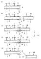
次に、図3を参照しながら第1のホイストビーム2Aに対して第2のホイストビーム2Bをつなぐ手順について説明する。
図3(a)に示すように、天井梁1に対して第1のホイストビーム2Aが予め取り付けられている。そして、第1のホイストビーム2Aの上側及び下側フランジ部6、7のそれぞれの端部には、上側及び下側プレート部11、12がアーク溶接等を用いて固定されている。なお、フランジ部6、7に対するプレート部11、12の固定作業は、第1のホイストビーム2Aを天井梁1に対して取り付ける前に、例えばホイストビーム製造工場などにおいて予め行うことができる。これにより、高所溶接作業(現場溶接作業)を行わずに、フランジ部6、7に対してプレート部11、12を固定することができる。なお、第1のホイストビーム2Aを天井梁1に取り付けた後、この第1のホイストビーム2Aのフランジ部6、7に対してプレート部11、12のそれぞれをアーク溶接等により固定する構成とすることも可能である。
【0022】
次いで、図3(b)に示すように、第1のホイストビーム2Aの凸部9と第2のホイストビーム2Bの凹部10とを嵌合するように、第1のホイストビーム2Aに対して第2のホイストビーム2Bを位置決めする。ここで、第1のホイストビーム2Aの端部には上側及び下側フランジ部11、12が固定されているため、第2のホイストビーム2Bの端部をこの上側及び下側フランジ部11、12の間に挿入することで、第1のホイストビーム2Aと第2のホイストビーム2Bとを位置決めしつつつなぐことができる。そして、第2のホイストビーム2Bの凹部10に第1のホイストビーム2Aの凸部9が配置され、互いの位置決めが終了したら、図3(c)に示すように、ボルト13を用いて上側プレート部11と第2のホイストビーム2Bの上側フランジ部6とを締結する。以上説明した工程により、第1及び第2のホイストビーム2A、2Bの結合が終了する。
【0023】
なお、ここでは、第1のホイストビーム2Aにプレート部11、12を予め固定しておき、これに対して第2のホイストビーム2Bを接続するように説明したが、第2のホイストビーム2Bにプレート部11をボルト13を用いて取り付けておき、この第2のホイストビーム2Bを天井梁1に取り付けられている第1のホイストビーム2Aに対して連結する構成であってもよい。この場合、天井梁1において、第1のホイストビーム2Aとプレート部11との溶接作業が行われる構成となる。
【0024】
第1のホイストビーム2Aから第2のホイストビーム2Bを分離する際には、図3(d)に示すように、ボルト13による上側プレート部11と第2のホイストビーム2Bの上側フランジ部6との締結を解除する。そして、図3(e)に示すように、第2のホイストビーム2Bを例えばY軸方向に移動することにより、第1のホイストビーム2Aに対して第2のホイストビーム2Bを容易に分離することができる。
【0025】
ここで、分離される(搬送される)ホイストビームは第2のホイストビーム2Bであって、この第2のホイストビーム2Bに凹部10が形成されている構成である。複数のホイストビームをつなぐ際、これらホイストビームのそれぞれはほぼ同じ長さに設定されている場合が多いため、凹部10が形成されているホイストビームは、凸部9が形成されているホイストビームに対して軽量である。そこで、分離される側(搬送される側)のホイストビーム(すなわち第2のホイストビーム2B)に凹部10を設けておくことにより、軽量なホイストビームを搬送することになるので、作業性を向上することができる。
【0026】
以上説明したように、第1のホイストビーム2Aと第2のホイストビーム2Bとをつなげる際、第1のホイストビーム2Aのウェブ部8に凸部9を設けるとともに、第2のホイストビーム2Bのウェブ部8に凹部10を設け、この凹部10に対して凸部9を嵌め合わせるようにして配置したので、ホイストビーム2の撓み変形に起因する剪断力が大きくなっても、凸部9及び凹部10の当接により前記剪断力を受けることができる。また、第1及び第2のホイストビーム2A、2Bのフランジ部6、7どうしをプレート部11、12で接続したので、ホイストビーム2A、2Bの端部に作用する曲げ応力をプレート部11、12で受けることができる。したがって、ホイストクレーン3やホイストクレーン3に搬送される搬送物5の重量が大きくなっても、第1及び第2のホイストビーム2A、2Bの端部間に段差が生じたり、走行経路が屈曲する等の不都合の発生を抑えることができ、ホイストクレーン3を円滑に走行させることができる。
【0027】
また、凸部9及び凹部10を略円弧状に形成したので、ホイストビーム2の撓みに起因して凸部9と凹部10との相対位置が変化しても、凸部9や凹部10には過剰な応力が作用しない。したがって、凸部9や凹部10の削れ等の破損といった不都合の発生を抑えることができる。
【0028】
また、上側プレート部11の他端部をボルト13により第2のホイストビーム2Bに対して締結する構成としたので、この締結及び締結解除により、高所溶接作業を伴うことなく、第1及び第2のホイストビーム2A、2Bの結合・分離作業を容易に行うことができる。
【0029】
なお、本実施形態では、凸部9及び凹部10のそれぞれは1つずつ設けられている構成であるが、任意の複数ずつ設けられている構成であってもよい。この場合、第1のホイストビーム2Aのウェブ部8の端部は複数の凸部9により略鋸刃状に形成され、同様に、第2のホイストビーム2Bのウェブ部8の端部も複数の凹部10により略鋸刃状に形成される。
【0030】
なお、本実施形態において、ホイストビーム2はI形鋼により構成されているが、H形鋼やみぞ形鋼であってもよい。あるいは、ウェブ部に対してフランジアングルを取り付けた組立材であってもよい。更には、ウェブ部に対してフランジ部を溶接により接続した形鋼であってもよい。すなわち、ホイストビーム2はフランジ部とウェブ部とを有する形鋼であればよい。
【0031】
なお、上記実施形態では、ホイストビーム2は水平面に平行に設けられているように説明したが、水平面に対して傾斜して設けられていてもよい。更に、ホイストビーム2は直線状に設けられているように説明したが、途中でカーブしていてもよい。
【0032】
図4は第1のホイストビーム2Aと第2のホイストビーム2Bとをつなぐ手順の他の実施形態を説明するための図である。図4(a)に示すように、2つの第1のホイストビーム2A、2Aが所定の間隔をあけて予め天井梁1に取り付けられている。ここで、第1のホイストビーム2A、2Aの間の距離は、第2のホイストビーム2Bの長さに対応して予め設定されている。ここでは、第1のホイストビーム2A、2Aの上側及び下側フランジ部6、7のそれぞれの端部に、上側及び下側プレート部11、12がアーク溶接等を用いて固定されている。
そして、図4(b)に示すように、第1のホイストビーム2A、2Aの間に第2のホイストビーム2Bが取り付けられる。第2のホイストビーム2Bを取り付ける際には、第2のホイストビーム2Bを、例えば紙面手前側(−Y側)から、2つの第1のホイストビーム2A、2Aの間に搬入し、第2のホイストビーム2Bの凹部10に第1のホイストビーム2Aの凸部9を配置する。そして、ボルト13を用いて上側プレート部11と第2のホイストビーム2Bの上側フランジ部6とを締結することにより、第2のホイストビーム2Bが第1のホイストビーム2A、2Aに取り付けられる。ここで、第2のホイストビーム2Bはその両端を第1のホイストビーム2A、2Aに対して固定されるので、第2のホイストビーム2B自体は天井梁1(あるいは吊材)に接続される必要がない。
また、第2のホイストビーム2Bを外す際には、ボルト13による締結を解除した後、第2のホイストビーム2Bを例えば紙面手前側(−Y側)に移動することで、第2のホイストビーム2Bを容易に外すことができる。
【0033】
このように、本発明によれば、天井梁1や吊材などに予め取り付けられている第1のホイストビーム2A、2Aに対して第2のホイストビーム2Bを容易に取り付け・取り外しすることができる。この場合、第2のホイストビーム2Bに関しては天井梁1(あるいは吊材)に対する接続が不要となるため、良好な作業性が得られる。
【0034】
なお、図4を用いた説明では、凸部9を有する第1のホイストビーム2A、2Aが天井梁1に予め取り付けられているように説明したが、凹部10を有する第2のホイストビーム2B、2Bを天井梁1に予め取り付けておき、この2つの第2のホイストビーム2B、2Bの間に対して第1のホイストビーム2Aを取り付け・取り外しするようにしてもよい。
【0035】
【発明の効果】
本発明の継手構造によれば、ホイストビームに大きな剪断力や曲げ応力が作用しても、これら力を良好に受けることができ、ホイストクレーンを円滑に走行させることができる。また、現場溶接作業を不要とすることができるので、現場でのホイストビームの設置作業性を大きく向上することができる。
【図面の簡単な説明】
【図1】本発明に係るホイストビームを備えた搬送システム全体を示す概略構成図である。
【図2】本発明のホイストビームの継手構造を示す図である。
【図3】ホイストビームどうしをつなぐ手順の一例を示す模式図である。
【図4】ホイストビームどうしをつなぐ手順の他の例を示す模式図である。
【符号の説明】
2…ホイストビーム、2A…第1のホイストビーム、
2B…第2のホイストビーム、6…上側フランジ部、7…下側フランジ部、
8…ウェブ部、9…凸部、10…凹部、11…上側プレート部、
12…下側プレート部、13…ボルト(締結部材)、T…継手構造[0001]
TECHNICAL FIELD OF THE INVENTION
The present invention relates to a hoist beam joint structure.
[0002]
[Prior art]
When a conveyed object is transported in a factory or the like, a hoist crane that travels while being hung on a hoist beam, which is a traveling rail provided on a ceiling, may be used. The following patent document discloses a technique relating to a joint structure for connecting hoist beams. This technology attaches a fitting to the flange portion of the hoist beam, and when the hoist crane moves from the first hoist beam to the second hoist beam, holds down the end of the hoist beam that is going to bend by the fitting fitting. An object of the present invention is to suppress the occurrence of a step between the ends of the hoist beam caused by the deflection of the hoist beam, and to make the hoist crane run smoothly.
[0003]
[Patent Document 1]
JP 2001-302173 A
[Problems to be solved by the invention]
By the way, the above-mentioned prior art has the following problems.
When the weight of the hoist crane or the load conveyed by the hoist crane increases, the end of the hoist beam tends to bend significantly. In this case, since the joint fitting in the related art is a plate-shaped member, it is impossible to suppress large bending deformation of the end portion of the hoist beam, and there is a possibility that the joint fitting may be deformed or damaged. That is, the strength of the conventional fitting is insufficient, and a problem has arisen that the shearing force or bending stress acting on the hoist beam cannot be sufficiently received.
[0005]
The present invention has been made in view of such circumstances, and when a hoist crane moves between hoist beams, even if the weight of the hoist crane or the load conveyed by the hoist crane increases, the deflection of the hoist beam is prevented. An object of the present invention is to provide a joint structure of a hoist beam capable of suppressing deformation and favorably generating a step between ends of the hoist beam.
[0006]
[Means for Solving the Problems]
In order to solve the above problems, a joint structure for a hoist beam according to the present invention is a joint structure for connecting hoist beams having a flange portion and a web portion, wherein a convex portion is provided at an end of the web portion of the first hoist beam. And a concave portion is provided at an end of a web portion of the second hoist beam connected to the first hoist beam, and the convex portion is arranged in the concave portion.
[0007]
According to the present invention, when connecting the first hoist beam and the second hoist beam, a convex portion is provided on the web portion of the first hoist beam, and a concave portion is provided on the web portion of the second hoist beam. Since the convex portion is arranged so as to be fitted to the concave portion, even if the shearing force acting on the end of the hoist beam becomes large, the convex portion and the concave portion may receive the shearing force. it can. Therefore, even if the weight of the hoist crane or the load conveyed by the hoist crane increases, it is possible to suppress the occurrence of a step between the ends of the first and second hoist beams, and to make the hoist crane smooth. Can be run.
[0008]
In the joint structure for a hoist beam according to the present invention, the concave portion has a shape along the convex portion, and each of the convex portion and the concave portion is formed in a substantially arc shape. According to the present invention, since the convex portion and the concave portion have no corner and are formed in a substantially arc shape (curved shape), even if the relative position of the convex portion to the concave portion changes due to the deflection of the hoist beam. Excessive stress does not act on the projections and depressions. Therefore, it is possible to suppress the occurrence of inconvenience such as breakage such as scraping of the convex portions and concave portions.
[0009]
The hoist beam joint structure of the present invention is characterized in that the joint structure has a plate portion for connecting the flange portions of the first and second hoist beams. According to the present invention, since the flange portions of the first and second hoist beams are connected to each other by the plate portion, the plate portion can receive bending stress acting on the end portion of the hoist beam. Therefore, it is possible to suppress the occurrence of the inconvenience that the traveling path of the hoist crane is bent between the first and second hoist beams, and the hoist crane can travel smoothly. Also, this plate portion can be used as a positioning member when connecting the first hoist beam and the second hoist beam, thereby improving workability when connecting the first and second hoist beams. Can be.
[0010]
In the joint structure for a hoist beam according to the present invention, the plate portion is fixed to one flange portion of the first and second hoist beams, and is fastened to the other flange portion via a fastening member. Features. According to the present invention, the plate portion is fastened to the flange portion of one of the first and second hoist beams. Can be easily combined and separated from the second hoist beam.
[0011]
In the hoist beam joint structure of the present invention, the thickness tp of the plate portion is set so as to satisfy a condition of tp ≧ 1.5tf with respect to the thickness tf of the flange portion. I do. According to the present invention, by setting the plate thickness tp of the plate portion subjected to the bending stress of the hoist beam to 1.5 times or more the plate thickness tf of the flange portion, the plate portion has sufficient strength, The bending stress of the hoist beam can be received without causing inconvenience such as deformation and breakage.
[0012]
BEST MODE FOR CARRYING OUT THE INVENTION
Hereinafter, the joint structure of the hoist beam of the present invention will be described with reference to the drawings. FIG. 1A is a schematic configuration diagram showing the entire transfer system having a joint structure of a hoist beam according to the present invention. FIG. 1B is a diagram of FIG. 1A viewed from the front side (+ X side).
In FIG. 1, the transport system S includes a
[0013]
As shown in FIG. 1 (b), the
[0014]
The hoist
[0015]
FIG. 2 is an enlarged view showing a joint structure T connecting the first and second hoist
[0016]
By arranging the
[0017]
Further, the joint structure T includes an
[0018]
Here, as shown in FIG. 2B, two
[0019]
By connecting the
[0020]
In the present embodiment, the thickness tp of the
[0021]
Next, a procedure for connecting the second hoist
As shown in FIG. 3A, the first hoist
[0022]
Next, as shown in FIG. 3 (b), the first hoist
[0023]
Here, the
[0024]
When separating the second hoist
[0025]
Here, the hoist beam to be separated (conveyed) is the second hoist
[0026]
As described above, when connecting the first hoist
[0027]
Further, since the
[0028]
In addition, since the other end of the
[0029]
In the present embodiment, each of the
[0030]
In this embodiment, the hoist
[0031]
In the above embodiment, the hoist
[0032]
FIG. 4 is a diagram for explaining another embodiment of a procedure for connecting the first hoist
Then, as shown in FIG. 4B, the second hoist
When removing the second hoist
[0033]
As described above, according to the present invention, the second hoist
[0034]
In the description with reference to FIG. 4, the first hoist
[0035]
【The invention's effect】
ADVANTAGE OF THE INVENTION According to the joint structure of this invention, even if a big shearing force or bending stress acts on a hoist beam, these forces can be received well and a hoist crane can run smoothly. In addition, since the on-site welding operation can be omitted, the workability of installing the hoist beam on the site can be greatly improved.
[Brief description of the drawings]
FIG. 1 is a schematic configuration diagram showing an entire transport system including a hoist beam according to the present invention.
FIG. 2 is a view showing a joint structure of a hoist beam of the present invention.
FIG. 3 is a schematic diagram showing an example of a procedure for connecting hoist beams.
FIG. 4 is a schematic view showing another example of a procedure for connecting hoist beams.
[Explanation of symbols]
2 ... hoist beam, 2A ... first hoist beam,
2B: second hoist beam, 6: upper flange portion, 7: lower flange portion,
8 web part, 9 convex part, 10 concave part, 11 upper plate part,
12: Lower plate part, 13: Bolt (fastening member), T: Joint structure
Claims (5)
第1のホイストビームのウェブ部の端部に凸部を設けるとともに、該第1のホイストビームにつなぐ第2のホイストビームのウェブ部の端部に凹部を設け、
前記凹部に前記凸部を配置したことを特徴とするホイストビームの継手構造。A joint structure for connecting hoist beams having a flange portion and a web portion,
A convex portion is provided at an end of the web portion of the first hoist beam, and a concave portion is provided at an end portion of the web portion of the second hoist beam connected to the first hoist beam;
A hoist beam joint structure, wherein the convex portion is arranged in the concave portion.
Priority Applications (1)
| Application Number | Priority Date | Filing Date | Title |
|---|---|---|---|
| JP2003022526A JP2004231364A (en) | 2003-01-30 | 2003-01-30 | Joint structure for hoisting beam |
Applications Claiming Priority (1)
| Application Number | Priority Date | Filing Date | Title |
|---|---|---|---|
| JP2003022526A JP2004231364A (en) | 2003-01-30 | 2003-01-30 | Joint structure for hoisting beam |
Publications (1)
| Publication Number | Publication Date |
|---|---|
| JP2004231364A true JP2004231364A (en) | 2004-08-19 |
Family
ID=32951580
Family Applications (1)
| Application Number | Title | Priority Date | Filing Date |
|---|---|---|---|
| JP2003022526A Pending JP2004231364A (en) | 2003-01-30 | 2003-01-30 | Joint structure for hoisting beam |
Country Status (1)
| Country | Link |
|---|---|
| JP (1) | JP2004231364A (en) |
Cited By (5)
| Publication number | Priority date | Publication date | Assignee | Title |
|---|---|---|---|---|
| CN103112779A (en) * | 2013-02-08 | 2013-05-22 | 成都西部泰力起重机有限公司 | Segmented girder connecting device of multi-pivot overhang crane |
| WO2014118437A1 (en) * | 2013-01-31 | 2014-08-07 | Konecranes Plc | Method to form a rail joint, and a rail joint |
| CN104401333A (en) * | 2014-12-06 | 2015-03-11 | 湘潭市恒欣实业有限公司 | Telescopic rail for rail type aerial passenger device |
| CN107687206A (en) * | 2017-09-30 | 2018-02-13 | 中铁大桥勘测设计院集团有限公司 | The I-shaped fixture of displacement connectors |
| CN107934766A (en) * | 2017-12-25 | 2018-04-20 | 浙江邦博机械有限公司 | A kind of main beam structure of more fulcrum suspension cranes |
-
2003
- 2003-01-30 JP JP2003022526A patent/JP2004231364A/en active Pending
Cited By (7)
| Publication number | Priority date | Publication date | Assignee | Title |
|---|---|---|---|---|
| WO2014118437A1 (en) * | 2013-01-31 | 2014-08-07 | Konecranes Plc | Method to form a rail joint, and a rail joint |
| CN104968596A (en) * | 2013-01-31 | 2015-10-07 | 科恩起重机有限公司 | Method to form a rail joint, and a rail joint |
| US9695555B2 (en) | 2013-01-31 | 2017-07-04 | Konecranes Global Corporation | Method to form a rail joint, and a rail joint |
| CN103112779A (en) * | 2013-02-08 | 2013-05-22 | 成都西部泰力起重机有限公司 | Segmented girder connecting device of multi-pivot overhang crane |
| CN104401333A (en) * | 2014-12-06 | 2015-03-11 | 湘潭市恒欣实业有限公司 | Telescopic rail for rail type aerial passenger device |
| CN107687206A (en) * | 2017-09-30 | 2018-02-13 | 中铁大桥勘测设计院集团有限公司 | The I-shaped fixture of displacement connectors |
| CN107934766A (en) * | 2017-12-25 | 2018-04-20 | 浙江邦博机械有限公司 | A kind of main beam structure of more fulcrum suspension cranes |
Similar Documents
| Publication | Publication Date | Title |
|---|---|---|
| JP4078367B2 (en) | Cable-stayed cable fixing structure | |
| JP2010095898A (en) | Trussed setting beam | |
| JP2004231364A (en) | Joint structure for hoisting beam | |
| JP6769549B2 (en) | Beam joining method, beam joining structure, and support members | |
| JP2007032098A (en) | Method of connecting between large beam and small beam, and connection structure between the same | |
| JP2005282019A (en) | Joint structure of steel framed small beam | |
| JP5856882B2 (en) | Passenger conveyor and passenger conveyor assembly method | |
| JP2012097496A (en) | Buckling restraining brace | |
| JPH07216988A (en) | Joint structure of steel framed column-steel framed beam | |
| JPH10237957A (en) | Joint structure of steel material and manufacture of joint member used therefor | |
| JP4528177B2 (en) | Floor forming method and floor forming structure | |
| JPH11324129A (en) | Joint structure of pillar to beam and building unit | |
| JP4130164B2 (en) | Beam connection structure | |
| KR101476150B1 (en) | Construction method for rahmen bridge using pre-torsion girder | |
| JP3518742B2 (en) | Joint structure of truss structure | |
| JP6063807B2 (en) | Welding method | |
| JP4452518B2 (en) | Composite member joining structure | |
| JP5568045B2 (en) | Buckling restraint brace | |
| JP3170413B2 (en) | Monorail suspension and its construction method | |
| KR101413269B1 (en) | Light shape steel and assembly system using the same | |
| JP6775327B2 (en) | Structure of pillar joint | |
| JP2024078314A (en) | Fixation member, fixation structure for reinforcement member to structure, and method for fixing reinforcement member to structure | |
| JP4494671B2 (en) | Structure and manufacturing method thereof | |
| JP2000086148A (en) | Guide rail suspension device for conveyance | |
| JP3096284B2 (en) | Structural material holder |
Legal Events
| Date | Code | Title | Description |
|---|---|---|---|
| A621 | Written request for application examination |
Free format text: JAPANESE INTERMEDIATE CODE: A621 Effective date: 20051220 |
|
| A977 | Report on retrieval |
Effective date: 20081017 Free format text: JAPANESE INTERMEDIATE CODE: A971007 |
|
| A131 | Notification of reasons for refusal |
Free format text: JAPANESE INTERMEDIATE CODE: A131 Effective date: 20081111 |
|
| A02 | Decision of refusal |
Free format text: JAPANESE INTERMEDIATE CODE: A02 Effective date: 20090310 |