JP2004231122A - Electric steering lock device - Google Patents
Electric steering lock device Download PDFInfo
- Publication number
- JP2004231122A JP2004231122A JP2003024681A JP2003024681A JP2004231122A JP 2004231122 A JP2004231122 A JP 2004231122A JP 2003024681 A JP2003024681 A JP 2003024681A JP 2003024681 A JP2003024681 A JP 2003024681A JP 2004231122 A JP2004231122 A JP 2004231122A
- Authority
- JP
- Japan
- Prior art keywords
- lock
- stopper
- plate
- main body
- guide portion
- Prior art date
- Legal status (The legal status is an assumption and is not a legal conclusion. Google has not performed a legal analysis and makes no representation as to the accuracy of the status listed.)
- Granted
Links
Images

Classifications
-
- B—PERFORMING OPERATIONS; TRANSPORTING
- B60—VEHICLES IN GENERAL
- B60R—VEHICLES, VEHICLE FITTINGS, OR VEHICLE PARTS, NOT OTHERWISE PROVIDED FOR
- B60R25/00—Fittings or systems for preventing or indicating unauthorised use or theft of vehicles
- B60R25/01—Fittings or systems for preventing or indicating unauthorised use or theft of vehicles operating on vehicle systems or fittings, e.g. on doors, seats or windscreens
- B60R25/02—Fittings or systems for preventing or indicating unauthorised use or theft of vehicles operating on vehicle systems or fittings, e.g. on doors, seats or windscreens operating on the steering mechanism
- B60R25/021—Fittings or systems for preventing or indicating unauthorised use or theft of vehicles operating on vehicle systems or fittings, e.g. on doors, seats or windscreens operating on the steering mechanism restraining movement of the steering column or steering wheel hub, e.g. restraining means controlled by ignition switch
- B60R25/0215—Fittings or systems for preventing or indicating unauthorised use or theft of vehicles operating on vehicle systems or fittings, e.g. on doors, seats or windscreens operating on the steering mechanism restraining movement of the steering column or steering wheel hub, e.g. restraining means controlled by ignition switch using electric means, e.g. electric motors or solenoids
- B60R25/02153—Fittings or systems for preventing or indicating unauthorised use or theft of vehicles operating on vehicle systems or fittings, e.g. on doors, seats or windscreens operating on the steering mechanism restraining movement of the steering column or steering wheel hub, e.g. restraining means controlled by ignition switch using electric means, e.g. electric motors or solenoids comprising a locking member radially and linearly moved towards the steering column
-
- Y—GENERAL TAGGING OF NEW TECHNOLOGICAL DEVELOPMENTS; GENERAL TAGGING OF CROSS-SECTIONAL TECHNOLOGIES SPANNING OVER SEVERAL SECTIONS OF THE IPC; TECHNICAL SUBJECTS COVERED BY FORMER USPC CROSS-REFERENCE ART COLLECTIONS [XRACs] AND DIGESTS
- Y10—TECHNICAL SUBJECTS COVERED BY FORMER USPC
- Y10T—TECHNICAL SUBJECTS COVERED BY FORMER US CLASSIFICATION
- Y10T70/00—Locks
- Y10T70/50—Special application
- Y10T70/5611—For control and machine elements
- Y10T70/5646—Rotary shaft
- Y10T70/565—Locked stationary
- Y10T70/5655—Housing-carried lock
- Y10T70/5664—Latching bolt
-
- Y—GENERAL TAGGING OF NEW TECHNOLOGICAL DEVELOPMENTS; GENERAL TAGGING OF CROSS-SECTIONAL TECHNOLOGIES SPANNING OVER SEVERAL SECTIONS OF THE IPC; TECHNICAL SUBJECTS COVERED BY FORMER USPC CROSS-REFERENCE ART COLLECTIONS [XRACs] AND DIGESTS
- Y10—TECHNICAL SUBJECTS COVERED BY FORMER USPC
- Y10T—TECHNICAL SUBJECTS COVERED BY FORMER US CLASSIFICATION
- Y10T70/00—Locks
- Y10T70/50—Special application
- Y10T70/5889—For automotive vehicles
- Y10T70/5956—Steering mechanism with switch
Landscapes
- Engineering & Computer Science (AREA)
- Mechanical Engineering (AREA)
- Lock And Its Accessories (AREA)
Abstract
Description
【0001】
【発明の属する技術分野】
本発明は、自動車等の車両に適用される電動ステアリングロック装置に関する。
【0002】
【従来の技術】
自動車等の車両では、盗難防止装置として、例えば、いわゆる電動ステアリングロック装置を備えている。この電動ステアリングロック装置は、例えば、車両のステアリングポストに組み付けられるロックボディを備えている。このロックボディは、駆動手段を収納する本体部と、この本体部からステアリングシャフト側へ向けて突設された筒状のガイド部とを一体に有している。この本体部の内部において、駆動手段とされるモーターにはカム部が連結されており、モーターの正・逆回転に対応してカム部が回動するようになっている。そして、ガイド部の筒内には、カム部の回動に対応して移動可能とされると共にスプリングによりステアリングシャフト側へ付勢されたロックストッパと、一端部がロックストッパに係合したロックバーとが配設されている。
【0003】
上記構成の電動ステアリングロック装置では、ロックバーの先端部がステアリングシャフト側へ突出してそのステアリングシャフトを回動不能にロックし、カム部によりロックストッパ及びロックバーをスプリングの付勢力に抗してステアリングシャフトとは反対方向へ移動させて、ステアリングシャフトに対するロックバーの係合を解除するようになっている。
【0004】
一方、キーにより操作される一般のステアリングロック装置において、上記電動ステアリングロック装置と基本的に同一の構成とされているものもある。このようなステアリングロック装置では、キーが挿入されるキーシリンダが本体部に収容されており、キーシリンダに挿入されたキーの回動操作によりカムシャフトのカム部が回動される構成とされている。そして、このカム部の回動に対応して、ロックストッパ及びロックバーが、ガイド部の筒内を移動するようになっている。
【0005】
ところで、車両急減速時等に、運転者の膝がロックボディの本体部もしくはガイド部に強く当たって大きな衝撃を受けることがある。このため、ロックボディの本体部もしくはガイド部が所定値以上の衝撃力を受けた際に、ガイド部の中間部が破損することで、運転者が受ける衝撃を軽減する構成としたステアリングロック装置が、本出願人により提案されている(特許文献1参照)。
【0006】
さらに、この特許文献1に開示されているステアリングロック装置では、ロックボディのガイド部の破損に伴い、ロックストッパとロックバーとの係合が外れてロックバーが移動可能になり、走行中の車両のステアリングシャフトがロックされることを阻止する阻止手段が設けられている。すなわち、ロックバー側へ付勢されると共に通常時は移動が規制された係合部材をガイド部の先端側に設け、ガイド部の中間部の破損に伴って、その規制を解除して係合部材を移動させ、ロックバーに設けられた係合部に係合させることでロックバーの移動を規制する構成とされている。
【0007】
しかも、この構成によれば、車両駐車時において不正行為によりロックボディが破壊された場合にも、係合部材によりロックバーの移動を規制することが可能であり、ロックバーによるステアリングシャフトのロック状態を維持することができる(所謂「デッドロック機構」)。
【0008】
ところが、上記特許文献1に開示されているステアリングロック装置では、係合部材および係合部材の移動を規制する規制部材がロックボディの外部に露出しているため、ロックボディを破壊する前に予め係合部材を固定することで、係合部材がロックバーに係合することを阻止される恐れがあった。
【0009】
このため、このような係合部材および規制部材をロックボディの内部に設置することで盗難防止性を高めたステアリングロック装置が、本出願人により提案されている(特許文献2参照)。
【0010】
この特許文献2に開示されているステアリングロック装置では、カムシャフトはガイド部内に設けられており、ロックボディが破壊された場合には、本体部とガイド部とが分断されるようになっている。そして、ガイド部とカムシャフトとの間に配置されると共に一端が本体部に固定された規制部材によって係合部材の移動が規制されている。このため、本体部とガイド部との分断に伴って規制部材が除去されるので、係合部材がカムシャフト側へ移動し、カムシャフトに設けられた係合孔に係合する。これにより、カムシャフト、ロックストッパ及びロックバーの移動が規制される。
【0011】
しかしながら、上記特許文献2のステアリングロック装置では、本体部とガイド部との分断に伴って規制部材が本体部と共に除去されるため、ガイド部とカムシャフトとの間には隙間が生じることになる。このため、この隙間から係合部材の位置が特定されて、何らかの方法でカムシャフトに係合した係合部材が外される可能性があり、これを防止する対策が必要とされている。
【0012】
【特許文献1】
特開平7−9944号公報
【特許文献2】
特開2000−225922号公報
【0013】
【発明が解決しようとする課題】
本発明は、上記事実を考慮して、車両駐車中にロックボディが破壊された場合には、ステアリングシャフトのロック状態を維持し、しかも、不正行為によるロック状態の解除が困難で盗難防止性が高い電動ステアリングロック装置を得ることが目的である。
【0014】
【課題を解決するための手段】
上記目的を達成するために、請求項1記載の発明に係る電動ステアリングロック装置は、駆動源が収納される本体部を有すると共に、前記本体部から車両のステアリングシャフトへ向けて突設された筒状のガイド部を有するロックボディと、前記ロックボディに所定値以上の衝撃が作用した際に前記ロックボディを分断可能とする連結部と、前記駆動源からの駆動力によって移動するロックストッパと、基端部が前記ロックストッパに連結されると共に前記ガイド部内に前記ロックストッパと一体に移動可能に設けられ、前記ロックストッパが前記ロックボディのガイド部側へ移動された状態では先端部が前記ガイド部の先端から前記ステアリングシャフトの方向へ突出して前記ステアリングシャフトをロックし、前記ロックストッパが前記ロックボディの本体部側へ移動された状態では前記先端部が前記ステアリングシャフトとは反対方向へ移動して前記ステアリングシャフトの前記ロックを解除するロックバーと、貫通孔を有し、前記ガイド部と前記ロックストッパとの間に前記本体部の方向へ移動可能に設けられると共に付勢手段により前記本体部側へ付勢され、通常時は前記本体部に当接することにより前記本体部側への移動を阻止されたロックプレートと、前記ガイド部に前記ロックストッパの移動方向と交差する方向へ移動可能に設けられ、付勢手段により前記ロックストッパ側へ付勢されると共に前記ロックプレートの前記貫通孔の孔縁に当接することにより前記ロックストッパ側への移動を阻止されたロックピンと、前記ロックストッパが前記ロックボディのガイド部側へ移動された状態で、前記ロックストッパの前記ロックプレートを挟んで前記ロックピンと対向する位置に形成され、前記ロックピンが嵌入可能とされた嵌入凹部と、を備えたことを特徴としている。
【0015】
請求項1に記載の電動ステアリングロック装置では、車両駐車時にはロックストッパがロックボディのガイド部側へ移動されることで、ロックバーの先端部がガイド部の先端から突出してステアリングシャフトをロックしている。
【0016】
このロック状態において、不正行為によりロックボディが破壊され、ロックボディに所定値以上の衝撃が作用した際には、ロックボディは連結部を起点として分断される。このため、本体部により本体部側への移動を阻止されていたロックプレートが、付勢手段の付勢力により移動する。そして、付勢手段によりロックストッパ側へ付勢されると共にロックプレートに形成された貫通孔の孔縁に当接することで移動を阻止されていたロックピンが、ロックプレートの貫通孔に挿通してロックストッパに形成された嵌入凹部に嵌入する。これにより、ロックストッパの移動が阻止されるため、基端部がロックストッパに連結されたロックバーの移動も制限される。したがって、車両駐車中に不正行為によりロックボディが破壊されても、ステアリングシャフトのロックが解除されることが防止される。
【0017】
しかも、ロックピンがロックプレートの貫通孔に挿通した状態で、ロックストッパの嵌入凹部に嵌入するため、ロックプレートのガイド部に対する移動も制限され、ロックプレートがガイド部から引き抜かれることが防止される。これにより、ガイド部とロックストッパの間はロックプレートにより塞がれた状態となるため、ガイド部とロックストッパとの間からロックピンを破壊してステアリングシャフトのロックを解除することが困難になり盗難防止性が向上する。
【0018】
このように、請求項1記載の電動ステアリングロック装置では、車両駐車中にロックボディが破壊された場合には、ステアリングシャフトのロック状態を維持し、しかも、不正行為によるロック状態の解除が困難で盗難防止性が高い。
【0019】
請求項2記載の発明に係る電動ステアリングロック装置は、請求項1記載の電動ステアリングロック装置において、前記ロックプレート及び前記ロックプレートを付勢する前記付勢手段と、前記ロックピン及び前記ロックピンを付勢する前記付勢手段とが前記ガイド部の内部に露出しない状態で設けられる、ことを特徴としている。
【0020】
請求項2記載の発明に係る電動ステアリングロック装置では、ロックピン、ロックプレート及びこれらを付勢する付勢手段がガイド部の内部に露出しない状態で設けられている。このため、外観からはこのロックプレート及びロックピンの機構や位置が把握されにくい。
【0021】
また、盗難者などによりロックボディに所定値以上の衝撃が加えられて、ロックボディが分断された場合にも、ガイド部とロックストッパとの間がロックプレートにより塞がれてガイド部の内部が露出しないため、ロックピンの機構や位置が把握されにくい。
【0022】
一方、ロックピンの位置が特定されても、ガイド部(一般に金属製)を破壊してロックストッパの嵌入凹部からロックピンを排除しなければ、ロックバーによるステアリングシャフトのロック状態を解除することができない。このため、ロック状態の解除には相当の時間を要することになり、さらに盗難防止性が向上する。
【0023】
このように、請求項2記載の電動ステアリングロック装置では、さらに車両駐車時の盗難防止性が向上する。
【0024】
請求項3記載の発明に係る電動ステアリングロック装置は、請求項1記載または請求項2記載の電動ステアリングロック装置において、前記ロックストッパが前記ロックボディの本体部側へ移動された状態で、前記ロックストッパの前記ロックプレートを挟んで前記ロックピンと対向する位置に形成され、前記ロックピンが嵌入可能とされた第2の嵌入凹部を有する、ことを特徴としている。
【0025】
請求項3記載の電動ステアリングロック装置では、車両走行時には、ロックストッパがロックボディの本体部側へ移動されることで、ロックバーの先端部がステアリングシャフトとは反対方向へ移動してステアリングシャフトのロックが解除されている。
【0026】
このロックが解除された状態において、車両の急制動に伴い乗員の膝などがロックボディに衝突して、ロックボディに所定値以上の衝撃が作用した際には、ロックボディは連結部を起点として分断される。これにより、乗員の膝などがロックボディから受ける衝撃が軽減される。
【0027】
さらにこのとき、本体部により本体部側への移動を阻止されていたロックプレートが、付勢手段の付勢力により移動する。そして、付勢手段によりロックストッパ側へ付勢されると共にロックプレートに形成された貫通孔の孔縁に当接することで移動を阻止されていたロックピンが、ロックプレートの貫通孔に挿通してロックストッパに形成された第2の嵌入凹部に嵌入する。これにより、ロックストッパの移動が阻止されるため、基端部がロックストッパに連結されたロックバーの移動も制限される。したがって、車両走行中にロックボディが破壊されても、ステアリングシャフトがロックバーによりロックされることが防止される。
【0028】
このように、請求項3記載の電動ステアリングロック装置では、車両走行時にロックボディが破損した場合に、ステアリングシャフトのアンロック状態が維持され、車両走行時の安全性が向上する。
【0029】
請求項4記載の発明に係る電動ステアリングロック装置は、請求項1乃至請求項3の何れか一項に記載の電動ステアリングロック装置において、前記ロックストッパの前記連結部に対応する位置に設けられ、前記ロックボディの前記分断の際に前記ロックストッパ自体を分断可能とする脆弱部を有する、ことを特徴としている。
【0030】
請求項4記載の電動ステアリングロック装置では、ロックボディに所定値以上の衝撃が作用して、ロックボディが連結部を起点として分断された際には、ロックストッパ自体が、連結部に対応する位置に設けられた脆弱部を起点として分断される。
【0031】
これにより、不正行為によりロックボディが破壊され、ロックピンによりロックストッパの移動が阻止された状態において、ロックストッパを挟持することが困難となるため、ロックストッパが強制的に引き抜かれてロックが解除されることを防止できる。
【0032】
また、車両走行時に乗員の膝などがロックボディに衝突した場合に、乗員の膝などがロックストッパから衝撃を受けることが防止され、さらに乗員の安全性が向上する。
【0033】
このように、請求項4記載の電動ステアリングロック装置では、さらに車両駐車時の盗難防止制と車両走行時の安全性が向上する。
【0034】
請求項5記載の発明に係る電動ステアリングロック装置は、請求項1乃至請求項4の何れか一項に記載の電動ステアリングロック装置において、前記ロックプレートは、前記本体部に固定される固定プレートと、中央部に前記貫通孔を有し前記ガイド部の内壁と前記ロックストッパとの間に前記固定プレートの方向へ移動可能に設けられると共に前記付勢手段により前記固定プレート側へ付勢された可動プレートと、に分割して構成され、前記ロックボディの前記連結部に対応する位置において、前記固定プレートの端縁に前記可動プレートの端縁が係合することで前記可動プレートの前記固定プレート側への移動が阻止される、ことを特徴としている。
【0035】
請求項5記載の電動ステアリングロック装置では、本体部に固定された固定プレートの端縁が、ガイド部に設けられた可動プレートの端縁と係合することで、可動プレートの固定プレート側への移動が阻止されており、可動プレートと固定プレートとの係合が外れ易い構成とされている。また、この固定プレートと可動プレートとは、ロックボディの連結部に対応する位置において係合している。
【0036】
このため、ロックボディに衝撃が加えられて連結部に僅かな亀裂が生じただけでも、固定プレートと可動プレートとの係合が外れて可動プレートが移動し、ロックピンも移動してロックストッパの移動を阻止する。すなわち、本体部とガイド部とが完全に分断されない状態でも、ロックストッパ及びロックバーの移動が確実に阻止されるため、車両駐車時の盗難防止性と車両走行時の安全性がさらに向上する。
【0037】
このように、請求項5記載の電動ステアリングロック装置では、さらに車両駐車時の盗難防止性と車両走行時の安全性が向上する。
【0038】
【発明の実施の形態】
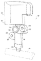
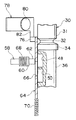
図1には、本発明の実施の形態に係る電動ステアリングロック装置10の構成が斜視図により示されている。
【0039】
電動ステアリングロック装置10は、車両のステアリングポスト(図示省略)に取り付けられるロックボディ12を備えている。ロックボディ12は金属により形成されており、箱状の本体部14と、この本体部14からステアリングシャフト16側へ向けて突設された筒状のガイド部18とを一体に有している。
【0040】
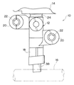
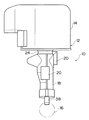
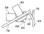
図2に示すように、ガイド部18の外周部には、ステアリングシャフトと平行な方向の両側にステアリングポスト取付け用の取付部20が突設されている。この取付部20に形成された取付孔22にボルト(図示省略)が挿入されてステアリングポストに締結されることで、ロックボディ12はステアリングポストに取り付けられる。
【0041】
また、本体部14とガイド部18との境界部分には、溝状の連結部24がガイド部18の軸線周りに形成されている。このロックボディ12に所定値以上の衝撃が加えられた際には、連結部24を起点としてロックボディ12が破断し、本体部14とガイド部18とに分断されるようになっている。
【0042】
また、本体部14内には、駆動源とされるモーター(図示省略)及び、このモーターにギア(図示省略)を介して駆動されるカム部(図示省略)等が収容されている。このモーターは、本体部14内に配設されている図示しない配線を介して電力を供給されて正・逆回転する。
【0043】
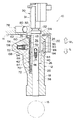
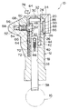
図4に示すように、ガイド部18の筒内は段付き状をなしており、円形断面形状の径大部26と矩形断面形状の径小部28とが形成されている。径大部26は本体部14内と連通しており、棒状のロックストッパ30が本体部14内と径大部26内とに跨った状態で、径大部26の内壁及び本体部14内に形成された摺動壁(図示省略)に沿って移動可能に配置されている。このロックストッパ30は、本体部14内に設けられた付勢手段とされるスプリング(図示省略)によりステアリングシャフト16側(図4の矢印L方向)へ付勢されると共に、本体部14内において前記カム部に係合しており、前記モーターにより駆動されるカム部の回動に対応して、矢印L方向及び矢印UL方向へ移動されるようになっている。
【0044】
また、このロックストッパ30の長手方向中間部の外周には、ロックボディ12の連結部24に対応する位置において、溝状の脆弱部32が軸線周りに形成されている。ロックボディ12が連結部24を起点として本体部14とガイド部18とに分断された際に、ロックストッパ30がこの脆弱部32を起点として破断し、本体部14側の基端部31とガイド部18側の先端部36とに分断されるようになっている。
【0045】
先端部36の脆弱部32側の端部には、外周に軸線周りに突出した鍔錠の遮蔽部34が形成されている。この遮蔽部34の外径は径大部26の内径よりも僅かに小径とされている。
【0046】
また、先端部36の遮蔽部34よりも先端側(図4では下側)は矩形断面形状に形成されており、ガイド部18の径小部28に沿って移動可能に設けられた角棒状のロックバー38の基端側に突設された一対の連結部40の間に挟まれている。この一対の連結部40は板状とされ略中央部には長孔42が形成されており、この長孔42内に、先端部36に突設された突起44が係合することで、ロックストッパ30とロックバー38とが連結されている。また、ロックストッパ30とロックバー38との間にはスプリング46が設けられており、ロックストッパ30とロックバー38とが互いに離れる方向に付勢している。
【0047】
ここで、前記モーターが正回転されると、前記モーターにより駆動されるカム部の回動により、ロックストッパ30がロックボディ12のガイド部18側(図4では矢印L方向)へ移動される。これにより、ロックストッパ30に連結されたロックバー38が矢印L方向へ移動してガイド部18の先端から突出し、ステアリングシャフト16に形成された係合溝(図示省略)に係合するようになっている。このロックバー38の係合によりステアリングシャフト16は回動不能にロックされる(図4図示状態)。
【0048】
そして、前記モーターが逆回転されると、前記モーターにより駆動されるカム部により、ロックストッパ30が、本体部14内に設けられたスプリングの付勢力に抗してロックボディ12の本体部14側(図5では矢印ULの方向)へ移動される。これにより、ロックストッパ30に連結されたロックバー38がステアリングシャフト16とは反対の方向(矢印UL方向)へ移動してステアリングシャフト16のロック状態が解除されるようになっている(図5図示状態)。
【0049】
また、ロックストッパ30の先端部36の側面(図4では左側の面)には、嵌入凹部とされる矩形断面形状の孔である嵌入孔48(図4では上側)と、第2の嵌入凹部とされる矩形断面形状の孔である嵌入孔50(図4では下側)とが、ロックストッパ30の長手方向に並んで設けられている。ロックストッパ30が前記カム部の回動に対応して、ロックボディ12のガイド部18側に移動した状態(図4図示状態)において、嵌入孔48と対向する径大部26の内壁には円形断面形状の孔である孔部52が設けられている。また、この孔部52の周りのガイド部18の外壁は孔部52に対応して突出している(図3参照)。
【0050】
孔部52は径大部54と径小部56とを有して段付き状をなしており、この孔部52内には、略円柱状のロックピン58が孔部52の内壁に沿って移動可能に挿入されている。図6に示すように、ロックピン58は長手方向中間部において、軸線周りに外周から突出した鍔状の鍔部60を有している。また、このロックピン58の鍔部60よりロックストッパ30側の部分の外径は、嵌入孔48及び嵌入孔50の孔幅よりも僅かに細く形成されており、嵌入孔48及び嵌入孔50に嵌入可能な嵌入部62とされる。
【0051】
そして、ロックストッパ30がロックボディ12の本体部14側へ移動された状態(図5図示状態)では、嵌入孔50がロックピン58の嵌入部62と対向する位置に配置され、ロックストッパ30がロックボディ12のガイド部18側へ移動された状態(図4図示状態)では、嵌入孔48がロックピン58の嵌入部62と対向する位置に配置されるようになっている。
【0052】
また、ロックピン58の鍔部60と孔部52の段付き部分との間には、付勢手段とされるスプリング68が設けられており、スプリング68によりピン58はロックストッパ30の側に付勢されている。
【0053】
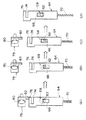
そして、このピン58とロックストッパ30との間には、略矩形状の薄板である可動プレート64が設けられており、ロックピン58の嵌入部62の先端が可動プレート64に当接して、ロックピン58のロックストッパ30側への移動が阻止されている。図8に示すように、この可動プレート64の中央部には、矩形の貫通孔66が形成されており、可動プレート64に当接したロックピン58の嵌入部62の先端が、貫通孔66の孔縁に引っ掛かった状態となっている。そして、貫通孔66の孔幅は、ロックピン58の嵌入部62の外径よりも大きく形成されており、嵌入部62が挿通可能とされている。
【0054】
また、可動プレート64の長手方向一端側(図4では下側)において、ガイド部18にはスプリング孔70が形成されており、このスプリング孔70内に付勢手段とされるスプリング72が挿入されている。このスプリング72により、可動プレート64は本体部14の方向に付勢されている。
【0055】
そして、図8に示すように、可動プレート64のスプリング72とは反対側の端部には溝部74が形成されており、可動プレート64の溝部74を挟んで本体部14側の短冊状とされた係合端縁部76は、付け根の部分で僅かに折り曲げられている(図6及び図7参照)。
【0056】
可動プレート64の本体部14側には、略L字状に形成された薄板である固定プレート78が設けられている。固定プレート78は、図4に示すように、本体部14にネジ80により固定されている。そして、ロックボディ12の連結部24に対応する位置において、この固定プレート78の一端から突設された突出部82の先端が、可動プレート64の係合端縁部76に僅かに引っ掛かることで、可動プレート64の固定プレート78側への移動が阻止されている。また、図7に示すように、固定プレート78は長手方向が可動プレート64の係合端縁部76と直交する方向で、本体部14に固定されている。
【0057】
また、図4に示すように、可動プレート64及びロックストッパ30の先端部36を挟んで、ロックピン58とは反対側のガイド部18には、円形断面形状の孔であるカバー孔84が形成されている。このカバー孔84は段付き状をなしており、径大部86と径小部88とが形成されている。この径大部86には、円盤状のカバー90が圧入されている。
【0058】
次に、本発明の実施の形態の作用について説明する。
【0059】
上記構成の電動ステアリングロック装置10では、ステアリングシャフト16がロックバー38によりロックされた状態(図1乃至図4図示状態)において、モーターに電流が供給されてモーターが逆回転するとカム部が回動される。このカム部の回動により、ロックストッパ30がロックボディ12の本体部14側(図4では矢印UL方向)へ移動され、ロックバー38によるステアリングシャフト16のロックが解除される。
【0060】
このロックが解除された状態では、車両走行時において、車両の急制動に伴い運転者の膝などがロックボディ12の本体部14に衝突して、本体部14に所定値以上の衝撃が作用すると、ロックボディ12は連結部24を起点として破断し、本体部14とガイド部18とに分断される。また、ロックストッパ30も脆弱部32を起点として破断し、基端部31と先端部36とに分断される(図10参照)。これにより、運転者の膝などがロックボディ12及びロックストッパ30から受ける衝撃が軽減される。
【0061】
ここで、本体部14とガイド部18との分断に伴い、本体部14にネジ80により固定されている固定プレート78も本体部14と共に除去される。このため、図8(A)に示すように、固定プレート78の突出部82の先端に係合端縁部76が係合することにより固定プレート78側への移動を阻止されていた可動プレート64が、スプリング70の付勢力により移動する(図8(B)乃至図8(D)参照)。このため、スプリング68によりロックストッパ30の側へ付勢されると共に、可動プレート64の中央部に形成された貫通孔66の孔縁に当接することで移動を阻止されていたロックピン58の嵌入部62が、可動プレート64の貫通孔66に挿通してロックストッパ30に形成された嵌入孔50に嵌入する(図10図示状態)。これにより、ロックストッパ30の先端部36及びロックバー38がステアリングシャフト16の方向へ移動することが阻止されるため、車両走行中にロックボディ12が破壊されても、ステアリングシャフト16がロックバー38によりロックされることが防止される。
【0062】
このように、車両走行時にロックボディ12が破損した場合には、ステアリングシャフト16のアンロック状態が維持され、車両走行時の安全性が向上する。
【0063】
一方、ステアリングシャフト16がアンロック状態にあるとき(図5図示状態)に、車両を駐車するためにモーターに電流が供給されてモーターが正回転するとカム部が回動される。このカム部の回動により、ロックストッパ30がロックボディ12のガイド部18側(図5では矢印L方向)へ移動され、ロックバー38がステアリングシャフト16の係合溝(図示省略)に係合してステアリングシャフト16がロックされる(図1乃至図4図示状態)。
【0064】
なお、ロックバー38がステアリングシャフト16に係合する際に、ロックバー38とステアリングシャフト16の係合溝との位置にズレがあり、ロックバー38の先端がステアリングシャフト16の外周に当たってロックバー38の移動が制限される場合がある。この場合には、ロックバー38とロックストッパ30との間に設けられたスプリング46が縮むことで、ロックストッパ30のガイド部18側への移動は制限されないようになっている。そして、運転者がステアリングを回転操作して係合溝とロックバー38との位置が一致すれば、スプリング46に付勢力によりロックバー38が係合溝に係合し、ステアリングシャフト16がロックされる。
【0065】
このロック状態では、不正行為によりロックボディ12が破壊され、本体部14に所定値以上の衝撃が作用するとロックボディ12は連結部24を起点として破断し、本体部14とガイド部18とに分断される。また、ロックストッパ30も脆弱部32を起点として破断し、基端部31と先端部36とに分断される(図9参照)。
【0066】
ここで、この本体部14とガイド部18との分断に伴い、本体部14にネジ80により固定されている固定プレート78も本体部14と共に除去される。このため、図8(A)に示すように、固定プレート78の突出部82の先端に係合端縁部76が係合することにより固定プレート78側への移動を阻止されていた可動プレート64が、スプリング70の付勢力により移動する(図8(B)乃至図8(D)参照)。このため、スプリング68によりロックストッパ30の側へ付勢されると共に、可動プレート64の中央部に形成された貫通孔66の孔縁に当接することで移動を阻止されていたロックピン58の嵌入部62が、可動プレート64の貫通孔66に挿通してロックストッパ30の先端部36に形成された嵌入孔48に嵌入する(図9図示状態)。これにより、先端部36のガイド部18基端側(図9では上側)への移動が阻止されるため、先端部36及びロックバー30がガイド部18から引き抜かれて、ステアリングシャフト16のロックが解除されることが防止される。
【0067】
しかも、ロックストッパ30の嵌入孔48に嵌入したロックピン58はガイド部18の内部にあるため、ガイド部18を外側から観察しても、ロックストッパ30の移動を阻止しているロックピン58の機構や位置が分かりにくい。
【0068】
そして、この状態では、ガイド部18の径大部26の内壁とロックストッパ30との間の隙間が、可動プレート64及びロックストッパ30の遮蔽部34により塞がれている。そして、ロックピン58の嵌入部62が可動プレート64の貫通孔66に挿通した状態で、ロックストッパ30の嵌入孔48に嵌入するため、可動プレート64がガイド部18から引き抜かれることも防止される。これにより、ガイド部18の径大部26とロックストッパ30との間の隙間に、工具等がこじ入れられてロックピン58が破壊され、ロックピン58のロックストッパに対する係合を解除されることが防止される。
【0069】
さらに且つ、図6及び図7に示す如く、可動プレート64は、係合端縁部76の先端が固定プレート78の突出部82の先端に僅かに係合することで移動を阻止されており、可動プレート64と固定プレート78との係合が外れ易い構成とされている。また、この可動プレート64と固定プレート78とは、ロックボディ12の連結部24に対応する位置において係合している。
【0070】
このため、ロックボディ12に衝撃が加えられてロックボディ12の本体部14とガイド部18との間に僅かな亀裂が生じただけでも、可動プレート64と固定プレート78との係合が外れ、ロックピン58がロックストッパ30の嵌入孔48もしくは嵌入孔50に嵌入する。すなわち、本体部14とガイド部18とが完全に分断されない状態でも、ロックストッパ30及びロックバー38の移動が確実に阻止される。したがって、ロックボディ12を破壊することによりステアリングシャフト16のロック状態を解除することは極めて難しく盗難防止性が高い。また、車両走行時に万一ロックボディ12が破損して本体部14とガイド部18との間に亀裂が生じた場合にも、ステアリングシャフト16がロックされることがないので安全性が高い。
【0071】
このように、上記構成の電動ステアリングロック装置10では、車両駐車中にロックボディ12が破壊された場合には、ステアリングシャフト16のロック状態を維持し、しかも、不正行為によるロック状態の解除が困難で盗難防止性が高い。
【0072】
なお、上記実施の形態においては、ロックストッパ30とロックバー38とを別体として互いに連結する構成としたが、これに限らず、ロックストッパ30とロックバー38とは一体に形成されたものでもよい。この場合には、部品点数を低減することができ簡素化を図ることができる。
【0073】
また、上記実施の形態においては、ロックストッパ30に嵌入凹部とされる嵌入孔48と第2の嵌入凹部とされる嵌入孔50とを設ける構成としたが、これに限らず、ロックバー38に嵌入凹部と第2の嵌入凹部とを設け、この嵌入凹部と第2の嵌入凹部とに対応してロックピン58を配設する構成としてもよい。
【0074】
そして、上記実施の形態においては、連結部24が本体部14とガイド部18との境界部分に形成される構成としたが、これに限らず、連結部は、ロックストッパ30若しくはロックバー38に設けられた嵌入凹部、およびガイド部に配設されたロックピンよりも本体部14側(ステアリングシャフト16とは反対側)のロックボディ12に形成されればよい。
【0075】
さらに、上記実施の形態においては、嵌入凹部とされる嵌入孔48および、第2の嵌入凹部とされる嵌入孔50を矩形断面形状の孔としたが、嵌入凹部および第2の嵌入凹部は、ロックピン58が嵌入することでロックストッパ30の移動を阻止できるもの(例えば、溝など)であれば構わない。
【0076】
またさらに、上記実施の形態においては、駆動源としてモーターを使用し、このモーターによりカム部を駆動してロックストッパ30を移動させる構成としたが、モーターによりネジを駆動して、このネジ機構によりロックストッパ30を移動させる構成や、ソレノイド等により直接ロックストッパ30を移動させる構成とすることも可能である。
【0077】
【発明の効果】
以上説明したように、本発明の電動ステアリングロック装置によれば、車両駐車中にロックボディが破壊された場合には、ステアリングシャフトのロック状態を維持し、しかも、不正行為によるロック状態の解除が困難で盗難防止性が高い。
【図面の簡単な説明】
【図1】本発明の実施の形態に係る電動ステアリングロック装置の全体構成を示す斜視図である。
【図2】本発明の実施の形態に係る電動ステアリングロック装置の全体構成を示す背面図である。
【図3】本発明の実施の形態に係る電動ステアリングロック装置の全体構成を示す側面図である。
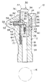
【図4】本発明の実施の形態に係る電動ステアリングロック装置の主要部の構成を示し、ステアリングシャフトがロックされた状態における部分断面図である。
【図5】本発明の実施の形態に係る電動ステアリングロック装置の主要部の構成を示し、ステアリングシャフトのロックが解除された状態における部分断面図である。
【図6】本発明の実施の形態に係る電動ステアリングロック装置の主要部の構成を示す部分断面図である。
【図7】本発明の実施の形態に係る電動ステアリングロック装置の構成部材とされるロックプレート及びロックピンの構成を示す上面図である。
【図8】本発明の実施の形態に係る電動ステアリングロック装置の構成部材とされるロックプレート及びロックピンの作動の過程を示し、(A)はロックボディ破壊前の状態を示す正面図であり、(B)はロックボディが破壊され本体部とガイド部とが分断された瞬間の状態を示す正面図であり、(C)はロックプレートの移動状態を示す正面図であり、(D)はロックプレートの貫通孔にロックピンが挿通した状態を示す正面図である。
【図9】本発明の実施の形態に係る電動ステアリングロック装置の主要部の構成を示し、車両駐車時にロックボディが破壊された状態おける部分断面図である。
【図10】本発明の実施の形態に係る電動ステアリングロック装置の主要部の構成を示し、車両走行時にロックボディが破壊された状態における部分断面図である。
【符号の説明】
10 電動ステアリングロック装置
12 ロックボディ
14 本体部
16 ステアリングシャフト
18 ガイド部
24 連結部
30 ロックストッパ
32 脆弱部
38 ロックバー
48 嵌入孔(嵌入凹部)
50 嵌入孔(第2の嵌入凹部)
58 ロックピン
64 移動プレート(ロックプレート)
66 貫通孔
68 スプリング(付勢手段)
70 スプリング(付勢手段)
78 固定プレート(ロックプレート)[0001]
TECHNICAL FIELD OF THE INVENTION
The present invention relates to an electric steering lock device applied to a vehicle such as an automobile.
[0002]
[Prior art]
Vehicles such as automobiles include, for example, a so-called electric steering lock device as an anti-theft device. The electric steering lock device includes, for example, a lock body that is assembled to a steering post of a vehicle. The lock body integrally has a main body for accommodating the driving means and a cylindrical guide protruding from the main body toward the steering shaft. Inside the main body, a cam unit is connected to a motor serving as a driving unit, and the cam unit rotates in accordance with forward / reverse rotation of the motor. A lock stopper movably corresponding to the rotation of the cam part and urged toward the steering shaft by a spring, and a lock bar having one end engaged with the lock stopper are provided in the guide part cylinder. And are arranged.
[0003]
In the electric steering lock device having the above configuration, the tip of the lock bar projects toward the steering shaft to lock the steering shaft so that it cannot rotate, and the cam portion locks the lock stopper and the lock bar against the urging force of the spring. The lock bar is disengaged from the steering shaft by being moved in a direction opposite to the shaft.
[0004]
On the other hand, some general steering lock devices operated by keys have basically the same configuration as the above-mentioned electric steering lock device. In such a steering lock device, a key cylinder into which a key is inserted is housed in a main body portion, and a cam portion of a cam shaft is rotated by a rotation operation of a key inserted into the key cylinder. I have. Then, the lock stopper and the lock bar move in the cylinder of the guide portion in accordance with the rotation of the cam portion.
[0005]
By the way, when the vehicle suddenly decelerates, the driver's knee may strongly hit the main body or the guide of the lock body and receive a large impact. Therefore, when the main body or the guide portion of the lock body receives an impact force equal to or more than a predetermined value, the intermediate portion of the guide portion is damaged, so that a steering lock device configured to reduce the impact received by the driver is provided. Has been proposed by the present applicant (see Patent Document 1).
[0006]
Further, in the steering lock device disclosed in Patent Document 1, the lock bar is disengaged from the lock bar and the lock bar becomes movable due to the breakage of the guide portion of the lock body. Blocking means for preventing the steering shaft from being locked. That is, an engaging member which is urged to the lock bar side and whose movement is normally restricted is provided at the distal end side of the guide portion, and the restriction is released and the engagement is released when the intermediate portion of the guide portion is damaged. By moving the member and engaging the engaging portion provided on the lock bar, the movement of the lock bar is restricted.
[0007]
In addition, according to this configuration, even when the lock body is destroyed by improper action during parking of the vehicle, the movement of the lock bar can be restricted by the engagement member, and the lock state of the steering shaft by the lock bar can be prevented. (So-called “deadlock mechanism”).
[0008]
However, in the steering lock device disclosed in Patent Document 1, the engaging member and the regulating member that regulates the movement of the engaging member are exposed outside the lock body. Fixing the engaging member may prevent the engaging member from being engaged with the lock bar.
[0009]
Therefore, a steering lock device in which the engagement member and the regulating member are installed inside the lock body to improve the anti-theft property has been proposed by the present applicant (see Patent Document 2).
[0010]
In the steering lock device disclosed in Patent Document 2, the camshaft is provided in the guide portion, and when the lock body is broken, the main body portion and the guide portion are separated. . The movement of the engaging member is regulated by a regulating member disposed between the guide portion and the camshaft and having one end fixed to the main body portion. For this reason, since the regulating member is removed along with the separation between the main body and the guide portion, the engaging member moves to the camshaft side and engages with the engaging hole provided in the camshaft. Thereby, the movement of the cam shaft, the lock stopper, and the lock bar is restricted.
[0011]
However, in the steering lock device of Patent Literature 2, since the restricting member is removed together with the main body along with the separation of the main body and the guide, a gap is generated between the guide and the camshaft. . Therefore, there is a possibility that the position of the engaging member is specified from the gap, and the engaging member engaged with the camshaft is detached by some method, and a measure for preventing this is required.
[0012]
[Patent Document 1]
JP-A-7-9944
[Patent Document 2]
JP 2000-225922 A
[0013]
[Problems to be solved by the invention]
In consideration of the above facts, the present invention maintains the locked state of the steering shaft when the lock body is destroyed during parking of the vehicle, and furthermore, it is difficult to release the locked state due to fraud and the anti-theft property is improved. The aim is to obtain a high electric steering lock device.
[0014]
[Means for Solving the Problems]
In order to achieve the above object, an electric steering lock device according to the present invention has a main body in which a driving source is housed, and a cylinder protruding from the main body toward a steering shaft of a vehicle. A lock body having a shape of a guide portion, a connecting portion capable of separating the lock body when an impact greater than or equal to a predetermined value acts on the lock body, and a lock stopper that moves by a driving force from the drive source. A base end portion is connected to the lock stopper and is provided in the guide portion so as to be movable integrally with the lock stopper. When the lock stopper is moved to the guide portion side of the lock body, the distal end portion is the guide member. Protruding from the tip of the portion toward the steering shaft to lock the steering shaft, and the lock stopper A lock bar for releasing the lock of the steering shaft by moving the distal end in a direction opposite to the steering shaft when the lock body is moved to the main body side of the lock body, and a guide hole; A lock stopper is provided movably in the direction of the main body, and is urged by the urging means toward the main body. Normally, the main body comes into contact with the main body to move toward the main body. The blocked lock plate is provided on the guide portion so as to be movable in a direction intersecting the moving direction of the lock stopper. A lock pin that is prevented from moving toward the lock stopper by contacting a hole edge; And a fitting recess formed in the lock stopper at a position facing the lock pin with the lock plate interposed therebetween, and the lock pin being able to be fitted therein. .
[0015]
In the electric steering lock device according to the first aspect, when the vehicle is parked, the lock stopper is moved to the guide portion side of the lock body, so that the distal end portion of the lock bar projects from the distal end of the guide portion to lock the steering shaft. I have.
[0016]
In this locked state, when the lock body is destroyed by improper action and an impact greater than or equal to a predetermined value acts on the lock body, the lock body is separated from the connecting portion as a starting point. For this reason, the lock plate, which has been prevented from moving toward the main body by the main body, moves by the urging force of the urging means. Then, the lock pin, which has been urged by the urging means toward the lock stopper side and prevented from moving by being in contact with the hole edge of the through hole formed in the lock plate, is inserted into the through hole of the lock plate. It fits into a fitting recess formed in the lock stopper. Accordingly, the movement of the lock stopper is prevented, so that the movement of the lock bar whose base end is connected to the lock stopper is also restricted. Therefore, even if the lock body is destroyed due to cheating while the vehicle is parked, the lock of the steering shaft is prevented from being released.
[0017]
In addition, since the lock pin is inserted into the insertion recess of the lock stopper with the lock pin inserted through the through hole of the lock plate, the movement of the lock plate with respect to the guide portion is restricted, and the lock plate is prevented from being pulled out of the guide portion. . As a result, since the space between the guide portion and the lock stopper is closed by the lock plate, it becomes difficult to break the lock pin from between the guide portion and the lock stopper and unlock the steering shaft. The anti-theft property is improved.
[0018]
As described above, in the electric steering lock device according to the first aspect, when the lock body is broken while the vehicle is parked, the locked state of the steering shaft is maintained, and it is difficult to release the locked state due to fraud. High anti-theft properties.
[0019]
An electric steering lock device according to a second aspect of the present invention is the electric steering lock device according to the first aspect, wherein the lock plate and the urging means for urging the lock plate, and the lock pin and the lock pin are provided. The urging means for urging is provided so as not to be exposed inside the guide portion.
[0020]
In the electric steering lock device according to the second aspect of the present invention, the lock pin, the lock plate, and the urging means for urging the lock pin and the lock plate are provided so as not to be exposed inside the guide portion. For this reason, it is difficult to grasp the mechanism and position of the lock plate and the lock pin from the appearance.
[0021]
Also, when the lock body is divided by a shock such as a burglar or the like that is applied to the lock body by a predetermined amount or more, the gap between the guide portion and the lock stopper is blocked by the lock plate, and the inside of the guide portion is blocked. Since it is not exposed, it is difficult to grasp the mechanism and position of the lock pin.
[0022]
On the other hand, even if the position of the lock pin is specified, if the guide portion (generally made of metal) is destroyed and the lock pin is not removed from the fitting recess of the lock stopper, the lock state of the steering shaft by the lock bar can be released. Can not. Therefore, it takes a considerable time to release the locked state, and the anti-theft property is further improved.
[0023]
Thus, in the electric steering lock device according to the second aspect, the anti-theft property when the vehicle is parked is further improved.
[0024]
An electric steering lock device according to a third aspect of the present invention is the electric steering lock device according to the first or second aspect, wherein the lock stopper is moved toward the main body of the lock body. A stopper is formed at a position facing the lock pin with the lock plate interposed therebetween, and has a second fitting concave portion into which the lock pin can be fitted.
[0025]
In the electric steering lock device according to the third aspect, when the vehicle is running, the lock stopper is moved toward the main body of the lock body, so that the distal end of the lock bar moves in the direction opposite to the steering shaft, and the steering shaft is moved. The lock has been released.
[0026]
In the unlocked state, when the occupant's knee or the like collides with the lock body due to sudden braking of the vehicle, and an impact of a predetermined value or more acts on the lock body, the lock body starts from the connecting portion. Be divided. As a result, the impact that the occupant's knees receive from the lock body is reduced.
[0027]
Further, at this time, the lock plate, which has been prevented from moving toward the main body by the main body, moves by the urging force of the urging means. Then, the lock pin, which has been urged by the urging means toward the lock stopper side and prevented from moving by being in contact with the hole edge of the through hole formed in the lock plate, is inserted into the through hole of the lock plate. It is fitted into a second fitting recess formed in the lock stopper. Accordingly, the movement of the lock stopper is prevented, so that the movement of the lock bar whose base end is connected to the lock stopper is also restricted. Therefore, even if the lock body is broken during running of the vehicle, the steering shaft is prevented from being locked by the lock bar.
[0028]
As described above, in the electric steering lock device according to the third aspect, when the lock body is broken during traveling of the vehicle, the unlocked state of the steering shaft is maintained, and safety during traveling of the vehicle is improved.
[0029]
An electric steering lock device according to a fourth aspect of the present invention is the electric steering lock device according to any one of the first to third aspects, wherein the electric steering lock device is provided at a position corresponding to the connecting portion of the lock stopper. The lock body is characterized in that it has a fragile portion that can divide the lock stopper itself at the time of the severing of the lock body.
[0030]
In the electric steering lock device according to the fourth aspect, when an impact of a predetermined value or more acts on the lock body and the lock body is separated from the connection portion as a starting point, the lock stopper itself is positioned at a position corresponding to the connection portion. Is divided from the fragile part provided in
[0031]
As a result, the lock body is destroyed due to misconduct, and it is difficult to pinch the lock stopper in a state where the lock pin is prevented from moving by the lock pin. Therefore, the lock stopper is forcibly pulled out to release the lock. Can be prevented.
[0032]
Further, when the occupant's knee or the like collides with the lock body during running of the vehicle, the occupant's knee or the like is prevented from receiving an impact from the lock stopper, and the occupant's safety is further improved.
[0033]
Thus, in the electric steering lock device according to the fourth aspect, the anti-theft system when the vehicle is parked and the safety when the vehicle is traveling are further improved.
[0034]
An electric steering lock device according to a fifth aspect of the present invention is the electric steering lock device according to any one of the first to fourth aspects, wherein the lock plate includes a fixing plate fixed to the main body. A movable portion which is provided between the inner wall of the guide portion and the lock stopper so as to be movable in the direction of the fixed plate, and is urged toward the fixed plate by the urging means. And at the position corresponding to the connecting portion of the lock body, the edge of the movable plate is engaged with the edge of the fixed plate at the position corresponding to the connecting portion of the lock body, so that the movable plate is closer to the fixed plate. Is prevented from moving.
[0035]
In the electric steering lock device according to the fifth aspect, the edge of the fixed plate fixed to the main body is engaged with the edge of the movable plate provided on the guide portion, so that the movable plate is moved toward the fixed plate. Movement is prevented, and the movable plate and the fixed plate are easily disengaged from each other. The fixed plate and the movable plate are engaged at a position corresponding to the connecting portion of the lock body.
[0036]
Therefore, even if a shock is applied to the lock body and a slight crack is generated in the connecting portion, the fixed plate and the movable plate are disengaged from each other, the movable plate moves, the lock pin also moves, and the lock stopper moves. Prevent movement. That is, even when the main body and the guide are not completely separated from each other, the movement of the lock stopper and the lock bar is reliably prevented, so that theft prevention during parking of the vehicle and the safety during traveling of the vehicle are further improved.
[0037]
Thus, in the electric steering lock device according to the fifth aspect, the anti-theft property when the vehicle is parked and the safety when the vehicle is running are further improved.
[0038]
BEST MODE FOR CARRYING OUT THE INVENTION
FIG. 1 is a perspective view showing a configuration of an electric
[0039]
The electric
[0040]
As shown in FIG. 2, mounting
[0041]
A groove-shaped connecting
[0042]
Further, a motor (not shown) serving as a driving source and a cam unit (not shown) driven by a gear (not shown) are accommodated in the
[0043]
As shown in FIG. 4, the inside of the cylinder of the
[0044]
A groove-shaped
[0045]
At the end of the
[0046]
Further, the distal end side of the distal end portion 36 (the lower side in FIG. 4) with respect to the shielding
[0047]
Here, when the motor is rotated forward, the rotation of the cam portion driven by the motor moves the
[0048]
When the motor is rotated in the reverse direction, the cam portion driven by the motor causes the
[0049]
Further, a fitting hole 48 (upper side in FIG. 4), which is a hole having a rectangular cross-sectional shape that is a fitting recess, is provided on a side surface (a left surface in FIG. 4) of the
[0050]
The
[0051]
When the
[0052]
A
[0053]
A
[0054]
A
[0055]
As shown in FIG. 8, a
[0056]
On the side of the
[0057]
As shown in FIG. 4, a
[0058]
Next, the operation of the embodiment of the present invention will be described.
[0059]
In the electric
[0060]
In the unlocked state, if the driver's knee or the like collides with the
[0061]
Here, the fixing
[0062]
As described above, when the
[0063]
On the other hand, when the steering
[0064]
When the
[0065]
In this locked state, the
[0066]
Here, as the
[0067]
Moreover, since the
[0068]
In this state, the gap between the inner wall of the large-
[0069]
Further, as shown in FIGS. 6 and 7, the
[0070]
Therefore, even if a slight crack is generated between the
[0071]
As described above, in the electric
[0072]
In the above-described embodiment, the
[0073]
Further, in the above embodiment, the
[0074]
In the above-described embodiment, the connecting
[0075]
Further, in the above-described embodiment, the
[0076]
Furthermore, in the above embodiment, a motor is used as a drive source, and the cam is driven by the motor to move the
[0077]
【The invention's effect】
As described above, according to the electric steering lock device of the present invention, when the lock body is broken while the vehicle is parked, the locked state of the steering shaft is maintained, and the locked state can be released by wrongdoing. Difficult and has high anti-theft properties.
[Brief description of the drawings]
FIG. 1 is a perspective view showing an overall configuration of an electric steering lock device according to an embodiment of the present invention.
FIG. 2 is a rear view showing the entire configuration of the electric steering lock device according to the embodiment of the present invention.
FIG. 3 is a side view showing the overall configuration of the electric steering lock device according to the embodiment of the present invention.
FIG. 4 is a partial cross-sectional view showing a configuration of a main part of the electric steering lock device according to the embodiment of the present invention, in a state where a steering shaft is locked.
FIG. 5 is a partial cross-sectional view illustrating a configuration of a main part of the electric steering lock device according to the embodiment of the present invention, in a state where the lock of the steering shaft is released.
FIG. 6 is a partial cross-sectional view showing a configuration of a main part of the electric steering lock device according to the embodiment of the present invention.
FIG. 7 is a top view showing a configuration of a lock plate and a lock pin which are constituent members of the electric steering lock device according to the embodiment of the present invention.
FIG. 8 is a front view showing a process of operating a lock plate and a lock pin which are constituent members of the electric steering lock device according to the embodiment of the present invention, and FIG. 8 (A) is a front view showing a state before a lock body is broken. (B) is a front view showing a state at the moment when the lock body is broken and the main body and the guide part are separated, (C) is a front view showing a moving state of the lock plate, and (D) is a front view. It is a front view showing the state where the lock pin was inserted in the through-hole of the lock plate.
FIG. 9 is a partial cross-sectional view showing a configuration of a main part of the electric steering lock device according to the embodiment of the present invention, in a state where a lock body is broken when the vehicle is parked.
FIG. 10 is a partial cross-sectional view showing a configuration of a main part of the electric steering lock device according to the embodiment of the present invention, in a state where a lock body is broken during traveling of the vehicle.
[Explanation of symbols]
10 Electric steering lock device
12 Lock body
14 Body
16 Steering shaft
18 Guide part
24 Connecting part
30 Lock stopper
32 Vulnerable part
38 Rock Bar
48 Fitting hole (fitting recess)
50 fitting hole (second fitting recess)
58 Lock Pin
64 Moving plate (lock plate)
66 Through hole
68 spring (biasing means)
70 spring (biasing means)
78 Fixing plate (lock plate)
Claims (5)
前記ロックボディに所定値以上の衝撃が作用した際に前記ロックボディを分断可能とする連結部と、
前記駆動源からの駆動力によって移動するロックストッパと、
基端部が前記ロックストッパに連結されると共に前記ガイド部内に前記ロックストッパと一体に移動可能に設けられ、前記ロックストッパが前記ロックボディのガイド部側へ移動された状態では先端部が前記ガイド部の先端から前記ステアリングシャフトの方向へ突出して前記ステアリングシャフトをロックし、前記ロックストッパが前記ロックボディの本体部側へ移動された状態では前記先端部が前記ステアリングシャフトとは反対方向へ移動して前記ステアリングシャフトの前記ロックを解除するロックバーと、
貫通孔を有し、前記ガイド部と前記ロックストッパとの間に前記本体部の方向へ移動可能に設けられると共に付勢手段により前記本体部側へ付勢され、通常時は前記本体部に当接することにより前記本体部側への移動を阻止されたロックプレートと、
前記ガイド部に前記ロックストッパの移動方向と交差する方向へ移動可能に設けられ、付勢手段により前記ロックストッパ側へ付勢されると共に前記ロックプレートの前記貫通孔の孔縁に当接することにより前記ロックストッパ側への移動を阻止されたロックピンと、
前記ロックストッパが前記ロックボディのガイド部側へ移動された状態で、前記ロックストッパの前記ロックプレートを挟んで前記ロックピンと対向する位置に形成され、前記ロックピンが嵌入可能とされた嵌入凹部と、
を備えた電動ステアリングロック装置。A lock body having a main body in which a drive source is housed, and having a cylindrical guide protruding from the main body toward the steering shaft of the vehicle;
A connecting portion that allows the lock body to be separated when an impact greater than or equal to a predetermined value acts on the lock body;
A lock stopper that moves by a driving force from the driving source,
A base end portion is connected to the lock stopper and is provided in the guide portion so as to be movable integrally with the lock stopper. When the lock stopper is moved to the guide portion side of the lock body, the distal end portion is the guide. When the lock stopper is moved toward the main body of the lock body, the tip moves in the direction opposite to the steering shaft when the lock stopper is moved toward the body of the lock body. A lock bar for unlocking the steering shaft.
A through hole is provided between the guide portion and the lock stopper so as to be movable in the direction of the main body, and is urged toward the main body by an urging means. A lock plate that is prevented from moving toward the main body by contacting the lock plate;
The guide portion is provided so as to be movable in a direction intersecting with the movement direction of the lock stopper, and is urged toward the lock stopper by an urging means, and abuts on a hole edge of the through hole of the lock plate. A lock pin that is prevented from moving to the lock stopper side,
In a state where the lock stopper is moved to the guide portion side of the lock body, the lock stopper is formed at a position facing the lock pin with the lock plate interposed therebetween, and a fitting recess in which the lock pin can be fitted. ,
Electric steering lock device equipped with.
ことを特徴とする請求項1記載の電動ステアリングロック装置。The lock plate and the urging means for urging the lock plate, and the lock pin and the urging means for urging the lock pin are provided so as not to be exposed inside the guide portion.
The electric steering lock device according to claim 1, wherein:
ことを特徴とする請求項1記載または請求項2記載の電動ステアリングロック装置。In a state where the lock stopper is moved to the main body side of the lock body, a second position is formed at a position facing the lock pin with the lock plate interposed therebetween, and the lock pin can be fitted therein. Having a fitting recess,
The electric steering lock device according to claim 1 or 2, wherein:
ことを特徴とする請求項1乃至請求項3の何れか一項に記載の電動ステアリングロック装置。A fragile portion that is provided at a position corresponding to the connecting portion of the lock stopper and that can sever the lock stopper itself at the time of the severing of the lock body;
The electric steering lock device according to any one of claims 1 to 3, wherein:
前記ロックボディの前記連結部に対応する位置において、前記固定プレートの端縁に前記可動プレートの端縁が係合することで前記可動プレートの前記固定プレート側への移動が阻止される、
ことを特徴とする請求項1乃至請求項4の何れか一項に記載の電動ステアリングロック装置。The lock plate is provided between the inner wall of the guide portion and the lock stopper so as to be movable in the direction of the fixed plate. And a movable plate biased toward the fixed plate by the biasing means.
At a position corresponding to the connecting portion of the lock body, the edge of the movable plate is engaged with the edge of the fixed plate, so that the movable plate is prevented from moving toward the fixed plate.
The electric steering lock device according to any one of claims 1 to 4, wherein:
Priority Applications (2)
| Application Number | Priority Date | Filing Date | Title |
|---|---|---|---|
| JP2003024681A JP4038132B2 (en) | 2003-01-31 | 2003-01-31 | Electric steering lock device |
| US10/760,413 US7055351B2 (en) | 2003-01-31 | 2004-01-21 | Electrically-driven steering lock device |
Applications Claiming Priority (1)
| Application Number | Priority Date | Filing Date | Title |
|---|---|---|---|
| JP2003024681A JP4038132B2 (en) | 2003-01-31 | 2003-01-31 | Electric steering lock device |
Publications (2)
| Publication Number | Publication Date |
|---|---|
| JP2004231122A true JP2004231122A (en) | 2004-08-19 |
| JP4038132B2 JP4038132B2 (en) | 2008-01-23 |
Family
ID=32767594
Family Applications (1)
| Application Number | Title | Priority Date | Filing Date |
|---|---|---|---|
| JP2003024681A Expired - Fee Related JP4038132B2 (en) | 2003-01-31 | 2003-01-31 | Electric steering lock device |
Country Status (2)
| Country | Link |
|---|---|
| US (1) | US7055351B2 (en) |
| JP (1) | JP4038132B2 (en) |
Cited By (16)
| Publication number | Priority date | Publication date | Assignee | Title |
|---|---|---|---|---|
| JP2007153171A (en) * | 2005-12-06 | 2007-06-21 | Tokai Rika Co Ltd | Fixing structure of electric steering lock device |
| JP2007153172A (en) * | 2005-12-06 | 2007-06-21 | Tokai Rika Co Ltd | Electric steering lock device |
| JP2007269176A (en) * | 2006-03-31 | 2007-10-18 | Alpha Corp | Steering lock device |
| WO2008050664A1 (en) * | 2006-10-26 | 2008-05-02 | Alpha Corporation | Electric steering lock device |
| WO2008056727A1 (en) * | 2006-11-10 | 2008-05-15 | Alpha Corporation | Electric steering lock device |
| WO2008056728A1 (en) * | 2006-11-10 | 2008-05-15 | Alpha Corporation | Steering lock device |
| WO2008123073A1 (en) | 2007-03-29 | 2008-10-16 | Alpha Corporation | Steering lock device |
| JP2008247129A (en) * | 2007-03-29 | 2008-10-16 | Alpha Corp | Steering lock device |
| JP2009046096A (en) * | 2007-08-23 | 2009-03-05 | Yuhshin Co Ltd | Steering locking device |
| JP2009083642A (en) * | 2007-09-28 | 2009-04-23 | Alpha Corp | Steering lock device |
| JP2012506338A (en) * | 2008-10-23 | 2012-03-15 | ヴァレオ セキュリテ アビタクル | Anti-theft device for automobile steering |
| US8474291B2 (en) | 2007-07-20 | 2013-07-02 | Huf Hulsbeck & Furst Gmbh Co. Kg | Locking device with arresting part |
| WO2015049952A1 (en) | 2013-10-03 | 2015-04-09 | 株式会社 アルファ | Steering lock device |
| WO2015174489A1 (en) * | 2014-05-16 | 2015-11-19 | 株式会社 アルファ | Steering lock device |
| WO2015182598A1 (en) * | 2014-05-27 | 2015-12-03 | 株式会社 アルファ | Steering lock device |
| JP2020519524A (en) * | 2017-05-11 | 2020-07-02 | マルクアルト ゲーエムベーハーMarquardt Gesellschaft Mit Beschrankter Haftung | Locking devices, especially locking devices for motor vehicles |
Families Citing this family (27)
| Publication number | Priority date | Publication date | Assignee | Title |
|---|---|---|---|---|
| EP1506107A4 (en) * | 2002-05-23 | 2008-11-12 | Methode Electronics Inc | Steering lock device |
| DE10247803B3 (en) * | 2002-10-14 | 2004-01-29 | Huf Hülsbeck & Fürst Gmbh & Co. Kg | Device for locking the steering spindle of a motor vehicle |
| FR2871759B1 (en) * | 2004-06-17 | 2007-10-19 | Valeo Securite Habitacle Sas | ANTI-THEFT ANTI-THEFT DEVICE WITH INSERABLE LOCK, IN PARTICULAR FOR A MOTOR VEHICLE |
| US7730752B2 (en) * | 2006-03-13 | 2010-06-08 | Kawasaki Jukogyo Kabushiki Kaisha | Theft prevention apparatus for leisure vehicle |
| EP1953048A1 (en) * | 2007-02-02 | 2008-08-06 | Valeo Sicherheitssysteme GmbH | Device for locking the steering shaft of a vehicle |
| US7891221B2 (en) * | 2007-10-01 | 2011-02-22 | Alpha Corporation | Electric steering lock device |
| US7596976B2 (en) * | 2007-11-30 | 2009-10-06 | Alpha Corporation | Electric steering lock device |
| ITTO20090105A1 (en) * | 2009-02-13 | 2010-08-14 | Trw Automotive Italia S P A | ELECTRIC STEERING LOCK FOR VEHICLES |
| DE102009034606B4 (en) * | 2009-07-24 | 2019-08-29 | Huf Hülsbeck & Fürst Gmbh & Co. Kg | Device for locking a functionally essential component of a motor vehicle |
| JP4952751B2 (en) * | 2009-07-24 | 2012-06-13 | アイシン精機株式会社 | Vehicle door lock device |
| DE102009045905A1 (en) * | 2009-10-21 | 2011-04-28 | Huf Hülsbeck & Fürst Gmbh & Co. Kg | Device for relocating a displaceable locking unit |
| FR2952005B1 (en) * | 2009-11-05 | 2016-03-25 | Valeo Securite Habitacle | ANTI-THEFT DEVICE FOR THE STEERING COLUMN OF A SUPER-CONDEMNATION VEHICLE ASSURED BY ROCKER |
| FR2952332B1 (en) * | 2009-11-06 | 2013-11-29 | Valeo Securite Habitacle | ANTI-THEFT DEVICE FOR THE STEERING COLUMN OF A VEHICLE WITH HIGH CONDAMNATION ENSURED BY INTERMEDIATE ROCKET |
| US8424348B2 (en) * | 2010-01-27 | 2013-04-23 | Strattec Security Corporation | Steering lock |
| DE102010037071A1 (en) * | 2010-08-19 | 2012-02-23 | Huf Hülsbeck & Fürst Gmbh & Co. Kg | Device for displacing a movable blocking element |
| US9422753B2 (en) * | 2010-12-17 | 2016-08-23 | Kabushiki Kaisha Honda Lock | Vehicular electric lock device |
| ES2457241T3 (en) * | 2011-01-21 | 2014-04-25 | Valeo Sicherheitssysteme Gmbh | Steering theft for motor vehicle |
| JP5352654B2 (en) * | 2011-03-30 | 2013-11-27 | アイシン精機株式会社 | Vehicle door lock device |
| FR2978403A1 (en) * | 2011-07-25 | 2013-02-01 | Valeo Securite Habitacle | ANTI-THEFT DEVICE FOR STEERING COLUMN AND STEERING COLUMN THEREFOR |
| US8534719B2 (en) | 2011-09-09 | 2013-09-17 | Adams Rite Manufacturing Co. | Door top latching actuation |
| FR2984822B1 (en) * | 2011-12-21 | 2014-04-11 | Valeo Securite Habitacle | STEERING ANTI-THEFT FOR MOTOR VEHICLE WITH SUPERCONDAMNATION AND ASSOCIATED MOUNTING METHOD |
| CN102628328A (en) * | 2012-05-08 | 2012-08-08 | 天合汽车零部件(苏州)有限公司 | Mechanical tubular column ignition lock |
| DE102013217735A1 (en) | 2012-09-07 | 2014-03-13 | Strattec Security Corporation | steering lock |
| US8966948B2 (en) * | 2012-12-03 | 2015-03-03 | Hyundai Motor Company | Electrical steering column lock |
| JP6290043B2 (en) * | 2014-08-28 | 2018-03-07 | トヨタ紡織株式会社 | Gearbox mounting structure with motor for power seat for vehicles |
| DE102014112816A1 (en) | 2014-09-05 | 2016-03-10 | Huf Hülsbeck & Fürst Gmbh & Co. Kg | steering wheel lock |
| FR3044340B1 (en) * | 2015-11-30 | 2018-01-12 | U-Shin France Sas | LATCH FOR LOCK MECHANISM OF A MOTOR VEHICLE |
Family Cites Families (27)
| Publication number | Priority date | Publication date | Assignee | Title |
|---|---|---|---|---|
| US2767011A (en) * | 1954-08-30 | 1956-10-16 | Francis P Buckley | Refrigerator latch mechanism |
| US3641489A (en) * | 1968-10-12 | 1972-02-08 | Yushin Seiki Kogyo Kk | Steering column lock for vehicles |
| IT1119680B (en) * | 1979-03-05 | 1986-03-10 | Turatti Mario | SYSTEM FOR THE CONTROL OF AN ANTI-THEFT DEVICE STEERING LOCK FOR VEHICLES |
| IT1155605B (en) * | 1982-02-12 | 1987-01-28 | Champion Spark Plug Italiana | ANTI-THEFT STEERING LOCK FOR VEHICLES |
| JP2564909Y2 (en) * | 1992-10-12 | 1998-03-11 | 株式会社東海理化電機製作所 | Steering lock device |
| JP3183588B2 (en) | 1993-06-23 | 2001-07-09 | 株式会社東海理化電機製作所 | Steering lock device |
| US5527074A (en) * | 1994-10-20 | 1996-06-18 | Yeh; Wen Tien | Fire protection door lock having a heat sensitive safety device |
| CA2163320A1 (en) * | 1994-11-21 | 1996-05-22 | William C. Turnbull | Fused, spring latch |
| US5588686A (en) * | 1994-12-05 | 1996-12-31 | Adams Rite Manufacturing Company | Temperature responsive mechanism for controllably deadlocking a door to a door frame |
| US5718132A (en) * | 1996-08-05 | 1998-02-17 | General Motors Corporation | Anti-theft steering shaft lock |
| US6125671A (en) * | 1996-11-13 | 2000-10-03 | Kabushiki Kaisha Tokai Rika Denki Seisakusho | Steering lock system |
| DE19704062C2 (en) * | 1997-02-04 | 1999-01-28 | Daimler Benz Ag | Electromagnetically operated lock |
| FR2788477B1 (en) * | 1999-01-15 | 2001-02-16 | Valeo Securite Habitacle | MOTOR VEHICLE STEERING LOCK |
| JP3688494B2 (en) * | 1999-02-02 | 2005-08-31 | 株式会社東海理化電機製作所 | Steering lock device |
| FR2799426B1 (en) * | 1999-09-17 | 2001-12-07 | Valeo Securite Habitacle | MOTOR VEHICLE STEERING LOCK |
| DE19961975C1 (en) * | 1999-12-22 | 2000-12-14 | Valeo Deutschland Gmbh & Co | Locking device e.g. for automobile steering mechanism or automobile door, has electromechanical drive rotating control element with internal thread engaged by transverse sliding control bolt of locking element |
| DE10039839A1 (en) * | 2000-08-10 | 2002-05-02 | Kiekert Ag | Steering lock units |
| DE10041984B4 (en) * | 2000-08-26 | 2006-02-23 | Valeo Sicherheitssysteme Gmbh | Device for locking the steering spindle of a vehicle |
| US20040040354A1 (en) * | 2000-10-20 | 2004-03-04 | Steffen Linkenbach | Shaft locking device |
| US6516640B2 (en) * | 2000-12-05 | 2003-02-11 | Strattec Security Corporation | Steering column lock apparatus and method |
| DE10109609C1 (en) * | 2001-02-28 | 2002-10-10 | Huf Huelsbeck & Fuerst Gmbh | Lock, in particular for locking the steering spindle of a motor vehicle |
| DE10121714C1 (en) * | 2001-05-04 | 2003-01-02 | Huf Huelsbeck & Fuerst Gmbh | Lock, in particular for locking the steering spindle of a motor vehicle |
| DE10156335C2 (en) * | 2001-11-16 | 2003-12-24 | Huf Huelsbeck & Fuerst Gmbh | Device for locking the steering spindle of a motor vehicle |
| DE10247802B3 (en) * | 2002-10-14 | 2004-02-05 | Huf Hülsbeck & Fürst Gmbh & Co. Kg | Automobile steering spindle locking device has security element pin spring-biased into engagement with recess of blocking bolt for preventing unauthorized release of latter |
| US6748774B2 (en) * | 2002-10-15 | 2004-06-15 | Delphi Technologies, Inc. | Forward firing shaft lock mechanism |
| JP2004231123A (en) * | 2003-01-31 | 2004-08-19 | Tokai Rika Co Ltd | Electric steering lock device |
| JP4248948B2 (en) * | 2003-06-13 | 2009-04-02 | 株式会社アルファ | Electric steering lock device |
-
2003
- 2003-01-31 JP JP2003024681A patent/JP4038132B2/en not_active Expired - Fee Related
-
2004
- 2004-01-21 US US10/760,413 patent/US7055351B2/en not_active Expired - Fee Related
Cited By (32)
| Publication number | Priority date | Publication date | Assignee | Title |
|---|---|---|---|---|
| JP2007153172A (en) * | 2005-12-06 | 2007-06-21 | Tokai Rika Co Ltd | Electric steering lock device |
| JP2007153171A (en) * | 2005-12-06 | 2007-06-21 | Tokai Rika Co Ltd | Fixing structure of electric steering lock device |
| JP2007269176A (en) * | 2006-03-31 | 2007-10-18 | Alpha Corp | Steering lock device |
| DE112007002415T5 (en) | 2006-10-26 | 2009-09-10 | Alpha Corp., Yokohama | Electric steering lock device |
| WO2008050664A1 (en) * | 2006-10-26 | 2008-05-02 | Alpha Corporation | Electric steering lock device |
| JP2008105603A (en) * | 2006-10-26 | 2008-05-08 | Alpha Corp | Electric steering lock device |
| US8001814B2 (en) | 2006-11-10 | 2011-08-23 | Alpha Corporation | Steering lock apparatus |
| JP2008120204A (en) * | 2006-11-10 | 2008-05-29 | Alpha Corp | Steering lock device |
| JP2008137644A (en) * | 2006-11-10 | 2008-06-19 | Alpha Corp | Electric steering lock device |
| KR101390031B1 (en) * | 2006-11-10 | 2014-04-29 | 가부시키가이샤 알파 | Steering lock device |
| KR101380440B1 (en) * | 2006-11-10 | 2014-04-01 | 가부시키가이샤 알파 | Electric steering lock device |
| EP2090477A1 (en) * | 2006-11-10 | 2009-08-19 | Alpha Corporation | Electric steering lock device |
| WO2008056728A1 (en) * | 2006-11-10 | 2008-05-15 | Alpha Corporation | Steering lock device |
| EP2090477A4 (en) * | 2006-11-10 | 2011-03-30 | Alpha Corp | Electric steering lock device |
| WO2008056727A1 (en) * | 2006-11-10 | 2008-05-15 | Alpha Corporation | Electric steering lock device |
| US8033148B2 (en) | 2006-11-10 | 2011-10-11 | Alpha Corporation | Electric steering lock apparatus |
| WO2008123073A1 (en) | 2007-03-29 | 2008-10-16 | Alpha Corporation | Steering lock device |
| JP2008247129A (en) * | 2007-03-29 | 2008-10-16 | Alpha Corp | Steering lock device |
| US8474291B2 (en) | 2007-07-20 | 2013-07-02 | Huf Hulsbeck & Furst Gmbh Co. Kg | Locking device with arresting part |
| JP2009046096A (en) * | 2007-08-23 | 2009-03-05 | Yuhshin Co Ltd | Steering locking device |
| JP2009083642A (en) * | 2007-09-28 | 2009-04-23 | Alpha Corp | Steering lock device |
| JP2012506338A (en) * | 2008-10-23 | 2012-03-15 | ヴァレオ セキュリテ アビタクル | Anti-theft device for automobile steering |
| US10093276B2 (en) | 2013-10-03 | 2018-10-09 | Alpha Corporation | Steering lock device |
| JPWO2015049952A1 (en) * | 2013-10-03 | 2017-03-09 | 株式会社アルファ | Steering lock device |
| WO2015049952A1 (en) | 2013-10-03 | 2015-04-09 | 株式会社 アルファ | Steering lock device |
| WO2015174489A1 (en) * | 2014-05-16 | 2015-11-19 | 株式会社 アルファ | Steering lock device |
| JP2015217765A (en) * | 2014-05-16 | 2015-12-07 | 株式会社アルファ | Steering lock device |
| WO2015182598A1 (en) * | 2014-05-27 | 2015-12-03 | 株式会社 アルファ | Steering lock device |
| JP2015223893A (en) * | 2014-05-27 | 2015-12-14 | 株式会社アルファ | Steering lock device |
| US10647291B2 (en) | 2014-05-27 | 2020-05-12 | Alpha Corporation | Steering lock device |
| US11186253B2 (en) | 2014-05-27 | 2021-11-30 | Alpha Corporation | Steering lock device |
| JP2020519524A (en) * | 2017-05-11 | 2020-07-02 | マルクアルト ゲーエムベーハーMarquardt Gesellschaft Mit Beschrankter Haftung | Locking devices, especially locking devices for motor vehicles |
Also Published As
| Publication number | Publication date |
|---|---|
| JP4038132B2 (en) | 2008-01-23 |
| US20040148983A1 (en) | 2004-08-05 |
| US7055351B2 (en) | 2006-06-06 |
Similar Documents
| Publication | Publication Date | Title |
|---|---|---|
| JP2004231122A (en) | Electric steering lock device | |
| JP5147217B2 (en) | Steering lock device | |
| EP1783016B1 (en) | Electric steering lock device | |
| US7810363B2 (en) | Electric steering locking apparatus | |
| KR101492273B1 (en) | Electric steering lock device | |
| JP5669225B2 (en) | Anti-theft device for the steering column of an automobile, in which deadlock is reliably performed by the swing bar of the intermediate body | |
| JP2001106027A (en) | Steering lock device with safety device | |
| JP6002015B2 (en) | Steering lock device | |
| JP5550139B2 (en) | Electric steering lock device | |
| JP4838183B2 (en) | Steering lock device | |
| JP2008105603A (en) | Electric steering lock device | |
| JP2006507966A (en) | Steering lock device | |
| JPH10264770A (en) | Steering lock device | |
| JP2008502529A (en) | For example, a steering lock device having an insertable lock for an automobile | |
| CN107458344B (en) | Steering lock device | |
| JP2004314965A (en) | Steering lock device | |
| JP3183588B2 (en) | Steering lock device | |
| JP4694384B2 (en) | Steering lock device | |
| JP6153849B2 (en) | Steering lock device | |
| JP5022880B2 (en) | Steering lock device | |
| JP2001227221A (en) | Steering lock device | |
| JP6153848B2 (en) | Steering lock device | |
| KR0185447B1 (en) | Anti-theft device of a car | |
| JP2011088456A (en) | Electric steering lock device | |
| JP2003104172A (en) | Vehicular anti-theft device |
Legal Events
| Date | Code | Title | Description |
|---|---|---|---|
| A621 | Written request for application examination |
Free format text: JAPANESE INTERMEDIATE CODE: A621 Effective date: 20050805 |
|
| A977 | Report on retrieval |
Free format text: JAPANESE INTERMEDIATE CODE: A971007 Effective date: 20070830 |
|
| A131 | Notification of reasons for refusal |
Free format text: JAPANESE INTERMEDIATE CODE: A131 Effective date: 20070911 |
|
| A521 | Written amendment |
Free format text: JAPANESE INTERMEDIATE CODE: A523 Effective date: 20071010 |
|
| TRDD | Decision of grant or rejection written | ||
| A01 | Written decision to grant a patent or to grant a registration (utility model) |
Free format text: JAPANESE INTERMEDIATE CODE: A01 Effective date: 20071030 |
|
| A61 | First payment of annual fees (during grant procedure) |
Free format text: JAPANESE INTERMEDIATE CODE: A61 Effective date: 20071102 |
|
| R150 | Certificate of patent or registration of utility model |
Free format text: JAPANESE INTERMEDIATE CODE: R150 |
|
| FPAY | Renewal fee payment (event date is renewal date of database) |
Free format text: PAYMENT UNTIL: 20101109 Year of fee payment: 3 |
|
| FPAY | Renewal fee payment (event date is renewal date of database) |
Free format text: PAYMENT UNTIL: 20101109 Year of fee payment: 3 |
|
| FPAY | Renewal fee payment (event date is renewal date of database) |
Free format text: PAYMENT UNTIL: 20111109 Year of fee payment: 4 |
|
| LAPS | Cancellation because of no payment of annual fees |