JP2004229805A - Game machine - Google Patents
Game machine Download PDFInfo
- Publication number
- JP2004229805A JP2004229805A JP2003020364A JP2003020364A JP2004229805A JP 2004229805 A JP2004229805 A JP 2004229805A JP 2003020364 A JP2003020364 A JP 2003020364A JP 2003020364 A JP2003020364 A JP 2003020364A JP 2004229805 A JP2004229805 A JP 2004229805A
- Authority
- JP
- Japan
- Prior art keywords
- symbol
- variable
- gaming machine
- game
- symbols
- Prior art date
- Legal status (The legal status is an assumption and is not a legal conclusion. Google has not performed a legal analysis and makes no representation as to the accuracy of the status listed.)
- Granted
Links
Images


Abstract
Description
【0001】
【発明の属する技術分野】
本発明は、パチンコ遊技機やアレンジボール遊技機、あるいはスロットマシンに代表されるコイン遊技機等の遊技機に関する。
【0002】
【従来の技術】
従来、パチンコ遊技機等の遊技機は、特定入賞口への遊技球の入球あるいは特定通過ゲートへの遊技球の通過等の判定条件成立に起因して、当たり外れを判定し、その判定結果が当たりである場合に「大当たり」と称される所定の特別遊技(大当たり遊技、特典遊技とも称される)を実行するものが一般的である。このような遊技機においては、数字や記号あるいは絵等からなる複数の判定図柄(特別図柄あるいは可変図柄と称される)を変動及び停止表示する液晶、ドットマトリックスもしくはLED表示装置等の表示装置を遊技盤面に備えている。
【0003】
前記表示装置を用いて各種判定図柄のスクロール等の変動表示を行うことによって、適宜の判定図柄の組合せを構成し、遊技の当否判定を表示していた。そのような遊技機の表示装置において、従前のスクロール等を利用した判定図柄の変動表示に斬新さを付加すべく、表示装置内に格子状に配置された数字等を適宜表示し、縦や横等の一直線に並ぶか否かの遊技(いわゆる、ビンゴゲーム)を行う遊技機(例えば、特許文献1参照。)がある。さらには、数字等からなる判定図柄が変動を停止した際、当該停止判定図柄を用いて前述のビンゴゲームのような演出を行い、判定図柄の変動遊技とビンゴゲームとを組合せた遊技機(例えば、特許文献2参照。)が存在する。
【0004】
しかしながら、従来のビンゴゲーム等の組合せ遊技が可能な遊技機において、判定図柄の大当たりを意味する例えばぞろ目等の図柄組合せで表示される判定図柄の数字等と、格子状に配列されたビンゴゲームに用いられる数字等とは、直接結びつくものではなかった。
【0005】
このため、双方の遊技内容同士の関連性は弱まり、また、必要以上に複雑化しがちであった。従って、遊技者に判定図柄の変動遊技とビンゴゲーム等の組合せ遊技との関わりを明確にして遊技を楽しむことができる遊技機が切望されていた。
【0006】
【特許文献1】
特開平9−155008号公報(第4頁、第3−7図)
【特許文献2】
特開2001−321504号公報(第4,5頁、第8−10図)
【0007】
【発明が解決しようとする課題】
本発明は、上記の事情に鑑み提案されたものであり、判定図柄(可変図柄)の変動遊技による当たりとビンゴゲーム等との関連性を明確化することによって、遊技者が相互の遊技一体化して楽しむことができる趣向性の高い遊技機を提供するものである。
【0008】
【課題を解決するための手段】
すなわち、請求項1の発明は、複数の可変図柄を可変表示させる可変図柄表示領域と、前記可変表示する複数の可変図柄に対応する複数の特定図柄が配列された配列図柄表示領域とを備えた遊技機において、前記可変表示領域内の前記複数の可変図柄が各々独立して図柄変動した後、所定の可変図柄組合せで停止した場合のみ、前記停止した所定の可変図柄組合せと対応する前記特定図柄を前記配列図柄表示領域内に明示すると共に、前記明示された特定図柄が所定の組合せとなった場合、賞価値を付与可能に移行制御することを特徴とする遊技機に係る。
【0009】
また、請求項2の発明は、前記停止した所定の可変図柄組合せにあっては、複数の可変図柄が全て同一であることを特徴とする請求項1に記載の遊技機に係る。
【0010】
さらに、請求項3の発明は、前記停止した所定の可変図柄が3個以上からなる組合せにあっては、当該停止した所定の可変図柄のうち同一図柄が他の図柄よりも多いことを特徴とする請求項1に記載の遊技機に係る。
【0011】
請求項4の発明は、前記停止した所定の可変図柄組合せにあっては、複数の可変図柄が全て異なり、かつ特定の組合せ態様であることを特徴とする請求項1に記載の遊技機に係る。
【0012】
請求項5の発明は、前記可変図柄と前記特定図柄が全て一対一で対応していることを特徴とする請求項1ないし4のいずれか1項に記載の遊技機に係る。
【0013】
請求項6の発明は、前記明示された特定図柄が所定の組合せであるときに、賞価値が付与される特典遊技が実行されることを特徴とする請求項1ないし5のいずれか1項に記載の遊技機に係る。
【0014】
請求項7の発明は、前記特定図柄は配列図柄表示領域内にマトリックス状に配置され、前記明示された特定図柄の成す所定の組合せ態様が、縦、横、斜めからなるいずれかの有効ラインを形成することを特徴とする請求項1ないし6のいずれか1項に記載の遊技機に係る。
【0015】
請求項8の発明は、前記有効ラインをn本と、前記特典遊技が実行可能となるために当該有効ライン上に明示される特定図柄をm個備える遊技機において、前記遊技機はn個のフラグ領域を有すると共に、前記各フラグ領域は少なくともmビットのビットデータから構成され、当該ビットデータ中の各ビット値は前記特定図柄に対応し、前記特定図柄の明示に連動して前記ビットデータ中のビット値を変化させることによって、いずれの特定図柄が前記有効ライン上に明示されているのか及び当該特定図柄の明示が前記所定の組合せ態様に形成されているのかを前記ビットデータ中の個々のビット値より認識されることを特徴とする請求項1ないし7のいずれか1項に記載の遊技機に係る。
【0016】
請求項9の発明は、前記特定図柄の前記配列図柄表示領域内における明示は前記特典遊技が実行されるまで継続されることを特徴とする請求項1ないし8のいずれか1項に記載の遊技機に係る。
【0017】
請求項10の発明は、前記可変表示領域と前記配列図柄表示領域は互いに区画されることを特徴とする請求項1ないし9のいずれか1項に記載の遊技機に係る。
【0018】
請求項11の発明は、前記遊技機には遊技球が流下する遊技領域と、前記遊技領域内に前記可変表示領域と、前記配列図柄表示領域と、遊技球の入球する入球領域が設けられ、遊技球の入球領域への入球に起因して前記可変表示領域において前記複数の可変図柄が可変表示を開始し、前記複数の可変図柄が前記所定の可変図柄組合せで停止した場合、当該停止した可変図柄に対応する特定図柄を利用してビンゴゲームが行われることを特徴とする請求項1ないし10のいずれか1項に記載の遊技機に係る。
【0019】
【発明の実施の形態】
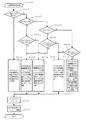
以下添付の図面に基づき本発明の好適な実施形態を説明する。図1は本発明の一実施例に係る遊技機全体の正面図、図2は同遊技機の遊技盤の正面図、図3は同遊技機のシステム制御を簡略に示すブロック図、図4は同遊技機の表示制御を簡略に示すブロック図である。
【0020】
本実施例において、語句の対応は以下の通りである。
可変図柄とは、図15等に表す画像表示部51(可変図柄表示領域に相当)に可変表示されるVL,VM,VRである。
特定図柄とは、図15等に表す配列図柄表示部61(配列図柄表示領域に相当)に配列されるZ1〜Z9である。
有効ラインとは、図15等に表す配列図柄表示部61上に形成される縦、横、斜めの直線E1〜E8であり、特定図柄の明示により形成されるものである。
特典遊技とは、実施例における大当たり遊技を示し、大入賞口の開閉、賞品球として遊技球が払い出される等の賞価値が付与される遊技状態である。
入球領域とは、図1及び図2に表す始動入賞口10である。
なお、請求項の語句と本実施例の語句との対応は、以上の通りであるが、本実施例は請求項の一実施例であり、請求項の内容が以下の実施例に限定されるものではない。
【0021】
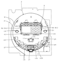
図1及び図2に示す遊技機(ここではパチンコ遊技機)1は、遊技盤3の縁に遊技球の外側誘導レール4及び内側誘導レール5が略円形に立設され、前記内側誘導レール5によって囲まれた遊技領域6の中心線上にその上部から下部に向かって順に表示装置9、始動入賞口10及び可動部材11a,11b、特別電動役物である大入賞口15、アウト口17が配設される。前記表示装置9の両側に普通図柄変動開始用左ゲート19及び普通図柄変動開始用右ゲート21、その左右下方に左袖入賞口23と右袖入賞口25、さらには前記大入賞口15の両側に左落とし入賞口27と右落とし入賞口29が配設されている。前記種々の入賞口に遊技球が入賞すると所定数の遊技球が賞品球として払い出される。また、後に詳述する特定の条件で大当たり遊技、この例では大当たりとなると大入賞口15が開放され、遊技球が入賞し易い状態となる。また、左,右普通図柄変動開始用ゲート19,21においては遊技球通過の検出信号により、普通図柄(図示せず)が所定値となった場合、始動入賞口10(可動部材11a,11b)が拡開状態となる。
【0022】
前記遊技盤3の前面側には、払い出された遊技球を受けるための上側球受け皿32、該上側球受け皿32を取り付けるための取付板33、前記上側球受け皿32の飽和時に遊技球を受けるための下側球受け皿34、遊技状態を報知するランプ表示器35,36及び飾りランプ39L,39R、音声や効果音を発して遊技状態を遊技者に報知するスピーカ37、遊技者の発射ハンドルHがそれぞれ組み付けられている。符号2は遊技機の機枠である。次に所要の各部についてさらに詳述する。
【0023】
前記表示装置9には、液晶、ドットマトリックスもしくはLED表示装置等の表示装置からなる図柄表示装置50と、特定図柄を適宜発光点灯により明示可能にする配列図柄表示装置60が設けられる。実施例では、窓枠部49内にカラー表示可能な液晶表示器(TFT−LCDモジュール)等からなる画像表示部(可変図柄表示領域)51が設けられている。前記画像表示部51は、複数の数字、アルファベット、記号あるいは絵(キャラクタ)等からなる図柄(実施例においては複数の可変図柄)を可変表示する表示手段に相当する。また、前記窓枠部49内において、配列図柄表示装置60は、アクリル樹脂、ガラス等の透光性を有する透光部材に複数の特定図柄が配列して記載された配列図柄表示部61(配列図柄表示領域)とその裏面より照らすLED(図示せず)より構成される。実施例では、遊技者の視認性を考慮して画像表示部(可変図柄表示領域)51と配列図柄表示部61(配列図柄表示領域)は、互いに区画して形成される。前記配列図柄表示装置60は、図柄表示装置50と同様に表示手段に相当する。
【0024】
さらに、前記表示装置9にはLED等からなる普通図柄保留記憶数表示器47が設けられる。普通図柄保留記憶数表示器47は、前記左,右普通図柄変動開始用ゲート19,21を遊技球が通過することによって取得する図柄変動停止に係わる情報(乱数値)を、現在変動中のものを除いて保留記憶数(この例では最高4回)を表示するものである。
【0025】
また、前記遊技盤3の背面には、始動入賞口10に入賞(入球)した遊技球を検出する可変図柄変動開始スイッチ(図示せず)が入賞球の通路に設けられており、該入賞球の検出によって前記図柄表示装置50の図柄変動を開始するようになっている。その際、可変図柄変動中に始動入賞口10に入賞した遊技球の個数、すなわち可変図柄の変動を開始する回数については、保留記憶数(この例では最高4回)を、前記可変図柄保留記憶数表示器48に表示し、記憶数の減少によって前記表示器48の表示個数を減らす(色を変化させる)ようになっている。
【0026】
図15等に表す通り、前記画像表示部51は、可変図柄のうち、左可変図柄を表示する左可変図柄表示領域51l、中可変図柄を表示する中可変図柄表示領域51m、右可変図柄を表示する右可変図柄表示領域51rに三分割され、それぞれの図柄表示領域には、識別可能な図柄を構成するそれぞれの可変図柄が個々独立して変動(可変)及び停止表示可能とされている。前記可変図柄は、図15等に示すように、『‘1’,‘2’,‘3’,‘4’,‘5’,‘6’,‘7’,‘8’,‘9’』の9通りで構成されている。なお、前記画像表示部51の左端には、普通図柄表示領域41が設けられ、普通図柄(図示せず)が変動表示及び停止表示される。
【0027】
前記画像表示部51内で特別図柄が変動中には、可変図柄の背後に図示はしないが建物、風景、人物、動物、植物、物、文字等の背景画像が表示され、可変図柄の変動及び停止の表示が効果的に演出される。
【0028】
併せて、図15等に表す通り、配列図柄表示部61(配列図柄表示領域)内には、『‘1’,‘2’,‘3’,‘4’,‘5’,‘6’,‘7’,‘8’,‘9’』の9通りの特定図柄が、「3行3列の行列」を成したマトリックス状に配置される。前記配列図柄表示部61内には、縦、横、斜めからなる8本の有効ラインE1〜E8が設定され、各有効ラインには、3個の特定図柄が包含される。
実施例において、左,中,右可変図柄がぞろ目として停止表示された場合に可変図柄と同一の特定図柄が明示される。例えば、左,中,右可変図柄が『555』のぞろ目である場合、特定図柄『5』が明示され、大当たり遊技(特典遊技)が実行されるまで、その明示は継続される。
【0029】
前記始動入賞口10は表示装置9の真下に設けられ、実施例の遊技機における入球領域に相当する。当該始動入賞口10には、2つの駆動部材11a,11bが背面の始動入賞口用ソレノイドによって通常状態である略垂直の狭小開放状態と略V字形の拡大開放状態の間を変化可能に駆動制御されている。前記始動入賞口10の拡大開放は、前記普通図柄表示領域41の普通図柄が変動停止して特定の普通図柄が表示された普通図柄当たりとなったときに行われる。実施例では、遊技状態時における普通図柄表示領域41の停止普通図柄が当たりである特定図柄の場合には、0.5秒間の始動入賞口10の拡大開放を1回行う。
【0030】
前記左,右普通図柄変動開始用ゲート19,21は表示装置9の両側に設けられ、普通図柄変動開始スイッチを備え、該普通図柄変動開始スイッチで両通過ゲート19,21を通過する遊技球を検出することによって前記普通図柄表示領域41の普通図柄の変動を開始させるようになっている。また、前記左袖入賞口23と右袖入賞口25の入賞球を検出する左袖入賞口用検出スイッチと右袖入賞口用検出スイッチ、前記左落とし入賞口27と右落とし入賞口29の入賞球を検出する左落とし入賞口用検出スイッチと右落とし入賞口用検出スイッチが、図示はしないがそれぞれ対応する遊技盤背面に設けられている。
【0031】
前記大入賞口15は始動入賞口10の下方に設けられ、大入賞口開放用ソレノイドと該ソレノイドによって開閉する開閉板101とを備えている。この大入賞口15は、通常は開閉板101が閉じた状態とされ、当該大入賞口15の内部には、該大入賞口15の開放と同時に開放して入賞可能にする特定領域入賞口103を有する。さらに、該特定領域入賞口103には、所定条件時に特定領域開放用ソレノイドにより開閉される開閉扉(図示せず)が設けられている。また、前記特定領域入賞口103には特定入賞球を検出する特定入賞球検出スイッチが設けられ、該入賞球の検出により大入賞口15を再度開ける継続権利が成立するようにされている。また、大入賞口15内の略中央には、前記大入賞口15に入賞しかつ前記特定領域入賞口103に入賞しなかった入賞球を検出する入賞球数カウントスイッチが設けられている。
【0032】
前記図柄表示装置50、つまり、中当たり成立時の動作について説明する。前記のように始動入賞口10に遊技球が入賞(入球)し、可変図柄変動開始スイッチによって入賞球が検出されると、前記特別図柄変動開始スイッチにより入球信号が後述する図3に示すメイン制御回路70へ送られ、それに伴ってメイン制御回路70のラベル−TRND−A等の各種乱数値(Q1等)が取得(抽出)され、その取得数値がメイン制御回路70のRAMの可変図柄乱数記憶領域等に一旦格納される。そして、当該格納された各数値に基づいて大当たりの判定、リーチの有無決定、可変図柄の変動・停止パターン、可変図柄の停止図柄組合せの決定(作成)等が行われ、前記図柄表示装置50における画像表示部51の各所定表示領域で可変図柄の変動を開始する。前記メイン制御回路70は、遊技機1のメイン制御を行うメイン制御手段に相当するものである。
【0033】
前記可変図柄は、変動開始から所定時間(この例では最低約5秒から最高50秒)変動後、停止可変図柄として画像表示部51(図15等に図示)に確定停止表示される。実施例中の1つの変動態様では、まず、左可変図柄表示領域51l、中可変図柄表示領域51m、右可変図柄表示領域51rにおいて前記可変図柄が変動を開始し、左可変図柄表示領域、右可変図柄表示領域、中可変図柄表示領域の順に可変図柄が変動停止して停止図柄として確定停止表示される。その際、決定された可変図柄の表示態様等によっては、リーチ状態が成立することがある。
【0034】
ここで、リーチ状態とは、画像表示部51の左,中,右可変図柄表示領域において、可変図柄の変動表示が開始された後、表示制御が進行して表示結果が停止表示される前段階において、特定の表示態様、つまり大当たり図柄の組合せ(同一図柄の組合せ)が表示され易い可変表示態様となったと遊技者に思わせるための表示態様をいう。この実施例では、リーチ状態の1つとして、前記画像表示部51の左,中,右可変図柄表示領域のうち、最終停止図柄(ここでは中可変図柄)を表示する表示領域(ここでは中可変図柄表示領域)だけを残して、残りの2つの表示領域で図柄が特定の組合せ(例えば同一図柄)となるように仮停止するリーチ変動表示処理がなされている。
【0035】
また、前記リーチ状態時には、前記画像表示部50における可変図柄(主に最終停止可変図柄)の変動時間を長くしたり、前記画像表示部50における可変図柄を利用した図柄利用演出や可変図柄の背後に表示されるキャラクタや背景等を表示してリーチアクションが演出されるようになっている。なお、前記リーチ状態になる前に、該リーチ状態になる可能性又は大当たりになる可能性が高いことを報知する予告(予兆)が演出されるようにしてもよい。前記予告としては、画像表示部50上へのキャラクタの表示や残像表示等が挙げられる。
【0036】
前記停止図柄(確定停止した可変図柄)の組合せが、同一図柄等の組合せからなる当たり図柄組合せ(ぞろ目)となると、中当たり状態を意味する中当たり遊技に移行する。前記中当たり状態になると、所定の賞品球の払い出しが行われると共に、前記配列図柄表示部61内で可変図柄と一対一で対応する特定図柄(実施例にあっては可変図柄『1』と特定図柄『1』のように一致する図柄同士)がLEDの点灯により明示される。
【0037】
前述の中当たりを何回か経ることにより、特定図柄が少なくとも3個以上明示され、所定の組合せとして図15等に示す8本の有効ラインのいずれか1本を形成した場合、ビンゴゲームは成立する。これに続き、前記大入賞口15の開閉板101が開いて遊技領域6表面を落下してくる遊技球を受け止め、大入賞口15へ入賞可能にし、該大入賞口15への入賞があると、賞球払出装置により所定数の遊技球が賞品球として払い出される等の賞価値の付与可能な特典遊技(実施例における大当たり遊技)に移行制御される。
【0038】
前記開閉板101は、所定時間(例えば29.5秒)経過後、あるいは入賞球数カウントスイッチで検出された入賞球数が所定個数(例えば10個)となった時点で一旦閉じ、大入賞口への入賞球数を正確(例えば10個)に計測するようにされている。このような、前記開閉板101の開放に伴う遊技球が入賞し易くなる状態と開閉板101が閉鎖される状態とは組み合わされて、1回のラウンドとして数えられる。実施例の遊技機における大当たり遊技(特典遊技)では、前記ラウンドは所定最高回数(15回)実行される。なお、前記入賞球数カウントスイッチで検出された入賞球数は、図柄表示装置50の画像表示部51に、0〜10までの数字又は棒グラフのように表示されるようになっている。
【0039】
実施例では、通常の始動入賞口10への入賞(入球)に起因する可変図柄の変動表示(例えば、リーチ態様)及び特定図柄の明示態様(例えば、ビンゴゲーム成立)に対し、これに関係する音声の発生及び発光が行われ、遊技の演出効果を高めている。
【0040】
図3に示すメイン制御回路(主制御手段)70は、CPU,RAM,ROMを備えたコンピュータと、該コンピュータから送信された制御信号を受信し、その制御信号に基づいて所定の処理を行う表示制御回路(サブ制御手段)90等を結ぶ入出力回路と、前記コンピュータと大入賞口15に接続される中継回路等を結ぶ入出力回路等で構成される。実施例において、前記メイン制御回路70は、賞価値を付与可能に移行制御する賞価値付与移行制御手段に相当する。
【0041】
前記メイン制御回路70におけるCPUは、制御部,演算部,各種カウンタ,各種レジスタ,各種フラグ等を備え、演算制御を行う他、必要に応じて中当たりの発生確率や小当たり(実施例においては、始動入賞口10の拡開開放を行う普通図柄当たり)の発生確率を定める乱数等を生成することもある。また、前記RAMは、可変図柄変動開始スイッチ(図示せず)の検出信号及び普通図柄変動開始スイッチ(図示せず)の検出信号用の記憶領域,CPUで生成される各種乱数値用の記憶領域,各種データを一時的に記憶する記憶領域やフラグ領域,CPUの作業領域,各種バッファを備えている。さらに、前記ROMには、遊技上の制御プログラムや制御データが書き込まれている他、後述する各遊技状態における大当たり及び小当たりの判定値等が書き込まれている。また、前記普通図柄表示領域41における図柄変動の制御は、メイン制御回路70によって行われる。なお、図3中の符号105は賞球払出装置、106は球貸装置である。
【0042】
表示制御回路90は、遊技機1の表示制御手段、仮停止表示制御手段、演出表示制御手段等に相当し、表示装置9(特に画像表示部51)に表示される遊技画像(可変図柄の他、図示はしないが普通図柄,背景画像,キャラクタ画像,文字画像等が含まれる。)の表示制御を行うためのものである。前記表示制御回路90にもメイン制御回路と同様にCPU,RAM,ROMを備えたコンピュータ及び入出力回路等が適宜備えられ、メイン制御回路の指令に基づいて各種演算が実行されて遊技画像が作成される。
【0043】
さらに、配列図柄明示制御回路80は、遊技機1の表示制御手段に相当し、特定図柄の配列図柄表示部61への明示(LED点灯)を制御するものである。前記配列図柄明示制御回路90にもメイン制御回路と同様にCPU,RAM,ROMを備えたコンピュータ及び入出力回路等が適宜備えられ、メイン制御回路の指令に基づいて各種演算が実行されて特定図柄が明示(特定図柄に該当する箇所のLEDが点灯)される。
【0044】
前出の回路の他に、報知するランプ表示器35,36、飾りランプ39L,39R等の各種発光体を制御する発光制御回路、スピーカ37の音声の発生を制御する音声制御回路等等が設けられる。
【0045】
この実施例における前記メイン制御回路70のCPUの主なカウンタとしては、表1に示すような6種類のカウンタがある。各カウンタの所定時に取得された数値は、メイン制御回路70のRAMに最高4個まで格納される。なお、前記RAMに記憶された各カウンタの数値は、該カウンタに基づく一連の遊技動作処理された後にクリアされる。各カウンタの作動については次に示す。
【0046】
【表1】

ラベル−TRND−Aは、中当たり及び外れを判定する乱数カウンタであり、当該遊技機1における中当たり当否判定手段に相当するものである。このラベル−TRND−Aは、遊技機1の電源投入時、‘0’から始まり、所定の割り込み時間(例えば4msec)毎に1ずつ加算され、数値が‘49’に至ると、再び‘0’に戻って前記加算を繰り返すようになっている。ラベル−TRND−Aの数値は、遊技球が始動入賞口10に入賞(入球)して可変図柄変動開始スイッチによって検出されたときに取得され、予め決定されている中当たり数値、実施例では‘5’と対比され、中当たりか否か判断される。また、当否の判定が終了するまでの間に、遊技球が始動入賞口10に入賞してラベル−TRND−Aの数値が再び取得されることがあるため、ラベル−TRND−Aの記憶取得値(更新取得数値)は、現在判定中の取得値を含めず最大4個が、前記メイン制御回路70のRAMに一旦格納され、順次判定に供される。
【0048】
ラベル−TRND−R1は、前記ラベル−TRND−Aによる中当たり当否判定結果が外れとなる場合において、リーチ状態となるか否かを決定するものであり、具体的には前記画像表示部51の左,中,右可変図柄表示領域51l,51m,51rのうち、最終停止図柄表示領域(この例では中可変図柄表示領域)だけを残して、残りの2つの表示領域において可変図柄が特定の組合せ(この例では同一図柄)で仮停止表示(停止表示)されるか否かを決定するものである。ここで、前記仮停止表示とは、リーチにおいて可変図柄が一旦停止表示されたと遊技者に思わせるが、まだ図柄変動中であること、つまり、まだ全可変図柄が確定停止されていないことを示す変動表示である。
【0049】
このラベル−TRND−R1は、遊技機1の電源投入時、‘0’から始まり、前記割り込み時間毎に1ずつ加算され、数値が‘49’になると、再び‘0’に戻って前記加算を繰り返すようになっている。当該ラベル−TRND−R1の数値は、前記始動入賞口10への入賞(入球)が可変図柄変動開始スイッチによって検出されたときに取得され、中当たり当否判定結果が外れの場合に、その数値が予め決定されているリーチ成立数値と対比されてリーチ状態成立か否か判断される。この実施例では、前記リーチ成立数値は‘24’又は‘49’となっており、ラベル−TRND−R1の取得数値が当該リーチ成立数値となった場合には、可変図柄においてリーチ状態が成立する。当該ラベル−TRND−R1の取得数値は、メイン制御回路70のRAMに所定数、この例では、決定中の数値を含めず最大4個まで格納される。なお、この実施例では、前記ラベル−TRND−Aによる大当たり当否判定結果が大当たりとなる場合、必ず可変図柄にはリーチ状態が成立するようになっているので、このラベル−TRND−R1は使用されない。
【0050】
ラベル−TRND−AZ1は、中当たり成立時、前記画像表示部51における左可変図柄表示領域51l、中可変図柄表示領域51m、右可変図柄表示領域51rに確定停止して揃う確定大当たり停止可変図柄組合せを決定するものである。ラベル−TRND−AZ1は、電源投入時に‘0’から始まって前記割り込み時間毎に‘1’ずつ加算され、‘8’に至ると再び‘0’に戻る繰り返しを行う。ラベル−TRND−AZ1の数値は、前記始動入賞口10への入賞(入球)が可変図柄変動開始スイッチによって検出されたときに取得され、変動表示中の図柄に対するものを含めず最大4個までメイン制御回路70のRAMの可変図柄乱数記憶領域に格納される。前記ラベル−TRND−AZ1の数値には、各数値に対応する確定大当たり停止図柄組合せ(可変図柄組合せ)が予め割り当てられている。実施例においては、‘0’の場合には『111』、‘1’の場合には『222』、‘2’の場合には『333』、‘3’の場合には『444』、‘4’の場合には『555』、‘5’の場合には『666』、‘6’の場合には『777』、‘7’の場合には『888』、‘8’の場合には『999』を確定中当たり停止図柄組合せとして最終的に確定停止表示する。
【0051】
ラベル−TRND−B1〜B3は、前記ラベル−TRND−Aによる中当たり当否判定結果が外れとなる場合において、画像表示部51に確定停止表示する外れ可変図柄組合せの決定に用いられるものである。可変図柄組合せにあっては、前記ラベル−TRND−B1は左可変図柄表示領域51lにおける左可変図柄、ラベル−TRND−B2は右可変図柄表示領域51rにおける右可変図柄、ラベル−TRND−B3は中可変図柄表示領域51m(最終停止図柄表示領域)における中可変図柄にそれぞれ対応する。
【0052】
前記ラベル−TRND−B1は、電源投入時に‘0’から始まって前記割り込み時間毎に‘1’ずつ加算され、‘8’に至った後、再び‘0’から始まって加算が繰り返される。また、前記ラベル−TRND−B2は、電源投入時に‘0’から始まって、前記ラベル−TRND−B1の数値が再び‘0’に戻る際に‘1’ずつ加算され、‘8’に至った後、再び‘0’から始まって加算が繰り返される。さらに、前記ラベル−TRND−B3は、電源投入時に‘0’から始まって、前記ラベル−TRND−B2の数値が再び‘0’に戻る際に‘1’ずつ加算され、‘8’に至った後、再び‘0’から始まって加算が繰り返される。これによって、ラベル−TRND−B1〜B3の各乱数範囲が同一であっても、当該ラベル−TRND−B1〜B3が同期(同一の組合せで加算)するのを避けることができる。
【0053】
前記ラベル−TRND−B1〜B3の数値には、各数値に対応する図柄が予め割り当てられている。この実施例では、ラベル−TRND−B1〜B3の各取得数値に対し、数値が‘0’の場合には『1』、‘1’の場合には『2』、‘2’の場合には『3』、‘3’の場合には『4』、‘4’の場合には『5』、‘5’の場合には『6』、‘6’の場合には『7』、‘7’の場合には『8』、‘8’の場合には『9』が割り当てられている。そして、前記可変図柄変動開始スイッチによって入球が検出される毎にラベル−TRND−B1〜B3から取得される数値の組合せによって、外れ時に画像表示部51に表示される確定停止図柄が定まる。また、ラベル−TRND−B1〜B3の取得数値は、メイン制御回路70のRAMに所定数、この例では、変動表示中の外れ可変図柄組合せに対する数値を含めず最大4個まで格納される。
【0054】
この実施例では、外れの際にラベル−TRND−B1〜B3の全ての数値が一致し、かつラベル−TRND−R1の数値によりリーチ状態が成立する場合には、ラベル−TRND−B3の数値に1加算し、その値とラベル−TRND−B1,B2の数値に割り当てられている各可変図柄が確定停止表示されるようになっている。また、外れの際にラベル−TRND−B1〜B3の全ての数値が一致し、かつリーチ状態が成立しない場合、及びラベル−TRND−B1,B2の2つの数値が一致し(ラベル−TRND−B3の数値は異なる。)、かつリーチ状態が成立しない場合には、ラベル−TRND−B2の数値に1加算し、その値とラベル−TRND−B1,B3の数値に割り当てられている各可変図柄が確定停止表示されるようになっている。さらに、外れの際にラベル−TRND−R1の数値によりリーチ状態が成立するにも係わらず、ラベル−TRND−B1とB2の数値が一致しない場合には、ラベル−TRND−B2の数値をラベル−TRND−B1の数値と同一数値に変更すると共に、ラベル−TRND−B3の数値を前記ラベル−TRND−B1の数値に1加算した数値に変更し、それらの変更した値とラベル−TRND−B1の数値に割り当てられている各可変図柄が確定停止表示されるようになっている。
【0055】
前記メイン制御回路70、表示制御回路90に設けられるカウンタとしては、可変図柄の変動時におけるその他の表示態様、例えば、リーチ変動の種類を決定するカウンタ、中当たり又はリーチ状態となる可能性が高いことを報知するための予告を演出するか否かを決定するカウンタ、該予告の態様を決定するカウンタ、確定当たり図柄組合せの確定停止表示前に、画像表示部51に仮の当たり図柄組合せ(ここではぞろ目)を微妙な揺れ変動等の所定動作態様で仮停止表示し、その後、前記仮停止によって一旦揃った全ての特別図柄を、図柄が揃った状態のまま一緒に所定時間スクロール変動させてから、前記確定当たり図柄組合せを確定停止表示する、所謂再抽選演出を行うか否かを決定するカウンタ、普通図柄とその当否判定を決定するカウンタ等が適宜追加されることがある。
【0056】
また、前記メイン制御回路70、表示制御回路90及び配列図柄明示制御回路80等に設けられる複数のフラグとしては、大当たりフラグA1、中当たりフラグB1、リーチフラグC1、大当たり遊技実行中フラグD1に加え、判定フラグf1,f2,f3,f4,f5,f6,f7,f8等が挙げられる。なお、これらのフラグは、初期設定時には全て0にセットされている。
【0057】
次に、本発明に係る遊技機1において前記メイン制御回路70が行う一連の処理について、前記カウンタとの関係から詳述する。なお、図3に示したメイン制御回路70のCPUは、割り込み時間(4msec)毎にメイン制御回路70のROMに記憶されている各プログラム(メインルーチン)を実行する。
【0058】
図4のフローチャートから理解されるように、メイン処理Mにおいては、まず、電源投入がなされたか否か確認されてから(S10)、初期設定(S20)、出力処理(S30)、入力処理(S40)、乱数更新処理(S50)、始動入賞口10への入球確認(S60)、乱数取得処理(S70)、中当たり当否判定条件(可変図柄始動条件)成立の確認(S80)、中当たり当否判定及び中当たり設定処理(S90)、リーチ決定処理(S100)、可変図柄決定処理(S110)、特定図柄明示決定処理(S130)、大当たり当否判定及び大当たり設定処理(S140)、大当たり遊技実行処理(S150)、その他の処理(S200)が行われる。
【0059】
初期設定(S20)では、スタックの設定、定数設定、CPUの設定、SIO,PIO,CTCの設定等を行う。なお、電源投入時のみに必要な処理は1順目のみに実行され、後は実行されることがない。
【0060】
出力処理(S30)では、図5のフローチャートから理解されるように、前記メイン制御回路70のRAM中の出力バッファ内に出力データの有無が確認され(S31)、出力データがある場合には、当該出力バッファ内の出力データが出力される(S32)。出力データがない場合には、データの出力は行われず終了する。なお、前記出力データには、停止図柄指定コマンド、明示図柄指定コマンド等があり、各コマンドは、表示制御回路90、配列図柄明示制御回路80、音声制御回路、発光制御回路等に送信される。
【0061】
入力処理(S40)では、始動入賞口10、左,右普通図柄変動開始用ゲート19,21、大入賞口15等に取り付けられたスイッチ(センサ)が遊技球を検出した場合に遊技に関する各種データ等の入力処理が行われる。
【0062】
乱数更新処理(S50)では、図6のフローチャートから理解されるように、各カウンタ(ラベル−TRND−B2,B3を除く。)の各数値Qn(n=1〜4)が前記所定時間毎に1ずつ加算され(S51)、前記各数値Qnが所定最大値X(ラベル−TRND−Aの場合は49、ラベル−TRND−R1の場合は49、ラベル−TRND−AZ1の場合は8、ラベル−TRND−B1の場合は8)に至ると次に再び‘0’に戻る繰り返しを行う(S52,S53)。そして、各カウンタの更新数値がメイン制御回路70のRAMの各カウンタと対応する乱数記憶エリアにそれぞれ記憶される(S54)。図6中における『Qn’』は、加算(更新)される前の各カウンタの数値を意味する。なお、各カウンタは割り込み時間(4msec)毎に1ずつ加算され、ラベル−TRND−B2はラベル−TRND−B1に連動して数値Q5が加算され、ラベル−TRND−B3はラベル−TRND−B2に連動して数値Q6が加算され、前記RAMの乱数記憶エリアにそれぞれ記憶されるようになっている。
【0063】
前記乱数更新処理(S50)の後、始動入賞口10に入賞(入球)があったか否かが可変図柄変動開始スイッチの検出により確認される(S60)。そして、前記始動入賞口10への入賞ありと判断された場合には、乱数取得処理(S70)が実行される。なお、前記S60で入賞なしと判断された場合には、乱数取得処理(S70)は省略される。
【0064】
乱数取得処理(S70)では、図7のフローチャートから理解されるように、まず、ラベル−TRND−A,ラベル−TRND−R1,ラベル−TRND−AZ1,ラベル−TRND−B1〜B3の更新数値Qn(n=1〜6)が取得され(S71)、次いで、前記取得された各数値Qnは、メイン制御回路70のRAMの取得乱数記憶エリアに各々記憶される(S72)。
【0065】
前記乱数取得処理(S70)の後、中当たり当否判定条件が成立しているか否かが確認される(S80)。ここで、中当たり当否判定条件が成立しているとは、現在大当たり遊技実行中でない、あるいは可変図柄変動中でないことをいう。
そして、前記中当たり当否判定条件成立と判断された場合には、以降、中当たり当否判定及び中当たり設定処理(S90)、リーチ決定処理(S100)、可変図柄決定処理(S110)、特定図柄明示決定処理(S130)、大当たり当否判定及び大当たり設定処理(S140)、大当たり遊技実行処理(S150)、その他の処理(S200)が行われる。一方、前記S80で中当たり当否判定条件不成立と判断された場合は、大当たり当否判定及び大当たり設定処理(S140)に移行し、上記した中当たりに関する処理(S90,S100,S110,S130)はなされない。
【0066】
中当たり当否判定及び中当たり設定処理(S90)では、図8のフローチャートから理解されるように、前記ラベル−TRND−Aの取得数値Q1が中当たり数値である‘5’と対比され(S91)、前記中当たり数値に該当するならば中当たりとなり、中当たりフラグB1が1にセットされると共に、該中当たりフラグB1(=1)がメイン制御回路70のRAM内に格納される(S92)。なお、前記中当たり数値に該当しない場合は、そのまま終了する。
【0067】
リーチ決定処理(S100)においては、リーチの有無、つまり、図柄表示装置50の画像表示部51でリーチ状態(可変図柄が及びリーチ外れ)となるか否かの決定がなされる。図9のフローチャートから理解されるように、このリーチ決定処理(S100)では、最初に中当たりフラグB1が1か否か確認され(S101)、中当たりフラグB1が1ではなく0、つまり中当たり不成立となる場合、前記ラベル−TRND−R1の記憶取得数値Q2が読み出され、その取得数値Q2が‘24’又は‘49’であるか否か判断される(S102)。そして、両値が一致しない場合、リーチ無し(リーチ状態移行不可)となることが決まる。一方、前記取得数値Q2が‘24’又は‘49’である場合、リーチ有り(リーチ状態移行可)となることが決定し、リーチフラグC1が1にセットされると共に、該リーチフラグC1(=1)がメイン制御回路70のRAM内に格納される(S103)。また、前記S101において中当たりフラグB1が1の場合、つまり中当たりとなる場合にも、リーチ有りとなることが決定し、リーチフラグC1が1にセットされると共に、該リーチフラグC1(=1)がメイン制御回路70のRAM内に格納される(S103)。
【0068】
可変図柄決定処理(S110)では、前記中当たり当否判定及び中当たり設定処理(S90)に基づき図柄表示装置50の画像表示部51に確定(最終)停止表示する可変図柄の決定が行われる。図10のフローチャートから理解されるように、この可変図柄柄決定処理(S110)では、まず、前記中当たりフラグB1の値が1か否か判断される(S111)。該値が1と判断された場合、すなわち中当たりとなる場合、前記ラベル−TRND−AZ1の記憶取得数値Q3が読み出され、その取得数値Q3に対し、前記した予め決められている図柄の組合せ(可変図柄にあっては、例えば『1』のぞろ目等)が、画像表示部51確定停止表示される確定大当たり停止図柄組合せとして決定される(S112)。当該決定後、リーチフラグC1の値が0にセットされる(S113)と共に、決定された確定大当たり停止可変図柄組合せのデータは、メイン制御回路70(ワンチップマイクロコンピュータ)内のRAMの出力バッファに格納される(S114)。
【0069】
それに対して、前記S111で中当たりフラグB1の値が1でない、すなわち前記値が0と判断され、中当たり外れと判定された場合には、前記ラベル−TRND−B1〜B3の記憶取得数値Q4〜Q6が読み出され、その読み出された全数値Q4〜Q6が一致するか否か判断される(S115)。全数値Q4〜Q6が一致する場合、続いてリーチ有り(前記リーチフラグC1=1)か否か、ここでは前記ラベル−TRND−R1の記憶取得数値Q2が‘24’又は‘49’か否か判断される(S116)。そして、リーチ無し(リーチフラグC1=0)と判断された場合、前記ラベル−TRND−B2(右可変図柄用)の取得数値Q5を1加算し、その値とラベル−TRND−B1,B3の取得数値Q4,Q6に対して予め決められている図柄が、画像表示部51の各表示領域に確定停止表示される外れ可変図柄組合せとして決定される(S117)。一方、前記S116で、リーチ有り(リーチフラグC1=1)と判断された場合、前記ラベル−TRND−B3(中可変図柄用)の取得数値Q6を1加算し、その値とラベル−TRND−B1,B2の取得数値Q4,Q5に対して予め決められている可変図柄が、各表示領域に確定停止表示される外れ可変図柄組合せとして決定される(S118)。
【0070】
また、前記S115において、ラベル−TRND−B1〜B3の取得数値Q4〜Q6のうち、少なくとも1つが異なる数値となる場合には、ラベル−TRND−B1の取得数値Q4とラベル−TRND−B2の取得数値Q5が一致するか否か判断され(S119)、両値が一致する場合、さらにリーチ有り(リーチフラグC1=1)か否か判断される(S120)。そして、リーチ無し(リーチフラグC1=0)と判断された場合、前記ラベル−TRND−B2の取得数値Q5を1加算し、その値とラベル−TRND−B1,B3の取得数値Q4,Q6に対して予め決められている可変図柄が、画像表示部51の各表示領域に確定停止表示される外れ可変図柄組合せとして決定される(S117)。一方、前記S120において、リーチ有り(リーチフラグC1=1)と判断された場合、ラベル−TRND−B1〜B3の取得数値Q4〜Q6に対して予め決められている可変図柄が、各表示領域に確定停止表示される外れ可変図柄組合せとして決定される(S121)。
【0071】
さらに、前記S119において、ラベル−TRND−B1の取得数値Q4とラベル−TRND−B2の取得数値Q5が一致しない場合、続いてリーチ有り(リーチフラグC1=1)か否か判断される(S122)。そして、リーチ有り(リーチフラグC1=1)と判断された場合には、ラベル−TRND−B2の取得数値Q5をラベル−TRND−B1の取得数値Q4と同一数値に変更し、かつラベル−TRND−B3の取得数値Q6を前記ラベル−TRND−B1の取得数値Q4に1加算した数値に変更し、それらの数値とラベル−TRND−B1の取得数値Q4に対して予め決められている可変図柄が、画像表示部51の各表示領域に確定停止表示される外れ可変図柄組合せとして決定される(S123)。一方、前記S122において、リーチ無し(リーチフラグC1=0)と判断された場合、ラベル−TRND−B1〜B3の取得数値Q4〜Q6に対し、前出の予め決められている可変図柄が、各表示領域に確定停止表示される外れ可変図柄組合せとして決定される(S121)。
【0072】
前記S117,S118,S121,S123において決定された後、リーチフラグC1の値が0にセットされる(S113)と共に、決定された確定大当たり停止可変図柄組合せのデータは、メイン制御回路70(ワンチップマイクロコンピュータ)内のRAMの出力バッファに格納される(S114)。
【0073】
特定図柄明示決定処理(S130)では、前記中当たり当否判定及び中当たり設定処理(S90)に基づき図柄表示装置50の画像表示部51に確定(最終)停止表示する可変図柄と一対一で対応する特定図柄の明示の決定が行われる。図11のフローチャートから理解されるように、この特定図柄明示決定処理(S130)では、前記ラベル−TRND−AZ1の取得数値Q3が特定図柄明示指令信号(コマンド)と共にメイン制御回路70のRAM中の出力バッファ内に格納される(S131)。
【0074】
大当たり当否判定及び大当たり設定処理(S140)では、判定フラグ内に大当たりを意味するビット値となったフラグの有無が確認されると共に、大当たりフラグA1の制御が行われる。図12のフローチャートから理解されるように、まず、中当たりフラグB1の値が1か否か、すなわち、前記S90の中当たり当否判定及び中当たり設定処理において、中当たりが成立したか否か確認され(S141)、該B1の値が1でなければ当該処理(S140)は終了する。そして、中当たりフラグB1の値が1である場合には、前記S110の可変図柄決定処理において確定(最終)停止表示図柄組合せとして決定された可変図柄に対応するビットデータに判定フラグfy(y=1〜8のいずれか)は設定される(S142)。すなわち、後述する明示処理(S340)により明示される特定図柄Z1〜Z9(図15等に図示)に対応するビットデータのビット値の更新が行われ、各判定フラグ毎にビット値の総和(論理和)が求められる。続いて、順次各判定フラグf1〜f8の設定終了が確認される(S143)。
【0075】
全ての判定フラグの設定が終了すると、判定フラグ領域中のビットデータ(ビット値の総和(論理和))が「2進法の111」となっている判定フラグの有無が確認される(S144)。前記判定フラグ領域中のビットデータ(ビット値の総和(論理和))が「2進法の111」となっている判定フラグがある場合、大当たりフラグA1が1にセットされると共に、該大当たりフラグA1(=1)がメイン制御回路70のRAM内に格納され(S146)、前記判定フラグfy(y=1〜8のいずれか該当するもの)のリセット(値を0にセット)される(S147)。続いて、中当たりフラグB1の値が0にセットされる(S148)。一方、判定フラグ領域中のビットデータ(ビット値の総和(論理和))が「2進法の111」となっている判定フラグがない場合には、各判定フラグf1〜f8の判定終了が確認され(S145)、中当たりフラグB1の値が0にセットされる(S148)。
【0076】
大当たり遊技実行処理(S150)においては、図13に示すように、最初に、大当たり遊技実行中フラグD1の値が1か否か判断され(S151)、該値が1でなければ、続いて、大当たりフラグA1の値が1か否か、つまり大当たりが成立しているか否か確認される(S152)。そして、前記大当たりフラグA1の値が1の場合には、前記配列図柄表示部61で大当たりとなったことを報知する大当たり表示(有効ラインの成立の明示)の終了、言い換えれば大当たり表示時間の終了を確認してから(S153)、前記大当たり遊技実行中フラグD1が1にセットされる(S154)と共に、前記大当たりフラグA1の値が0にセットされる(S155)。それと同時に、大当たり遊技実行手段(この例ではメイン制御回路70が相当する。)の指示に基づいて、前記大入賞口開放用ソレノイドの励磁により前記大入賞口15の開閉板101を開放して遊技領域6表面を落下してくる遊技球を受け止め、大入賞口15内へ入賞可能、すなわち大当たり遊技の実行を開始する(S156)。なお、前記151で大当たり遊技実行中フラグD1の値が1である場合は、S156の大当たり遊技の実行に移行する。また、S152で大当たりフラグA1の値が1でない場合及びS153で大当たり表示(有効ライン成立表示)時間が終了していない場合、直ちに大当たり遊技実行処理(S150)を終了する。
【0077】
具体的に前記大当たり遊技の実行時においては、前記開閉板101は、所定時間(例えば29秒)経過後、あるいは前記入賞球数カウントスイッチで検出された入球数が所定個数(例えば10個)となった時点で閉じるようにされている。
また、前記特定領域入賞口103への入球を特定入賞球検出スイッチが検出する毎に前記開閉板101の開放を再度繰り返す継続権利が発生し、前記開閉板61の開放を所定最高ラウンド数(例えば最高15ラウンド)繰り返す。そして、前記開閉板101の開放中に特定入賞球検出スイッチによる入球の検出が無いか、あるいは前記最高ラウンド数の開閉板101の開放が終了するかのいずれかの大当たり遊技終了条件が成立すると、大当たり遊技は終了する(S157,S158)。大当たり遊技の終了と共に配列図柄表示部における特定図柄の明示を解除するコマンドが発信(特定図柄明示解除処理)され(S159)、前記大当たり遊技実行中フラグD1の値が0にセットされる(S160)。前記大入賞口15への入球に対して、1個の入球につき所定数、実施例では15個の遊技球が賞球払出装置により賞品球として払い出される。
【0078】
また、メイン処理Mにおいては、上述した各処理の他、遊技状態時に必要となるその他の処理(S200)、例えば左,右普通図柄変動開始用ゲート19,21の通過の確認、普通図柄当たり当否判定処理、可変図柄変動態様決定処理、始動入賞口開放処理、表示装置表示処理、スピーカ発声処理、各種発光体発光処理、フラグ等のリセット、その他のエラーの処理等が行われて、爾後の処理に備えて待機状態となる。
【0079】
次に前記配列図柄明示制御回路80が行うメイン処理について説明する。図14のフローチャートから理解されるように、配列図柄明示制御回路におけるメインルーチン(S300)において、まず、電源投入がなされたか否か確認されてから(S310)、初期設定(S320)、入力処理(S330)、明示処理(S340)、その他の処理(S350)が行われる。
【0080】
初期設定(S320)は、前記メイン制御回路のメイン処理Mと同様にスタックの設定、定数設定、CPUの設定、SIO,PIO,CTCの設定等を行う。
なお、電源投入時のみに必要な処理は1順目のみに実行され、後は実行されることがない。
【0081】
入力処理(S330)は、メイン制御回路70から送信される明示図柄指定コマンド(例えば、前記Q3の取得数値等)をはじめとする各種入力データを配列図柄明示制御回路内のRAM内のバッファに蓄積する処理である。
【0082】
明示処理(S340)では、前記S340の入力処理により、配列図柄明示制御回路内のRAM内のバッファに蓄積された入力データの各種コマンドに基づく特定図柄の明示が決定され、特定図柄の明示時間が経過した時に、配列図柄表示装置において可変図柄と一対一で対応する特定図柄が明示される。
【0083】
その他の処理(S350)では、明示解除処理における大当たり後の明示解除の他、その他のエラーの処理等が行われて、爾後の処理に備えて待機状態となる。
【0084】
前記大当たり当否判定及び大当たり設定処理(S140)におけるビットデータ及びビット値の設定について、以下の表2を用いて説明する。
【0085】
【表2】
実施例の遊技機1は、後述する図15より理解されるように、E1〜E8の8本(n=8)の有効ラインと、前記大当たり遊技(特典遊技)が実行可能となるために当該有効ライン上に明示される特定図柄を3個(m=3)備える。前記遊技機1は、表2に示す通り、判定フラグf1〜f8からなるの8個のフラグ領域を有すると共に、各判定フラグのそれぞれのフラグ領域は、特定図柄Z1〜Z9の個々のビットデータからなる集合であり、少なくとも当該有効ライン上に明示される特定図柄の個数以上、すなわち3ビット以上のビットデータから構成される。当該ビットデータ中の各ビット値(2進法における数値0〜111のいずれかの値)は、表2に示す通り、各フラグ領域でZ1〜Z9の特定図柄毎に対応して設定されている。
【0087】
具体的に、特定図柄Z1に対してビット値は、「0,100」、Z1に対してビット値は、「0,100」、Z1に対してビット値は、「0,100」、Z2に対してビット値は、「0,10,100」、Z3に対してビット値は、「0,1,100」、Z4に対してビット値は、「0,10,100」、Z5に対してビット値は、「0,10」、Z6に対してビット値は、「0,1,10」、Z7に対してビット値は、「0,1,100」、Z8に対してビット値は、「0,1,10」、Z9に対してビット値は、「0,1」である。なお、ビット値について示した鍵括弧内の数値は2進法における数値であり、以下同様である。
【0088】
特定図柄の明示は、前出のメイン制御回路70におけるラベル−TRND−AZ1の取得数値Q3が0〜9のいずれかであるかの他、大当たり遊技実行コマンド等の各種データが配列図柄明示制御回路80において、S340の明示処理を経ることにより、該当する特定図柄Z1〜Z9のいずれかが明示される。明示に連動して、特定図柄Z1〜Z9の該当個所のビット値は、初期状態の「0」より上記の通り、明示状態の「1,10,100」のいずれかの値に変化される。なお、電源投入時及び前記大当たり実行処理(S150)の特定図柄明示解除処理(S159)において明示は解除されるため、前記S147の判定フラグのリセットにより、全てのビット値は初期状態である「0」に更新される。
【0089】
前記大当たり当否判定及び大当たり設定処理(S140)においては、逐一、各判定フラグ領域毎に特定図柄Z1〜Z9に対応するビット値の総和(論理和)が求められる。前出の表2から自明な通り、いずれかの判定フラグ領域中のビット値の総和(論理和)が「111」になるか否かにより、該当する判定フラグfy(y=1〜8のいずれか1個)は、1にセットされ、fy=1の判定フラグは、配列図柄明示制御回路内のRAM内に格納される。このようにビットデータ中における個々のビット値の変化を認識することにより、いずれの特定図柄が前記有効ライン上に明示されているのか、特定図柄の明示が所定の組合せ態様(実施例にあっては、有効ライン)に形成されているのかの遊技状況を容易に把握可能とすることができる。
【0090】
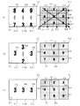
実施例の画像表示部51(可変図柄表示領域)に表示される可変図柄の変動態様及び配列図柄表示部61(配列図柄表示領域)に明示される特定図柄の明示態様の具体例、中当たり及び大当たりが成立する場合について図15及び図16を用いて説明する。
【0091】
図15(a)の表示例は、前記始動入賞口(入賞領域)10への入賞(入球)が可変図柄変動開始スイッチにより検出されると、前記メイン処理Mにしたがって図示されるように、前記画像表示部51における左,中,右可変図柄表示領域51l,51m,51rにおいて、左可変図柄VL,中可変図柄VM,右可変図柄VRの全図柄が上から下へ縦スクロール変動(可変表示)を始めた状態を表すものである。符号41は普通図柄表示領域であり、実施例においては、普通図柄の図示を省略する。
【0092】
一方、配列図柄表示部61においては、1〜9の数字からなる特定図柄Z1〜Z9は、「3行3列の行列」であるマトリックス状に配置され、特定図柄が明示されていない場合には、図示するように暗転(LED未点灯)されている。また、前記配列図柄表示部61においては、当該表示部に配置される特定図柄Z1,Z2,Z3の明示(LED点灯による明転)より有効ラインE1(矢印として図示)が成立する。同様に特定図柄Z4,Z5,Z6より有効ラインE2、特定図柄Z7,Z8,Z9より有効ラインE3、特定図柄Z1,Z4,Z7より有効ラインE4、特定図柄Z2,Z5,Z8より有効ラインE5、特定図柄Z3,Z6,Z9より有効ラインE6、特定図柄Z1,Z5,Z9より有効ラインE7、特定図柄Z3,Z5,Z7より有効ラインE8が成立する設定である。
【0093】
図15(b)の表示例は、前記S80における中当たり当否判定条件が成立し、S110の可変図柄決定処理によって、ラベル−TRND−AZ1の取得数値Q3に‘2’が選択され、リーチが演出されている一例である。具体的には前記画像表示部51の左,右可変図柄表示領域51l,51rにおいて、左,右可変図柄VL,VRが仮停止し、中可変図柄表示領域51mにおいて中可変図柄51mが変動を継続している状態である。
【0094】
図15(a),(b)の表示例では、いずれの特定図柄も明示されていないため、下記の表3に示す通り、いずれの判定フラグ領域中のビット値も「0」であり、その総和も当然「0」である。
【0095】
【表3】
図15(c)の表示例は、画像表示部51において、前出の図15(b)のリーチ状態から全可変図柄VL,VM,VR(『3』のぞろ目)が中当たり可変図柄組合せとして確定停止表示した状態である。この結果、前述のメイン処理(M)、配列図柄明示制御回路におけるメインルーチン(S300)内の各種処理を経て、配列図柄表示部61の特定図柄Z3が明示される。前記特定図柄Z3の明示箇所CLは他の特定図柄と比して明転(LED点灯による色調の変化)し、遊技者に明示を認識させるものである。同時に、下記の表4に示す通り、特定図柄Z3に対応する判定フラグ領域中のビット値が「1,100」に変更される。この場合のビット値の総和(論理和)は「0,1,100」であるため、いずれの有効ラインも成立していないと認識される。
【0097】
【表4】
図16(a),(b)の表示例は、さらに、画像表示部51において、リーチ状態から全可変図柄VL,VM,VR(『5』のぞろ目さらに『2』のぞろ目)が中当たり可変図柄組合せとして確定停止表示した状態である。この結果、可変図柄に連動して配列図柄表示部61の特定図柄Z5,Z2の明示箇所CLが広がる。同時に、下記の表5に示す通り、特定図柄Z2,Z5に対応する判定フラグ領域中のビット値が「10,100」及び「10」に変更される。この場合のビット値の総和(論理和)は「0,10,11,100」であるため、まだ、いずれの有効ラインも成立していないと認識される。
【0099】
【表5】
図16(c)の表示例は、またさらに、画像表示部51において、リーチ状態から全可変図柄VL,VM,VRが『7』のぞろ目からなる中当たり可変図柄組合せとして確定停止表示した状態である。同様に特定図柄Z7の明示箇所CLが広がり、有効ラインE8が成立する。同時に、下記の表6に示す通り、特定図柄Z7に対応する判定フラグ領域中のビット値が「1,100」に変更され、ビット値の総和(論理和)は「1,10,11,100,110,111」となる。この場合、ビット値の総和(論理和)に「111」が存在するため、判定フラグf8は1にセットされ、当たり特定図柄『357』からなる有効ラインE8の成立が確認される。有効ライン成立後、すなわち大当たり後は、前述のS150の大当たり遊技実行処理等に詳述した大当たり遊技に移行する。なお、実施例中、配列図柄表示領域61内の特定図柄の明示は大当たり遊技(特典遊技)が実行されるまで継続される。
【0101】
【表6】
上記実施例にあっては、画像表示部51における複数の可変図柄が全て同一、いわゆるぞろ目となることにより中当たりが成立し、該中当たりを契機として対応する特定図柄を明示させるものである。ここで、好適なカウンタ、フラグ等を適宜設けることにより、他の実施例として図17(a),(b)の態様が例示される。図17(a)の表示例は、左,右可変図柄VL,VRは共に『5』に、中可変図柄VMは『6』からなるリーチ外れで停止した可変図柄組合せを表すものである。このように停止した可変図柄においては、同一図柄種からなる左,右可変図柄VL,VRが2個であり、中可変図柄VMの図柄種より多い組合せの成立を契機として、例えば多い方の図柄種である特定図柄Z5を明示可能に設定してもよい。あるいは、図17(b)の表示例のように、停止した可変図柄が全て異なり、左,中,右可変図柄VL,VM,VRが1ずつ順に増しているような特定の組合せの成立を契機として、例えば中可変図柄VMに対応する特定図柄Z2を明示可能に設定することもできる。むろん、可変図柄及び特定図柄の表示態様はこれらに限られるものではない。
【0103】
実施例の遊技機においては、特典遊技の遊技例として大入賞口の開閉を伴う大当たり遊技を実行するものであるが、別途、ラウンド数選択処理、適宜のカウンタにより成立する確率変動フラグ、確率設定処理、普通図柄変動態様決定処理等を追加することにより、特典遊技の他の態様を演出可能とすることができる。
【0104】
当該遊技機の大当たり成立時、特定図柄の明示がいずれの有効ラインにおいて形成されているのかにより、前記ラウンドの所定最高回数(例えば最高15回又は13回)を変化させることが可能である。例えば、大当たり成立時、縦、横からなる通常変動有効ライン(非確率変動有効ライン)、すなわち、有効ラインE1〜E6が形成されている場合には、ラウンド数を15回とする。一方、斜めからなる確率変動有効ライン、すなわち、有効ラインE7,E8が形成されている場合には、ラウンド数を13回とする設定である。
【0105】
さらに、大当たり遊技終了後に大当たり遊技終了後に当該大当たり遊技の賞価値とは異なる賞価値を遊技者に付与することができる。具体的には、確率変動(確変)機能及び時間短縮(時短)機能を併せて備えることにより、大当たり成立時に形成される有効ラインが前記確率変動有効ラインであるときには、大当たり終了後に確率変動及び時間短縮が生じ、すなわち次回の中当たり発生確率が平時における通常遊技状態(低確率状態、1/50:対比される数値が‘5’のみ)よりも高い確率変動状態(高確率状態、5/50:対比される数値が‘5’,‘15’,‘25’,‘35’,‘45’の5種類)に移行されると共に、可変図柄が変動開始してから確定停止表示されるまでの時間(判定結果表示に要する時間)が通常より短くなり、該確率変動状態及び時間短縮状態は次回の大当たりまで継続するようになっている。一方、大当たり成立時に形成される有効ラインが前記通常変動有効ラインであるときには、大当たり終了後は、通常遊技状態(低確率状態、1/50)とされ、時間短縮も行われず、該通常遊技状態は次回の大当たりまで継続するようになる。
【0106】
また、前記大当たり成立時に確率変動有効ラインが形成され、当該大当たり後の確率変動状態及び時間短縮状態時には、前記始動入賞口10への入球率を向上させて中当たり当否判定の機会が増大するようにされている。すなわち、前記普通図柄当たり(小当たり)による始動入賞口10(駆動部材11a,11b)の拡開開放時間を長くする他、前記普通図柄表示領域41の普通図柄の変動時間を短縮する等により前記始動入賞口10(駆動部材11a,11b)の拡開開放状態の発生頻度を多くする等によるものである。なお、前記確率変動状態及び時間短縮状態並びに判定機会増大状態時に、再び、前記確率変動有効ラインが形成された場合には、その大当たり終了後に再度確率変動状態及び時間短縮状態並びに判定機会増大状態になる。
【0107】
このように、ラウンド数等の大当たり遊技実行時における賞価値、確率変動、時間短縮、判定機会増大等の他の賞価値(遊技者に与える遊技価値)が特典遊技として、大当たり成立時に形成される有効ラインによって変化するようにすると、当たり図柄組合せに対する遊技者の興味を増し、遊技の幅を広げ、遊技をより一層面白くすることができる。
【0108】
上記実施例の可変図柄及び特定図柄は、数字により識別可能に表示するものであるが、例えば、識別力を有する複数種の人物,植物,動物,物等のキャラクタ,図形等を用いることができる。
【0109】
実施例の配列図柄表示部(配列図柄表示領域)は、3行3列の行列でマトリックス状に特定図柄を配置するものであるが、4行4列等の行列に拡張し、1本の有効ラインを4個以上の特定図柄から形成するように設計することもできる。
【0110】
また、実施例は、可変図柄表示領域として図柄表示装置に液晶(TFT−LCDモジュール)を用い、配列図柄表示領域として配列図柄表示装置に透光部材とLEDを用い、互いに区画して構成されるものであるが、可変図柄、特定図柄の表示方法は、これに限定されることはなく、ドットマトリックス式又はセグメント式LED、回転ドラム等の表示手段から適宜選択される。また双方の表示手段は、視認性が確保できる限りにおいて、同一とすることは、何ら差し支えない。
例えば、可変図柄表示領域、配列図柄表示領域に2個の液晶(TFT−LCDモジュール)を用いる他、1個の液晶(TFT−LCDモジュール)を互いに区画して表示することもできる。
【0111】
併せて、実施例の配列図柄表示部(配列図柄表示領域)における表示手段を適宜変更することに伴い、特定図柄の明示を実施例に示したLEDの点灯とする態様から、図柄色の変化、図柄上にO印の表示、図柄の表示されたドラムの回転等、特定図柄の選択が遊技者に認識可能な限りにおいて、適宜の明示態様が挙げられる。
【0112】
加えて、上記の説明では、パチンコ遊技機を用いて説明してきたが、本発明はこれに限定されず、コイン遊技機やスロットマシン等であってもよく、可変表示装置に図柄,背景,図柄利用演出,文字等が変動表示可能な遊技機であれば何ら問題なく、適宜の遊技機に適用することができる。
【0113】
【発明の効果】
以上図示し説明したように、請求項1の発明に係る遊技機によると、所定の可変図柄組合せで停止した場合のみ、前記停止した所定の可変図柄組合せと対応する特定図柄を配列図柄表示領域内に明示すると共に、前記明示された特定図柄同士が所定の組合せとなった場合、賞価値を付与可能に移行制御するため、可変図柄の遊技で成立した所定の可変図柄組合せ結果を特定図柄の組合せ遊技に直接関連づけることが可能となると共に、可変図柄の遊技と特定図柄の組合せ遊技との2段階の遊技を実現することができる。
【0114】
とりわけ、請求項2ないし4の発明に係る遊技機によると、各種の停止した可変図柄組合せの態様により、相当する箇所の特定図柄が明示されるため、停止した可変図柄組合せの種類を増やすことができ、遊技者に特定図柄の明示のときに意外性を演出することができる。
【0115】
また、請求項5の発明に係る遊技機によると、可変図柄と特定図柄は一対一で対応しているため、停止表示された可変図柄と明示される特定図柄との関連性を明確にすることができる。
【0116】
請求項6の発明に係る遊技機によると、明示された特定図柄が所定の組合せであるときに、賞価値が付与される特典遊技が実行されるため、遊技者は、特典遊技を目標にして遊技意欲を高めることができる。
【0117】
さらに、請求項7の発明に係る遊技機によると、特定図柄は配列図柄表示領域内にマトリックス状に配置され、明示された特定図柄の成す所定の組合せ態様が、縦、横、斜めからなるいずれかの有効ラインを形成するため、特典遊技への移行を遊技者に強調して認識させることができる。
【0118】
請求項8の発明に係る遊技機によると、ビットデータ中の各ビット値は特定図柄に対応し、特定図柄の明示に連動してビットデータ中のビット値を変化させるため、各ビット値の状態により、比較的容易に組合せ態様を認識することができると共に特典遊技開始の可否を決定することができる。
【0119】
加えて、請求項9の発明に係る遊技機によると、特定図柄の配列図柄表示領域内における明示は特典遊技が実行されるまで継続されるため、特典遊技が発生するまで遊技者にどの有効ラインが形成されるかといった期待感を持続させることができる。
【0120】
また、請求項10の発明に係る遊技機によると、可変表示領域と配列図柄表示領域は互いに区画されるため、それぞれの領域毎の視認性を確保すると共に、互いの領域で異なった表示演出が可能となる。
【0121】
加えて、請求項11の発明に係る遊技機によると、遊技球の入球領域への入球に起因して可変表示領域において複数の可変図柄が可変表示を開始し、前記複数の可変図柄が所定の可変図柄組合せで停止した場合、当該停止した可変図柄に対応する特定図柄を利用してビンゴゲームが行われるため、可変図柄の可変表示に伴う遊技と特定図柄の明示に伴うビンゴゲームとを併せ持ち、斬新な遊技感覚を実現可能となる。
【図面の簡単な説明】
【図1】本発明の一実施例に係る遊技機全体の正面図である。
【図2】同遊技機の遊技盤の正面図である。
【図3】同遊技機のシステム制御を簡略に示すブロック図である。
【図4】同遊技機のメイン制御回路が実行するメイン処理に関するフローチャートである。
【図5】出力処理に関するフローチャートである。
【図6】乱数更新処理に関するフローチャートである。
【図7】乱数取得処理に関するフローチャートである。
【図8】中当たり当否判定及び中当たり設定処理に関するフローチャートである。
【図9】リーチ決定処理に関するフローチャートである。
【図10】可変図柄決定処理に関するフローチャートである。
【図11】特定図柄明示決定処理に関するフローチャートである。
【図12】大当たり当否判定及び大当たり設定処理に関するフローチャートである。
【図13】大当たり遊技実行処理に関するフローチャートである。
【図14】配列図柄制御回路におけるメインルーチンに関するフローチャートである。
【図15】画像表示部及び配列図柄表示部における第一表示例である。
【図16】画像表示部及び配列図柄表示部における第二表示例である。
【図17】画像表示部及び配列図柄表示部における他の実施例の表示例である。
【符号の説明】
1 遊技機
3 遊技盤
6 遊技領域
10 始動入賞口
15 大入賞口
50 図柄表示装置
51 画像表示部
60 配列図柄表示装置
61 配列図柄表示部
70 メイン制御回路
80 配列図柄明示制御回路
90 表示制御回路
101 開閉板[0001]
TECHNICAL FIELD OF THE INVENTION
The present invention relates to a gaming machine such as a pachinko gaming machine, an arrangement ball gaming machine, and a coin gaming machine represented by a slot machine.
[0002]
[Prior art]
Conventionally, a gaming machine such as a pachinko gaming machine determines a hit or miss due to establishment of a determination condition such as entry of a game ball into a specific winning opening or passage of a game ball to a specific passage gate, and the determination result. In general, a special game called a "big hit" (also called a big hit game or a privilege game) is executed when is a hit. In such a gaming machine, a display device such as a liquid crystal display, a dot matrix display, or an LED display device that fluctuates and stops a plurality of determination symbols (referred to as special symbols or variable symbols) including numbers, symbols, or pictures is used. Provided on the game board.
[0003]
By performing variable display such as scrolling of various determination symbols using the display device, an appropriate combination of the determination symbols is formed, and the determination of the success or failure of the game is displayed. In the display device of such a gaming machine, in order to add novelty to the variable display of the determination symbol using a conventional scroll or the like, numbers and the like arranged in a lattice shape in the display device are appropriately displayed, and vertical and horizontal There is a gaming machine (for example, see Patent Literature 1) for performing a game (a so-called bingo game) for determining whether or not they are aligned in a straight line. Further, when the determination symbol composed of numbers or the like stops changing, an effect such as the above-mentioned bingo game is performed using the stop determination symbol, and a gaming machine that combines the variation game of the determination symbol and the bingo game (for example, , Patent Document 2).
[0004]
However, in a gaming machine capable of performing a combination game such as a conventional bingo game, for example, the number of judgment symbols displayed in a symbol combination such as a double stitch indicating a jackpot of a judgment symbol, and bingo arranged in a lattice pattern. The numbers used in the game were not directly linked.
[0005]
For this reason, the relevance between both game contents weakens, and tends to be more complicated than necessary. Therefore, there has been a long-awaited desire for a gaming machine that allows a player to enjoy a game by clearly clarifying the relationship between a variable game with a determined symbol and a combination game such as a bingo game.
[0006]
[Patent Document 1]
JP-A-9-155008 (
[Patent Document 2]
JP 2001-321504 A (
[0007]
[Problems to be solved by the invention]
The present invention has been proposed in view of the above circumstances, and clarifies the relationship between a winning by a variable game of a determination symbol (variable symbol) and a bingo game, etc. It is intended to provide an amusement machine with a high degree of interest that can be enjoyed.
[0008]
[Means for Solving the Problems]
That is, the invention of
[0009]
The invention according to
[0010]
Further, the invention according to
[0011]
The invention according to
[0012]
The invention according to
[0013]
The invention according to
[0014]
The invention according to
[0015]
The invention according to
[0016]
The game according to any one of
[0017]
The invention according to
[0018]
The invention of
[0019]
BEST MODE FOR CARRYING OUT THE INVENTION
Hereinafter, preferred embodiments of the present invention will be described with reference to the accompanying drawings. 1 is a front view of an entire gaming machine according to an embodiment of the present invention, FIG. 2 is a front view of a gaming board of the gaming machine, FIG. 3 is a block diagram schematically showing system control of the gaming machine, and FIG. It is a block diagram which briefly shows the display control of the gaming machine.
[0020]
In the present embodiment, the correspondence between words and phrases is as follows.
The variable symbols are VL, VM, and VR variably displayed on the image display unit 51 (corresponding to a variable symbol display area) shown in FIG.
The specific symbols are Z1 to Z9 arranged in an array symbol display section 61 (corresponding to an array symbol display area) shown in FIG. 15 and the like.
The effective lines are vertical, horizontal, and oblique straight lines E1 to E8 formed on the arrayed
The bonus game indicates a jackpot game in the embodiment, and is a gaming state in which a prize value is given, such as opening and closing of a special winning opening and paying out a game ball as a prize ball.
The ball entry area is the
The correspondence between the words in the claims and the words in the present embodiment is as described above. However, the present embodiment is one embodiment of the claims, and the contents of the claims are limited to the following embodiments. Not something.
[0021]
In the gaming machine (pachinko gaming machine in this case) 1 shown in FIGS. 1 and 2, an
[0022]
On the front side of the
[0023]
The
[0024]
Further, the
[0025]
On the back of the
[0026]
As shown in FIG. 15 and the like, the
[0027]
While the special symbol is fluctuating in the
[0028]
In addition, as shown in FIG. 15 and the like, in the array symbol display section 61 (array symbol display area), “'1', '2', '3', '4', '5', '6', Nine types of specific symbols “7”, “8”, “9” ”are arranged in a matrix that forms a“ 3 × 3 matrix ”. Eight effective lines E1 to E8, which are vertical, horizontal, and oblique, are set in the arrangement
In the embodiment, when the left, middle, and right variable symbols are stopped and displayed as a set, the same specific symbol as the variable symbol is specified. For example, when the left, middle, and right variable symbols are "555", the specific symbol "5" is specified, and the specification is continued until the jackpot game (privilege game) is executed.
[0029]
The
[0030]
The left and right normal symbol change start
[0031]
The special winning
[0032]
The operation of the
[0033]
The variable symbol is determined and stopped and displayed on the image display unit 51 (shown in FIG. 15 and the like) as a stopped variable symbol after a predetermined time (in this example, about 5 seconds to a maximum of 50 seconds) from the start of the change. In one variation mode in the embodiment, first, the variable symbol starts to vary in the left variable
[0034]
Here, the reach state is a stage before the variable display is started in the left, middle, and right variable symbol display areas of the
[0035]
Also, in the reach state, the variable symbol (mainly the final stop variable symbol) in the
[0036]
When the combination of the stopped symbols (variable symbols that have been fixed and stopped) becomes a winning symbol combination (double eyes) composed of combinations of the same symbols and the like, the game shifts to a middle winning game meaning a middle winning state. When the middle hit state is reached, a predetermined prize ball is paid out, and a specific symbol corresponding to the variable symbol in the array
[0037]
The bingo game is established when at least three specific symbols are clearly indicated by passing the above middle hit several times and any one of the eight activated lines shown in FIG. 15 and the like is formed as a predetermined combination. I do. Subsequently, the opening /
[0038]
The opening /
[0039]
In the embodiment, the variable display (for example, the reach mode) and the specific mode of the specific symbol (for example, a bingo game is established) caused by the winning (ball entry) to the normal
[0040]
A main control circuit (main control means) 70 shown in FIG. 3 includes a computer having a CPU, a RAM, and a ROM, and a display for receiving a control signal transmitted from the computer and performing predetermined processing based on the control signal. It comprises an input / output circuit connecting a control circuit (sub-control means) 90 and the like, an input / output circuit connecting the computer and a relay circuit connected to the special winning
[0041]
The CPU in the main control circuit 70 includes a control unit, a calculation unit, various counters, various registers, various flags, and performs arithmetic control. In addition, if necessary, a medium hit probability and a small hit (in the embodiment, In some cases, a random number or the like that determines the probability of occurrence of the opening of the starting winning port 10 (per normal symbol) is generated. The RAM has a storage area for a detection signal of a variable symbol change start switch (not shown) and a detection signal of a normal symbol change start switch (not shown), and a storage area for various random numbers generated by the CPU. , A storage area for temporarily storing various data, a flag area, a CPU work area, and various buffers. Further, in the ROM, a control program and control data for a game are written, and a determination value of a big hit and a small hit in each game state described later is written. The control of the symbol variation in the ordinary
[0042]
The
[0043]
Further, the array symbol display control circuit 80 corresponds to a display control unit of the
[0044]
In addition to the circuits described above,
[0045]
As main counters of the CPU of the main control circuit 70 in this embodiment, there are six types of counters as shown in Table 1. Numerical values acquired by the respective counters at predetermined times are stored in the RAM of the main control circuit 70 up to a maximum of four. The value of each counter stored in the RAM is cleared after a series of game operation processing based on the counter. The operation of each counter will be described below.
[0046]
[Table 1]
The label -TRND-A is a random number counter that determines a hit and a hit, and corresponds to a hit / hit determination unit in the
[0048]
The label -TRND-R1 is for determining whether or not to be in a reach state when the result of the middle hit determination by the label -TRND-A is out of order. Of the left, middle, and right variable
[0049]
When the power of the
[0050]
The label-TRND-AZ1 is a fixed jackpot variable symbol combination that is fixed to the left variable
[0051]
The labels -TRND-B1 to B3 are used for determining the out-of-consistent variable symbol combination to be fixedly stopped and displayed on the
[0052]
The label -TRND-B1 starts from '0' at power-on, is incremented by '1' at every interruption time, reaches '8', and starts from '0' again and repeats the addition. Also, the label-TRND-B2 starts from '0' when the power is turned on, and is incremented by '1' when the value of the label-TRND-B1 returns to '0' again, and reaches '8'. Thereafter, the addition is repeated starting from '0' again. Further, the label-TRND-B3 starts from '0' when the power is turned on, and is incremented by '1' when the value of the label-TRND-B2 returns to '0' again, and reaches '8'. Thereafter, the addition is repeated starting from '0' again. Thereby, even if the respective random number ranges of the labels -TRND-B1 to B3 are the same, it is possible to prevent the labels -TRND-B1 to B3 from synchronizing (adding in the same combination).
[0053]
Symbols corresponding to the numerical values of the labels -TRND-B1 to B3 are assigned in advance. In this embodiment, for each of the obtained numerical values of the labels -TRND-B1 to B3, "1" when the numerical value is "0", "2" when the numerical value is "1", and "2" when the numerical value is "2". "3", "3" is "4", "4" is "5", "5" is "6", "6" is "7", "7""8" is assigned for "1" and "9" for "8". Then, each time a ball is detected by the variable symbol change start switch, a fixed stop symbol displayed on the
[0054]
In this embodiment, when all the values of the labels -TRND-B1 to B3 coincide with each other and the reach state is established by the value of the label -TRND-R1, the value of the label -TRND-B3 is changed to the value of the label -TRND-B3. One is added, and the variable symbols assigned to the value and the numerical values of the labels -TRND-B1 and B2 are fixedly stopped and displayed. In addition, when all the values of the labels -TRND-B1 to B3 coincide with each other and the reach state is not established, and when the two values of the labels -TRND-B1 and B2 coincide (label -TRND-B3 Are different from each other.) If the reach state is not established, 1 is added to the numerical value of the label -TRND-B2, and each of the variable symbols assigned to the numerical value of the label -TRND-B1 and the numerical value of the label -TRND-B1, B3 is added. A fixed stop is displayed. Furthermore, when the reach state is established by the value of the label -TRND-R1 at the time of departure, but the values of the labels -TRND-B1 and B2 do not match, the value of the label -TRND-B2 is replaced by the label -TRND-B2. In addition to changing the value of TRND-B1 to the same value as the value of label -TRND-B1, the value of label -TRND-B1 is changed to a value obtained by adding 1 to the value of label -TRND-B1, and the changed value and the value of label -TRND-B1 are changed. Each variable symbol assigned to a numerical value is determined and stopped and displayed.
[0055]
As counters provided in the main control circuit 70 and the
[0056]
The plurality of flags provided in the main control circuit 70, the
[0057]
Next, a series of processes performed by the main control circuit 70 in the
[0058]
As can be understood from the flowchart of FIG. 4, in the main process M, first, it is confirmed whether or not the power is turned on (S10), then, the initial setting (S20), the output process (S30), and the input process (S40). ), Random number update processing (S50), confirmation of entry into the starting winning opening 10 (S60), random number acquisition processing (S70), confirmation of establishment of the medium winning / non-performing judgment condition (variable symbol starting condition) (S80), medium winning / non-performing Determination and middle winning setting process (S90), reach determination process (S100), variable symbol determination process (S110), specific symbol explicit determination process (S130), jackpot success / absence determination and jackpot setting process (S140), jackpot game execution process ( S150) and other processing (S200) are performed.
[0059]
In the initial setting (S20), stack setting, constant setting, CPU setting, SIO, PIO, CTC setting, and the like are performed. Note that the processing required only at the time of turning on the power is performed only in the first order, and is not performed thereafter.
[0060]
In the output process (S30), as is understood from the flowchart of FIG. 5, the presence or absence of output data in the output buffer in the RAM of the main control circuit 70 is confirmed (S31). The output data in the output buffer is output (S32). If there is no output data, the process ends without outputting data. The output data includes a stop symbol designation command, an explicit symbol designation command, and the like, and each command is transmitted to the
[0061]
In the input process (S40), when a switch (sensor) attached to the
[0062]
In the random number update processing (S50), as understood from the flowchart of FIG. 6, each numerical value Qn (n = 1 to 4) of each counter (excluding labels -TRND-B2 and B3) is updated every predetermined time. The value Qn is incremented by 1 (S51), and the numerical value Qn is a predetermined maximum value X (49 for label-TRND-A, 49 for label-TRND-R1, 8, 8 for label-TRND-AZ1, and label- In the case of TRND-B1, when the process reaches 8), the process returns to "0" again (S52, S53). Then, the updated numerical value of each counter is stored in a random number storage area corresponding to each counter of the RAM of the main control circuit 70 (S54). “Qn ′” in FIG. 6 means the value of each counter before being added (updated). In addition, each counter is incremented by 1 every interruption time (4 msec), a numerical value Q5 is added to the label -TRND-B2 in conjunction with the label -TRND-B1, and a label -TRND-B3 is added to the label -TRND-B2. In conjunction with this, the numerical value Q6 is added and stored in the random number storage area of the RAM.
[0063]
After the random number update process (S50), it is confirmed whether or not there is a winning (ball entry) in the
[0064]
In the random number acquisition process (S70), as can be understood from the flowchart of FIG. 7, first, the updated numerical values Qn of the labels -TRND-A, -TRND-R1, -TRND-AZ1, and -TRND-B1-B3 (N = 1 to 6) are obtained (S71), and the obtained numerical values Qn are stored in the obtained random number storage area of the RAM of the main control circuit 70 (S72).
[0065]
After the random number acquisition process (S70), it is confirmed whether or not the medium hitting determination condition is satisfied (S80). Here, the fact that the medium hitting success / failure determination condition is satisfied means that the big hit game is not currently being executed or the variable symbol is not being changed.
Then, when it is determined that the above middle hit hit / fail judgment condition is satisfied, thereafter, the middle hit hit / fail judgment and middle hit setting process (S90), the reach determining process (S100), the variable symbol determining process (S110), and the specific symbol designation A determination process (S130), a jackpot success / failure determination and jackpot setting process (S140), a jackpot game execution process (S150), and other processes (S200) are performed. On the other hand, if it is determined in S80 that the medium hit determination condition is not satisfied, the process shifts to the big hit determination / big hit setting process (S140), and the above-described processes related to the middle hit (S90, S100, S110, S130) are not performed. .
[0066]
In the middle hit success / failure determination and middle hit setting process (S90), as understood from the flowchart of FIG. 8, the acquired numerical value Q1 of the label -TRND-A is compared with the middle hit value '5' (S91). If it corresponds to the above middle hit value, it is a middle hit, the middle hit flag B1 is set to 1, and the middle hit flag B1 (= 1) is stored in the RAM of the main control circuit 70 (S92). . If the value does not correspond to the middle hit value, the process ends.
[0067]
In the reach determination processing (S100), the presence or absence of reach, that is, whether or not the
[0068]
In the variable symbol determination process (S110), a variable symbol to be fixed (final) and stop-displayed on the
[0069]
On the other hand, if the value of the middle hit flag B1 is not 1 in S111, that is, if the value is determined to be 0 and it is determined that the middle hit is missing, the stored acquisition numerical value Q4 of the label -TRND-B1 to B3 is determined. To Q6 are read, and it is determined whether or not all the read numerical values Q4 to Q6 match (S115). When all the numerical values Q4 to Q6 match, it is determined whether or not there is a reach (the reach flag C1 = 1). In this case, whether or not the stored and acquired numerical value Q2 of the label -TRND-R1 is '24' or '49'. It is determined (S116). When it is determined that there is no reach (reach flag C1 = 0), the obtained numerical value Q5 of the label -TRND-B2 (for the right variable symbol) is added by 1, and the value and the labels -TRND-B1, B3 are obtained. A symbol determined in advance for the numerical values Q4 and Q6 is determined as an off-variable symbol combination that is fixedly stopped and displayed in each display area of the image display unit 51 (S117). On the other hand, if it is determined in S116 that there is a reach (reach flag C1 = 1), the obtained numerical value Q6 of the label -TRND-B3 (for a medium variable symbol) is incremented by 1, and the value is added to the label -TRND-B1. , B2, the variable symbols predetermined for the obtained numerical values Q4, Q5 are determined as out-of-line variable symbol combinations that are fixedly stopped and displayed in each display area (S118).
[0070]
In S115, when at least one of the obtained numerical values Q4 to Q6 of the labels -TRND-B1 to B3 is different, the obtained numerical value Q4 of the label -TRND-B1 and the obtained numerical value of the label -TRND-B2 are obtained. It is determined whether or not the numerical values Q5 match (S119). If both values match, it is further determined whether or not reach is present (reach flag C1 = 1) (S120). If it is determined that there is no reach (reach flag C1 = 0), the obtained numerical value Q5 of the label -TRND-B2 is added by 1, and the obtained value is added to the obtained numerical values Q4 and Q6 of the labels -TRND-B1 and B3. The variable symbol determined in advance is determined as an off-variable symbol combination that is fixedly stopped and displayed in each display area of the image display unit 51 (S117). On the other hand, in S120, when it is determined that there is a reach (reach flag C1 = 1), a variable symbol predetermined for the obtained numerical values Q4 to Q6 of the labels -TRND-B1 to B3 is displayed in each display area. It is determined as an off-variable symbol combination that is determined and displayed (S121).
[0071]
Further, if the obtained numerical value Q4 of the label -TRND-B1 does not match the obtained numerical value Q5 of the label -TRND-B2 in S119, it is subsequently determined whether or not reach is present (reach flag C1 = 1) (S122). . If it is determined that there is reach (reach flag C1 = 1), the acquired numerical value Q5 of the label -TRND-B2 is changed to the same numerical value as the acquired numerical value Q4 of the label -TRND-B1, and the label -TRND- The obtained numerical value Q6 of B3 is changed to a numerical value obtained by adding 1 to the obtained numerical value Q4 of the label -TRND-B1, and a variable symbol predetermined for those numerical values and the obtained numerical value Q4 of the label -TRND-B1 is: It is determined as an off-variable symbol combination that is fixedly stopped and displayed in each display area of the image display section 51 (S123). On the other hand, when it is determined that there is no reach (reach flag C1 = 0) in S122, the previously determined variable symbol is added to the obtained numerical values Q4 to Q6 of the labels -TRND-B1 to B3. It is determined as an off-variable symbol combination that is fixedly stopped and displayed in the display area (S121).
[0072]
After the determination in S117, S118, S121, and S123, the value of the reach flag C1 is set to 0 (S113), and the data of the determined fixed jackpot stop variable symbol combination is stored in the main control circuit 70 (one chip). It is stored in the output buffer of the RAM in the microcomputer (S114).
[0073]
In the specific symbol explicit determination process (S130), the variable symbol to be fixed (finally) stopped and displayed on the
[0074]
In the jackpot success / absence judgment and jackpot setting process (S140), the presence or absence of a flag having a bit value indicating a jackpot in the judgment flag is confirmed, and the jackpot flag A1 is controlled. As can be understood from the flowchart of FIG. 12, first, it is determined whether or not the value of the middle hit flag B1 is 1, that is, whether or not the middle hit is established in the middle hit success / failure determination processing and the middle hit setting processing in S90. (S141), and if the value of B1 is not 1, the process (S140) ends. If the value of the middle hit flag B1 is 1, the determination flag fy (y = y = y) is added to the bit data corresponding to the variable symbol determined as the fixed (final) stop display symbol combination in the variable symbol determination process of S110. Is set (S142). That is, the bit values of the bit data corresponding to the specific symbols Z1 to Z9 (shown in FIG. 15 and the like) specified by the specifying process (S340) described later are updated, and the sum of the bit values (logic Sum) is required. Subsequently, the completion of the setting of each of the determination flags f1 to f8 is sequentially confirmed (S143).
[0075]
When the setting of all the determination flags is completed, it is confirmed whether or not there is a determination flag whose bit data (sum (bit sum) of bit values) in the determination flag area is “111 in binary” (S144). . If there is a determination flag whose bit data (sum of bit values (logical sum)) in the determination flag area is “binary 111”, the jackpot flag A1 is set to 1 and the jackpot flag is set. A1 (= 1) is stored in the RAM of the main control circuit 70 (S146), and the determination flag fy (any one of y = 1 to 8) is reset (the value is set to 0) (S147). ). Subsequently, the value of the middle hit flag B1 is set to 0 (S148). On the other hand, when there is no judgment flag in which the bit data (sum of bit values (logical sum)) in the judgment flag area is “111 in binary system”, the judgment completion of each judgment flag f1 to f8 is confirmed. Is performed (S145), and the value of the middle hit flag B1 is set to 0 (S148).
[0076]
In the jackpot game execution process (S150), as shown in FIG. 13, first, it is determined whether or not the value of the jackpot game execution flag D1 is 1 (S151). It is confirmed whether or not the value of the jackpot flag A1 is 1, that is, whether or not the jackpot is established (S152). Then, when the value of the big hit flag A1 is 1, the big hit display (indicating the establishment of the active line) for notifying that the big hit has been made in the arrangement
[0077]
Specifically, at the time of executing the big hit game, the open /
Further, each time the specific winning ball detection switch detects a ball entering the specific
[0078]
In the main process M, in addition to the above-described processes, other processes (S200) necessary during the game state, for example, confirmation of the passage of the left and right normal symbol change start
[0079]
Next, the main processing performed by the array symbol explicit control circuit 80 will be described. As can be understood from the flowchart of FIG. 14, in the main routine (S300) in the array symbol explicit control circuit, first, it is confirmed whether or not the power is turned on (S310), then, the initial setting (S320), and the input processing (S320). (S330), explicit processing (S340), and other processing (S350).
[0080]
In the initial setting (S320), stack setting, constant setting, CPU setting, SIO, PIO, CTC setting and the like are performed in the same manner as the main processing M of the main control circuit.
Note that the processing required only at the time of turning on the power is performed only in the first order, and is not performed thereafter.
[0081]
In the input processing (S330), various input data such as an explicit symbol designating command (for example, the numerical value of Q3) transmitted from the main control circuit 70 is stored in a buffer in a RAM in the array symbol explicit control circuit. This is the processing to be performed.
[0082]
In the clearing process (S340), the clearing process of the specific symbol based on the various commands of the input data stored in the buffer in the RAM in the array symbol clearing control circuit is determined by the input process of S340, and the clearing time of the specific symbol is determined. When the time has elapsed, a specific symbol corresponding to the variable symbol on a one-to-one basis is clearly indicated on the array symbol display device.
[0083]
In the other processing (S350), in addition to the explicit cancellation after the big hit in the explicit cancellation processing, other error processing and the like are performed, and the apparatus enters a standby state in preparation for the subsequent processing.
[0084]
The setting of the bit data and the bit value in the jackpot hit determination and jackpot setting process (S140) will be described with reference to Table 2 below.
[0085]
[Table 2]
As will be understood from FIG. 15, which will be described later, the
[0087]
Specifically, the bit value is “0,100” for the specific symbol Z1, the bit value is “0,100” for Z1, the bit value is “0,100”, and Z2 for Z1. On the other hand, the bit value is "0, 10, 100", the bit value is "0, 1, 100" for Z3, the bit value is "0, 10, 100" for Z4, and the bit value is Z5. The bit value is “0,10”, the bit value for Z6 is “0,1,10”, the bit value for Z7 is “0,1,100”, and the bit value for Z8 is The bit values for “0, 1, 10” and Z9 are “0, 1”. Note that the values in the parentheses shown for the bit values are values in the binary system, and so on.
[0088]
The specific symbol is specified by determining whether the obtained numerical value Q3 of the label -TRND-AZ1 in the main control circuit 70 is any one of 0 to 9 and various data such as a jackpot game execution command and the like. At 80, any of the corresponding specific symbols Z1 to Z9 is specified through the specifying process of S340. In conjunction with the explicit state, the bit value of the corresponding part of the specific symbols Z1 to Z9 is changed from "0" in the initial state to any one of "1, 10, 100" in the explicit state as described above. In addition, when the power is turned on and the specific symbol clearing process (S159) of the jackpot execution process (S150) is cleared, the reset of the determination flag in S147 resets all the bit values to "0" in the initial state. "Is updated.
[0089]
In the jackpot success / failure determination and jackpot setting process (S140), the total (logical sum) of the bit values corresponding to the specific symbols Z1 to Z9 is obtained for each determination flag area. As is obvious from Table 2 described above, depending on whether or not the sum (logical sum) of the bit values in any of the determination flag areas becomes “111”, the corresponding determination flag fy (any of y = 1 to 8) Is set to 1, and the determination flag of fy = 1 is stored in the RAM in the array symbol explicit control circuit. By recognizing the change of each bit value in the bit data in this manner, which specific symbol is clearly indicated on the activated line, the specific symbol is specified in a predetermined combination mode (in the embodiment, Can be easily grasped as to whether or not the game state is formed on the active line).
[0090]
Specific examples of the variation mode of the variable symbol displayed on the image display section 51 (variable symbol display area) and the specific mode of the specific symbol shown on the array symbol display section 61 (array symbol display area) of the embodiment, The case where the jackpot is established will be described with reference to FIGS.
[0091]
In the display example of FIG. 15A, when a winning (ball entry) to the starting winning opening (winning area) 10 is detected by the variable symbol change start switch, as illustrated in the main process M, In the left, middle, and right variable
[0092]
On the other hand, in the array
[0093]
In the display example of FIG. 15B, the condition for determining whether or not the middle hit is satisfied in S80 is satisfied, and “2” is selected as the obtained numerical value Q3 of the label −TRND-AZ1 by the variable symbol determination processing in S110, thereby achieving reach. This is one example. Specifically, the left and right variable symbols VL and VR temporarily stop in the left and right variable
[0094]
In the display examples of FIGS. 15A and 15B, since no specific symbol is specified, as shown in Table 3 below, the bit value in any determination flag area is “0”. The sum is naturally “0”.
[0095]
[Table 3]
In the display example of FIG. 15C, all the variable symbols VL, VM, and VR (the “3” assortment) are variable hits in the
[0097]
[Table 4]
In the display examples of FIGS. 16A and 16B, further, in the
[0099]
[Table 5]
In the display example of FIG. 16C, the variable display VL, VM, and VR are fixedly stopped and displayed in the
[0101]
[Table 6]
In the embodiment described above, a plurality of variable symbols in the
[0103]
In the gaming machine of the embodiment, a jackpot game with opening and closing of a special winning opening is executed as a game example of a privilege game, but separately, a round number selection process, a probability variation flag established by an appropriate counter, a probability setting By adding a process, a normal symbol variation mode determination process, and the like, other modes of the bonus game can be rendered.
[0104]
When the jackpot of the gaming machine is established, it is possible to change a predetermined maximum number of times (for example, a maximum of 15 times or 13 times) of the round depending on which of the activated lines indicates the specific symbol. For example, when the jackpot is established, if the normal variation effective line (non-probability variation effective line) consisting of vertical and horizontal lines, that is, the effective lines E1 to E6 are formed, the number of rounds is set to 15 times. On the other hand, when the oblique probability variation effective lines, that is, the effective lines E7 and E8 are formed, the number of rounds is set to 13 times.
[0105]
Furthermore, after the jackpot game is over, a prize value different from the prize value of the jackpot game can be given to the player after the jackpot game ends. Specifically, by providing both the probability variation (probability change) function and the time reduction (time reduction) function, when the effective line formed when the jackpot is established is the probability variation effective line, the probability variation and the time Shortening occurs, that is, the probability change state (high probability state, 5/50) is higher than the normal game state (low probability state, 1/50: the numerical value to be compared is only “5”) at the normal time when the next hit probability is normal. : Five values of '5', '15', '25', '35', '45') are transferred to the variable symbol, and from the start of the change of the variable symbol until the fixed stop is displayed. The time (the time required for displaying the determination result) is shorter than usual, and the probability fluctuation state and the time reduction state continue until the next big hit. On the other hand, when the pay line formed when the jackpot is established is the normal fluctuation pay line, after the end of the jackpot, the normal game state (low probability state, 1/50) is set, and the time is not shortened. Will continue until the next jackpot.
[0106]
In addition, when the jackpot is established, a probability variation effective line is formed, and in the probability variation state and the time shortened state after the jackpot, the ball entry rate to the
[0107]
In this way, other prize values (game value given to a player) such as the number of rounds and the like during the execution of the jackpot game, the probability variation, the time reduction, and the increase in the number of judgment opportunities are formed as the bonus game when the jackpot is established. If it is changed by the activated line, the player's interest in the winning symbol combination is increased, the range of the game is expanded, and the game can be made more interesting.
[0108]
The variable symbol and the specific symbol in the above embodiment are displayed so as to be identifiable by numbers. For example, a plurality of types of characters, figures, etc., such as persons, plants, animals, and objects having discriminating power, can be used. .
[0109]
The array symbol display section (array symbol display area) of the embodiment arranges specific symbols in a matrix of three rows and three columns, but is expanded to a matrix of four rows and four columns, and one effective symbol is displayed. Lines can also be designed to be formed from four or more specific symbols.
[0110]
In the embodiment, a liquid crystal (TFT-LCD module) is used for a symbol display device as a variable symbol display region, and a light-transmitting member and an LED are used for an array symbol display device as an array symbol display region. However, the display method of the variable symbol and the specific symbol is not limited to this, and is appropriately selected from display means such as a dot matrix type or a segment type LED, and a rotating drum. Also, both display means may be the same as long as visibility can be ensured.
For example, in addition to using two liquid crystals (TFT-LCD modules) in the variable symbol display area and the array symbol display area, one liquid crystal (TFT-LCD module) can be displayed while being partitioned from each other.
[0111]
At the same time, by appropriately changing the display means in the array symbol display unit (array symbol display area) of the embodiment, the specific symbol is changed from a mode of turning on the LED shown in the embodiment to a change of symbol color, As long as the selection of the specific symbol can be recognized by the player, an appropriate manifestation mode can be given, such as displaying an O mark on the symbol, rotating the drum on which the symbol is displayed, and the like.
[0112]
In addition, in the above description, the description has been made using a pachinko gaming machine, but the present invention is not limited to this, and may be a coin gaming machine, a slot machine, or the like. The present invention can be applied to an appropriate gaming machine without any problem as long as it is a gaming machine capable of displaying use effects, characters and the like in a variable manner.
[0113]
【The invention's effect】
As shown and described above, according to the gaming machine of the first aspect of the present invention, only when stopped at a predetermined variable symbol combination, a specific symbol corresponding to the stopped predetermined variable symbol combination is displayed in an array symbol display area. In addition, when the specified symbols are in a predetermined combination with each other, a predetermined variable symbol combination result obtained in the variable symbol game is controlled in order to control the shift to be able to give the prize value. The game can be directly related to the game, and a two-stage game of a variable symbol game and a specific symbol combination game can be realized.
[0114]
In particular, according to the gaming machine according to the second to fourth aspects of the present invention, since the specific symbol of the corresponding portion is clearly indicated by the various stopped variable symbol combinations, it is possible to increase the number of stopped variable symbol combinations. It is possible to produce an unexpectedness when a specific symbol is clearly displayed to the player.
[0115]
According to the gaming machine of the invention of
[0116]
According to the gaming machine according to the sixth aspect of the present invention, when the specified symbol is a predetermined combination, a bonus game in which a prize value is provided is executed. Motivation to play can be increased.
[0117]
Further, according to the gaming machine according to the seventh aspect of the invention, the specific symbols are arranged in a matrix in the array symbol display area, and the specific combination of the specified specific symbols is vertical, horizontal, or diagonal. Since such an active line is formed, the player can be made to recognize the shift to the privilege game with emphasis.
[0118]
According to the gaming machine of the present invention, each bit value in the bit data corresponds to a specific symbol, and the bit value in the bit data is changed in conjunction with the specification of the specific symbol. Thereby, it is possible to relatively easily recognize the combination mode and determine whether or not to start the privilege game.
[0119]
In addition, according to the gaming machine of the ninth aspect of the present invention, the designation of the specific symbol in the array symbol display area is continued until the bonus game is executed. Is expected to be maintained.
[0120]
According to the gaming machine of the tenth aspect of the present invention, the variable display area and the array pattern display area are partitioned from each other, so that visibility can be ensured for each area, and different display effects can be obtained in each area. It becomes possible.
[0121]
In addition, according to the gaming machine of the eleventh aspect of the present invention, a plurality of variable symbols start variably displayed in the variable display area due to a ball entering the ball entry area of the game ball, and the plurality of variable symbols are displayed. When the game is stopped at a predetermined variable symbol combination, the bingo game is performed using the specific symbol corresponding to the stopped variable symbol, so that the game with the variable display of the variable symbol and the bingo game with the specific symbol are clearly displayed. It also has a novel game feeling.
[Brief description of the drawings]
FIG. 1 is a front view of an entire gaming machine according to one embodiment of the present invention.
FIG. 2 is a front view of a game board of the gaming machine.
FIG. 3 is a block diagram schematically showing system control of the gaming machine.
FIG. 4 is a flowchart relating to a main process executed by a main control circuit of the gaming machine.
FIG. 5 is a flowchart relating to an output process.
FIG. 6 is a flowchart relating to a random number update process.
FIG. 7 is a flowchart relating to a random number acquisition process.
FIG. 8 is a flowchart related to a middle hit determination process and a middle hit setting process.
FIG. 9 is a flowchart related to reach determination processing.
FIG. 10 is a flowchart relating to a variable symbol determination process.
FIG. 11 is a flowchart relating to a specific symbol explicit determination process.
FIG. 12 is a flowchart relating to a jackpot success / failure determination and a jackpot setting process.
FIG. 13 is a flowchart related to a jackpot game execution process.
FIG. 14 is a flowchart related to a main routine in an array symbol control circuit.
FIG. 15 is a first display example in an image display unit and an array pattern display unit.
FIG. 16 is a second display example on the image display unit and the array pattern display unit.
FIG. 17 is a display example of another embodiment on an image display unit and an array pattern display unit.
[Explanation of symbols]
1 gaming machines
3 game board
6 game area
10 Start winning prize mouth
15 Grand Prize Winner
50 Symbol display device
51 Image display section
60 Array pattern display device
61 Sequence pattern display
70 Main control circuit
80 Array pattern explicit control circuit
90 Display control circuit
101 Opening / closing plate
Claims (11)
前記可変表示する複数の可変図柄に対応する複数の特定図柄が配列された配列図柄表示領域とを備えた遊技機において、
前記可変表示領域内の前記複数の可変図柄が各々独立して図柄変動した後、所定の可変図柄組合せで停止した場合のみ、前記停止した所定の可変図柄組合せと対応する前記特定図柄を前記配列図柄表示領域内に明示すると共に、前記明示された特定図柄が所定の組合せとなった場合、賞価値を付与可能に移行制御することを特徴とする遊技機。A variable symbol display area for variably displaying a plurality of variable symbols,
In a gaming machine having an array symbol display area in which a plurality of specific symbols corresponding to a plurality of variable symbols to be variably displayed are arranged,
After the plurality of variable symbols in the variable display area independently change symbols, only when stopped at a predetermined variable symbol combination, the specific symbol corresponding to the stopped predetermined variable symbol combination is the array symbol. A gaming machine, characterized in that it is explicitly displayed in a display area and, when the specified symbol is a predetermined combination, a transition control is performed so that a prize value can be given.
前記遊技機はn個のフラグ領域を有すると共に、前記各フラグ領域は少なくともmビットのビットデータから構成され、当該ビットデータ中の各ビット値は前記特定図柄に対応し、前記特定図柄の明示に連動して前記ビットデータ中のビット値を変化させることによって、
いずれの特定図柄が前記有効ライン上に明示されているのか及び当該特定図柄の明示が前記所定の組合せ態様に形成されているのかを前記ビットデータ中の個々のビット値より認識されることを特徴とする請求項1ないし7のいずれか1項に記載の遊技機。In a gaming machine having n number of the activated lines and m number of specific symbols specified on the activated line in order to be able to execute the privilege game,
The gaming machine has n flag areas, and each flag area is composed of at least m bits of bit data, and each bit value in the bit data corresponds to the specific symbol, and the specific symbol is clearly indicated. By interlockingly changing the bit value in the bit data,
Which specific symbol is specified on the activated line and whether the specific symbol is specified in the predetermined combination mode are recognized from individual bit values in the bit data. The gaming machine according to any one of claims 1 to 7, wherein
Priority Applications (1)
| Application Number | Priority Date | Filing Date | Title |
|---|---|---|---|
| JP2003020364A JP4383749B2 (en) | 2003-01-29 | 2003-01-29 | Game machine |
Applications Claiming Priority (1)
| Application Number | Priority Date | Filing Date | Title |
|---|---|---|---|
| JP2003020364A JP4383749B2 (en) | 2003-01-29 | 2003-01-29 | Game machine |
Publications (2)
| Publication Number | Publication Date |
|---|---|
| JP2004229805A true JP2004229805A (en) | 2004-08-19 |
| JP4383749B2 JP4383749B2 (en) | 2009-12-16 |
Family
ID=32950015
Family Applications (1)
| Application Number | Title | Priority Date | Filing Date |
|---|---|---|---|
| JP2003020364A Expired - Fee Related JP4383749B2 (en) | 2003-01-29 | 2003-01-29 | Game machine |
Country Status (1)
| Country | Link |
|---|---|
| JP (1) | JP4383749B2 (en) |
Cited By (1)
| Publication number | Priority date | Publication date | Assignee | Title |
|---|---|---|---|---|
| JP2017189425A (en) * | 2016-04-14 | 2017-10-19 | 株式会社三共 | Game machine |
-
2003
- 2003-01-29 JP JP2003020364A patent/JP4383749B2/en not_active Expired - Fee Related
Cited By (1)
| Publication number | Priority date | Publication date | Assignee | Title |
|---|---|---|---|---|
| JP2017189425A (en) * | 2016-04-14 | 2017-10-19 | 株式会社三共 | Game machine |
Also Published As
| Publication number | Publication date |
|---|---|
| JP4383749B2 (en) | 2009-12-16 |
Similar Documents
| Publication | Publication Date | Title |
|---|---|---|
| JP2003164587A (en) | Game machine | |
| JP2019126420A (en) | Game machine | |
| JP2003190511A (en) | Pachinko machine | |
| JP2019154487A (en) | Game machine | |
| JP2002253788A (en) | Game machine | |
| JP2005342007A (en) | Game machine | |
| JPH09322965A (en) | Game machine | |
| JP2010022477A (en) | Slot machine | |
| JP4383749B2 (en) | Game machine | |
| JP4504992B2 (en) | Game machine | |
| JP5343215B2 (en) | Game machine | |
| JP2004057560A (en) | Game machine | |
| JP2002177533A (en) | Game machine | |
| JPH06165852A (en) | Game machine | |
| JP2004024743A (en) | Pinball game machine | |
| JP5608885B2 (en) | Game machine | |
| JP2004174031A (en) | Game machine | |
| JP2003052960A (en) | Game machine | |
| JP2004350872A (en) | Game machine | |
| JP2000189573A (en) | Game machine | |
| JP2010099373A (en) | Game machine | |
| JP2019126421A (en) | Game machine | |
| JP2003310881A (en) | Game machine | |
| JP2019136258A (en) | Game machine | |
| JP2019136259A (en) | Game machine |
Legal Events
| Date | Code | Title | Description |
|---|---|---|---|
| A621 | Written request for application examination |
Free format text: JAPANESE INTERMEDIATE CODE: A621 Effective date: 20060106 |
|
| A131 | Notification of reasons for refusal |
Free format text: JAPANESE INTERMEDIATE CODE: A131 Effective date: 20090421 |
|
| A521 | Written amendment |
Free format text: JAPANESE INTERMEDIATE CODE: A523 Effective date: 20090619 |
|
| TRDD | Decision of grant or rejection written | ||
| A01 | Written decision to grant a patent or to grant a registration (utility model) |
Free format text: JAPANESE INTERMEDIATE CODE: A01 Effective date: 20090915 |
|
| A01 | Written decision to grant a patent or to grant a registration (utility model) |
Free format text: JAPANESE INTERMEDIATE CODE: A01 |
|
| A61 | First payment of annual fees (during grant procedure) |
Free format text: JAPANESE INTERMEDIATE CODE: A61 Effective date: 20090924 |
|
| FPAY | Renewal fee payment (event date is renewal date of database) |
Free format text: PAYMENT UNTIL: 20121002 Year of fee payment: 3 |
|
| R150 | Certificate of patent or registration of utility model |
Ref document number: 4383749 Country of ref document: JP Free format text: JAPANESE INTERMEDIATE CODE: R150 Free format text: JAPANESE INTERMEDIATE CODE: R150 |
|
| FPAY | Renewal fee payment (event date is renewal date of database) |
Free format text: PAYMENT UNTIL: 20121002 Year of fee payment: 3 |
|
| FPAY | Renewal fee payment (event date is renewal date of database) |
Free format text: PAYMENT UNTIL: 20131002 Year of fee payment: 4 |
|
| FPAY | Renewal fee payment (event date is renewal date of database) |
Free format text: PAYMENT UNTIL: 20131002 Year of fee payment: 4 |
|
| FPAY | Renewal fee payment (event date is renewal date of database) |
Free format text: PAYMENT UNTIL: 20141002 Year of fee payment: 5 |
|
| R250 | Receipt of annual fees |
Free format text: JAPANESE INTERMEDIATE CODE: R250 |
|
| R250 | Receipt of annual fees |
Free format text: JAPANESE INTERMEDIATE CODE: R250 |
|
| R250 | Receipt of annual fees |
Free format text: JAPANESE INTERMEDIATE CODE: R250 |
|
| R250 | Receipt of annual fees |
Free format text: JAPANESE INTERMEDIATE CODE: R250 |
|
| LAPS | Cancellation because of no payment of annual fees |