JP2004229373A - Controller for hybrid vehicle - Google Patents
Controller for hybrid vehicle Download PDFInfo
- Publication number
- JP2004229373A JP2004229373A JP2003012129A JP2003012129A JP2004229373A JP 2004229373 A JP2004229373 A JP 2004229373A JP 2003012129 A JP2003012129 A JP 2003012129A JP 2003012129 A JP2003012129 A JP 2003012129A JP 2004229373 A JP2004229373 A JP 2004229373A
- Authority
- JP
- Japan
- Prior art keywords
- fuel cut
- power generation
- regenerative power
- engine
- amount
- Prior art date
- Legal status (The legal status is an assumption and is not a legal conclusion. Google has not performed a legal analysis and makes no representation as to the accuracy of the status listed.)
- Granted
Links
- 239000000446 fuel Substances 0.000 claims abstract description 100
- 230000001172 regenerating effect Effects 0.000 claims abstract description 77
- 238000010248 power generation Methods 0.000 claims abstract description 58
- 230000007423 decrease Effects 0.000 claims description 9
- 230000005540 biological transmission Effects 0.000 description 7
- 238000010586 diagram Methods 0.000 description 4
- 230000007246 mechanism Effects 0.000 description 4
- 238000000034 method Methods 0.000 description 4
- 230000008569 process Effects 0.000 description 4
- 230000002411 adverse Effects 0.000 description 3
- 238000013459 approach Methods 0.000 description 2
- 230000000694 effects Effects 0.000 description 2
- 230000006870 function Effects 0.000 description 2
- 230000007704 transition Effects 0.000 description 2
- 238000004891 communication Methods 0.000 description 1
- 230000001771 impaired effect Effects 0.000 description 1
- 238000012986 modification Methods 0.000 description 1
- 230000004048 modification Effects 0.000 description 1
- 230000007659 motor function Effects 0.000 description 1
- 238000011084 recovery Methods 0.000 description 1
- 230000008929 regeneration Effects 0.000 description 1
- 238000011069 regeneration method Methods 0.000 description 1
- 230000035939 shock Effects 0.000 description 1
Images


Classifications
-
- B—PERFORMING OPERATIONS; TRANSPORTING
- B60—VEHICLES IN GENERAL
- B60W—CONJOINT CONTROL OF VEHICLE SUB-UNITS OF DIFFERENT TYPE OR DIFFERENT FUNCTION; CONTROL SYSTEMS SPECIALLY ADAPTED FOR HYBRID VEHICLES; ROAD VEHICLE DRIVE CONTROL SYSTEMS FOR PURPOSES NOT RELATED TO THE CONTROL OF A PARTICULAR SUB-UNIT
- B60W10/00—Conjoint control of vehicle sub-units of different type or different function
- B60W10/04—Conjoint control of vehicle sub-units of different type or different function including control of propulsion units
- B60W10/08—Conjoint control of vehicle sub-units of different type or different function including control of propulsion units including control of electric propulsion units, e.g. motors or generators
-
- B—PERFORMING OPERATIONS; TRANSPORTING
- B60—VEHICLES IN GENERAL
- B60K—ARRANGEMENT OR MOUNTING OF PROPULSION UNITS OR OF TRANSMISSIONS IN VEHICLES; ARRANGEMENT OR MOUNTING OF PLURAL DIVERSE PRIME-MOVERS IN VEHICLES; AUXILIARY DRIVES FOR VEHICLES; INSTRUMENTATION OR DASHBOARDS FOR VEHICLES; ARRANGEMENTS IN CONNECTION WITH COOLING, AIR INTAKE, GAS EXHAUST OR FUEL SUPPLY OF PROPULSION UNITS IN VEHICLES
- B60K6/00—Arrangement or mounting of plural diverse prime-movers for mutual or common propulsion, e.g. hybrid propulsion systems comprising electric motors and internal combustion engines ; Control systems therefor, i.e. systems controlling two or more prime movers, or controlling one of these prime movers and any of the transmission, drive or drive units Informative references: mechanical gearings with secondary electric drive F16H3/72; arrangements for handling mechanical energy structurally associated with the dynamo-electric machine H02K7/00; machines comprising structurally interrelated motor and generator parts H02K51/00; dynamo-electric machines not otherwise provided for in H02K see H02K99/00
- B60K6/20—Arrangement or mounting of plural diverse prime-movers for mutual or common propulsion, e.g. hybrid propulsion systems comprising electric motors and internal combustion engines ; Control systems therefor, i.e. systems controlling two or more prime movers, or controlling one of these prime movers and any of the transmission, drive or drive units Informative references: mechanical gearings with secondary electric drive F16H3/72; arrangements for handling mechanical energy structurally associated with the dynamo-electric machine H02K7/00; machines comprising structurally interrelated motor and generator parts H02K51/00; dynamo-electric machines not otherwise provided for in H02K see H02K99/00 the prime-movers consisting of electric motors and internal combustion engines, e.g. HEVs
- B60K6/42—Arrangement or mounting of plural diverse prime-movers for mutual or common propulsion, e.g. hybrid propulsion systems comprising electric motors and internal combustion engines ; Control systems therefor, i.e. systems controlling two or more prime movers, or controlling one of these prime movers and any of the transmission, drive or drive units Informative references: mechanical gearings with secondary electric drive F16H3/72; arrangements for handling mechanical energy structurally associated with the dynamo-electric machine H02K7/00; machines comprising structurally interrelated motor and generator parts H02K51/00; dynamo-electric machines not otherwise provided for in H02K see H02K99/00 the prime-movers consisting of electric motors and internal combustion engines, e.g. HEVs characterised by the architecture of the hybrid electric vehicle
- B60K6/48—Parallel type
-
- B—PERFORMING OPERATIONS; TRANSPORTING
- B60—VEHICLES IN GENERAL
- B60L—PROPULSION OF ELECTRICALLY-PROPELLED VEHICLES; SUPPLYING ELECTRIC POWER FOR AUXILIARY EQUIPMENT OF ELECTRICALLY-PROPELLED VEHICLES; ELECTRODYNAMIC BRAKE SYSTEMS FOR VEHICLES IN GENERAL; MAGNETIC SUSPENSION OR LEVITATION FOR VEHICLES; MONITORING OPERATING VARIABLES OF ELECTRICALLY-PROPELLED VEHICLES; ELECTRIC SAFETY DEVICES FOR ELECTRICALLY-PROPELLED VEHICLES
- B60L2240/00—Control parameters of input or output; Target parameters
- B60L2240/40—Drive Train control parameters
- B60L2240/44—Drive Train control parameters related to combustion engines
- B60L2240/441—Speed
-
- B—PERFORMING OPERATIONS; TRANSPORTING
- B60—VEHICLES IN GENERAL
- B60W—CONJOINT CONTROL OF VEHICLE SUB-UNITS OF DIFFERENT TYPE OR DIFFERENT FUNCTION; CONTROL SYSTEMS SPECIALLY ADAPTED FOR HYBRID VEHICLES; ROAD VEHICLE DRIVE CONTROL SYSTEMS FOR PURPOSES NOT RELATED TO THE CONTROL OF A PARTICULAR SUB-UNIT
- B60W2510/00—Input parameters relating to a particular sub-units
- B60W2510/06—Combustion engines, Gas turbines
- B60W2510/0614—Position of fuel or air injector
- B60W2510/0623—Fuel flow rate
-
- B—PERFORMING OPERATIONS; TRANSPORTING
- B60—VEHICLES IN GENERAL
- B60W—CONJOINT CONTROL OF VEHICLE SUB-UNITS OF DIFFERENT TYPE OR DIFFERENT FUNCTION; CONTROL SYSTEMS SPECIALLY ADAPTED FOR HYBRID VEHICLES; ROAD VEHICLE DRIVE CONTROL SYSTEMS FOR PURPOSES NOT RELATED TO THE CONTROL OF A PARTICULAR SUB-UNIT
- B60W2510/00—Input parameters relating to a particular sub-units
- B60W2510/06—Combustion engines, Gas turbines
- B60W2510/0638—Engine speed
-
- B—PERFORMING OPERATIONS; TRANSPORTING
- B60—VEHICLES IN GENERAL
- B60W—CONJOINT CONTROL OF VEHICLE SUB-UNITS OF DIFFERENT TYPE OR DIFFERENT FUNCTION; CONTROL SYSTEMS SPECIALLY ADAPTED FOR HYBRID VEHICLES; ROAD VEHICLE DRIVE CONTROL SYSTEMS FOR PURPOSES NOT RELATED TO THE CONTROL OF A PARTICULAR SUB-UNIT
- B60W2710/00—Output or target parameters relating to a particular sub-units
- B60W2710/06—Combustion engines, Gas turbines
- B60W2710/0616—Position of fuel or air injector
-
- Y—GENERAL TAGGING OF NEW TECHNOLOGICAL DEVELOPMENTS; GENERAL TAGGING OF CROSS-SECTIONAL TECHNOLOGIES SPANNING OVER SEVERAL SECTIONS OF THE IPC; TECHNICAL SUBJECTS COVERED BY FORMER USPC CROSS-REFERENCE ART COLLECTIONS [XRACs] AND DIGESTS
- Y02—TECHNOLOGIES OR APPLICATIONS FOR MITIGATION OR ADAPTATION AGAINST CLIMATE CHANGE
- Y02T—CLIMATE CHANGE MITIGATION TECHNOLOGIES RELATED TO TRANSPORTATION
- Y02T10/00—Road transport of goods or passengers
- Y02T10/60—Other road transportation technologies with climate change mitigation effect
- Y02T10/62—Hybrid vehicles
-
- Y—GENERAL TAGGING OF NEW TECHNOLOGICAL DEVELOPMENTS; GENERAL TAGGING OF CROSS-SECTIONAL TECHNOLOGIES SPANNING OVER SEVERAL SECTIONS OF THE IPC; TECHNICAL SUBJECTS COVERED BY FORMER USPC CROSS-REFERENCE ART COLLECTIONS [XRACs] AND DIGESTS
- Y10—TECHNICAL SUBJECTS COVERED BY FORMER USPC
- Y10S—TECHNICAL SUBJECTS COVERED BY FORMER USPC CROSS-REFERENCE ART COLLECTIONS [XRACs] AND DIGESTS
- Y10S903/00—Hybrid electric vehicles, HEVS
- Y10S903/902—Prime movers comprising electrical and internal combustion motors
- Y10S903/903—Prime movers comprising electrical and internal combustion motors having energy storing means, e.g. battery, capacitor
- Y10S903/904—Component specially adapted for hev
- Y10S903/906—Motor or generator
Abstract
Description
【0001】
【発明の属する技術分野】
この発明はハイブリッド車両の制御装置、つまりエンジンのクランク軸に接続された電動機により、減速時に電動機を発電機として作動させて車両の運動エネルギを回生するハイブリッド車両の回生発電制御装置に係り、特にロックアップ機構を有するトルクコンバータ付きの自動変速機と組み合わせたシステムにおいて、回生トルクを制御するハイブリッド車両の制御装置に関するものである。
【0002】
【従来の技術】
車両には、動力源としてエンジンと電動発電機とを搭載した、いわゆるハイブリッド車両がある。ハイブリッド車両には、搭載するエンジンに駆動及びアシスト機能を有する電動発電機を直結して設け、この電動発電機の駆動及びアシスト状態をハイブリッド車両の運転状態及びエンジンの運転状態に基づき制御するハイブリッド車両の制御装置がある。また、従来のハイブリッド車両の制御装置においては、燃費向上を目的としてエンジンの他の電動発電機(「モータ」ともいう)を備えたハイブリッド車両が提案されている(特許文献1参照)。
【0003】
【特許文献1】
特許第3350465号公報 (第1−7頁、図1−3)
【特許文献2】
特開平8−317506号公報 (第2−4頁、図1−4)
【0004】
【発明が解決しようとする課題】
従来においては、モータによる回生発電量をエンジン回転速度(「エンジン回転数」ともいう)に基づき決定し、エンジン回転速度が減少するに従って回生発電量を減少し、燃料カット復帰回転以下のときは回生発電量を0(ゼロ)に設定する構成となっている。
【0005】
このような構成を有することにより、燃料供給量制御手段による燃料供給再開時に、エンジン復帰トルクが回生制動トルクにより損なわれることがなく、エンジンストールを確実に防止することができ、運転者の意志に反してエンジンが停止してしまう懸念をなくし、走行快適性の確保を図ることができるものである。
【0006】
また、エンジン回転数が、所定のしきい(閾)値から復帰回転数に近づくに従って、発電量を漸次ゼロに近づけるようにしたため、燃料供給量制御手段により燃料供給を再開する場合において、急激に減速回生が停止されることで、搭乗者に予期せぬ進行方向のショックが作用することを回避することができ、これにより良好な走行感を実現することが可能である。
【0007】
しかし、燃料カット復帰後であっても、エンジン回転速度に基づいて発電量を決定しているので、エンジンストールを防止するための発電量に減らされた状態を維持しており、燃料カット復帰後においては、必要以上に発電量が減少させられ、本来回収できるはずの電力を回収できていないという不具合がある。
【0008】
特に、トルクコンバータ付きの自動変速機を搭載した場合、クリープトルク負荷の増加によるエンジンストール防止のために走行レンジにおいては、非走行レンジよりアイドル空気量を多く設定してエンジン出力トルクが高くなるようにしており、さらに惰性走行中においては、車輪側からの引きずりによってエンジン回転速度がアイドルより不必要に高くなり、上述の不具合がより顕著となるという不都合がある。
【0009】
【課題を解決するための手段】
そこで、この発明は、上述不都合を除去するために、エンジンとエンジンを駆動及びアシスト可能な電動発電機とを備えたハイブリッド車両の制御装置において、前記電動発電機により回生発電される回生発電量を制御する回生発電制御手段と、設定された燃料カット実行条件を満たしたときに燃料カットを行う燃料カット制御手段とを備え、前記回生発電手段による回生発電量がエンジン回転数に応じた値に予め設定され、かつ燃料カット制御実施時と燃料カットを実施していない時とでは、同じエンジン回転数において異なった値に設定されるように制御する制御手段を設けたことを特徴とする。
【0010】
【発明の実施の形態】
上述の如く発明したことにより、エンジン回転数に対する回生発電量の特性を、燃料カットを実行している時と実行していない時とに分け、エンジンストールを防止するために必要以上に回生発電量を減らさず、燃料カットを実施していない時において、特に回生発電量を増加させ、蓄電池により多くの充電が可能となるとともに、燃料消費量を低減させている。
【0011】
【実施例】
以下図面に基づいてこの発明の実施例を詳細に説明する。
【0012】
図1〜図6はこの発明の実施例を示すものである。図2において、2は例えば図示しないハイブリッド車両に搭載されるエンジンである。
【0013】
ハイブリッド車両(図示せず)に搭載されたエンジン2に、電動発電機(単に「モータ」ともいう)4を直結して設け、この電動発電機4には、ロックアップ機構(図示せず)を有するトルクコンバータ6を備えた自動変速機8を直結して設ける。このロックアップ機構は、図6に示す如く、車速とスロットル開度とからなるロックアップ線図によって、スリップ領域とロックアップ領域とを有している。
【0014】
このとき、前記電動発電機4は、エンジン2を駆動可能及び走行中においてエンジンをアシスト可能なモータ機能と、発電機能とを備えている。
【0015】
前記自動変速機8は、油圧制御により変速可能な変速機である。
【0016】
また、前記自動変速機8に差動機10を設け、この差動機10を車軸12を介して駆動輪14に連絡して設ける。
【0017】
前記電動発電機4には、インバータ16を介してバッテリ18を接続して設けるとともに、前記エンジン2にはインジェクタ20を配設する。
【0018】
更に、前記インバータ16及びインジェクタ20を制御手段22に接続して設けるとともに、この制御手段22の入力側には、車速を検出する車速センサ24やエンジン回転速度を検出するエンジン回転センサ26、前記トルクコンバータ6の図示しないタービンの回転速度を検出するタービン回転センサ28、スロットル開度を検出するスロットルセンサ30、ブレーキペダル(図示せず)の踏み込み状態を検出するブレーキスイッチ32、シフトレバー(図示せず)のシフト位置を検出するシフト位置スイッチ34等の各種センサ群及び各種スイッチ群を接続して設ける。
【0019】
更にまた、前記制御手段22の出力側には、前記ロックアップ機構の一部を構成するロックアップソレノイド(「ロックアップSOL」とも記載する)36やシフトソレノイド(「シフトSOL」とも記載する)38、ISCバルブ(「アイドル・スピード・コントロール バルブ」ともいう)40を接続して設ける。
【0020】
そして、前記制御手段22は、前記電動発電機4により回生発電される回生発電量を制御する回生発電制御手段42と、設定された燃料カット実行条件を満たしたときに燃料カットを行う燃料カット制御手段44とを備え、前記回生発電手段42による回生発電量がエンジン回転数に応じた値に予め設定され、かつ燃料カット制御実施時と燃料カットを実施していない時とでは、同じエンジン回転数において異なった値に設定されるように制御する構成を有する。
【0021】
詳述すれば、前記電動発電機4により回生発電される回生発電量は、前記燃料カット制御手段44による燃料カットを実施していない時の方が、燃料カット制御実施時の値より大きい値に設定する。
【0022】
また、前記燃料カット制御手段44による燃料カット制御中から復帰する時には、回生発電量を燃料カットを実施していない時の値にするために徐々に増加させるべく設定する。
【0023】
更に、前記電動発電機4により回生発電される回生発電量は、エンジン回転数が減少するに従って減少するように設定され、エンジン回転数が、燃料カットを実施しない場合における目標アイドル回転数にほぼ到達したときにゼロとなるように設定されるものである。
【0024】
つまり、前記電動発電機4による回生発電量をエンジン回転数(「エンジン回転速度」ともいう)が減少するように決定し、前記燃料カット制御手段44によって燃料カットを実行しているか否かにより前記回生発電制御手段42によって回生発電量を異なる値に決定するようにし、燃料カットを実行していない場合は、燃料カットを実行している場合より、同じエンジン回転数での回生発電量を大きくし、燃料カット復帰後も回生発電を可能な限り行い、回収できる電力を多くして燃費の向上を図るものである。
【0025】
また、前記燃料カット制御手段44による燃料カットから復帰する際には、燃料カットを実行していない場合の回生発電量まで徐々に発電量を増加させ、燃料カット復帰直後のエンジントルクが十分回復していない状態で回生発電による負荷を急増させず、エンジンストールを回避するものである。
【0026】
更に、燃料カットを実行していない場合の回生発電量が目標アイドル回転数(「目標アイドル回転速度」ともいう)の近傍でゼロとなるように設定し、惰性走行による車輪からの引きずりによりエンジン回転数が高くなっている状態でのみ発電を行い、車両の運動エネルギを有効に発電に使用するとともに、エンジンのアイドル回転数の学習制御への悪影響を回避するものである。
【0027】
なお、エンジンのアイドル回転数の学習制御に悪影響を与えないとは、目標アイドル回転数域では、回生発電量をゼロとしておかないと、ISC学習制御に悪影響を与えてしまうということであり、逆に言うと、従来よりは回生発電領域を拡大できたけれども、この回生発電領域ではゼロにしなければならない、という意味である。
【0028】
図3によって前記制御手段22の制御の流れを説明する。
【0029】
先ず、前記トルクコンバータ6の入力側であるエンジン回転センサ26からのエンジン回転速度と前記スロットルセンサ30からのスロットル開度とによって燃料カット実施判定工程Aを行い、この燃料カット実施判定工程Aの後に、燃料カット復帰移行時判定工程Bを行うとともに、図5に示す基本回生トルク算出用テーブルを用いて基本回生トルク算出工程Cを行う。
【0030】
そして、燃料カット復帰移行時判定工程Bと基本回生トルク算出工程Cとの後に、回生トルク算出工程Dに移行し、この回生トルク算出工程Dにおいて前記インバータ16へのトルク指令値を算出する。
【0031】
次に、図1のハイブリッド車両の制御装置の制御用フローチャートに沿って作用を説明する。
【0032】
ハイブリッド車両の制御装置の制御用プログラムがスタート(102)すると、エンジン回転センサ26等の各種センサ群及びブレーキスイッチ32等の各種スイッチ群からの信号の取り込みを行う(104)。
【0033】
そして、前記スロットルセンサ30からのスロットル開度が燃料カット判定しきい(閾)値未満であるか否かの判断(106)を行い、この判断(106)がYESの場合には、前記エンジン回転センサ26からのエンジン回転速度が燃料カット判定しきい(閾)値を越えているか否かの判断(108)に移行し、この判断(108)がYESの場合には、前記燃料カット制御手段44による燃料カットを実施する(110)。
【0034】
また、上述のスロットル開度が燃料カット判定しきい(閾)値未満であるか否かの判断(106)及びエンジン回転速度が燃料カット判定しきい(閾)値を越えているか否かの判断(108)がNOの場合には、燃料供給の実施に移行する(112)。
【0035】
前記燃料カットの実施(110)の後には、図5に示す基本回生トルク算出用テーブルを用いて燃料カット時の基本回生トルク算出を行い(114)、この算出した燃料カット時の基本回生トルクを回生トルクに設定し(116)、制御用プログラムのリターン(126)に移行する。
【0036】
更に、上述の燃料供給の実施(112)の後には、図5に示す基本回生トルク算出用テーブルを用いて燃料供給時の基本回生トルク算出を行い(118)、燃料カット復帰移行時であるか否かの判断(120)に移行する。
【0037】
この判断(120)がYESの場合には、燃料供給時の基本回生トルクまで徐々に増加させるべく回生トルクを設定し(122)、制御用プログラムのリターン(126)に移行するとともに、判断(120)がNOの場合には、燃料供給時の基本回生トルクを回生トルクに設定し(124)、制御用プログラムのリターン(126)に移行する。
【0038】
これにより、エンジン回転数に対する回生発電量の特性を、前記燃料カット制御手段44により燃料カットを実行している時と実行していない時とに分けたことによって、エンジンストールを防止するために必要以上に回生発電量を減らす必要がなく、燃料カットを実施していない時において、特に前記回生発電制御手段42によって回生発電量を増加させることができ、蓄電池により多くの充電が可能となるとともに、燃料消費量を低減させることが可能となるものである。
【0039】
また、前記電動発電機4により回生発電される回生発電量は、前記燃料カット制御手段44によって燃料カットを実施していない時の方が、燃料カット制御実施時の値より大きい値に設定することにより、燃料カットを実施していない時において、特に回生発電量を増加させることができ、燃料消費量を低減させることが可能であり、経済的に有利である。
【0040】
更に、燃料カット制御中から復帰する時には、回生発電量を燃料カットを実施していない時の値にするために徐々に増加させるべく設定することにより、燃料カットから復帰する時、回生発電量を徐々に燃料カットを実施しない時の値に増加させ、エンジンストールの発生を防止することができ、実用上有利である。
【0041】
更にまた、前記電動発電機4により回生発電される回生発電量は、エンジン回転数が減少するに従って減少するように設定され、エンジン回転数が、前記燃料カット制御手段44によって燃料カットを実施しない場合における目標アイドル回転数にほぼ到達したときにゼロとなるように設定されることにより、目標アイドル回転数近傍に到達するまで回生発電を行うこととなり、惰性走行時の車輪からの引きずりによるエンジン回転数の上昇時においても回生発電が実施できるため、車両の運動エネルギを有効に活用することができるものである。
【0042】
なお、この発明は上述実施例に限定されるものではなく、種々の応用改変が可能である。
【0043】
【発明の効果】
以上詳細に説明した如くこの本発明によれば、エンジンとエンジンを駆動及びアシスト可能な電動発電機とを備えたハイブリッド車両の制御装置において、電動発電機により回生発電される回生発電量を制御する回生発電制御手段と、設定された燃料カット実行条件を満たしたときに燃料カットを行う燃料カット制御手段とを備え、回生発電手段による回生発電量がエンジン回転数に応じた値に予め設定され、かつ燃料カット制御実施時と燃料カットを実施していない時とでは、同じエンジン回転数において異なった値に設定されるように制御する制御手段を設けたので、エンジン回転数に対する回生発電量の特性を、燃料カットを実行している時と実行していない時とに分けたことによって、エンジンストールを防止するために必要以上に回生発電量を減らす必要がなく、前記燃料カット制御手段による燃料カットを実施していない時において、特に前記回生発電制御手段によって回生発電量を増加させることができ、蓄電池により多くの充電が可能となるとともに、燃料消費量を低減させることが可能である。
【図面の簡単な説明】
【図1】この発明の実施例を示すハイブリッド車両の制御装置の制御用フローチャートである。
【図2】ハイブリッド車両の制御装置の概略構成図である。
【図3】制御手段の制御ブロック図である。
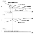
【図4】ハイブリッド車両の制御装置のタイムチャートを示し、(a)はエンジン回転速度のタイムチャート、(b)はトルクのタイムチャート、(c)は燃料カットのタイムチャートである。
【図5】基本回生トルク算出用テーブルである。
【図6】ロックアップ線図である。
【符号の説明】
2 エンジン
4 電動発電機(単に「モータ」ともいう)
6 トルクコンバータ
8 自動変速機
10 差動機
14 駆動輪
16 インバータ
18 バッテリ
20 インジェクタ
22 制御手段
24 車速センサ
26 エンジン回転センサ
28 タービン回転センサ
30 スロットルセンサ
32 ブレーキスイッチ
34 シフト位置スイッチ
36 ロックアップソレノイド(「ロックアップSOL」とも記載する)
38 シフトソレノイド(「シフトSOL」とも記載する)
40 ISCバルブ(「アイドル・スピード・コントロール バルブ」ともいう)
42 回生発電制御手段
44 燃料カット制御手段[0001]
TECHNICAL FIELD OF THE INVENTION
The present invention relates to a control device for a hybrid vehicle, that is, a regenerative power generation control device for a hybrid vehicle that regenerates kinetic energy of the vehicle by operating the motor as a generator during deceleration by an electric motor connected to a crankshaft of an engine, and in particular, relates to a lock device. The present invention relates to a control apparatus for a hybrid vehicle that controls regenerative torque in a system combined with an automatic transmission having a torque converter having an up mechanism.
[0002]
[Prior art]
Vehicles include a so-called hybrid vehicle equipped with an engine and a motor generator as power sources. A hybrid vehicle is provided with a motor generator having drive and assist functions directly connected to an engine mounted thereon, and controls the drive and assist state of the motor generator based on the operation state of the hybrid vehicle and the operation state of the engine. Control device. In a conventional hybrid vehicle control device, a hybrid vehicle provided with another motor generator (also referred to as a “motor”) other than an engine for the purpose of improving fuel efficiency has been proposed (see Patent Document 1).
[0003]
[Patent Document 1]
Japanese Patent No. 3350465 (pages 1-7, FIGS. 1-3)
[Patent Document 2]
JP-A-8-317506 (page 2-4, FIG. 1-4)
[0004]
[Problems to be solved by the invention]
Conventionally, the amount of regenerative power generated by a motor is determined based on the engine speed (also referred to as "engine speed"), and the amount of regenerative power is reduced as the engine speed decreases. The power generation amount is set to 0 (zero).
[0005]
By having such a configuration, when the fuel supply is restarted by the fuel supply amount control means, the engine return torque is not impaired by the regenerative braking torque, and the engine stall can be reliably prevented. On the other hand, there is no fear that the engine will stop, and the traveling comfort can be ensured.
[0006]
Further, as the engine speed approaches the return speed from a predetermined threshold (threshold) value, the amount of power generation is made to gradually approach zero, so that when the fuel supply is restarted by the fuel supply amount control means, the amount of power generation suddenly decreases. By stopping the deceleration regeneration, it is possible to avoid an unexpected shock in the traveling direction from acting on the occupant, thereby realizing a good running feeling.
[0007]
However, even after returning from the fuel cut, since the amount of power generation is determined based on the engine speed, the state where the amount of power generation is reduced to prevent engine stall is maintained, and after returning from the fuel cut, However, there is a problem in that the power generation amount is reduced more than necessary, and the power that should be recovered cannot be recovered.
[0008]
In particular, when an automatic transmission with a torque converter is mounted, in order to prevent engine stall due to an increase in creep torque load, a larger idle air amount is set in the drive range than in the non-drive range so that the engine output torque is increased. Further, during coasting, dragging from the wheel side unnecessarily increases the engine rotation speed higher than idling, and thus has the disadvantage that the above-mentioned problems become more remarkable.
[0009]
[Means for Solving the Problems]
Accordingly, the present invention provides a hybrid vehicle control device including an engine and a motor generator capable of driving and assisting the engine in order to eliminate the above-described disadvantages. Regenerative power generation control means for controlling, and fuel cut control means for performing fuel cut when a set fuel cut execution condition is satisfied, wherein the amount of regenerative power generated by the regenerative power generation means is set in advance to a value corresponding to the engine speed. It is characterized in that a control means is provided for controlling so as to be set to different values at the same engine speed when the fuel cut control is performed and when the fuel cut is not performed.
[0010]
BEST MODE FOR CARRYING OUT THE INVENTION
According to the invention described above, the characteristic of the regenerative power generation amount with respect to the engine speed is divided into a time when the fuel cut is performed and a time when the fuel cut is not performed, and the regenerative power generation amount is more than necessary to prevent the engine stall. In particular, when the fuel cut is not performed, the amount of regenerative power generation is increased, so that the storage battery can be charged more and the fuel consumption is reduced.
[0011]
【Example】
Hereinafter, embodiments of the present invention will be described in detail with reference to the drawings.
[0012]
1 to 6 show an embodiment of the present invention. In FIG. 2, reference numeral 2 denotes an engine mounted on a hybrid vehicle (not shown), for example.
[0013]
A motor generator (also referred to simply as “motor”) 4 is directly connected to an engine 2 mounted on a hybrid vehicle (not shown), and a lock-up mechanism (not shown) is provided on the motor generator 4. The
[0014]
At this time, the motor generator 4 has a motor function capable of driving the engine 2 and assisting the engine during traveling, and a power generation function.
[0015]
The
[0016]
Further, a
[0017]
A
[0018]
Further, the inverter 16 and the
[0019]
Furthermore, on the output side of the control means 22, a lock-up solenoid (also described as "lock-up SOL") 36 and a shift solenoid (also described as "shift SOL") 38 which constitute a part of the lock-up mechanism are provided. , An ISC valve (also referred to as an “idle speed control valve”) 40.
[0020]
The control means 22 includes a regenerative power generation control means 42 for controlling a regenerative power generation amount generated by the motor generator 4 and a fuel cut control for performing a fuel cut when a set fuel cut execution condition is satisfied. Means 44, the amount of regenerative power generated by the regenerative power generation means 42 is preset to a value corresponding to the engine speed, and the same engine speed is used when fuel cut control is performed and when fuel cut is not performed. Has a configuration for controlling so as to be set to different values.
[0021]
More specifically, the amount of regenerative power generated by the motor generator 4 when the fuel cut by the fuel cut
[0022]
Further, when returning from the fuel cut control by the fuel cut control means 44, the regenerative power generation amount is set so as to be gradually increased to a value at the time when the fuel cut is not performed.
[0023]
Furthermore, the amount of regenerative power generated by the motor generator 4 is set to decrease as the engine speed decreases, and the engine speed almost reaches the target idle speed in a case where the fuel cut is not performed. It is set so that it becomes zero when it is done.
[0024]
That is, the amount of regenerative power generated by the motor generator 4 is determined so that the engine speed (also referred to as “engine speed”) decreases, and the regenerative power generation is determined by whether or not the fuel cut is performed by the
[0025]
Further, when returning from the fuel cut by the fuel cut control means 44, the power generation amount is gradually increased to the regenerative power generation amount when the fuel cut is not executed, and the engine torque immediately after the fuel cut recovery is sufficiently recovered. In this state, the load caused by regenerative power generation is not sharply increased in a state where the engine is not running, thereby avoiding engine stall.
[0026]
Further, the regenerative power generation amount when the fuel cut is not performed is set to be zero near the target idle speed (also referred to as “target idle speed”), and the engine speed is reduced by dragging from the wheels due to coasting. Power generation is performed only when the number is high, the kinetic energy of the vehicle is effectively used for power generation, and an adverse effect on learning control of the idle speed of the engine is avoided.
[0027]
The fact that the learning control of the engine idling speed is not adversely affected means that the regenerative power generation amount must be set to zero in the target idling speed range to adversely affect the ISC learning control. In other words, although the regenerative power generation area could be expanded more than before, it must be zero in this regenerative power generation area.
[0028]
The control flow of the control means 22 will be described with reference to FIG.
[0029]
First, a fuel cut execution determination step A is performed based on the engine rotation speed from the engine rotation sensor 26 on the input side of the torque converter 6 and the throttle opening from the
[0030]
Then, after the fuel cut return transition determination step B and the basic regenerative torque calculation step C, the process proceeds to a regenerative torque calculation step D, in which a torque command value to the inverter 16 is calculated.
[0031]
Next, the operation will be described with reference to the control flowchart of the hybrid vehicle control device of FIG.
[0032]
When the control program of the control device of the hybrid vehicle starts (102), signals from various sensor groups such as the engine rotation sensor 26 and various switch groups such as the
[0033]
Then, it is determined whether or not the throttle opening from the
[0034]
Further, it is determined whether or not the above-mentioned throttle opening is less than the fuel cut determination threshold (threshold) (106) and whether or not the engine speed exceeds the fuel cut determination threshold (threshold). If (108) is NO, the flow shifts to fuel supply (112).
[0035]
After the execution of the fuel cut (110), the basic regenerative torque at the time of fuel cut is calculated using the basic regenerative torque calculation table shown in FIG. 5 (114), and the calculated basic regenerative torque at the time of fuel cut is calculated. The regenerative torque is set (116), and the flow shifts to the control program return (126).
[0036]
Further, after the above-described fuel supply is performed (112), the basic regenerative torque at the time of fuel supply is calculated using the basic regenerative torque calculation table shown in FIG. 5 (118). The process proceeds to the determination (120) of whether or not it is.
[0037]
If the determination (120) is YES, the regenerative torque is set so as to gradually increase to the basic regenerative torque at the time of fuel supply (122), and the process proceeds to the control program return (126). If the answer is NO, the basic regenerative torque at the time of fuel supply is set to the regenerative torque (124), and the routine shifts to the return (126) of the control program.
[0038]
Thus, the characteristic of the regenerative power generation amount with respect to the engine speed is divided into a time when the fuel cut is executed by the fuel cut control means 44 and a time when the fuel cut is not executed, so that it is necessary to prevent the engine stall. As described above, there is no need to reduce the amount of regenerative power generation, and when the fuel cut is not being performed, the regenerative power generation amount can be increased by the regenerative power
[0039]
The regenerative power generated by the motor generator 4 is set to a larger value when the fuel cut is not performed by the
[0040]
Further, when returning from the fuel cut control, the regenerative power generation amount is set to be gradually increased so as to be a value at the time when the fuel cut is not performed. This value is gradually increased to a value when the fuel cut is not performed, and the occurrence of engine stall can be prevented, which is practically advantageous.
[0041]
Furthermore, the amount of regenerative power generated by the motor generator 4 is set to decrease as the engine speed decreases, and when the engine speed does not execute the fuel cut by the fuel cut control means 44. Is set to be zero when the target idle speed is almost reached, regenerative power generation is performed until the vehicle reaches near the target idle speed, and the engine speed due to dragging from the wheels during coasting The regenerative power generation can be performed even when the vehicle rises, so that the kinetic energy of the vehicle can be effectively used.
[0042]
Note that the present invention is not limited to the above-described embodiment, and various application modifications are possible.
[0043]
【The invention's effect】
As described in detail above, according to the present invention, in a control device for a hybrid vehicle including an engine and a motor generator capable of driving and assisting the engine, the amount of regenerative power generated by the motor generator is controlled. Regenerative power generation control means, and fuel cut control means for performing fuel cut when the set fuel cut execution condition is satisfied, wherein the amount of regenerative power generated by the regenerative power generation means is preset to a value corresponding to the engine speed, In addition, when the fuel cut control is performed and when the fuel cut is not performed, the control means for controlling the engine speed to be set to different values at the same engine speed is provided. Is divided into the time when fuel cut is executed and the time when fuel cut is not executed. It is not necessary to reduce the amount of regenerative power generation, and when the fuel cut by the fuel cut control unit is not being performed, the regenerative power generation amount can be increased by the regenerative power generation control unit in particular. In addition, it is possible to reduce fuel consumption.
[Brief description of the drawings]
FIG. 1 is a control flowchart of a control device for a hybrid vehicle according to an embodiment of the present invention.
FIG. 2 is a schematic configuration diagram of a control device for a hybrid vehicle.
FIG. 3 is a control block diagram of a control unit.
FIG. 4 is a time chart of the control device of the hybrid vehicle, wherein (a) is a time chart of the engine rotation speed, (b) is a time chart of the torque, and (c) is a time chart of the fuel cut.
FIG. 5 is a table for calculating a basic regenerative torque.
FIG. 6 is a lock-up diagram.
[Explanation of symbols]
2 Engine 4 Motor generator (also simply called “motor”)
6
38 shift solenoid (also referred to as "shift SOL")
40 ISC valve (also called "idle speed control valve")
42 regenerative power generation control means 44 fuel cut control means
Claims (4)
Priority Applications (3)
| Application Number | Priority Date | Filing Date | Title |
|---|---|---|---|
| JP2003012129A JP4026133B2 (en) | 2003-01-21 | 2003-01-21 | Control device for hybrid vehicle |
| DE102004002701A DE102004002701B4 (en) | 2003-01-21 | 2004-01-19 | Control for a hybrid vehicle |
| US10/760,839 US7231284B2 (en) | 2003-01-21 | 2004-01-20 | Controller for hybrid vehicle |
Applications Claiming Priority (1)
| Application Number | Priority Date | Filing Date | Title |
|---|---|---|---|
| JP2003012129A JP4026133B2 (en) | 2003-01-21 | 2003-01-21 | Control device for hybrid vehicle |
Publications (2)
| Publication Number | Publication Date |
|---|---|
| JP2004229373A true JP2004229373A (en) | 2004-08-12 |
| JP4026133B2 JP4026133B2 (en) | 2007-12-26 |
Family
ID=32732777
Family Applications (1)
| Application Number | Title | Priority Date | Filing Date |
|---|---|---|---|
| JP2003012129A Expired - Fee Related JP4026133B2 (en) | 2003-01-21 | 2003-01-21 | Control device for hybrid vehicle |
Country Status (3)
| Country | Link |
|---|---|
| US (1) | US7231284B2 (en) |
| JP (1) | JP4026133B2 (en) |
| DE (1) | DE102004002701B4 (en) |
Cited By (9)
| Publication number | Priority date | Publication date | Assignee | Title |
|---|---|---|---|---|
| JP2007055475A (en) * | 2005-08-25 | 2007-03-08 | Toyota Motor Corp | Power output device, automobile mounted with same, and control method of power output device |
| WO2007086213A1 (en) * | 2006-01-27 | 2007-08-02 | Toyota Jidosha Kabushiki Kaisha | Vehicle and its control method |
| JP2008189241A (en) * | 2007-02-07 | 2008-08-21 | Toyota Motor Corp | Control device of power transmission apparatus |
| JP2009023496A (en) * | 2007-07-19 | 2009-02-05 | Hino Motors Ltd | Regenerative control device and hybrid car |
| JP2009143526A (en) * | 2007-12-13 | 2009-07-02 | Hyundai Motor Co Ltd | Method for limiting motor torque of hybrid vehicle |
| KR100916435B1 (en) | 2007-12-17 | 2009-09-07 | 현대자동차주식회사 | Control system of alternator for vehicle |
| JP2015110918A (en) * | 2013-12-06 | 2015-06-18 | いすゞ自動車株式会社 | Vehicle charging method, vehicle charging system, and vehicle |
| JP2019205310A (en) * | 2018-05-25 | 2019-11-28 | スズキ株式会社 | Dynamo-electric generator control arrangement |
| JPWO2019031277A1 (en) * | 2017-08-07 | 2020-08-13 | ジヤトコ株式会社 | Vehicle control device and control method |
Families Citing this family (8)
| Publication number | Priority date | Publication date | Assignee | Title |
|---|---|---|---|---|
| JP3701660B2 (en) * | 2003-07-04 | 2005-10-05 | 本田技研工業株式会社 | Control device for hybrid vehicle |
| US7406370B2 (en) * | 2004-08-24 | 2008-07-29 | Honeywell International Inc. | Electrical energy management system on a more electric vehicle |
| US7559387B2 (en) * | 2004-12-20 | 2009-07-14 | Gm Global Technology Operations, Inc. | Deceleration rate based engine spin control and engine off functionality |
| JP4810942B2 (en) * | 2005-09-20 | 2011-11-09 | トヨタ自動車株式会社 | Automatic stop device for internal combustion engine |
| DE112012006208T5 (en) * | 2012-04-09 | 2014-12-31 | Mitsubishi Electric Corporation | Vehicle power generator apparatus and vehicle power generation control method |
| JP2014118079A (en) * | 2012-12-18 | 2014-06-30 | Mitsubishi Motors Corp | Charge control unit for hybrid vehicle |
| JP5829652B2 (en) * | 2013-07-02 | 2015-12-09 | 本田技研工業株式会社 | Vehicle power supply |
| CN104442799B (en) * | 2013-09-18 | 2017-10-27 | 华创车电技术中心股份有限公司 | The method that prevention for non-idling flameout pattern is cut the engine |
Family Cites Families (24)
| Publication number | Priority date | Publication date | Assignee | Title |
|---|---|---|---|---|
| US3756204A (en) * | 1969-06-16 | 1973-09-04 | Hitachi Ltd | Fuel injection system for internal combustion engines |
| US3893434A (en) * | 1972-09-29 | 1975-07-08 | Arthur K Thatcher | Computer controlled sonic fuel system |
| US4021677A (en) * | 1975-03-03 | 1977-05-03 | Petro-Electric Motors, Ltd. | Hybrid power system |
| JPS5773259A (en) * | 1980-09-24 | 1982-05-07 | Aisin Seiki Co Ltd | Safety circuit of automatic speed changer control system |
| JPS59117950A (en) * | 1982-12-25 | 1984-07-07 | Aisin Seiki Co Ltd | Lockup controller |
| EP0533426B1 (en) * | 1991-09-20 | 1996-12-04 | Toyota Jidosha Kabushiki Kaisha | Fluid coupling power transmission with lockup clutch |
| US5670830A (en) * | 1994-04-28 | 1997-09-23 | Mitsubishi Jidosha Kogyo Kabushiki Kaisha | Fuel use limiter-equipped hybrid electric car |
| JP3371413B2 (en) | 1995-05-18 | 2003-01-27 | 株式会社エクォス・リサーチ | Hybrid vehicle |
| JP2002516055A (en) * | 1995-08-31 | 2002-05-28 | イーエスアーデー・エレクトロニク・ジステームス・ゲーエムベーハー・ウント・コンパニ・カーゲー | Towing control system and method for motor vehicle using electric machine |
| JP3454036B2 (en) * | 1995-11-13 | 2003-10-06 | トヨタ自動車株式会社 | Hybrid drive |
| US5982045A (en) * | 1996-04-19 | 1999-11-09 | Toyota Jidosha Kabushiki Kaisha | Hybrid vehicle drive system adapted to prevent concurrent mode change and transmission shifting or torque distribution ratio change |
| JP3861321B2 (en) * | 1996-05-02 | 2006-12-20 | トヨタ自動車株式会社 | Hybrid car |
| US5949146A (en) * | 1997-07-02 | 1999-09-07 | Cummins Engine Company, Inc. | Control technique for a lean burning engine system |
| US6209672B1 (en) * | 1998-09-14 | 2001-04-03 | Paice Corporation | Hybrid vehicle |
| JP3945045B2 (en) * | 1998-10-22 | 2007-07-18 | トヨタ自動車株式会社 | Regenerative braking torque control device |
| JP3350465B2 (en) * | 1998-12-18 | 2002-11-25 | 本田技研工業株式会社 | Hybrid vehicle control device |
| US6364807B1 (en) * | 2000-06-30 | 2002-04-02 | Ford Global Technologies, Inc. | Control strategy for a hybrid powertrain for an automotive vehicle |
| JP3976225B2 (en) * | 2000-11-10 | 2007-09-12 | 本田技研工業株式会社 | Control device for front and rear wheel drive vehicle |
| US6543565B1 (en) * | 2000-11-10 | 2003-04-08 | Ford Motor Company | Method and system for collecting regenerative braking energy in a parallel hybrid electric vehicle |
| JP3546408B2 (en) * | 2000-11-13 | 2004-07-28 | 本田技研工業株式会社 | Control device for front and rear wheel drive vehicles |
| JP3772683B2 (en) * | 2001-03-21 | 2006-05-10 | スズキ株式会社 | Control device for hybrid vehicle |
| JP4260377B2 (en) * | 2001-04-04 | 2009-04-30 | 本田技研工業株式会社 | Control device for hybrid vehicle |
| US6616569B2 (en) * | 2001-06-04 | 2003-09-09 | General Motors Corporation | Torque control system for a hybrid vehicle with an automatic transmission |
| US7131933B2 (en) * | 2001-12-07 | 2006-11-07 | Toyota Jidosha Kabushiki Kaisha | Vehicle control apparatus having means for changing inertia torque of engine during shifting action or during switching of operating state of lock-up clutch |
-
2003
- 2003-01-21 JP JP2003012129A patent/JP4026133B2/en not_active Expired - Fee Related
-
2004
- 2004-01-19 DE DE102004002701A patent/DE102004002701B4/en not_active Expired - Fee Related
- 2004-01-20 US US10/760,839 patent/US7231284B2/en active Active
Cited By (12)
| Publication number | Priority date | Publication date | Assignee | Title |
|---|---|---|---|---|
| JP2007055475A (en) * | 2005-08-25 | 2007-03-08 | Toyota Motor Corp | Power output device, automobile mounted with same, and control method of power output device |
| WO2007086213A1 (en) * | 2006-01-27 | 2007-08-02 | Toyota Jidosha Kabushiki Kaisha | Vehicle and its control method |
| US8108089B2 (en) | 2006-01-27 | 2012-01-31 | Toyota Jidosha Kabushiki Kaisha | Vehicle and control method thereof |
| JP2008189241A (en) * | 2007-02-07 | 2008-08-21 | Toyota Motor Corp | Control device of power transmission apparatus |
| US7854680B2 (en) | 2007-02-07 | 2010-12-21 | Toyota Jidosha Kabushiki Kaisha | Control device and control method for power train |
| JP2009023496A (en) * | 2007-07-19 | 2009-02-05 | Hino Motors Ltd | Regenerative control device and hybrid car |
| JP2009143526A (en) * | 2007-12-13 | 2009-07-02 | Hyundai Motor Co Ltd | Method for limiting motor torque of hybrid vehicle |
| KR100916435B1 (en) | 2007-12-17 | 2009-09-07 | 현대자동차주식회사 | Control system of alternator for vehicle |
| JP2015110918A (en) * | 2013-12-06 | 2015-06-18 | いすゞ自動車株式会社 | Vehicle charging method, vehicle charging system, and vehicle |
| JPWO2019031277A1 (en) * | 2017-08-07 | 2020-08-13 | ジヤトコ株式会社 | Vehicle control device and control method |
| JP2019205310A (en) * | 2018-05-25 | 2019-11-28 | スズキ株式会社 | Dynamo-electric generator control arrangement |
| JP7119575B2 (en) | 2018-05-25 | 2022-08-17 | スズキ株式会社 | generator controller |
Also Published As
| Publication number | Publication date |
|---|---|
| JP4026133B2 (en) | 2007-12-26 |
| US20040148071A1 (en) | 2004-07-29 |
| DE102004002701A1 (en) | 2004-08-19 |
| DE102004002701B4 (en) | 2012-11-08 |
| US7231284B2 (en) | 2007-06-12 |
Similar Documents
| Publication | Publication Date | Title |
|---|---|---|
| JP4127310B2 (en) | Vehicle control device, control method, program for realizing the method, and recording medium recording the program | |
| JP3715158B2 (en) | Engine stop / start control device | |
| JP4026133B2 (en) | Control device for hybrid vehicle | |
| JP4935268B2 (en) | Vehicle control device | |
| JP4260385B2 (en) | Control device for hybrid vehicle | |
| JP2011239605A (en) | Controller of vehicle | |
| JPWO2012104903A1 (en) | Regenerative control device, regenerative control method, and hybrid vehicle | |
| JP6852802B2 (en) | Hybrid vehicle control method and control device | |
| JP2004224110A (en) | Regeneration power generation control device for hybrid vehicle | |
| KR20090038943A (en) | Control method for fuel consumption improvement of hybrid electric vehicles | |
| JP5239841B2 (en) | Control device for hybrid vehicle | |
| JP2008092683A (en) | Drive torque controller for vehicle | |
| JP4237132B2 (en) | Automatic engine stop device for vehicle | |
| JP2008094238A (en) | Controller for hybrid car | |
| US6334499B1 (en) | Output control apparatus for hybrid vehicles | |
| JP2003061205A (en) | Motor controller for electric vehicle | |
| JP2020104668A (en) | Vehicular control apparatus | |
| JP3287943B2 (en) | Control device for hybrid vehicle | |
| JP3972905B2 (en) | Control device for hybrid vehicle | |
| JP3807024B2 (en) | Control device for compound drive system for vehicle | |
| JP3794351B2 (en) | Vehicle torque control device and torque control method | |
| JP3948022B2 (en) | Vehicle control apparatus and control method | |
| JP3861850B2 (en) | Control device for hybrid vehicle | |
| JP2004270512A (en) | Hybrid vehicle controller | |
| JP3988334B2 (en) | Control device for internal combustion engine |
Legal Events
| Date | Code | Title | Description |
|---|---|---|---|
| A621 | Written request for application examination |
Free format text: JAPANESE INTERMEDIATE CODE: A621 Effective date: 20051215 |
|
| A131 | Notification of reasons for refusal |
Free format text: JAPANESE INTERMEDIATE CODE: A131 Effective date: 20060616 |
|
| A521 | Request for written amendment filed |
Free format text: JAPANESE INTERMEDIATE CODE: A523 Effective date: 20060802 |
|
| A131 | Notification of reasons for refusal |
Free format text: JAPANESE INTERMEDIATE CODE: A131 Effective date: 20070227 |
|
| A521 | Request for written amendment filed |
Free format text: JAPANESE INTERMEDIATE CODE: A523 Effective date: 20070329 |
|
| TRDD | Decision of grant or rejection written | ||
| A01 | Written decision to grant a patent or to grant a registration (utility model) |
Free format text: JAPANESE INTERMEDIATE CODE: A01 Effective date: 20070914 |
|
| A61 | First payment of annual fees (during grant procedure) |
Free format text: JAPANESE INTERMEDIATE CODE: A61 Effective date: 20070927 |
|
| FPAY | Renewal fee payment (event date is renewal date of database) |
Free format text: PAYMENT UNTIL: 20101019 Year of fee payment: 3 |
|
| R151 | Written notification of patent or utility model registration |
Ref document number: 4026133 Country of ref document: JP Free format text: JAPANESE INTERMEDIATE CODE: R151 |
|
| FPAY | Renewal fee payment (event date is renewal date of database) |
Free format text: PAYMENT UNTIL: 20101019 Year of fee payment: 3 |
|
| FPAY | Renewal fee payment (event date is renewal date of database) |
Free format text: PAYMENT UNTIL: 20101019 Year of fee payment: 3 |
|
| FPAY | Renewal fee payment (event date is renewal date of database) |
Free format text: PAYMENT UNTIL: 20111019 Year of fee payment: 4 |
|
| FPAY | Renewal fee payment (event date is renewal date of database) |
Free format text: PAYMENT UNTIL: 20121019 Year of fee payment: 5 |
|
| FPAY | Renewal fee payment (event date is renewal date of database) |
Free format text: PAYMENT UNTIL: 20121019 Year of fee payment: 5 |
|
| FPAY | Renewal fee payment (event date is renewal date of database) |
Free format text: PAYMENT UNTIL: 20131019 Year of fee payment: 6 |
|
| LAPS | Cancellation because of no payment of annual fees |