JP2004223627A - Insert and knife edge replacement type rotating tool - Google Patents
Insert and knife edge replacement type rotating tool Download PDFInfo
- Publication number
- JP2004223627A JP2004223627A JP2003011713A JP2003011713A JP2004223627A JP 2004223627 A JP2004223627 A JP 2004223627A JP 2003011713 A JP2003011713 A JP 2003011713A JP 2003011713 A JP2003011713 A JP 2003011713A JP 2004223627 A JP2004223627 A JP 2004223627A
- Authority
- JP
- Japan
- Prior art keywords
- insert
- cutting edge
- cutting
- inscribed circle
- cutting blade
- Prior art date
- Legal status (The legal status is an assumption and is not a legal conclusion. Google has not performed a legal analysis and makes no representation as to the accuracy of the status listed.)
- Pending
Links
Images


Abstract
Description
【0001】
【発明が属する技術分野】
本発明は、正面フライス等の刃先交換式回転工具に用いられるインサート、特に、高硬度材の加工に適するインサート及び刃先交換式回転工具に関する。
【0002】
【従来の技術】
高硬度の被削材を正面フライスを使用して高送り加工する場合には、インサートの各切刃にかかる切削抵抗が増大するために、切刃が欠損し易くなってインサートが短寿命になるという不具合がある。そこで、これらの問題点を対策し、高送り加工における加工能率を改善した刃先交換式正面フライス工具が、例えば、下記の非特許文献1に提案されている。
【非特許文献1】ツールエンジニア(Vol.43、No.5、頁42−45、2002)
非特許文献1記載の正面フライス工具は、仕上げ面粗さが切削条件を適正化し、例えば、1刃当りの送り量を従来並みの量にすることや、或いは基体材種にサーメット材を用いるなどの配慮によって良好な仕上げ面粗さが得られることが記載されている。また、そのインサートは、図10、図11より、切刃稜線をなす4辺が夫々外側に凸の円弧状であり、逃げ面の略中央に平坦部が設けられ、該平坦部は切れ刃稜線から後退した位置よりインサート底面まで設けられ、該平坦部がインサートを工具本体に拘束する時の拘束面となっている。また、主切刃の切込み角は35度以下となっている。
【0003】
【発明が解決しようとする課題】
非特許文献1に記載のインサートを用いて切削加工を行うと、
1)インサートを工具本体の取付座に装着した時に、インサートを工具本体に拘束する拘束面が短く、高精度な位置決めが難しいという課題がある。
2)主切刃の切込み角が35度以下であるため、切込み深さを大きく設定できないという課題がある。
3)インサート自体の形状が特殊であるため、工具本体も特殊形状となり、従来の正面フライス工具本体に装着できない、等の課題がある。
【0004】
近年、工具径が160mm程度の正面フライスが広く使用されており、このような正面フライスを用いて、高硬度材を高送りで切削加工しても欠損が発生しないようなインサートが望まれている。本発明の目的は、高硬度材を高能率に切削加工し、非特許文献1記載のインサートよりも主切刃が長く、これによってインサートを工具本体に拘束する拘束面も長くすることにより、高精度な位置決めが可能となり、インサートの拘束力を高めたことにより、加工面の良好な加工面粗さが得られ、しかも従来の正面フライス工具が使用できるインサートを提供することにある。
【0005】
【課題を解決するための手段】
本発明は、正多角形板状のインサートにおいて、切刃は、直線状の主切刃、該主切刃に繋がる円弧状の面取りコーナー刃及び該面取りコーナー刃に繋がる直線状の副切刃、とから構成され、正面視で、該主切刃は該インサートの内接円に接し、該内接円の中心を通る直線が該副切刃と直角に交わる交点をP1、該直線が該内接円の中心Oに対して該交点P1と対向する側で該内接円と交わる交点をP2とし、該交点P1とP2間の距離をbとしたとき、1≦b/a≦1.1、該円弧状の面取りコーナー刃の半径Rが1.6mm≦R≦3.5mm及び該主切刃の逃げ角が11度≦G≦30度、としたことを特徴とするインサートであり、上記インサートを用い刃先交換式回転工具に装着したとき、該工具の切込み角αが40度≦α≦60度であることを特徴とする刃先交換式回転工具である。
【0006】
【発明の実施の形態】
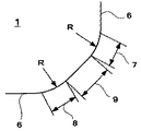
本発明の実施の形態を図1〜図3に基いて説明する。図1より、本発明のインサート1は、正面視で多角形板状をなし、底面2、底面2と対向する上面3、底面2と上面3との間には側面4が形成された平板状をなしている。上面3と側面4が交わる稜線部には切刃5が形成されている。尚、底面2はフライス工具本体の取付座にインサート1を装着するときの着座面になり、上面3はすくい面となり、側面4は逃げ面となり、角度Gの逃げ角が設けられている。図1より、主切刃6は、中心Oに対して対向する側の切刃5上にも形成され、隣どうしの主切刃6はその向きが直交するように形成されている。更に、これら4つの主切刃6は、正面視で仮想の内接円10に接するように構成され、主切刃6、面取りコーナ刃7、副切刃9、面取りコーナ刃8は、それぞれ内接円10の中心Oに対して、対称となるように切刃5上に形成される。図1より、正面視で内接円10の直径をa、内接円10の中心Oを通る直線Lが副切刃9と直角に交わる交点をP1、この直線Lが内接円10の中心Oに対して交点P1と対向する側においてこの内接円10と交わる交点をP2とし、これら交点P1と交点P2間の距離をbとしたとき、1≦b/a≦1.1であり、1≦b/a≦1.1に限定した理由は、b/aが1未満になると、直線状の主切刃が存在しなくなり、b/aが1.1を超えて大きくなると、直線状の副切刃の長さが短くなって、この副切刃により良好な仕上げ面粗さを有する加工面が得られなくなるからである。
【0007】
次に、面取りコーナ刃7、8は、図3より、本発明インサート1は、主切刃6と副切刃9との間に、それぞれ円弧状の面取りコーナ刃7、8を形成し、該円弧状の面取りコーナ刃7、8は、半径Rの円弧から構成され、主切刃6、面取りコーナ刃7、副切刃9、面取りコーナ刃8の順に滑らかに繋がれている。円弧状の面取りコーナ刃7、8の半径Rを、1.6≦R≦3.5mmに設けることにより、高硬度材でも高送りの切削加工が可能なインサートとなる。円弧状の面取りコーナ刃の半径Rを、1.6mm≦R≦3.5mmに限定した理由は、円弧状の面取りコーナ刃は切削加工時に被削材への食付き作用を行うが、半径Rが1.6mm未満となると、この面取りコーナ刃に切削抵抗負荷が集中してその強度が低下し、チッピングや欠損が発生し易くなり、半径が3.5mmを超えて大きくなると、面取りコーナ刃の強度は向上するが切削抵抗が増大してビビリ振動が発生し易くなり、主切刃は短くなるので、正面フライス工具本体の取付座にインサートを装着したときの拘束長さが小さくなり、インサートの固定が不安定になるので、面取りコーナ刃の半径Rは、1.6mm≦R≦3.5mmとなる円弧状の形状とした。
【0008】
更に、主切刃6の逃げ角Gを11度≦G≦30度に限定した理由は、Gが11度未満では、主切刃の強度は向上するが、逆に切削抵抗が高くなって切れ味が悪く、Gが30度を超えると、主切刃の強度が低下し、構造用鋼や合金工具鋼等からなる鉄系被削材の切削加工には適さないインサートになるからである。
【0009】
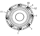
本発明のインサート1を刃先交換式回転工具正面本体に装着するときには、図4、図5の正面フライス11のインサート取付座12に取付け、主切刃6の1つがインサート取付座12の側壁に拘束されるように位置決めした後、止めねじ、或いはクランプ具13等を用いて正面フライス11に装着し、固定する。装着されたとき、インサート1の副切刃9の1つが工具本体11の先端部に位置する。上記正面フライスを用いて切削加工を行うと、主切刃6と面取りコーナ刃7は、加工機の主軸方向に対して一定の切込み量分の被削材を切削除去する切刃としての作用を行い、副切刃9は被削材の加工面粗さを向上させる。本発明インサート1は、従来例の円弧状切刃に相当する面取りコーナ刃の長さを短くすることができるので、面取りコーナ刃の耐欠損性を向上させることができる。上記刃先交換式回転工具の切込み角αを40度≦α≦60度とした理由は、Z軸方向にかかる切削抵抗が高くなるのを防ぎ、主切刃を直線状とすることによって拘束面を長くすることにより、高精度な位置決めが可能となり、インサートの拘束力を高めることができ、加工面の良好な面粗さが得られる。
【0010】
【実施例】
(実施例1)
JIS−K10相当材の超硬合金製から成る基体にPVD被膜を被覆した本発明例1、従来例2のインサートを製作した。表1にそのサイズを示す。
【0011】
【表1】

図4に示す、工具径160mm、8枚刃の正面フライス工具に装着して、HRC55の高硬度材であるSKD11からなる被削材を切削加工して切刃の摩耗状態及びチッピングの発生状況について試験した。切削諸元は、切削速度:70m/分、軸方向切込み深さ(Ad):1mm、半径方向切込み幅(Rd):130mm、1刃当たりの送り量(fz):0.15mm/刃、である。その結果を図7に示す。図7は、被削材の切削加工長さとインサートの主切刃の逃げ面最大摩耗幅(VBmax)との関係を示している。図7より、本発明例1は、切削長さが5mに達しても、逃げ面の最大摩耗幅は0.06mmであり継続して切削加工が可能であった。従来例2は、切削長さが5mに達した時、逃げ面にチッピングが発生し、最大摩耗幅は0.12mmであった。チッピングが発生した理由は、インサートの拘束力が十分でないために、インサートが振動して、切削抵抗の部分的な集中によりチッピングが発生したものと考えられる。
【0013】
(実施例2)
円弧状の面取りコーナ刃の半径Rを変えた本発明例4、5、6と比較例3、7の超硬合金製インサートを製作した。表1にそのサイズを併記する。上記インサートを図4に示す正面フライス工具に装着し、HRC55からなるSKD11の被削材について、fz:0.15mm/刃、で切削加工を行い、加工機のZ軸方向にかかる切削抵抗値を測定した。尚、Z軸方向にかかる切削抵抗値は、マシニングセンターのテーブルに多分力測定器を取付けて測定した。切削諸元は、切削速度:70m/分、軸方向切込み深さ(Ad):1mm、半径方向切込み幅(Rd):90mm、である。その結果を図8に示す。図8より、fzを一定の0.15mm/刃として切削加工を行った場合、円弧状の面取りコーナ刃の半径Rが大きくなるに従い、Z軸方向の切削抵抗値は大きくなるが、面取りコーナ刃にはチッピング、欠損等は発生しなかった。このことは、円弧状の面取りコーナ刃の半径Rを大きく設定すれば、fzを上げることが可能になること、即ち、面取りコーナ刃の強度が高くなることを示している。しかし、面取りコーナ刃の半径Rの値を大きくし過ぎると、Z軸方向の切削抵抗が高くなり過ぎ、ビビリ振動が発生する。従って、高硬度材を高送りで切削加工するためのインサートとして、主切刃と副切刃との間に形成する面取りコーナ刃の半径Rは、適切な範囲値を設定することが可能であることが判明した。
【0014】
続いて、上記本発明例4、5、6と比較例3、7のインサートを用いて切削試験を行った。fzを0.1mm〜0.25mmに変化させ、HRC55のSKD11材の切削加工を行った時に、円弧状の面取り刃のチッピング、欠損の発生状況について観察した。こ切削諸元は、切削速度:70m/分、軸方向切込み深さ(Ad):1mm、半径方向切込み幅(Rd):130mm、である。その結果を図9に示す。図9より、比較例3は、fzを0.13mmに上げると面取りコーナ刃に欠損が発生した。本発明例4〜6は、fzを0.15mmより大きくして加工を行ってもチッピングや欠損が発生せず、fzを0.22mm/刃としてもチッピングや欠損は発生しなかった。比較例7は、fzが0.17mm/刃を越えるとビビリ振動の発生が確認された。本発明例4〜6の面取りコーナ刃の半径Rを1.6mm〜3.5mmに設定したインサートを装着すれば、HRC55程度の高硬度材でも、fzを0.15mm〜0.22mmの高送りでフライス加工できることが確認できた。
【0015】
本発明のインサートは、図1に示す形状の他に、切刃5の稜線部に沿ってすくい面3にブレーカ溝を設けた形状としてもよい。ブレーカ溝を設けると、ブレーカ溝は切削加工により発生した切屑を分断又はカールさせて、切屑がすくい面と接触する衝撃力を緩和させることができるので、一層、高硬度材を高送りで切削加工を行うことができるようになる。次に、図2に示す側面図において、切刃5を底面2方向に凹円弧状の形状としたインサートにしてもよい。このように、切刃5を底面2方向に凹円弧状の形状にすると、切削加工時に切刃5が被削材に滑らかに当たるので、主切刃6、面取りコーナ刃7、8に欠損が発生することを防止することができる。また、正面視でインサートの中央部に、回転工具本体の取付座に装着・固定するためのねじ孔を有するインサートとしてもよい。
【0016】
【発明の効果】
本発明を適用することにより、インサートの取り付け精度が向上し、工具寿命も長くすることが可能になる。これにより、高硬度材を高送りで切削加工するのに適した刃先交換式回転工具用のインサートを提供することができる。また、本発明のインサートは、従来の正面フライス工具をそのまま使用することもできる。
【図面の簡単な説明】
【図1】図1は、本発明例の正面図を示す。
【図2】図2は、図1の側面図を示す。
【図3】図3は、図1のA部における切刃の構成を示す。
【図4】図4は、本発明例の正面フライスの正面図を示す。
【図5】図5は、図4の側面の断面図を示す。
【図6】図6は、被削材を切削加工しているときの状態を示す。
【図7】図7は、切削長さと逃げ面最大摩耗量との関係を示す。
【図8】図8は、面取りコーナ刃の半径RとZ軸方向の切削抵抗値との関係を示す。
【図9】図9は、切刃の欠損の発生状態を説明するための図を示す。
【図10】図10は、従来例のインサートの正面図を示す。
【図11】図11は、図10のAの矢視方向の側面図を示す。
【符号の説明】
1:インサート
2:底面
3:上面
4:側面
5:切刃
6:主切刃
7、8:面取りコーナ刃
9:副切刃
10:内接円
11:刃先交換式回転工具
12:取付座
13:クランプ具
α:切込み角[0001]
TECHNICAL FIELD OF THE INVENTION
TECHNICAL FIELD The present invention relates to an insert used for a cutting tool such as a face mill, and more particularly to an insert and a cutting tool that are suitable for machining a hard material.
[0002]
[Prior art]
When a high-hardness work material is subjected to high feed machining using a face mill, the cutting resistance applied to each cutting edge of the insert increases, so that the cutting edge is easily broken and the insert has a short life. There is a problem. Therefore, a non-interchangeable face milling tool that addresses these problems and improves machining efficiency in high feed machining has been proposed in, for example, Non-Patent
[Non-Patent Document 1] Tool Engineer (Vol. 43, No. 5, pp. 42-45, 2002)
In the face milling tool described in
[0003]
[Problems to be solved by the invention]
When cutting is performed using the insert described in Non-Patent
1) When the insert is mounted on the mounting seat of the tool body, there is a problem that the restraining surface for restraining the insert to the tool body is short, and it is difficult to perform high-precision positioning.
2) Since the cutting angle of the main cutting edge is 35 degrees or less, there is a problem that the cutting depth cannot be set large.
3) Since the shape of the insert itself is special, the tool body also has a special shape, and there is a problem that it cannot be mounted on a conventional face milling tool body.
[0004]
In recent years, face mills having a tool diameter of about 160 mm have been widely used, and inserts that do not cause chipping even when cutting high-hardness materials at high feed rates using such face mills are desired. . An object of the present invention is to cut a high-hardness material with high efficiency, to have a longer main cutting edge than the insert described in Non-Patent
[0005]
[Means for Solving the Problems]
In the present invention, in a regular polygonal plate-shaped insert, the cutting edge is a linear main cutting edge, an arc-shaped chamfered corner blade connected to the main cutting edge, and a linear sub-cutting edge connected to the chamfered corner blade, When viewed from the front, the main cutting edge is in contact with the inscribed circle of the insert, and an intersection point where a straight line passing through the center of the inscribed circle intersects the sub-cutting edge at right angles is P1, and the straight line is the inner cutting edge. Assuming that an intersection that intersects the inscribed circle on the side opposite to the intersection P1 with respect to the center O of the tangent circle is P2, and that the distance between the intersections P1 and P2 is b, 1 ≦ b / a ≦ 1.1 A radius R of the arc-shaped chamfered corner blade is 1.6 mm ≦ R ≦ 3.5 mm, and a clearance angle of the main cutting edge is 11 degrees ≦ G ≦ 30 degrees. When installed on a rotary tool with a replaceable cutting edge using an insert, the cutting angle α of the tool is 40 degrees ≦ α ≦ 60 degrees This is a rotary tool with a replaceable cutting edge.
[0006]
BEST MODE FOR CARRYING OUT THE INVENTION
An embodiment of the present invention will be described with reference to FIGS. 1, the
[0007]
Next, as shown in FIG. 3, the
[0008]
Further, the reason why the clearance angle G of the main cutting edge 6 is limited to 11 degrees ≦ G ≦ 30 degrees is that when G is less than 11 degrees, the strength of the main cutting edge is improved, but on the contrary, the cutting resistance is increased and the sharpness is sharpened. This is because if G exceeds 30 degrees, the strength of the main cutting edge decreases, and the insert becomes unsuitable for cutting iron-based work materials made of structural steel, alloy tool steel, and the like.
[0009]
When the
[0010]
【Example】
(Example 1)
Inserts of Example 1 of the present invention and Conventional Example 2 in which a substrate made of cemented carbide equivalent to JIS-K10 was coated with a PVD coating were manufactured. Table 1 shows the sizes.
[0011]
[Table 1]
Attached to a face milling tool with a tool diameter of 160 mm and 8 blades shown in FIG. 4, a work material made of SKD11 which is a hard material of HRC55 is machined, and a wear state of the cutting blade and a situation of occurrence of chipping are shown. Tested. The cutting specifications were as follows: cutting speed: 70 m / min, cutting depth in the axial direction (Ad): 1 mm, cutting width in the radial direction (Rd): 130 mm, feed amount per blade (fz): 0.15 mm / tooth. is there. FIG. 7 shows the result. FIG. 7 shows the relationship between the cutting length of the workpiece and the maximum flank wear width (VBmax) of the main cutting edge of the insert. As shown in FIG. 7, the maximum wear width of the flank was 0.06 mm in the inventive example 1 even when the cutting length reached 5 m, and cutting could be continued. In Conventional Example 2, when the cutting length reached 5 m, chipping occurred on the flank, and the maximum wear width was 0.12 mm. It is considered that the reason why chipping occurred was that the insert vibrated due to insufficient binding force of the insert and chipping occurred due to partial concentration of cutting resistance.
[0013]
(Example 2)
Cemented carbide inserts of Examples 4, 5, and 6 of the present invention and Comparative Examples 3 and 7 in which the radius R of the arc-shaped chamfered corner blade was changed were manufactured. Table 1 also shows the sizes. The above insert was mounted on the face milling tool shown in FIG. 4, and the work material of SKD11 made of HRC55 was subjected to cutting at fz: 0.15 mm / tooth, and the cutting resistance applied to the Z-axis direction of the working machine was calculated. It was measured. The cutting resistance value applied in the Z-axis direction was measured by attaching a force measuring device to a table of a machining center. The cutting specifications were as follows: cutting speed: 70 m / min, axial depth of cut (Ad): 1 mm, radial depth of cut (Rd): 90 mm. FIG. 8 shows the result. From FIG. 8, when cutting is performed with fz being a constant 0.15 mm / blade, as the radius R of the arc-shaped chamfered corner blade increases, the cutting resistance value in the Z-axis direction increases. No chipping, deficiency, etc. occurred. This indicates that if the radius R of the arc-shaped chamfered corner blade is set to be large, fz can be increased, that is, the strength of the chamfered corner blade increases. However, if the value of the radius R of the chamfered corner blade is too large, the cutting resistance in the Z-axis direction becomes too high, and chatter vibration occurs. Therefore, it is possible to set an appropriate range value for the radius R of the chamfered corner blade formed between the main cutting edge and the sub cutting edge as an insert for cutting a high-hardness material at a high feed rate. It has been found.
[0014]
Subsequently, cutting tests were performed using the inserts of Examples 4, 5, and 6 of the present invention and Comparative Examples 3 and 7. When fz was changed from 0.1 mm to 0.25 mm and the SKD11 material of HRC55 was cut, the occurrence of chipping and chipping of the arc-shaped chamfering blade was observed. The cutting specifications are as follows: cutting speed: 70 m / min, cutting depth in the axial direction (Ad): 1 mm, cutting width in the radial direction (Rd): 130 mm. The result is shown in FIG. From FIG. 9, in Comparative Example 3, when the fz was increased to 0.13 mm, the chamfered corner blade was damaged. In Inventive Examples 4 to 6, chipping and chipping did not occur even when processing was performed with fz larger than 0.15 mm, and chipping and chipping did not occur even when fz was set at 0.22 mm / blade. In Comparative Example 7, occurrence of chatter vibration was confirmed when fz exceeded 0.17 mm / blade. By mounting an insert in which the radius R of the chamfered corner blades of Examples 4 to 6 of the present invention is set to 1.6 mm to 3.5 mm, even with a high hardness material of about HRC55, fz is high feed of 0.15 mm to 0.22 mm. It was confirmed that milling was possible.
[0015]
The insert of the present invention may have a shape in which a breaker groove is provided on the
[0016]
【The invention's effect】
By applying the present invention, the mounting accuracy of the insert is improved, and the tool life can be extended. Thereby, it is possible to provide an insert for a cutting edge-changeable rotary tool suitable for cutting a high-hardness material at a high feed rate. Further, the insert of the present invention can use a conventional face milling tool as it is.
[Brief description of the drawings]
FIG. 1 shows a front view of an example of the present invention.
FIG. 2 shows a side view of FIG. 1;
FIG. 3 shows a configuration of a cutting blade in a portion A of FIG. 1;
FIG. 4 shows a front view of a face mill according to the present invention.
FIG. 5 shows a side sectional view of FIG. 4;
FIG. 6 shows a state when a work material is being cut.
FIG. 7 shows the relationship between the cutting length and the maximum flank wear amount.
FIG. 8 shows the relationship between the radius R of the chamfered corner blade and the cutting resistance value in the Z-axis direction.
FIG. 9 is a view for explaining a state in which a cutting edge is lost;
FIG. 10 shows a front view of a conventional insert.
FIG. 11 is a side view in the direction of the arrow A in FIG. 10;
[Explanation of symbols]
1: insert 2: bottom surface 3: top surface 4: side surface 5: cutting edge 6:
Claims (2)
Priority Applications (1)
| Application Number | Priority Date | Filing Date | Title |
|---|---|---|---|
| JP2003011713A JP2004223627A (en) | 2003-01-21 | 2003-01-21 | Insert and knife edge replacement type rotating tool |
Applications Claiming Priority (1)
| Application Number | Priority Date | Filing Date | Title |
|---|---|---|---|
| JP2003011713A JP2004223627A (en) | 2003-01-21 | 2003-01-21 | Insert and knife edge replacement type rotating tool |
Publications (1)
| Publication Number | Publication Date |
|---|---|
| JP2004223627A true JP2004223627A (en) | 2004-08-12 |
Family
ID=32900535
Family Applications (1)
| Application Number | Title | Priority Date | Filing Date |
|---|---|---|---|
| JP2003011713A Pending JP2004223627A (en) | 2003-01-21 | 2003-01-21 | Insert and knife edge replacement type rotating tool |
Country Status (1)
| Country | Link |
|---|---|
| JP (1) | JP2004223627A (en) |
Cited By (3)
| Publication number | Priority date | Publication date | Assignee | Title |
|---|---|---|---|---|
| CN103328143A (en) * | 2011-01-27 | 2013-09-25 | 特固克有限会社 | Tangential cutting insert |
| KR101549717B1 (en) | 2008-06-26 | 2015-09-02 | 쎄코 툴스 에이비 | A cutting insert with a wiper edge |
| CN107598245A (en) * | 2017-09-07 | 2018-01-19 | 中南大学 | Suitable for the milling cutter of high-speed cutting Precision Machining nickel-base alloy workpiece |
-
2003
- 2003-01-21 JP JP2003011713A patent/JP2004223627A/en active Pending
Cited By (7)
| Publication number | Priority date | Publication date | Assignee | Title |
|---|---|---|---|---|
| KR101549717B1 (en) | 2008-06-26 | 2015-09-02 | 쎄코 툴스 에이비 | A cutting insert with a wiper edge |
| CN103328143A (en) * | 2011-01-27 | 2013-09-25 | 特固克有限会社 | Tangential cutting insert |
| JP2014502927A (en) * | 2011-01-27 | 2014-02-06 | デグテック リミテッド | Tangential cutting insert |
| US9044813B2 (en) | 2011-01-27 | 2015-06-02 | Taegutec, Ltd. | Tangential cutting insert |
| CN103328143B (en) * | 2011-01-27 | 2015-07-29 | 特固克有限会社 | tangential cutting insert |
| KR101838238B1 (en) * | 2011-01-27 | 2018-03-13 | 대구텍 유한회사 | Tangential cutting insert |
| CN107598245A (en) * | 2017-09-07 | 2018-01-19 | 中南大学 | Suitable for the milling cutter of high-speed cutting Precision Machining nickel-base alloy workpiece |
Similar Documents
| Publication | Publication Date | Title |
|---|---|---|
| US8523498B2 (en) | Cutting insert and face milling cutter | |
| CN109641293B (en) | Cutting insert and indexable insert type rotary cutting tool | |
| WO2007142224A1 (en) | Cutting tool and cutting insert | |
| JP2004237438A (en) | Throw away tip and cutting tool | |
| JP2008018515A (en) | Cutting insert and cutting tool | |
| EP3378589B1 (en) | Replaceable-cutting-edge rotary cutting tool and insert | |
| JP2005111651A (en) | Tip, milling cutter, and machining method using the same | |
| JP2005040941A (en) | Milling cutter with tangentially mounted insert | |
| JP4879493B2 (en) | Ball nose end mill | |
| JP5301454B2 (en) | Chip type ball end mill chip material | |
| WO2017138170A1 (en) | Replaceable tool edge rotary cutting tool and insert | |
| CN109862983B (en) | Cutting insert and indexable insert type rotary cutting tool | |
| KR101959189B1 (en) | Cutting inserts and cutting blades | |
| JP2009119572A (en) | Insert and edge replaceable cutting tool | |
| JPH07299634A (en) | End mill | |
| JP4378307B2 (en) | Axial feed edge replaceable tool | |
| JP6086180B1 (en) | Replaceable blade cutting tool and insert | |
| JP2004223627A (en) | Insert and knife edge replacement type rotating tool | |
| JP6086179B1 (en) | Replaceable blade cutting tool and insert | |
| JP2008100316A (en) | Cutting tool, and finishing blade insert | |
| JPH09192930A (en) | Thread cutter | |
| JP4119967B2 (en) | Blade-replaceable rotary tool | |
| JP4142892B2 (en) | Blade-replaceable rotary tool | |
| JP2020116707A (en) | Blade edge replaceable end mill | |
| JPS5841060Y2 (en) | Throwaway tip |
Legal Events
| Date | Code | Title | Description |
|---|---|---|---|
| A977 | Report on retrieval |
Effective date: 20071115 Free format text: JAPANESE INTERMEDIATE CODE: A971007 |
|
| A131 | Notification of reasons for refusal |
Free format text: JAPANESE INTERMEDIATE CODE: A131 Effective date: 20071129 |
|
| A521 | Written amendment |
Free format text: JAPANESE INTERMEDIATE CODE: A523 Effective date: 20080123 |
|
| A521 | Written amendment |
Free format text: JAPANESE INTERMEDIATE CODE: A523 Effective date: 20080130 |
|
| A131 | Notification of reasons for refusal |
Effective date: 20080611 Free format text: JAPANESE INTERMEDIATE CODE: A131 |
|
| A521 | Written amendment |
Free format text: JAPANESE INTERMEDIATE CODE: A523 Effective date: 20080804 |
|
| A02 | Decision of refusal |
Free format text: JAPANESE INTERMEDIATE CODE: A02 Effective date: 20090312 |