JP2004219210A - Display device for vehicle - Google Patents
Display device for vehicle Download PDFInfo
- Publication number
- JP2004219210A JP2004219210A JP2003005923A JP2003005923A JP2004219210A JP 2004219210 A JP2004219210 A JP 2004219210A JP 2003005923 A JP2003005923 A JP 2003005923A JP 2003005923 A JP2003005923 A JP 2003005923A JP 2004219210 A JP2004219210 A JP 2004219210A
- Authority
- JP
- Japan
- Prior art keywords
- dial
- hand
- long
- short
- vehicle
- Prior art date
- Legal status (The legal status is an assumption and is not a legal conclusion. Google has not performed a legal analysis and makes no representation as to the accuracy of the status listed.)
- Granted
Links
- 239000003086 colorant Substances 0.000 claims description 11
- 238000010586 diagram Methods 0.000 description 12
- 230000000694 effects Effects 0.000 description 12
- 239000000758 substrate Substances 0.000 description 10
- 230000004048 modification Effects 0.000 description 5
- 238000012986 modification Methods 0.000 description 5
- 239000011347 resin Substances 0.000 description 5
- 229920005989 resin Polymers 0.000 description 5
- 230000003760 hair shine Effects 0.000 description 4
- 230000002093 peripheral effect Effects 0.000 description 3
- 239000004417 polycarbonate Substances 0.000 description 3
- 238000005452 bending Methods 0.000 description 2
- 230000005540 biological transmission Effects 0.000 description 2
- -1 for example Substances 0.000 description 1
- 239000000446 fuel Substances 0.000 description 1
- 230000003287 optical effect Effects 0.000 description 1
- 229920000515 polycarbonate Polymers 0.000 description 1
- 238000007920 subcutaneous administration Methods 0.000 description 1
Images


Landscapes
- Indicating Measured Values (AREA)
- Details Of Measuring Devices (AREA)
- Instrument Panels (AREA)
Abstract
Description
【0001】
【発明の属する技術分野】
本発明は、指針で文字盤上の表示意匠の指示を行うアナログ表示によって複数の情報を表示する車両用表示装置に関する。
【0002】
【従来の技術】
車両のインストルメントパネルには、スピードメータ、タコメータ、燃料計、温度計等の多数のアナログメータが配置されている。これらのアナログメータは、その構造上大型になり、インストルメントパネルのかなりのスペースを占めるので、これらのアナログメータのうちのいくつかはデジタルメータに置き換えることにより、占有スペースの縮小が図られている。
【0003】
また、これらのアナログメータをそれぞれ単眼メータとしてではなく、2個以上のアナログメータをコンビネーションメータとして一体化することで、複数の情報の表示ができると共に占有スペースの縮小を図ったものも存在する。
【0004】
【発明が解決しようとする課題】
しかしながら、上述のコンビネーションメータは、視認方向から見て横方向に配置されており、占有スペースの縮小効果があまり得られないものであった。
【0005】
そこで本発明は、上述した従来の問題点に鑑み、複数の情報の表示ができると共に、従来よりも占有スペースを縮小することができる車両用表示装置を提供することを目的としている。
【0006】
【課題を解決するための手段】
上記課題を解決するためになされた請求項1記載の発明は、それぞれ異なる車両関連情報に対応する第1および第2の表示意匠を含むアナログ表示領域を有する平板状の文字盤と、前記第1の表示意匠を指示する長指針と該長指針が取り付けられる第1の回転軸を有する長指針用ムーブメントとを含む第1の指針機構と、前記第2の表示意匠を指示する短長指針と該短指針が取り付けられる第2の回転軸を有する短指針用ムーブメントとを含む第2の指針機構とを備え、前記長指針用ムーブメントと前記短指針用ムーブメントは、前記第1の回転軸と前記第2の回転軸が一致するように配置されていることを特徴とする車両用表示装置に存する。
【0007】
請求項1記載の発明によれば、車両用表示装置は、それぞれ異なる車両関連情報に対応する第1および第2の表示意匠を含むアナログ表示領域を有する平板状の文字盤と、第1の表示意匠を指示する長指針と該長指針が取り付けられる第1の回転軸を有する長指針用ムーブメントとを含む第1の指針機構と、第2の表示意匠を指示する短長指針と該短指針が取り付けられる第2の回転軸を有する短指針用ムーブメントとを含む第2の指針機構とを備え、長指針用ムーブメントと短指針用ムーブメントは、第1の回転軸と第2の回転軸が一致するように配置されているので、従来よりも少ない占有スペースで、複数の情報を表示することができる。
【0008】
上記課題を解決するためになされた請求項2記載の発明は、前記文字盤は透明な部材で形成され、前記長指針は前記文字盤の一方の面に配置され、前記短指針は前記文字盤の他方の面に配置されていることを特徴とする請求項1記載の車両用表示装置に存する。
【0009】
請求項2記載の発明によれば、文字盤は透明な部材で形成され、長指針は文字盤の一方の面に配置され、短指針は文字盤の他方の面に配置されているので、1個の文字盤と長指針および短指針の2個の指針とによって従来よりも少ない占有スペースで、複数の情報を表示することができる。
【0010】
上記課題を解決するためになされた請求項3記載の発明は、前記長指針および前記短指針は前記文字盤の一方の面に配置されていることを特徴とする請求項1記載の車両用表示装置に存する。
【0011】
請求項3記載の発明によれば、長指針および短指針は文字盤の一方の面に配置されているので、従来よりも少ない占有スペースで、複数の情報を表示することができる。
【0012】
上記課題を解決するためになされた請求項4記載の発明は、前記長指針は、視認方向に対して前記短指針より手前に配置されると共に、その先端部が基部より折り曲げられて、前記短指針とほぼ同一の平面に位置していることを特徴とする請求項3記載の車両用表示装置に存する。
【0013】
請求項4記載の発明によれば、長指針は、視認方向に対して短指針より手前に配置されると共に、その先端部が基部より折り曲げられて、前記短指針とほぼ同一の平面に位置しているので、従来よりも少ない占有スペースで、複数の情報を表示することができる。
【0014】
上記課題を解決するためになされた請求項5記載の発明は、穴状または透明のシースルー領域と、所定の車両関連情報に対応する第1の表示意匠が形成されたアナログ表示領域とを有する円形平板状の長指針用文字盤と、前記第1の表示意匠で表される車両関連情報と異なる車両関連情報に対応する第2の表示意匠を含むアナログ表示領域を有し、前記シースルー領域を通して前記第2の表示意匠が視認可能な位置に配置された円形平板状の短指針用文字盤と、前記第1の表示意匠を指示する長指針と該長指針が取り付けられる第1の回転軸を有する長指針用ムーブメントとを含む長指針機構と、前記第2の表示意匠を指示する短長指針と該短指針が取り付けられる第2の回転軸を有する短指針用ムーブメントとを含む短指針機構とを備え、前記長指針用ムーブメントと前記短指針用ムーブメントは、前記第1の回転軸と前記第2の回転軸が一致するように配置されていることを特徴とする車両用表示装置に存する。
【0015】
請求項5記載の発明によれば、車両用表示装置は、穴状または透明のシースルー領域と、所定の車両関連情報に対応する第1の表示意匠が形成されたアナログ表示領域とを有する円形平板状の長指針用文字盤と、第1の表示意匠で表される車両関連情報と異なる車両関連情報に対応する第2の表示意匠を含むアナログ表示領域を有し、シースルー領域を通して第2の表示意匠が視認可能な位置に配置された円形平板状の短指針用文字盤と、第1の表示意匠を指示する長指針と該長指針が取り付けられる第1の回転軸を有する長指針用ムーブメントとを含む長指針機構と、第2の表示意匠を指示する短長指針と該短指針が取り付けられる第2の回転軸を有する短指針用ムーブメントとを含む短指針機構とを備え、長指針用ムーブメントと短指針用ムーブメントは、第1の回転軸と第2の回転軸が一致するように配置されているので、長指針用文字盤および短指針用文字盤の2個の文字盤と、長指針および短指針の2個の指針とによって従来よりも少ない占有スペースで、複数の情報を表示することができる。
【0016】
上記課題を解決するためになされた請求項6記載の発明は、前記短指針用文字盤は、視認方向から見た場合前記長指針用文字盤の背面側に配置されていることを特徴とする請求項5記載の車両用表示装置に存する。
【0017】
請求項6記載の発明によれば、短指針用文字盤は、視認方向から見た場合長指針用文字盤の背面側に配置されているので、長指針用文字盤の表示意匠と短指針用文字盤の表示意匠に前後感がでて、立体感を演出することができる。
【0018】
上記課題を解決するためになされた請求項7記載の発明は、前記短指針用文字盤は、視認方向から見た場合前記長指針用文字盤の前面側に配置されていることを特徴とする請求項5記載の車両用表示装置に存する。
【0019】
請求項7記載の発明によれば、短指針用文字盤は、視認方向から見た場合長指針用文字盤の前面側に配置されているので、長指針用文字盤の表示意匠と短指針用文字盤の表示意匠に前後感がでて、立体感を演出することができる。
【0020】
上記課題を解決するためになされた請求項8記載の発明は、前記長指針は、視認方向から見た場合前記長指針用文字盤の前面側に配置され、前記短指針は、前記長指針用文字盤の背面側に配置された前記短指針用文字盤の背面側に配置されていることを特徴とする請求項6記載の車両用表示装置に存する。
【0021】
請求項8記載の発明によれば、長指針は、視認方向から見た場合長指針用文字盤の前面側に配置され、短指針は、長指針用文字盤の背面側に配置された短指針用文字盤の背面側に配置されているので、従来よりも少ない占有スペースで、複数の情報を表示することができる。
【0022】
上記課題を解決するためになされた請求項9記載の発明は、前記長指針は、視認方向から見た場合前記長指針用文字盤の前面側に配置され、前記短指針は、前記長指針用文字盤と前記長指針用文字盤の背面側に配置された前記短指針用文字盤との間に配置されていることを特徴とする請求項6記載の車両用表示装置に存する。
【0023】
請求項9記載の発明によれば、長指針は、視認方向から見た場合長指針用文字盤の前面側に配置され、短指針は、長指針用文字盤と長指針用文字盤の背面側に配置された短指針用文字盤との間に配置されているので、従来よりも少ない占有スペースで、複数の情報を表示することができる。
【0024】
上記課題を解決するためになされた請求項10記載の発明は、前記短指針用文字盤のサイズおよび形状は、その上端および下端が、アイレンジの上端と前記長指針用文字盤の前記シースルー領域の開口部の上端を結ぶ線を延長した線と、前記アイレンジの下端と前記長指針用文字盤の前記シースルー領域の開口部の下端を結ぶ線を延長した線とで挟まれた範囲内に含まれると共に、その右端および左端が、右目アイレンジの右端と前記長指針用文字盤の前記シースルー領域の開口部の右端を結ぶ線を延長した線と、左目アイレンジの左端と前記長指針用文字盤のシースルー領域の開口部の左端を結ぶ線を延長した線とで挟まれた範囲内に含まれるように設定されることを特徴とする請求項6記載の車両用表示装置に存する。
【0025】
請求項10記載の発明によれば、短指針用文字盤のサイズおよび形状は、その上端および下端が、アイレンジの上端と長指針用文字盤のシースルー領域の開口部の上端を結ぶ線を延長した線と、アイレンジの下端と長指針用文字盤のシースルー領域の開口部の下端を結ぶ線を延長した線とで挟まれた範囲内に含まれると共に、その右端および左端が、右目アイレンジの右端と長指針用文字盤のシースルー領域の開口部の右端を結ぶ線を延長した線と、左目アイレンジの左端と長指針用文字盤のシースルー領域の開口部の左端を結ぶ線を延長した線とで挟まれた範囲内に含まれるように設定されるので、短指針用文字盤が、長指針用文字盤のシースルー領域内で長指針用文字盤よりも沈んだように視認され、立体感を演出することができる。
【0026】
上記課題を解決するためになされた請求項11記載の発明は、前記短指針用文字盤のサイズおよび形状は、その上端および下端が、アイレンジの下端と前記長指針用文字盤21の前記シースルー領域の開口部の上端を結ぶ線と、前記アイレンジの上端と前記長指針用文字盤の前記シースルー領域の開口部の下端を結ぶ線とで挟まれた範囲内に含まれると共に、その右端および左端が、左目アイレンジの左端と前記長指針用文字盤の前記シースルー領域の開口部の右端を結ぶ線と、右目アイレンジの右端と前記長指針用文字盤のシースルー領域の開口部の左端を結ぶ線とで挟まれた範囲内に含まれるように設定されることを特徴とする請求項7記載の車両用表示装置に存する。
【0027】
請求項11記載の発明によれば、短指針用文字盤のサイズおよび形状は、その上端および下端が、アイレンジの下端と長指針用文字盤のシースルー領域の開口部の上端を結ぶ線と、アイレンジの上端と長指針用文字盤のシースルー領域の開口部の下端を結ぶ線とで挟まれた範囲内に含まれると共に、その右端および左端が、左目アイレンジの左端と長指針用文字盤のシースルー領域の開口部の右端を結ぶ線と、右目アイレンジの右端と長指針用文字盤のシースルー領域の開口部の左端を結ぶ線とで挟まれた範囲内に含まれるように設定されるので、短指針用文字盤が、長指針用文字盤のシースルー領域内で長指針用文字盤よりも浮かんだように視認され、立体感を演出することができる。
【0028】
上記課題を解決するためになされた請求項12記載の発明は、前記長指針が、視認方向から見て前記短指針の手前に配置された場合、前記長指針には、前記第2の表示意匠および前記短指針の視認が可能な範囲でその先端部を所定色で光輝させるためのホットスタンプ層が形成されることを特徴とする請求項1から11のいずれか1項に記載の車両用表示装置に存する。
【0029】
請求項12記載の発明によれば、長指針が、視認方向から見て短指針の手前に配置された場合、長指針には、第2の表示意匠および短指針の視認が可能な範囲でその先端部を所定色で光輝させるためのホットスタンプ層が形成されるので、長指針の後方にある短指針用文字盤のアナログ表示領域および短指針を前方からハッキリ視認することができるようになり、第2の情報を明確に知ることが可能になる。
【0030】
上記課題を解決するためになされた請求項13記載の発明は、前記長指針用文字盤と前記短指針用文字盤は、それぞれ異なる色を有することを特徴とする請求項5から12のいずれか1項に記載の車両用表示装置に存する。
【0031】
請求項13記載の発明によれば、長指針用文字盤と短指針用文字盤は、それぞれ異なる色を有するので、それぞれが指示する車両関連情報を識別するのが容易となる。
【0032】
上記課題を解決するためになされた請求項14記載の発明は、前記第1の表示意匠と前記第2の表示意匠は、それぞれ異なる色を有することを特徴とする請求項1から13のいずれか1項に記載の車両用表示装置に存する。
【0033】
請求項14記載の発明によれば、第1の表示意匠と第2の表示意匠は、それぞれ異なる色を有するので、それぞれが指示する車両関連情報を識別するのが容易となる。
【0034】
上記課題を解決するためになされた請求項15記載の発明は、前記長指針と前記短指針は、それぞれ異なる色を有することを特徴とする請求項1から14のいずれか1項に記載の車両用表示装置に存する。
【0035】
請求項15記載の発明によれば、長指針と短指針は、それぞれ異なる色を有するので、それぞれが指示する車両関連情報を識別するのが容易となる。
【0036】
【発明の実施の形態】
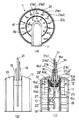
以下、本発明の実施の形態を図面に基づいて説明する。図1は、本発明による車両用表示装置の第1の実施形態を示し、(A)は正面図、(B)は側面図、(C)は断面図である。本車両用表示装置1は、指針で文字盤上の表示意匠の指示を行うアナログ表示によって複数の車両関連情報を表示する構成を備えたものである。
【0037】
本車両用表示装置1は、図1に示すように、リアカバー10、フロントカバー11、文字盤21、文字盤導光部23、長指針用ムーブメント12、長指針16、長指針用基板19、長指針用光源26、文字盤光源27、長指針用導光板29、短指針用ムーブメント12′、短指針16′、短指針用基板19′、短指針用光源26′および短指針用導光板29′を含んで構成される。
【0038】
文字盤21は、透明な樹脂たとえばPC(ポリカーボネイト)で円形の平板状に形成され、中心に開口部が形成され、開口部より外周側に第1および第2の車両関連情報表示用の第1および第2の表示意匠が形成されたアナログ表示領域21bを有する。第1の情報は、たとえば、車両の走行速度であり、第2の情報は、たとえば、車両のエンジンの回転数である。
【0039】
アナログ表示領域21bの表示意匠は、アナログ表示領域21bに形成された凹部にたとえば白色の着色剤を充填することにより形成された第1の表示意匠としての目盛り21b1および文字21b2と、第2の表示意匠としての情報用目盛り21b1′および文字21b2′を有する。
【0040】
文字盤21の目盛り21b1および文字21b2は、長指針16および長指針用ムーブメント12を含む長指針機構と共に、第1の車両関連情報として車両の走行速度を指示する第1のメータとしてのスピードメータを構成し、文字盤21の目盛り21b1′および文字21b2′は、短指針16′および短指針用ムーブメント12′を含む短指針機構と共に、第2の車両関連情報としてエンジンの回転数を指示する第2のメータとしてのタコメータを構成する。
【0041】
リアカバー10およびフロントカバー11は、たとえば樹脂製であり、文字盤21を固定すると共に、文字盤21の前面側に配置された長指針16および長指針用ムーブメント12を含む長指針機構と、文字盤21の背面側に配置された短指針16′および短指針用ムーブメント12′を含む短指針機構を収容している。リアカバー10は、文字盤21上の短指針16′の回動範囲外に対応した形状を有している。フロントカバー11は、文字盤21上の長指針16の回動範囲外に対応した形状を有している。すなわち、長指針16および短指針16′は、通常、最大270度程度しか回動することはないので、リアカバー10及びフロントカバー11は、この回動範囲外に位置するように、文字盤21の中心から下方に所定の幅を持って延長した形状を有している。
【0042】
長指針用ムーブメント12は、たとえばステッパーモータであり、長指針用基板19に固定され、第1の回転軸としてのその回転軸に取り付けられた長指針16に動力を伝達する。長指針16は、長指針用ムーブメント12を動力源として、文字盤21の前面側を回転軸を中心にして所定の回動範囲内で回動しつつ、アナログ表示領域21bに形成された第1の情報用目盛り21b1および文字21b2を指示する。なお、長指針用ムーブメント12の回転軸と長指針16の間に、平歯車等を含む動力伝達機構部(図示しない)を設けても良い。
【0043】
長指針16は、その基部16bがムーブメント12の回転軸に連結されている。基部16bは、下面が開口した略円筒形状の指針キャップ16aと一体化されている。長指針16は、導光性を有する先細りの透明樹脂製であり、その先端部16cの下面には先端部16cを所定色で光輝させるためのホットスタンプ層(図示しない)が形成されている。また、長指針16の基部16bには、長指針用基板19に配置された長指針用光源26からの光を長指針用導光板29を介して受光する受光面16dが形成されている。
【0044】
一方、短指針用ムーブメント12′は、たとえばステッパーモータであり、その回転軸が長指針用ムーブメント12′の回転軸と一致するように短指針用基板19′に固定され、第2の回転軸としてのその回転軸に取り付けられた短指針16′に動力を伝達する。短指針16′は、短指針用ムーブメント12′を動力源として、文字盤21の背面側を回転軸を中心にして所定の回動範囲内で回動しつつ、アナログ表示領域21bに形成された第2の情報用目盛り21b1′および文字21b2′を指示する。なお、短指針用ムーブメント12′の回転軸と短指針16′の間に、平歯車等を含む動力伝達機構部(図示しない)を設けても良い。
【0045】
短指針16′は、その基部16b′が短指針用ムーブメント12′の回転軸に連結されている。基部16b′は、下面が開口した略円筒形状の指針キャップ16a′と一体化されている。短指針16′は、導光性を有する先細りの透明樹脂製であり、その先端部16c′の下面には先端部16c′を所定色で光輝させるためのホットスタンプ層(図示しない)が形成されている。また、短指針16′の基部16b′には、短指針用基板19′に配置された短指針用光源26′からの光を短指針用導光板29′を介して受光する受光面16d′が形成されている。
【0046】
一方、短指針用基板19′には、たとえば、LED(発光ダイオード)からなる文字盤光源27が配置されており、この文字盤光源27からの光は、文字盤21と一体形成された文字盤導光部23を介して文字盤21のアナログ表示領域21bを照明する。
【0047】
このような構成において、文字盤21の前面側から車両用表示装置を見ると、長指針用光源26からの光を受けてホットスタンプ層の色に基づいて光輝し、文字盤21の前面側を回動する長指針16が、第1の情報用目盛り21b1および文字21b2を指示しているのが視認でき、それにより、第1のアナログ表示情報、すなわち車両の走行速度を知ることができる。
【0048】
同様に、短指針用光源26′からの光を受けてホットスタンプ層の色に基づいて光輝し、文字盤21の背面側を回動する短指針16′が、第2の情報用目盛り21b1′および文字21b2′を指示しているのが透明な文字盤21を通して視認でき、それにより第2のアナログ表示情報、すなわちエンジンの回転数を知ることができる。
【0049】
このように、本発明の第1の実施形態によれば、1個の文字盤21と文字盤の両面に配置された2個の指針すなわち長指針16および短指針16′によって、第1の情報(たとえば、車両の走行速度)を指示する第1のメータ(たとえば、スピードメータ)と、第2の情報(たとえば、エンジンの回転数)を指示する第2のメータ(たとえば、タコメータ)が、視認方向から見て前後方向に配置されているので、従来よりも少ない占有スペースで、複数(第1の実施形態では、2種類)の情報を表示することができる。
【0050】
なお、図1の車両用表示装置は、図1(C)の右側から見て、文字盤21の前面側に長指針16が視認されかつ文字盤21の背面側に文字盤21を通して短指針16′が視認される構成となっているが、これに代えて、図1(C)の左方向から、文字盤21の前面側に短指針16′が視認されかつ文字盤21の背面側に文字盤21を通して長指針16が視認されるような構成をとっても良い。
【0051】
次に、図2は、図1の車両用表示装置の変形例を示す断面図である。図2では、短指針16′は、文字盤21の前面側に配置され、長指針16は、その基部16bと先端部16cの中間を折り曲げることによって、短指針16′よりも視認方向から見てさらに手前に配置されている構成部分が異なり、その他の構成は図1と同じである。
【0052】
このように、第1の実施形態の変形例によれば、長指針16を屈曲させることで、長指針16および短指針16′の両方を文字盤21の一方の面、たとえば前面側にまとめてほぼ同一の平面に位置するように配置することができる。なお、この場合、文字盤21を透明な部材ではなく不透明な部材で形成しても良い。また、長指針16および短指針16′の両方を透明な文字盤21の背面側に配置しても良い。
【0053】
次に、図3は、本発明による車両用表示装置の第2の実施形態を示す断面図である。図3では、主として、文字盤21は長指針用文字盤として使用され、さらに短指針用文字盤21′が設けられている構成部分が異なり、その他の構成は、ほぼ図1と同じである。
【0054】
すなわち、本車両用表示装置は、リアカバー10、フロントカバー11、文字盤21、文字盤導光部23、長指針用ムーブメント12、長指針16、長指針用基板19、長指針用光源26、文字盤光源27、長指針用導光板29、短指針用文字盤21′、短指針用ムーブメント12′、短指針16′、短指針用基板19′、短指針用文字盤導光部23′、短指針用光源26′および短指針用導光板29′を含んで構成される。(以下、この第2の実施形態では、短指針用文字盤21′、短指針用文字盤導光部23′、と対比するために、文字盤21を長指針用文字盤21、文字盤導光部23を長指針用文字盤導光部23と記す。)
【0055】
長指針用文字盤光源27は、長指針用基板19に配置されており、この長指針用文字盤光源23からの光は、長指針用文字盤21と一体形成された長指針用文字盤導光部23を介して長指針用文字盤21のアナログ表示領域21bを照明する。
【0056】
一方、短指針用基板19′には、たとえば、LED(発光ダイオード)からなる短指針用文字盤光源27′が配置されており、この短指針用文字盤光源27′からの光は、短指針用文字盤21′と一体形成された短指針用文字盤導光部23′を介して短指針用文字盤21′のアナログ表示領域21b′を照明する。
【0057】
長指針用文字盤21は、図1の文字盤21のアナログ表示領域21bから第2の情報用目盛り21b1′および文字21b2′を削除して第1の情報用目盛り21b1および文字21b2のみを形成し、さらに、中心とアナログ表示領域21bの間に穴状または透明な円形のシースルー領域21aを有する。
【0058】
すなわち、シースルー領域21aは、長指針用文字盤21の中心から所定の半径を有する略円形状をしており、アナログ表示領域21bは、このシースルー領域21aを囲むような所定幅のリング状をしている。
【0059】
短指針用文字盤21′は、透明な部材(たとえば、PC樹脂)で円形の平板状に形成され、長指針用文字盤21の背面側に配置される。短指針用文字盤21′は、中心に開口部が形成され、開口部より外周側に、長指針用文字盤21のシースルー領域21a内に入るアナログ表示領域21b′を有する。このアナログ表示領域21bには、第2の情報用目盛り21b1′および文字21b2′が形成されている。
【0060】
このような構成において、長指針用文字盤21の前面側から車両用表示装置を見ると、長指針用光源26からの光を受けてホットスタンプ層の色に基づいて光輝し、長指針用文字盤21の前面側を回動する長指針16が、第1の情報用目盛り21b1および文字21b2を指示しているのが視認でき、それにより、第1のアナログ表示情報、すなわち車両の走行速度を知ることができる。
【0061】
同様に、短指針用光源26′からの光を受けてホットスタンプ層の色に基づいて光輝し、短指針用文字盤21′の背面側を回動する短指針16′が、第2の情報用目盛り21b1′および文字21b2′を指示しているのが透明な短指針用文字盤21′と長指針用文字盤21のシースルー領域21aとを通して視認でき、それにより第2のアナログ表示情報、すなわちエンジンの回転数を知ることができる。
【0062】
このように、本発明の第2の実施形態によれば、2個の文字盤、すなわち長指針用文字盤21および短指針用文字盤21′と、各文字盤にそれぞれ配置された長指針16および短指針16′とによって、第1の情報(たとえば、車両の走行速度)を指示する第1のメータ(たとえば、スピードメータ)と、第2の情報(たとえば、エンジンの回転数)を指示する第2のメータ(たとえば、タコメータ)が、視認方向から見て前後方向に配置されているので、従来よりも少ない占有スペースで、複数(第1の実施形態では、2種類)の情報を表示することができる。また、長指針用文字盤21の表示意匠と短指針用文字盤21′の表示意匠に前後感がでて、立体感を演出することができる。
【0063】
なお、図3の車両用表示装置は、図3の右側から見て、長指針用文字盤21の前面側に長指針16が視認されかつ短指針用文字盤21′の背面側に短指針16′が視認される構成となっているが、これに代えて、図3の左方向から、短指針用文字盤21′の前面側に短指針16′が視認されかつ長指針用文字盤21の背面側に長指針用文字盤21を通して長指針16が視認されるような構成をとっても良い。この場合、短指針用文字盤21′を透明な部材ではなく不透明な部材で形成しても良い。
【0064】
次に、図4は、図3の車両用表示装置の変形例を示す断面図である。図4では、短指針16′は、短指針用文字盤21′の前面側、すなわち長指針用文字盤21と短指針用文字盤21′の間に配置され、長指針16は、その基部16bと先端部16cの中間を折り曲げることによって、短指針16′より前方に配置されており、さらに、短指針用文字盤光源27′が短指針用光源も兼ねているという構成部分が異なり、その他の構成はほぼ図3と同じである。
【0065】
このように、第1の実施形態の変形例によれば、短指針16′を短指針用文字盤21′の前面側に配置することができる。なお、この場合、文字盤21を透明な部材ではなく不透明な部材で形成しても良い。
【0066】
また、図4の車両用表示装置は、図4の右側から見て、長指針用文字盤21の前面側に長指針16が視認されかつ短指針用文字盤21′の前面側に短指針16′が視認される構成となっているが、これに代えて、図4の皮下だ理法光から、短指針用文字盤21′の前面側に短指針16′が視認されかつ長指針用文字盤21の背面側に緒指針用文字盤21を通して長指針16が視認されるような構成をとっても良い。
【0067】
次に、図5は、図3の車両用表示装置における長指針用文字盤と短指針用文字盤の形状および配置関係の第1の例を説明する図であり、(A)は斜視図、(B)は正面図、(C)は側面図を示す。図5においては、円形平板状の長指針用文字盤21のシースルー領域21aが穴状に形成されている場合を示し、視認方向から見て、長指針用文字盤21が前方に配置され、円形平板状の短指針用文字盤21′は後方に配置される。また、短指針用文字盤21′の直径は、長指針用文字盤21のシースルー領域21a内に入る寸法とすることができる。
【0068】
次に、図6は、図3の車両用表示装置における長指針用文字盤と短指針用文字盤の形状および配置関係の第2の例を説明する図であり、(A)は斜視図、(B)は正面図、(C)は側面図を示す。図6においては、円形平板状の長指針用文字盤21のシースルー領域21aが穴状に形成されている場合を示し、視認方向から見て、円形平板状の短指針用文字盤21′が前方に配置され、長指針用文字盤21は後方に配置される。また、短指針用文字盤21′の直径は、長指針用文字盤21のシースルー領域21a内に入る寸法とすることができる。
【0069】
次に、図7は、図3の車両用表示装置における長指針用文字盤と短指針用文字盤の形状および配置関係の第3の例を説明する図であり、(A)は斜視図、(B)は正面図、(C)は側面図を示す。図7においては、円形平板状の長指針用文字盤21のシースルー領域21aが穴状ではなく、アナログ表示領域21bから連続して透明に形成されている場合を示し、視認方向から見て、長指針用文字盤21が前方に配置され、透明または不透明な部材で形成された円形平板状の短指針用文字盤21′は、後方に配置される。また、短指針用文字盤21′の直径は、長指針用文字盤21のシースルー領域21a内に入る寸法とすることができる。
【0070】
次に、図8は、図3の車両用表示装置における長指針用文字盤と短指針用文字盤の形状および配置関係の第4の例を説明する図であり、(A)は斜視図、(B)は正面図、(C)は側面図を示す。図8においては、円形平板状の長指針用文字盤21のシースルー領域21aが穴状ではなく、アナログ表示領域21bから連続して透明に形成されている場合を示し、視認方向から見て、透明または不透明な部材で形成された円形平板状の短指針用文字盤21′が前方に配置され、透明な長指針用文字盤21は後方に配置される。また、短指針用文字盤21′の直径は、長指針用文字盤21のシースルー領域21a内に入る寸法とすることができる。
【0071】
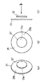
次に、図9は、図3の車両用表示装置における長指針用文字盤と短指針用文字盤の形状および配置とアイレンジとの関係の第1の例を説明する図であり、(A)および(B)は、それぞれ、車両用表示装置を横から見た場合および上から見た場合を示す。図9においては、円形平板状の長指針用文字盤21のシースルー領域21aが穴状に形成されていると共に、視認方向から見て、長指針用文字盤21が前方に配置され、円形平板状の短指針用文字盤21′は後方に配置されている場合を示す。
【0072】
このように、短指針用文字盤21′が長指針用文字盤21の後方に配置された場合、車両用表示装置を車室内のたとえばインストルメントパネルのメータフード(図示しない)の下部に配置し、ドライバのアイポイントEPから視認されるとき、短指針用文字盤21′のサイズおよび形状は、図9(A)に示すように、その上端および下端が、アイレンジERの上端と長指針用文字盤21のシースルー領域21aの開口部の上端を結ぶ線(ラインA)を延長した線と、アイレンジERの下端と長指針用文字盤21のシースルー領域21aの開口部の下端を結ぶ線(ラインB)を延長した線とで挟まれた範囲内に含まれると共に、図9(B)に示すように、その右端および左端が、右目アイレンジERR の右端と長指針用文字盤21のシースルー領域21aの開口部の右端を結ぶ線(ラインC)を延長した線と、左目アイレンジERL の左端と長指針用文字盤21のシースルー領域21aの開口部の左端を結ぶ線(ラインD)を延長した線とで挟まれた範囲内に含まれるように設定される。このように設定すると、短指針用文字盤21′が、長指針用文字盤21のシースルー領域21a内で長指針用文字盤21よりも沈んだように視認され、立体感を演出することができる。
【0073】
次に、図10は、図3の車両用表示装置における長指針用文字盤と短指針用文字盤の形状および配置とアイレンジとの関係の第2の例を説明する図であり、(A)および(B)は、それぞれ、車両用表示装置を横から見た場合および上から見た場合を示す。図10においては、円形平板状の長指針用文字盤21のシースルー領域21aが穴状に形成されていると共に、視認方向から見て、円形平板状の短指針用文字盤21′が前方に配置され、長指針用文字盤21は後方に配置されている場合を示す。
【0074】
このように、短指針用文字盤21′が長指針用文字盤21の前方に配置された場合、車両用表示装置を車室内のたとえばインストルメントパネルのメータフード(図示しない)の下部に配置し、ドライバのアイポイントEPから視認されるとき、短指針用文字盤21′のサイズおよび形状は、図10(A)に示すように、その上端および下端が、アイレンジERの下端と長指針用文字盤21のシースルー領域21aの開口部の上端を結ぶ線(ラインA)と、アイレンジERの上端と長指針用文字盤21のシースルー領域21aの開口部の下端を結ぶ線(ラインB)とで挟まれた範囲内に含まれると共に、図10(B)に示すように、その右端および左端が、左目アイレンジERL の左端と長指針用文字盤21のシースルー領域21aの開口部の右端を結ぶ線(ラインC)と、右目アイレンジERR の右端と長指針用文字盤21のシースルー領域21aの開口部の左端を結ぶ線(ラインD)とで挟まれた範囲内に含まれるように設定される。このように設定すると、短指針用文字盤21′が、長指針用文字盤21のシースルー領域21a内で長指針用文字盤21よりも浮かんだように視認され、立体感を演出することができる。
【0075】
次に、図11(A)および(B)は、長指針16と短指針16′の位置関係を示す図である。図11(A)に示すように、視認方向から見て、長指針16が短指針16′の前方に配置されている場合、長指針16には先端部16c′を所定色で光輝させるためのホットスタンプ層(図示しない)が形成されている。このホットスタンプ層が、長指針16の中間部16fの下面付近まで形成されていると、短指針用文字盤21′のアナログ表示領域21b′の第2の情報用目盛り21b1′および文字21b2′や、長指針16と重なった場合の短指針16′が、このホットスタンプ層で隠されてしまうため見にくくなるという現象が発生する。
【0076】
そこで、図11(B)に示すように、長指針16のホットスタンプ層は、短指針用文字盤21′のアナログ表示領域21b′の第2の情報用目盛り21b1′および文字21b2′や、長指針16と重なった場合の短指針16′と干渉する範囲(すなわち、上述の中間部16fを含む)には印刷せず、透明なままとすることにより、長指針16の後方にある短指針用文字盤21′のアナログ表示領域21b′および短指針16′を前方からハッキリ視認することができるようになり、第2の情報を明確に知ることが可能になる。
【0077】
以上の通り、本発明の実施の形態について説明したが、本発明はこれに限らず、種々の変形、応用が可能である。
【0078】
たとえば、表示すべき複数の情報に対して、情報毎に文字盤の色または表示意匠(すなわち、目盛りおよび文字)の色を異なる色とすることで、情報を識別がし易いように構成することができる。一例として、長指針用文字盤21はスピードメータ、短指針用文字盤21′はタコメータとして構成する場合、スピードメータの目盛りおよび文字を白色にし、タコメータの目盛りおよび文字を青色にすることができる。
【0079】
また、表示すべき複数の情報に対して、情報毎に長指針の色と短指針の色を異なる色とすることで、情報を識別がし易いように構成することができる。一例として、長指針用文字盤21はスピードメータ、短指針用文字盤21′はタコメータとして構成する場合、スピードメータの長指針を橙色に光輝させ、タコメータの短指針を赤色に光輝させることができる。
【0080】
また、長指針用文字盤は円形に限らず、他の形状としても良い。この場合は、短指針用文字盤は、その外周端が長指針用文字盤の目盛りや文字等にかからないサイズおよび形状に設定される。
【0081】
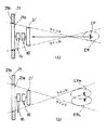
また、本発明は、第1および第2の情報は、車両の走行速度およびエンジンの回転数に限らず、他の情報としても良く、種々の情報を組み合わせることができる。たとえば、図12に示すベースとなるメータ1A(たとえば、スピードメータ+各種インジケータ、ウォーニング類)に、図13に示すオプションのタコメータ1Bを追加したい場合、メータ1Aの文字盤21の穴状または透明なシースルー領域21aにほぼ対応する文字盤21′を有するオプションのタコメータ1Bをベースのメータ1Aの文字盤21の前面に設置することで、図14に示すようにスピードメータとタコメータを一体化したメータ1Cを構成することができるので、文字盤や基板等の部品を新規に作成する必要無しに、オプション対応が可能となる。この場合、タコメータ1Bの文字盤21′は透明な部材または不透明な部材のどちらで形成されていても良い。また、タコメータ1Bをメータ1Aの背面側に配置することもできる。
【0082】
【発明の効果】
請求項1記載の発明によれば、従来よりも少ない占有スペースで、複数の情報を表示することができる。
【0083】
請求項2記載の発明によれば、1個の文字盤と長指針および短指針の2個の指針とによって従来よりも少ない占有スペースで、複数の情報を表示することができる。
【0084】
請求項3記載の発明によれば、従来よりも少ない占有スペースで、複数の情報を表示することができる。
【0085】
請求項4記載の発明によれば、従来よりも少ない占有スペースで、複数の情報を表示することができる。
【0086】
請求項5記載の発明によれば、長指針用文字盤および短指針用文字盤の2個の文字盤と、長指針および短指針の2個の指針とによって従来よりも少ない占有スペースで、複数の情報を表示することができる。
【0087】
請求項6記載の発明によれば、長指針用文字盤の表示意匠と短指針用文字盤の表示意匠に前後感がでて、立体感を演出することができる。
【0088】
請求項7記載の発明によれば、長指針用文字盤の表示意匠と短指針用文字盤の表示意匠に前後感がでて、立体感を演出することができる。
【0089】
請求項8記載の発明によれば、従来よりも少ない占有スペースで、複数の情報を表示することができる。
【0090】
請求項9記載の発明によれば、従来よりも少ない占有スペースで、複数の情報を表示することができる。
【0091】
請求項10記載の発明によれば、短指針用文字盤が、長指針用文字盤のシースルー領域内で長指針用文字盤よりも沈んだように視認され、立体感を演出することができる。
【0092】
請求項11記載の発明によれば、短指針用文字盤が、長指針用文字盤のシースルー領域内で長指針用文字盤よりも浮かんだように視認され、立体感を演出することができる。
【0093】
請求項12記載の発明によれば、長指針の後方にある短指針用文字盤のアナログ表示領域および短指針を前方からハッキリ視認することができるようになり、第2の情報を明確に知ることが可能になる。
【0094】
請求項13記載の発明によれば、それぞれが指示する車両関連情報を識別するのが容易となる。
【0095】
請求項14記載の発明によれば、それぞれが指示する車両関連情報を識別するのが容易となる。
【0096】
請求項15記載の発明によれば、それぞれが指示する車両関連情報を識別するのが容易となる。
【図面の簡単な説明】
【図1】本発明による車両用表示装置の第1の実施形態を示し、(A)は正面図、(B)は側面図、(C)は断面図である。
【図2】図1の車両用表示装置の変形例を示す断面図である。
【図3】本発明による車両用表示装置の第2の実施形態を示す断面図である。
【図4】図3の車両用表示装置の変形例を示す断面図である。
【図5】図3の車両用表示装置における長指針用文字盤と短指針用文字盤の形状および配置関係の第1の例を説明する図であり、(A)は斜視図、(B)は正面図、(C)は側面図を示す。
【図6】図3の車両用表示装置における長指針用文字盤と短指針用文字盤の形状および配置関係の第2の例を説明する図であり、(A)は斜視図、(B)は正面図、(C)は側面図を示す。
【図7】図3の車両用表示装置における長指針用文字盤と短指針用文字盤の形状および配置関係の第3の例を説明する図であり、(A)は斜視図、(B)は正面図、(C)は側面図を示す。
【図8】図3の車両用表示装置における長指針用文字盤と短指針用文字盤の形状および配置関係の第4の例を説明する図であり、(A)は斜視図、(B)は正面図、(C)は側面図を示す。
【図9】図3の車両用表示装置における長指針用文字盤と短指針用文字盤の形状および配置とアイレンジとの関係の第1の例を説明する図であり、(A)および(B)は、それぞれ、車両用表示装置を横から見た場合および上から見た場合を示す。
【図10】図3の車両用表示装置における長指針用文字盤と短指針用文字盤の形状および配置とアイレンジとの関係の第2の例を説明する図であり、(A)および(B)は、それぞれ、車両用表示装置を横から見た場合および上から見た場合を示す。
【図11】長指針と短指針の位置関係を示す図である。
【図12】本発明によるオプション対応におけるベースのメータを示し、(A)は正面図、(B)は断面図である。
【図13】本発明によるオプション対応におけるオプションのメータを示し、(A)は正面図、(B)は断面図である。
【図14】本発明によるオプション対応におけるベースのメータとオプションのメータを一体化したメータを示し、(A)は正面図、(B)は断面図である。
【符号の説明】
1 車両用表示装置
12 長指針用ムーブメント
12′ 短指針用ムーブメント
16 長指針
16b 基部
16c 先端部
16′ 短指針
21 文字盤(長指針用文字盤)
21a シースルー領域
21b アナログ表示領域
21′ 短指針用文字盤
21b′ アナログ表示領域
ER アイレンジ
ERR 右目アイレンジ
ERL 左目アイレンジ[0001]
TECHNICAL FIELD OF THE INVENTION
The present invention relates to a display device for a vehicle that displays a plurality of pieces of information by an analog display in which a display design on a dial is instructed by a pointer.
[0002]
[Prior art]
Many analog meters such as a speedometer, a tachometer, a fuel gauge, and a thermometer are arranged on an instrument panel of a vehicle. Since these analog meters are large in structure and occupy a considerable amount of space in the instrument panel, some of these analog meters have been replaced with digital meters to reduce the occupied space. .
[0003]
In addition, some of these analog meters are not monocular meters, but two or more analog meters are integrated as a combination meter to display a plurality of pieces of information and reduce the occupied space.
[0004]
[Problems to be solved by the invention]
However, the above-described combination meter is arranged in the horizontal direction when viewed from the viewing direction, and the effect of reducing the occupied space cannot be obtained much.
[0005]
Accordingly, an object of the present invention is to provide a vehicle display device capable of displaying a plurality of pieces of information and reducing an occupied space as compared with the related art, in view of the above-described conventional problems.
[0006]
[Means for Solving the Problems]
The invention according to
[0007]
According to the first aspect of the present invention, a vehicle display device includes: a flat dial having an analog display area including first and second display designs respectively corresponding to different vehicle-related information; A first pointer mechanism including a long pointer indicating a design and a movement for the long pointer having a first rotation axis to which the long pointer is attached; a short-long pointer indicating the second display design; A second pointer mechanism including a movement for a short hand having a second rotation axis attached thereto, wherein the movement for the long hand and the movement for the short hand have the first rotation axis and the second rotation axis coinciding with each other. With such arrangement, a plurality of pieces of information can be displayed with less occupied space than in the past.
[0008]
The invention according to claim 2, which has been made to solve the above problem, wherein the dial is formed of a transparent member, the long hand is disposed on one surface of the dial, and the short hand is provided on the dial. The vehicle display device according to
[0009]
According to the invention described in claim 2, the dial is formed of a transparent member, the long hand is arranged on one surface of the dial, and the short hand is arranged on the other surface of the dial. A plurality of pieces of information can be displayed with less occupied space than in the past by using two dials and two hands, a long hand and a short hand.
[0010]
The invention according to claim 3, which has been made to solve the above-mentioned problem, wherein the long hand and the short hand are arranged on one surface of the dial. Exists in the device.
[0011]
According to the third aspect of the present invention, since the long hand and the short hand are arranged on one surface of the dial, a plurality of pieces of information can be displayed with less occupied space than in the related art.
[0012]
The invention according to
[0013]
According to the invention as set forth in
[0014]
According to a fifth aspect of the present invention, there is provided a circular shape having a hole-shaped or transparent see-through area and an analog display area in which a first display design corresponding to predetermined vehicle-related information is formed. A flat long dial face, and an analog display area including a second display design corresponding to vehicle-related information different from the vehicle-related information represented by the first display design, and It has a circular flat plate-shaped short hand dial arranged at a position where the second display design can be viewed, a long hand pointing to the first display design, and a first rotation axis to which the long hand is attached. A long hand mechanism including a movement for a long hand, a short hand mechanism including a short hand for indicating the second display design, and a movement for a short hand having a second rotation axis to which the short hand is attached. Prepare, Serial length pointer for movement with the short pointer for movement, there is provided a display device for a vehicle, characterized in that said first rotary shaft and the second rotation axis is arranged to coincide.
[0015]
According to the invention described in claim 5, the vehicle display device is a circular flat plate having a hole-shaped or transparent see-through area and an analog display area in which a first display design corresponding to predetermined vehicle-related information is formed. Having a second display design including a second display design corresponding to vehicle-related information different from the vehicle-related information represented by the first display design, and a second display through the see-through region A circular flat plate-shaped dial for a short hand arranged at a position where a design can be visually recognized, a long hand for indicating a first display design, and a movement for a long hand having a first rotation axis to which the long hand is attached; And a short hand mechanism including a short hand indicating the second display design and a movement for the short hand having a second rotation axis to which the short hand is attached. And short guidelines Since the movement is arranged so that the first rotation axis and the second rotation axis coincide with each other, the two dials of the dial for the long hand and the dial for the short hand, and the dial for the long hand and the short hand are used. With the two pointers, a plurality of pieces of information can be displayed with less occupied space than before.
[0016]
The invention according to
[0017]
According to the invention as set forth in
[0018]
The invention according to claim 7, which has been made to solve the above problem, is characterized in that the short hand dial is disposed on the front side of the long hand dial when viewed from the viewing direction. A vehicle display device according to claim 5.
[0019]
According to the invention described in claim 7, since the dial for the short hand is disposed on the front side of the dial for the long hand when viewed from the viewing direction, the display design of the dial for the long hand and the hand for the short hand are displayed. The display design of the dial has a sense of front and back, and can produce a three-dimensional effect.
[0020]
The invention according to claim 8, which has been made to solve the above problem, wherein the long hand is disposed on the front side of the long hand dial when viewed from the viewing direction, and the short hand is provided for the long hand. 7. The vehicle display device according to
[0021]
According to the invention described in claim 8, the long hand is disposed on the front side of the long hand dial when viewed from the viewing direction, and the short hand is disposed on the rear side of the long hand dial. Since it is arranged on the back side of the dial, a plurality of information can be displayed with less occupied space than before.
[0022]
The invention according to claim 9, which has been made to solve the above problem, wherein the long hand is disposed on the front side of the dial for the long hand when viewed from the viewing direction, and the short hand is provided for the long hand. The vehicle display device according to
[0023]
According to the ninth aspect of the invention, the long hand is disposed on the front side of the long hand dial when viewed from the viewing direction, and the short hand is disposed on the rear side of the long hand dial and the long hand dial. , A plurality of pieces of information can be displayed with less occupied space than before.
[0024]
The invention according to
[0025]
According to the tenth aspect of the present invention, the size and shape of the short hand dial are such that the upper end and the lower end extend a line connecting the upper end of the eye range and the upper end of the opening of the see-through region of the long hand dial. Line between the lower end of the eye range and the line extending from the lower end of the see-through area opening of the dial for the long hand, and the right end and the left end are the right eye range. The line connecting the right end of the long dial and the right end of the see-through area opening of the long hand dial and the line connecting the left end of the left eye range and the left end of the see-through area opening of the long hand dial have been extended. Since it is set to be included in the range sandwiched between the line and the dial, the dial for the short hand is visually recognized as sinking below the dial for the long hand in the see-through area of the dial for the long hand, A feeling can be produced.
[0026]
The invention according to
[0027]
According to the invention described in
[0028]
The invention according to
[0029]
According to the invention as set forth in
[0030]
The invention according to claim 13 which has been made to solve the above-mentioned problem, wherein the dial for the long hand and the dial for the short hand have different colors, respectively. The vehicle display device according to
[0031]
According to the thirteenth aspect, the dial for the long hand and the dial for the short hand have different colors, so that it is easy to identify the vehicle-related information indicated by each.
[0032]
The invention according to claim 14, which has been made to solve the above-mentioned problem, is characterized in that the first display design and the second display design have different colors, respectively. The vehicle display device according to
[0033]
According to the invention described in claim 14, the first display design and the second display design have different colors, respectively, so that it is easy to identify the vehicle-related information specified by each.
[0034]
A vehicle according to any one of
[0035]
According to the fifteenth aspect, since the long hand and the short hand have different colors, it is easy to identify the vehicle-related information indicated by each.
[0036]
BEST MODE FOR CARRYING OUT THE INVENTION
Hereinafter, embodiments of the present invention will be described with reference to the drawings. 1A and 1B show a first embodiment of a vehicle display device according to the present invention, wherein FIG. 1A is a front view, FIG. 1B is a side view, and FIG. The
[0037]
As shown in FIG. 1, the
[0038]
[0039]
The display design of the
[0040]
The scale 21b1 and the characters 21b2 of the
[0041]
The
[0042]
The
[0043]
The base 16 b of the
[0044]
On the other hand, the
[0045]
The base 16b 'of the
[0046]
On the other hand, a
[0047]
In such a configuration, when the display device for a vehicle is viewed from the front side of the
[0048]
Similarly, the
[0049]
As described above, according to the first embodiment of the present invention, the first information is provided by one
[0050]
In the vehicle display device of FIG. 1, when viewed from the right side of FIG. 1C, the
[0051]
Next, FIG. 2 is a sectional view showing a modified example of the vehicle display device of FIG. In FIG. 2, the
[0052]
As described above, according to the modification of the first embodiment, by bending the
[0053]
Next, FIG. 3 is a sectional view showing a second embodiment of the vehicle display device according to the present invention. In FIG. 3, the
[0054]
That is, the display device for a vehicle includes a
[0055]
The long hand
[0056]
On the other hand, a short hand
[0057]
The
[0058]
That is, the see-through
[0059]
The
[0060]
In such a configuration, when the display device for a vehicle is viewed from the front side of the dial for
[0061]
Similarly, the
[0062]
As described above, according to the second embodiment of the present invention, two dials, that is, the
[0063]
In the vehicle display device shown in FIG. 3, the
[0064]
Next, FIG. 4 is a sectional view showing a modified example of the vehicle display device of FIG. In FIG. 4, the
[0065]
Thus, according to the modification of the first embodiment, the
[0066]
Further, in the vehicle display device shown in FIG. 4, when viewed from the right side of FIG. 4, the
[0067]
Next, FIG. 5 is a view for explaining a first example of the shape and arrangement of the long hand dial and the short hand dial in the vehicle display device of FIG. 3, (A) being a perspective view, (B) shows a front view, and (C) shows a side view. FIG. 5 shows a case where the see-through
[0068]
Next, FIG. 6 is a view for explaining a second example of the shape and arrangement relationship of the long hand dial and the short hand dial in the vehicle display device of FIG. 3, (A) is a perspective view, (B) shows a front view, and (C) shows a side view. FIG. 6 shows a case in which the see-through
[0069]
Next, FIG. 7 is a diagram illustrating a third example of the shape and arrangement of the long hand dial and the short hand dial in the vehicle display device of FIG. 3, (A) being a perspective view, (B) shows a front view, and (C) shows a side view. FIG. 7 shows a case in which the see-through
[0070]
Next, FIG. 8 is a diagram illustrating a fourth example of the shape and arrangement of the long hand dial and the short hand dial in the vehicle display device of FIG. 3, (A) being a perspective view, (B) shows a front view, and (C) shows a side view. FIG. 8 shows a case where the see-through
[0071]
Next, FIG. 9 is a diagram illustrating a first example of the relationship between the shape and arrangement of the dial for the long hand and the dial for the short hand and the eye range in the display device for a vehicle in FIG. ) And (B) show the case where the vehicle display device is viewed from the side and the case where it is viewed from above, respectively. In FIG. 9, the see-through
[0072]
As described above, when the
[0073]
Next, FIG. 10 is a diagram illustrating a second example of the relationship between the shapes and arrangements of the long hand dial and the short hand dial and the eye range in the vehicle display device of FIG. ) And (B) show the case where the vehicle display device is viewed from the side and the case where it is viewed from above, respectively. In FIG. 10, the see-through
[0074]
As described above, when the
[0075]
Next, FIGS. 11A and 11B are diagrams showing the positional relationship between the
[0076]
Therefore, as shown in FIG. 11 (B), the hot stamp layer of the
[0077]
As described above, the embodiment of the present invention has been described. However, the present invention is not limited to this, and various modifications and applications are possible.
[0078]
For example, for a plurality of pieces of information to be displayed, a color of a dial or a color of a display design (that is, a scale and a character) may be different for each piece of information so that the information can be easily identified. Can be. For example, when the
[0079]
In addition, for a plurality of pieces of information to be displayed, the color of the long hand and the color of the short hand are set to different colors for each information, so that the information can be easily identified. As an example, when the
[0080]
Further, the dial for the long hand is not limited to a circular shape, but may have another shape. In this case, the short hand dial is set to a size and shape such that the outer peripheral edge does not cover the scales, characters, etc. of the long hand dial.
[0081]
In the present invention, the first and second information are not limited to the traveling speed of the vehicle and the number of revolutions of the engine, and may be other information, and various information can be combined. For example, when it is desired to add an
[0082]
【The invention's effect】
According to the first aspect of the present invention, it is possible to display a plurality of pieces of information with less occupied space than before.
[0083]
According to the second aspect of the present invention, a plurality of pieces of information can be displayed using a single dial and two hands of a long hand and a short hand in a less occupied space than before.
[0084]
According to the third aspect of the present invention, it is possible to display a plurality of pieces of information with less occupied space than before.
[0085]
According to the fourth aspect of the present invention, it is possible to display a plurality of pieces of information with less occupied space than before.
[0086]
According to the invention described in claim 5, the two dials of the dial for the long hand and the dial for the short hand and the two hands of the long hand and the short hand make it possible to occupy a plurality of spaces in a less occupied space than before. Information can be displayed.
[0087]
According to the invention as set forth in
[0088]
According to the invention as set forth in claim 7, the display design of the dial for the long hand and the display design of the dial for the short hand can have a sense of front and rear, and can produce a three-dimensional effect.
[0089]
According to the invention of claim 8, a plurality of pieces of information can be displayed with less occupied space than before.
[0090]
According to the ninth aspect, a plurality of pieces of information can be displayed with less occupied space than in the related art.
[0091]
According to the tenth aspect of the invention, the dial for the short hand is visually recognized as if it sinks below the dial for the long hand in the see-through area of the dial for the long hand, and a three-dimensional effect can be produced.
[0092]
According to the eleventh aspect, the dial for the short hand is visually recognized as floating above the dial for the long hand in the see-through area of the dial for the long hand, and a three-dimensional effect can be produced.
[0093]
According to the twelfth aspect of the present invention, the analog display area of the dial for the short hand behind the long hand and the short hand can be clearly seen from the front, so that the second information can be clearly known. Becomes possible.
[0094]
According to the thirteenth aspect, it is easy to identify the vehicle-related information specified by each.
[0095]
According to the fourteenth aspect, it is easy to identify the vehicle-related information specified by each.
[0096]
According to the fifteenth aspect, it is easy to identify the vehicle-related information specified by each.
[Brief description of the drawings]
FIG. 1 shows a first embodiment of a vehicle display device according to the present invention, wherein (A) is a front view, (B) is a side view, and (C) is a cross-sectional view.
FIG. 2 is a sectional view showing a modification of the vehicle display device of FIG.
FIG. 3 is a cross-sectional view showing a second embodiment of the vehicle display device according to the present invention.
FIG. 4 is a sectional view showing a modification of the vehicle display device of FIG. 3;
5A and 5B are diagrams illustrating a first example of a shape and an arrangement relationship between a dial for a long hand and a dial for a short hand in the display device for a vehicle in FIG. 3, wherein FIG. 5A is a perspective view and FIG. Shows a front view, and (C) shows a side view.
6A and 6B are diagrams illustrating a second example of the shape and arrangement of the long hand dial and the short hand dial in the vehicle display device of FIG. 3; FIG. 6A is a perspective view, and FIG. Shows a front view, and (C) shows a side view.
7A and 7B are diagrams illustrating a third example of the shape and arrangement of the long hand dial and the short hand dial in the vehicle display device of FIG. 3; FIG. 7A is a perspective view, and FIG. Shows a front view, and (C) shows a side view.
8A and 8B are diagrams illustrating a fourth example of the shape and arrangement of the long hand dial and the short hand dial in the vehicle display device of FIG. 3, wherein FIG. 8A is a perspective view and FIG. Shows a front view, and (C) shows a side view.
9A and 9B are diagrams illustrating a first example of the relationship between the shape and arrangement of the long hand dial and the short hand dial in the vehicle display device of FIG. 3 and the eye range, and FIGS. B) shows a case where the vehicle display device is viewed from the side and a case where it is viewed from above.
10A and 10B are diagrams illustrating a second example of the relationship between the shape and arrangement of the long hand dial and the short hand dial and the eye range in the vehicle display device of FIG. B) shows a case where the vehicle display device is viewed from the side and a case where it is viewed from above.
FIG. 11 is a diagram showing a positional relationship between a long hand and a short hand.
FIGS. 12A and 12B show a base meter for options according to the present invention, wherein FIG. 12A is a front view and FIG.
FIGS. 13A and 13B show an optional meter in the option correspondence according to the present invention, wherein FIG. 13A is a front view and FIG. 13B is a sectional view.
14A and 14B show a meter in which a base meter and an optional meter in an option correspondence according to the present invention are integrated, (A) is a front view, and (B) is a sectional view.
[Explanation of symbols]
1 Vehicle display device
12 Movement for long hand
12 'movement for short hand
16 Director's Guidelines
16b base
16c tip
16 'short guide
21 Dial (Dial for long hand)
21a See-through area
21b Analog display area
21 'dial for short hands
21b 'Analog display area
ER eye range
ER R Right eye eye range
ER L Left eye eye range
Claims (15)
前記第1の表示意匠を指示する長指針と該長指針が取り付けられる第1の回転軸を有する長指針用ムーブメントとを含む第1の指針機構と、
前記第2の表示意匠を指示する短長指針と該短指針が取り付けられる第2の回転軸を有する短指針用ムーブメントとを含む第2の指針機構とを備え、
前記長指針用ムーブメントと前記短指針用ムーブメントは、前記第1の回転軸と前記第2の回転軸が一致するように配置されている
ことを特徴とする車両用表示装置。A flat dial having an analog display area including first and second display designs corresponding to different vehicle-related information,
A first pointer mechanism including a long pointer for indicating the first display design and a movement for a long pointer having a first rotation axis to which the long pointer is attached;
A second hand mechanism including a short hand indicating the second display design and a short hand movement having a second rotation axis to which the short hand is attached;
The display device for a vehicle, wherein the movement for the long hand and the movement for the short hand are arranged such that the first rotation axis and the second rotation axis coincide with each other.
ことを特徴とする請求項1記載の車両用表示装置。The dial according to claim 1, wherein the dial is formed of a transparent member, the long hand is arranged on one surface of the dial, and the short hand is arranged on the other surface of the dial. The display device for a vehicle as described in the above.
ことを特徴とする請求項1記載の車両用表示装置。The display device for a vehicle according to claim 1, wherein the long hand and the short hand are arranged on one surface of the dial.
ことを特徴とする請求項3記載の車両用表示装置。The long hand is arranged before the short hand with respect to the viewing direction, and a tip end portion thereof is bent from a base portion and is located on substantially the same plane as the short hand. Item 4. The vehicle display device according to Item 3.
前記第1の表示意匠で表される車両関連情報と異なる車両関連情報に対応する第2の表示意匠を含むアナログ表示領域を有し、前記シースルー領域を通して前記第2の表示意匠が視認可能な位置に配置された円形平板状の短指針用文字盤と、
前記第1の表示意匠を指示する長指針と該長指針が取り付けられる第1の回転軸を有する長指針用ムーブメントとを含む長指針機構と、
前記第2の表示意匠を指示する短長指針と該短指針が取り付けられる第2の回転軸を有する短指針用ムーブメントとを含む短指針機構とを備え、
前記長指針用ムーブメントと前記短指針用ムーブメントは、前記第1の回転軸と前記第2の回転軸が一致するように配置されている
ことを特徴とする車両用表示装置。A circular flat plate-shaped long dial dial having a hole-shaped or transparent see-through area and an analog display area formed with a first display design corresponding to predetermined vehicle-related information;
An analog display area including a second display design corresponding to vehicle-related information different from the vehicle-related information represented by the first display design, and a position where the second display design can be visually recognized through the see-through area; A circular flat plate-shaped dial for short hands,
A long hand mechanism including a long hand for indicating the first display design and a movement for a long hand having a first rotation axis to which the long hand is attached;
A short hand mechanism including a short hand indicating the second display design and a short hand movement having a second rotation axis to which the short hand is attached,
The display device for a vehicle, wherein the movement for the long hand and the movement for the short hand are arranged such that the first rotation axis and the second rotation axis coincide with each other.
ことを特徴とする請求項5記載の車両用表示装置。The vehicle display device according to claim 5, wherein the short hand dial is disposed on the back side of the long hand dial when viewed from the viewing direction.
ことを特徴とする請求項5記載の車両用表示装置。The vehicle display device according to claim 5, wherein the short hand dial is disposed on the front side of the long hand dial when viewed from the viewing direction.
ことを特徴とする請求項6記載の車両用表示装置。The long hand is disposed on the front side of the long hand dial when viewed from the viewing direction, and the short hand is disposed on the back side of the short hand dial disposed on the back side of the long hand dial. The vehicle display device according to claim 6, wherein the vehicle display device is disposed on a side of the vehicle.
ことを特徴とする請求項6記載の車両用表示装置。The long hand is disposed on the front side of the long hand dial when viewed from the viewing direction, and the short hand is disposed on the rear side of the long hand dial and the long hand dial. 7. The display device for a vehicle according to claim 6, wherein the display device is disposed between the dial and the dial.
ことを特徴とする請求項6記載の車両用表示装置。The size and shape of the dial for short hands, the upper end and the lower end of the line extending the line connecting the upper end of the eye range and the upper end of the opening of the see-through region of the dial for long hands, the eye range And a line extending from a line extending from the lower end of the opening of the see-through area of the dial for the long hand, the right end and the left end thereof are the right end of the right eye range and the right end. A line extending from a line connecting the right end of the opening of the see-through region of the dial for long hand, and a line extending from a line connecting the left end of the left eye eye range and the left end of the opening of the see-through region of the dial for long hand. 7. The display device for a vehicle according to claim 6, wherein the display device is set so as to be included in a range sandwiched between.
ことを特徴とする請求項7記載の車両用表示装置。The size and shape of the dial for short hands, the upper and lower ends thereof, a line connecting the lower end of the eye range and the upper end of the opening of the see-through area of the dial for long hands, the upper end of the eye range and the The right hand and the left hand are included in a range sandwiched by a line connecting the lower ends of the openings of the see-through regions of the long hand dial, and the right and left ends thereof are the left end of the left eye range and the see-through of the long hand dial. A line connecting the right end of the opening of the region and a line connecting the right end of the right-eye eye range and the left end of the opening of the see-through region of the dial for the long hand should be set to be included in the range. The vehicle display device according to claim 7, wherein:
ことを特徴とする請求項1から11のいずれか1項に記載の車両用表示装置。When the long hand is arranged before the short hand as viewed from the viewing direction, the tip of the long hand has a predetermined color within a range where the second display design and the short hand can be visually recognized. The display device for a vehicle according to any one of claims 1 to 11, wherein a hot stamp layer for shining light is formed.
ことを特徴とする請求項5から12のいずれか1項に記載の車両用表示装置。The vehicle display device according to any one of claims 5 to 12, wherein the dial for the long hand and the dial for the short hand have different colors.
ことを特徴とする請求項1から13のいずれか1項に記載の車両用表示装置。14. The vehicle display device according to claim 1, wherein the first display design and the second display design have different colors, respectively. 15.
ことを特徴とする請求項1から14のいずれか1項に記載の車両用表示装置。The display device for a vehicle according to any one of claims 1 to 14, wherein the long hand and the short hand have different colors.
Priority Applications (1)
| Application Number | Priority Date | Filing Date | Title |
|---|---|---|---|
| JP2003005923A JP4235002B2 (en) | 2003-01-14 | 2003-01-14 | Vehicle display device |
Applications Claiming Priority (1)
| Application Number | Priority Date | Filing Date | Title |
|---|---|---|---|
| JP2003005923A JP4235002B2 (en) | 2003-01-14 | 2003-01-14 | Vehicle display device |
Publications (2)
| Publication Number | Publication Date |
|---|---|
| JP2004219210A true JP2004219210A (en) | 2004-08-05 |
| JP4235002B2 JP4235002B2 (en) | 2009-03-04 |
Family
ID=32896463
Family Applications (1)
| Application Number | Title | Priority Date | Filing Date |
|---|---|---|---|
| JP2003005923A Expired - Fee Related JP4235002B2 (en) | 2003-01-14 | 2003-01-14 | Vehicle display device |
Country Status (1)
| Country | Link |
|---|---|
| JP (1) | JP4235002B2 (en) |
Cited By (8)
| Publication number | Priority date | Publication date | Assignee | Title |
|---|---|---|---|---|
| JP2006234617A (en) * | 2005-02-25 | 2006-09-07 | Nippon Seiki Co Ltd | Indicating instrument |
| JP2007212409A (en) * | 2006-02-13 | 2007-08-23 | Yazaki Corp | Meter |
| EP1977196A2 (en) * | 2006-01-11 | 2008-10-08 | Continental Automotive Systems Us, Inc. | Instrument cluster display |
| JP2008286574A (en) * | 2007-05-16 | 2008-11-27 | Yazaki Corp | Display device |
| JP2009058276A (en) * | 2007-08-30 | 2009-03-19 | Nippon Seiki Co Ltd | Display device for vehicle |
| US7562637B2 (en) * | 2006-06-28 | 2009-07-21 | Yazaki Corporation | Combination meter |
| JP2009192435A (en) * | 2008-02-15 | 2009-08-27 | Denso Corp | Pointer instrument |
| WO2015052327A1 (en) * | 2013-10-11 | 2015-04-16 | Continental Automotive Gmbh | Pointer instrument having a double pointer and an eccentrically arranged fastening column |
-
2003
- 2003-01-14 JP JP2003005923A patent/JP4235002B2/en not_active Expired - Fee Related
Cited By (13)
| Publication number | Priority date | Publication date | Assignee | Title |
|---|---|---|---|---|
| JP2006234617A (en) * | 2005-02-25 | 2006-09-07 | Nippon Seiki Co Ltd | Indicating instrument |
| JP4696594B2 (en) * | 2005-02-25 | 2011-06-08 | 日本精機株式会社 | Indicating instrument |
| EP1977196A2 (en) * | 2006-01-11 | 2008-10-08 | Continental Automotive Systems Us, Inc. | Instrument cluster display |
| US7506607B2 (en) * | 2006-01-11 | 2009-03-24 | Continential Automotive Systems Us, Inc. | Instrument cluster display |
| JP2009523249A (en) * | 2006-01-11 | 2009-06-18 | コンティネンタル オートモーティブ システムズ ユーエス, インコーポレイティッド | Instrument cluster display |
| JP2007212409A (en) * | 2006-02-13 | 2007-08-23 | Yazaki Corp | Meter |
| US7562637B2 (en) * | 2006-06-28 | 2009-07-21 | Yazaki Corporation | Combination meter |
| JP2008286574A (en) * | 2007-05-16 | 2008-11-27 | Yazaki Corp | Display device |
| US7669544B2 (en) * | 2007-05-16 | 2010-03-02 | Yazaki Corporation | Display apparatus |
| JP2009058276A (en) * | 2007-08-30 | 2009-03-19 | Nippon Seiki Co Ltd | Display device for vehicle |
| JP2009192435A (en) * | 2008-02-15 | 2009-08-27 | Denso Corp | Pointer instrument |
| WO2015052327A1 (en) * | 2013-10-11 | 2015-04-16 | Continental Automotive Gmbh | Pointer instrument having a double pointer and an eccentrically arranged fastening column |
| US9975430B2 (en) | 2013-10-11 | 2018-05-22 | Continental Automotive Gmbh | Pointer instrument having a double pointer and an eccentrically arranged fastening column |
Also Published As
| Publication number | Publication date |
|---|---|
| JP4235002B2 (en) | 2009-03-04 |
Similar Documents
| Publication | Publication Date | Title |
|---|---|---|
| EP2565592B1 (en) | Pointer-type meter | |
| JP4234040B2 (en) | Vehicle display device | |
| JP4235002B2 (en) | Vehicle display device | |
| JP4650210B2 (en) | Vehicle indicator instrument | |
| JP4927501B2 (en) | Instrument device guidelines | |
| JP4275564B2 (en) | Vehicle display device | |
| JP2005338059A (en) | Measuring instrument device | |
| JP2009180623A (en) | Indicating instrument | |
| KR101784732B1 (en) | Thin gauge with self-emitting display for hidden pointer | |
| JP2004061326A (en) | Pointer-type measuring instrument | |
| JP4309647B2 (en) | Vehicle display device | |
| JP4886403B2 (en) | Pointer device | |
| JP5184047B2 (en) | Instrument device guidelines | |
| JP2006284461A (en) | Display device | |
| JP2017026597A (en) | Resin molding, and display device for vehicle | |
| JP5090785B2 (en) | Display device | |
| JP4329117B2 (en) | Display device | |
| JP4932563B2 (en) | Instrument device dial | |
| JP6522351B2 (en) | Display device | |
| JP6762102B2 (en) | Pointer device for vehicle instruments | |
| JP2004069514A (en) | Display for vehicle | |
| JP2008196908A (en) | Display panel for instrument | |
| JP4287645B2 (en) | Vehicle display device | |
| JP4202744B2 (en) | Vehicle display device | |
| JP2005127915A (en) | Pointer type measuring instrument |
Legal Events
| Date | Code | Title | Description |
|---|---|---|---|
| A621 | Written request for application examination |
Free format text: JAPANESE INTERMEDIATE CODE: A621 Effective date: 20050426 |
|
| A977 | Report on retrieval |
Free format text: JAPANESE INTERMEDIATE CODE: A971007 Effective date: 20080303 |
|
| A131 | Notification of reasons for refusal |
Free format text: JAPANESE INTERMEDIATE CODE: A131 Effective date: 20080805 |
|
| A521 | Request for written amendment filed |
Free format text: JAPANESE INTERMEDIATE CODE: A523 Effective date: 20081002 |
|
| TRDD | Decision of grant or rejection written | ||
| A01 | Written decision to grant a patent or to grant a registration (utility model) |
Free format text: JAPANESE INTERMEDIATE CODE: A01 Effective date: 20081202 |
|
| A01 | Written decision to grant a patent or to grant a registration (utility model) |
Free format text: JAPANESE INTERMEDIATE CODE: A01 |
|
| A61 | First payment of annual fees (during grant procedure) |
Free format text: JAPANESE INTERMEDIATE CODE: A61 Effective date: 20081212 |
|
| FPAY | Renewal fee payment (event date is renewal date of database) |
Free format text: PAYMENT UNTIL: 20111219 Year of fee payment: 3 |
|
| R150 | Certificate of patent or registration of utility model |
Ref document number: 4235002 Country of ref document: JP Free format text: JAPANESE INTERMEDIATE CODE: R150 Free format text: JAPANESE INTERMEDIATE CODE: R150 |
|
| FPAY | Renewal fee payment (event date is renewal date of database) |
Free format text: PAYMENT UNTIL: 20111219 Year of fee payment: 3 |
|
| FPAY | Renewal fee payment (event date is renewal date of database) |
Free format text: PAYMENT UNTIL: 20121219 Year of fee payment: 4 |
|
| FPAY | Renewal fee payment (event date is renewal date of database) |
Free format text: PAYMENT UNTIL: 20121219 Year of fee payment: 4 |
|
| FPAY | Renewal fee payment (event date is renewal date of database) |
Free format text: PAYMENT UNTIL: 20131219 Year of fee payment: 5 |
|
| R250 | Receipt of annual fees |
Free format text: JAPANESE INTERMEDIATE CODE: R250 |
|
| R250 | Receipt of annual fees |
Free format text: JAPANESE INTERMEDIATE CODE: R250 |
|
| LAPS | Cancellation because of no payment of annual fees |