JP2004216632A - Inkjet printer - Google Patents
Inkjet printer Download PDFInfo
- Publication number
- JP2004216632A JP2004216632A JP2003004502A JP2003004502A JP2004216632A JP 2004216632 A JP2004216632 A JP 2004216632A JP 2003004502 A JP2003004502 A JP 2003004502A JP 2003004502 A JP2003004502 A JP 2003004502A JP 2004216632 A JP2004216632 A JP 2004216632A
- Authority
- JP
- Japan
- Prior art keywords
- ink
- contact
- paper
- carriage
- scanning direction
- Prior art date
- Legal status (The legal status is an assumption and is not a legal conclusion. Google has not performed a legal analysis and makes no representation as to the accuracy of the status listed.)
- Pending
Links
Images


Landscapes
- Ink Jet (AREA)
- Common Mechanisms (AREA)
Abstract
【課題】操作レバーによる用紙の厚みに応じたインクカートリッジのインクヘッドの用紙表面からの高さ変更の正否を簡単な構成で判定できるようにするインクジェットプリンタを提供する。
【解決手段】インクカートリッジ3を搭載するインクキャリッジ1の位置を普通紙に対応した下側位置と、厚紙に対応した上側位置とに選択的に移動させる操作レバー7の基体7aにストッパ7cを設ける。インクキャリッジの突起1cとストッパとの当接または非当接に基づいてインクキャリッジの基準位置Gを検出するインク残量センサ41を用い、基準位置から突起がストッパまたはインクジェットプリンタ本体51の一方の壁面に当接するまでの距離L1,L2に基づいて下側位置または上側位置を判定し、ホスト装置からの画像形成要求時に条件設定された用紙の厚みと、用紙の厚みに応じて変更されたインクヘッドの用紙表面からの高さとが適切である場合にのみ画像形成処理を実行する。
【選択図】 図8Provided is an ink jet printer that can determine, with a simple configuration, whether a height of an ink head of an ink cartridge from a surface of a paper according to a thickness of a paper by an operation lever is changed or not.
A stopper (7c) is provided on a base (7a) of an operation lever (7) for selectively moving a position of an ink carriage (1) on which an ink cartridge (3) is mounted to a lower position corresponding to plain paper and an upper position corresponding to thick paper. . An ink remaining amount sensor 41 is used to detect a reference position G of the ink carriage based on contact or non-contact between the protrusion 1c of the ink carriage and the stopper. The lower position or the upper position is determined based on the distances L1 and L2 before contact with the sheet, and the thickness of the paper set as a condition at the time of an image forming request from the host device and the ink head changed according to the thickness of the paper The image forming process is executed only when the height from the sheet surface is appropriate.
[Selection] Fig. 8
Description
【0001】
【発明の属する技術分野】
この発明は、副走査方向に搬送される用紙に対してヘッドを主走査方向に往復移動させて用紙の表面に画像を形成するインクジェットプリンタに関する。
【0002】
【従来の技術】
一般に、インクジェットプリンタでは、副走査方向に搬送される用紙に対して主走査方向に往復移動するインクキャリッジにインクヘッドを搭載し、このインクヘッドから画像情報に基づいてインクを吐出させることによって、用紙に画像を形成することが行われる。例えば、インクジェットプリンタでは、インクヘッドに配置された複数のノズルから用紙の表面に対してインクを吐出させるようにしており、ノズルから吐出したインクによって用紙の表面に正常に画像を形成するためのノズルの先端と用紙の表面との適正な間隔は予め定められている(例えば、特許文献1参照。)。
【0003】
この場合、インクヘッドと用紙の表面との間隔が狭すぎると、用紙の表面がインクヘッドに接触し、インクヘッドの磨耗や破損を生じる。反対に、インクヘッドと用紙の表面との間隔が広すぎると、所謂サテライト現象を生じて画像形成状態が劣化する。このサテライト現象とは、インクヘッドのノズルから吐出インクの本体粒に続いて吐出される微小インク粒が、用紙表面における本体粒の着地点から離れた着地点に付着する現象である。即ち、図11の(A)に示すように、インクヘッド101と用紙102との間隔が適正である場合には、微小インク粒111〜113は、用紙102の表面においてインク本体粒110の着地点内に付着し、用紙102の表面における画像を汚損することはない。これに対して、同図(B)に示すように、インクヘッド101と用紙102との間隔が広い場合には、微小インク粒111〜113は、用紙102の表面においてインク本体粒110の着地点以外の部分に付着し、用紙102の表面における画像を汚損する。
【0004】
そこで、従来のインクジェットプリンタでは、用紙表面に直交する方向(高さ方向)においてインクヘッドの位置をインクキャリッジごと移動できるように構成し、画像を形成する用紙の厚みに応じて高さ方向のインクヘッドの位置を変更することにより、用紙の厚みに拘らず用紙表面とインクヘッドとの離間距離(高さ)を一定に維持するようにしている。通常、このようなインクヘッドの高さ変更は、装置の側面等に配置されたレバータイプの高さ変更部材をユーザが操作することによって、インクキャリッジごと行われるようになっている。
【0005】
【特許文献1】
特開昭60−178063号公報
【0006】
【発明が解決しようとする課題】
しかしながら、上記従来のインクジェットプリンタでは、高さ変更部材により変更されたインクキャリッジの用紙表面からの高さ変更位置を簡単な構成で検出するようにしたものがなく、高さ変更部材による用紙の厚みに応じたインクキャリッジの用紙表面からの高さ変更の正否を判定することができない。そのため、ユーザが高さ変更部材によって変更したインクキャリッジの高さが、画像を形成する用紙の厚さに適合していない場合でも、画像形成処理が実行され、所謂サテライト現象を生じて画像形成状態が劣化したり、インクヘッドの磨耗や破損を生じることになる。
【0007】
本発明は、かかる点に鑑みてなされたものであり、その目的とするところは、高さ変更部材による用紙の厚みに応じたインクキャリッジの用紙表面からの高さ変更の正否を簡単な構成で判定できるようにするインクジェットプリンタを提供することにある。
【0008】
【課題を解決するための手段】
上記目的を達成するため、本発明が講じた解決手段は、主走査方向に走査されるインクキャリッジに搭載したインクヘッドからのインクを画像情報に基づいて吐出させることによって、用紙に画像を形成するインクジェットプリンタを前提とする。そして、上記インクキャリッジの主走査方向一側の壁面に突起を突設させ、この突起と対応するインクジェットプリンタ本体の一側壁に、インクキャリッジの用紙表面からの高さを用紙の厚みに応じて変更する高さ変更部材の基部を設けるとともに、上記インクキャリッジの主走査方向一側への走査によって突起と当接する当接部を上記高さ変更部材の基部に設け、この高さ変更部材の基部を、用紙の厚みに応じた高さ変更部材の基部の変更動作に応じて突起に対して当接部を当接させる位置と当接部を非当接にする位置とに変換させるようにしている。さらに、上記インクジェットプリンタ本体の一側壁付近に、上記突起と当接部との当接または非当接に基づく上記インクキャリッジの主走査方向一側での基準位置を検出する検出手段を設け、この検出手段により検出されたインクキャリッジの主走査方向一側での基準位置に基づいて上記高さ変更部材による用紙の厚みに応じたインクキャリッジの用紙表面からの高さ変更の正否を判定するようにしている。
【0009】
この特定事項により、高さ変更部材による用紙の厚みに応じたインクキャリッジの用紙表面からの高さ変更の正否は、突起と当接部との当接または非当接に基づいて上記インクキャリッジの主走査方向一側での基準位置を検出する既存の簡単な構成の検出手段により、そのインクキャリッジの基準位置に基づいて判定されるので、ユーザが高さ変更部材によって変更したインクキャリッジの用紙表面からの高さが、画像を形成する用紙の厚さに適合しているか否かが正確に判定され、画像形成時のインクヘッドと用紙表面との間隔が狭い際の用紙表面へのインクヘッドの接触によるインクヘッドの磨耗や破損を確実に防止することが可能となる一方、インクヘッドと用紙表面との間隔が広い際の所謂サテライト現象による画像形成状態の劣化を確実の防止することが可能となる。
【0010】
特に、突起と当接部との関係を具体的に示すのものとして、以下の構成が掲げられる。
【0011】
つまり、インクキャリッジの主走査方向に厚みを有する高さ変更部材の基部自身によって当接部を構成し、高さ変更部材の基部が当接部を非当接にする位置に変換された状態で、インクキャリッジの主走査方向一側への走査時に突起をインクジェットプリンタ本体の一側壁面に当接させるようにしている。
【0012】
この特定事項により、当接部が高さ変更部材の基部自身によって構成されている上、当接部を突起に対し非当接にする位置に高さ変更部材の基部が変換された状態では突起がインクジェットプリンタ本体の一側壁面に当接するように構成されているので、互いに当接または非当接する突起と当接部との構成を非常に簡単なものにすることが可能となる。
【0013】
ここで、突起の突出量を当接部の厚みよりも大きく設定している場合には、当接部を突起に対し非当接にする位置に高さ変更部材の基部を変換した状態であっても、突起がインクジェットプリンタ本体の一側壁面に確実に当接することになり、高さ変更部材による用紙の厚みに応じたインクキャリッジの用紙表面からの高さ変更の正否を精度よく判定することが可能となる。
【0014】
特に、検出手段を具体的に特定するものとして、以下の構成が掲げられる。
【0015】
つまり、検出手段として、インクキャリッジに搭載されたインクタンク内のインク残量を検出するインク残量検出手段を適用している。
【0016】
この特定事項により、新たに検出手段を付設する必要がなく、既存のインク残量検出手段を利用してインクキャリッジの主走査方向一側での基準位置が検出されることになり、手段の共用化によるコストの低廉化を図ることが可能となる。
【0017】
また、インクキャリッジの主走査方向一側での基準位置の検出を、インク残量検出手段によるインク残量検出位置と、突起と当接部との当接位置との間の距離に基づいて行うようにしている場合には、インクキャリッジの主走査方向一側での基準位置を簡単に検出することが可能となる。
【0018】
そして、インクキャリッジの画像形成に先立つ主走査方向一側への走査時のインク残量検出位置から突起が当接部に当接するまでの距離と突起が非当接となるまでの距離との相違を、インクキャリッジを走査する駆動モータの駆動時間、パルス数、または負荷抵抗の変化に基づいて検出し、この検出結果に基づいて高さ変更部材による用紙の厚みに応じたインクキャリッジの用紙表面からの高さ変更の正否を判定するようにしている場合には、インクキャリッジの主走査方向一側への走査時のインク残量検出位置から突起が当接部に当接するまでの距離と突起が非当接となるまでの距離との相違が新たな手段を付設することなく容易に検出され、高さ変更部材による用紙の厚みに応じたインクキャリッジの用紙表面からの高さ変更の正否を容易に判定することが可能となる。
【0019】
また、インクキャリッジの用紙表面からの高さを、突起と当接部との当接または非当接に基づいて検出されたインクキャリッジの主走査方向一側での基準位置と、画像形成要求時に条件設定される用紙の厚みとに基づいて決定するようにしている場合には、インクキャリッジの主走査方向一側での基準位置に基づいた高さ変更部材による用紙の厚みに応じたインクキャリッジの用紙表面からの高さ変更の正否判定の結果と、画像形成要求時に条件設定された用紙の厚みとによって、インクキャリッジの用紙表面からの高さを正確に決定することが可能となる。
【0020】
更に、インクジェットプリンタ本体に設けた表示部に、画像形成要求時に条件設定される用紙の厚みと、用紙の厚みに応じて変更された高さ変更部材によるインクキャリッジの用紙表面からの高さとが不適切であるときに、その旨を表示するようにしている場合には、ユーザが表示部を一目見て、高さ変更部材による用紙の厚みに応じたインクキャリッジの用紙表面からの高さ変更が不適切であることを認識することが可能となる。
【0021】
一方、インクジェットプリンタ本体の一側壁とは逆に、高さ変更部材の基部に突起を設けたものとして、以下の構成が掲げられる。
【0022】
つまり、インクキャリッジの主走査方向一側の壁面と対応するインクジェットプリンタ本体の一側壁に、インクキャリッジの用紙表面からの高さを用紙の厚みに応じて変更する高さ変更部材の基部を設け、この高さ変更部材の基部に、インクキャリッジに向かって突出する突起を設ける。そして、上記インクキャリッジの主走査方向一側の壁に、そのインクキャリッジの主走査方向一側への走査によって突起と当接する当接部を設け、この当接部を、用紙の厚みに応じた高さ変更部材の基部の変更動作に応じて突起に対して当接する位置と非当接にする位置とに変換させるようにする。更に、上記インクジェットプリンタ本体の一側壁付近に、上記突起と当接部との当接または非当接に基づき上記インクキャリッジの主走査方向一側での基準位置を検出する検出手段を設け、この検出手段により検出されたインクキャリッジの主走査方向一側での基準位置に基づいて上記高さ変更部材による用紙の厚みに応じたインクキャリッジの用紙表面からの高さ変更の正否を判定するようにしている。
【0023】
この特定事項により、高さ変更部材による用紙の厚みに応じたインクキャリッジの用紙表面からの高さ変更の正否は、突起と当接部との当接または非当接に基づいて上記インクキャリッジの主走査方向一側での基準位置を検出する既存の簡単な構成の検出手段により、そのインクキャリッジの基準位置に基づいて判定されるので、ユーザが高さ変更部材によって変更したインクキャリッジの用紙表面からの高さが、画像を形成する用紙の厚さに適合しているか否かの判定が同様に正確に行われることになる。
【0024】
【発明の実施の形態】
図1はこの発明の実施形態に係るシリアルタイプのインクジェットプリンタの外観図であり、図2は同インクジェットプリンタの概略の構成を示す側面図である。インクジェットプリンタ本体51の前面側には、給紙トレイ52及び排紙トレイ53が給紙トレイ52を下側にして上下に装着されている。給紙トレイ53の上面には、用紙Pの給紙方向に直交する方向に所定範囲にわたって移動自在にされたガイド板54が設けられている。このガイド板54は、給紙トレイ52の上面に載置された複数枚の用紙Pの側端面に当接し、給紙トレイ52の上面における複数枚の用紙Pの載置状態を整合させる。
【0025】
インクジェットプリンタ本体51の内部には、繰出ローラ55、給紙ローラ56、搬送ガイド57、レジストローラ58、排紙ローラ59、プラテン60、インクカートリッジ3及び保持シャフト6a,6bが設けられている。繰出ローラ55は、回転によって給紙トレイ52上に載置された用紙Pを1枚ずつ給紙ローラ56方向に繰り出す。給紙ローラ56は、繰り出された用紙Pを搬送路57内に導く。レジストローラ58は、インクカートリッジ3の主走査方向の動作に同期して用紙Pをプラテン60とインクカートリッジ3との間に導く。排紙ローラ59は、画像形成を終了した用紙Pを排紙トレイ53に排出する。
【0026】
保持シャフト6a,6bは、インクカートリッジ3の主走査方向の移動をガイドする。インクカートリッジ3は、主走査方向に1回往動する間に下端のインクヘッド(図示せず)から用紙Pの表面に対して画像データに応じてインクを吐出する。この間においてレジストローラ58による用紙Pの副走査方向への搬送は一時停止されている。レジストローラ58は、インクカートリッジ3が復動する間にインクヘッドにおける副走査方向のノズルの配置数に応じた距離だけ副走査方向に用紙Pを搬送する。このように、インクカートリッジ3が主走査方向に往復移動する間のレジストローラ58による用紙Pの副走査方向の所定距離の搬送が繰り返されることにより、用紙Pの全面に画像が形成される。
【0027】
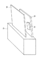
図3は、上記インクジェットプリンタの要部の構成を示す斜視図である。インクジェットプリンタ本体51の内部において、インクカートリッジ3はインクタンク2とともにインクキャリッジ1に搭載されている。インクキャリッジ1は、主走査方向に平行に配置された保持シャフト6a,6bにガイドされて主走査方向に往復移動する。インクキャリッジ1の背面側には、上側にスライドシャフト4が配置されており、このスライドシャフト4の下方にタイミングフェンス5が配置されている。タイミングフェンス5は、インクキャリッジ1の背面側に設けられている読取センサ8に対向する。
【0028】
図4は、上記インクジェットプリンタに設けられるインクキャリッジの構成を示す外観図である。インクキャリッジ1は、中空形状を呈し、内部にインクカートリッジ3及びインクタンク2が上面側からこの順に搭載される。インクキャリッジ1の背面側の下端部には、軸受1aが形成されている。この軸受1aには、背面側の保持シャフト6aが嵌入する。インクキャリッジ1の底面の前端部には、凹部1bが形成されている。この凹部1bには、前面側の保持シャフト6aが下方から当接する。また、インクキャリッジ1の一方の側面(図4では右側)の前面側の下端部には、突起1cが突出している。
【0029】
インクキャリッジ1は、インクジェットプリンタに対する電源投入時、及び、画像形成作業の開始時において主走査方向における移動範囲の右端側に移動して停止する。画像形成作業の開始が指示されると、インクキャリッジ1は移動範囲の左端側に移動した後、画像形成すべき用紙幅に応じた主走査方向における画像形成範囲内を往復移動する。
【0030】
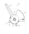
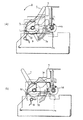
図5は、上記インクジェットプリンタに設けられる高さ変更部材としての操作レバーの構成を示す側面図である。インクジェットプリンタ本体51の一方の側面には、操作レバー7が配置されている。この操作レバー7は、基部としての円板状の基体7aの周面の一部から操作部7b、ストッパ7c(当接部)、係止片7d及びギア部7eを突出して形成されている。基体7aは、インクキャリッジ1の主走査方向に厚みを有している。また、操作レバー7は、インクジェットプリンタ本体51の内部において基体7aの中央の孔部7fを中心に図6の(A)に示す位置、及び、この位置から矢印A方向に所定角度だけ回転した図6の(B)に示す位置との間において回転自在に支持されている。
【0031】
操作部7bは、インクジェットプリンタ本体51の上面から外部に露出している。ギア部7eは、スライドシャフト4の回転軸の一端に固定されたアジャストギア4aに噛合している。
【0032】
ストッパ7cは、基体7aの半径方向周端に半径方向外方向きに突出して設けられ、操作レバー7の回転によってインクキャリッジ1の突起1cに当接する当接位置とインクキャリッジ1の突起1cに当接しない非当接位置とに選択的に変換される。このストッパ7cの突出量は、基体7aのインクキャリッジ主走査方向の厚みと一致している。係止片7dには、弾性部材9が係止されている。この弾性部材9は、操作レバー7を図6の(A)に示す位置、又は、図6の(B)に示す位置のいずれかに選択的に停止させるように付勢する。ストッパ7cは、操作レバー7が図6の(A)に示す位置に停止している状態ではインクキャリッジ1の突起1cとの当接位置に露出せずに非当接位置に変換され、操作レバー7が図6の(B)に示す位置に停止している状態ではインクキャリッジ1の突起1cに当接する位置に露出する。この場合、操作レバー7が図6の(A)に示す位置に停止している状態、つまりインクキャリッジ1の突起1cとの当接位置にストッパ7cが露出せずに非当接位置に変換されている状態では、インクキャリッジの主走査方向一側への走査時にインクキャリッジ1の突起1cがインクジェットプリンタ本体51の一方の側壁に当接するようになっている。また、インクキャリッジ1の突起1cの突出量は、ストッパ7cの突出量(基体7aの厚み)よりも大きく設定されている。
【0033】
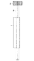
図7は、上記インクジェットプリンタに設けられるスライドシャフトの構成を示す正面図である。スライドシャフト4は、円柱形状を呈し、インクジェットプリンタ本体51の内部において、インクキャリッジ1の主走査方向の移動範囲の全域において、インクキャリッジ1の背面側の上部に当接する。スライドシャフト4は、一端にアジャストギア4aを固定した回転軸4bに対して中心軸を偏心して固定されている。前述のようにアジャストギア4aには、操作レバー7に形成されているギア部7fに噛合する。従って、スライドシャフト4は、操作レバー7の回転によって回転軸4bに対して偏心して回転し、スライドシャフト4の周面の前面側、即ち、インクキャリッジ1側への突出量が変化する。
【0034】
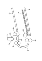
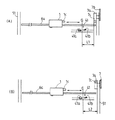
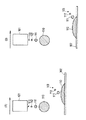
図8の(A)および(B)は、上記ストッパが操作レバーによって突起との当接位置および非当接位置に変換されている状態を模式的に示すインクジェットプリンタの正面図である。インクジェットプリンタ本体51の一方の側壁付近には、上記突起1cとストッパ7cとの当接または非当接に基づきインクキャリッジ1の主走査方向一側(図8では右側)での基準位置Gを検出する検出手段としてのインク残量センサ41が設けられている。このインク残量センサ41は、インクキャリッジ1に搭載されたインクタンク2内のインク残量を検出するものであって、インクタンク2に向けて光を発光する発光素子41aと、この発光素子41aから発光された光を受光する受光素子41bとを備えている。この場合、インクキャリッジ1の主走査方向一側での基準位置Gの検出は、インク残量センサ41によるインク残量検出位置と、突起1cとストッパ7cとの当接位置との間の距離L1に基づいて行われるようになっている。
【0035】
そして、上記インク残量センサ41により検出されたインクキャリッジ1の主走査方向一側での基準位置Gに基づいて上記操作レバー7による用紙Pの厚みに応じたインクキャリッジ1の用紙P表面からの高さつまりインクカートリッジ3のインクヘッドの高さ変更の正否が判定されるようになっている。つまり、インクキャリッジ1の画像形成に先立つ主走査方向一側への走査時に操作レバー7によるインクカートリッジ3のインクヘッドの高さ変更の正否が判定されるようになっていて、図8の(A)に示すように、操作レバー7が図6の(B)に示す位置に停止してストッパ7cを露呈させる当接位置に変換している状態でのインクキャリッジ1の主走査方向一側への走査時による基準位置Gからインクキャリッジ1の突起1cがストッパ7cに当接するまでの距離L1と、図6の(B)に示すように、操作レバー7が図6の(A)に示す位置に停止してストッパ7cを露呈させない非当接位置に変換している状態でのインクキャリッジ1の主走査方向一側への走査時による基準位置Gからインクキャリッジ1の突起1cがストッパ7cに非当接となってインクジェットプリンタ本体51の一方の壁面に当接するまでの距離L2との相違をインクキャリッジ1を駆動する駆動モータとしてのモータ30(図9に表れる)の駆動時間によって検出することで、操作レバー7による用紙Pの厚みに応じたインクカートリッジ3のインクヘッドの用紙P表面からの高さ変更の正否が判定されるようにしている。なお、インクキャリッジ1の画像形成に先立つ主走査方向一側への走査時のインク残量センサ41から突起1cがストッパ7cに当接するまでの距離L1と突起1cがインクジェットプリンタ本体51の一方の側壁に当接するまでの距離L2との相違は、インクキャリッジ1を走査するモータ30のパルス数の差、または負荷抵抗の変化に基づいて検出されるようにしてもよい。
【0036】
操作レバー7が図6の(A)に示す位置に停止している状態では、スライドシャフト4の前面側への突出量は小さく、インクキャリッジ1の背面はスライドシャフト4の周面によって押圧されず、インクキャリッジ1の前面側は下側の位置に停止している。これに対して、操作レバー7が図6の(B)に示す位置に停止している状態では、スライドシャフト4の前面側への突出量が大きくなり、インクキャリッジ1の背面はスライドシャフト5の周面によって押圧され、インクキャリッジ1は保持シャフト6aを中心として回転し、インクキャリッジ1の前面側は上側の位置に停止する。このとき、インクキャリッジ1に搭載されたインクカートリッジ3の下端のインクヘッドは、図6の(A)に示す状態に比較して0.2〜0.7mm程度上方に位置する。従って、操作レバー7を図6の(A)に示す位置、又は、図6の(B)に示す位置に選択的に回転させることにより、インクキャリッジ1に搭載したインクカートリッジ3のインクヘッドを普通紙に対応した下側位置、又は、厚紙に対応した上側位置のいずれかに位置する状態で、主走査方向に往復移動させることができる。また、インクキャリッジ1に搭載したインクカートリッジ3のインクヘッドが普通紙に対応した下側位置に位置している状態では操作レバー7のストッパ7cはインクキャリッジ1の突起1cに当接する位置に露出せず、インクキャリッジ1に搭載したインクカートリッジ3のインクヘッドが厚紙に対応した上側位置に位置している状態で操作レバー7のストッパ7cがインクキャリッジ1の突起1cに当接する位置に露出する。
【0037】
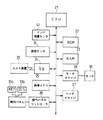
図9は、上記インクジェットプリンタの制御部の構成を示すブロック図である。インクジェットプリンタの制御部は、ROM22及びRAM23を備えたCPU21に、インク残量センサ41、読取センサ8、インタフェース24、画像メモリ25、モータドライバ26、ヘッドドライバ27及び操作パネルコントローラ28等の入出力機器を接続して構成されている。CPU21は、ROM22に予め書き込まれたプログラムにしたがって入出力機器を統括して制御する。この時、CPU21に入出力されるデータがRAM23の所定のメモリエリアに格納される。
【0038】
読取センサ8は、タイミングフェンス5の読取データをCPU21に入力する。インタフェース24は、パーソナルコンピュータ等のホスト装置29からのデータの入力を受け付ける。画像メモリ25は、インタフェース24を介して入力された画像データを記憶する。モータドライバ26はCPU21から出力される駆動データに基づいてモータ30を駆動する。このモータ30の回転が、図外の伝達機構を介してインクキャリッジ1に主走査方向の移動力として伝達される。ヘッドドライバ27は、CPU21から出力される駆動データに基づいてインクカートリッジ3のインクヘッドを駆動する。操作パネルコントローラ28は、操作パネル31に設けられたキースイッチ31aの操作データをCPU21に入力するとともに、CPU21から出力される表示データを表示部としてのディスプレイ31bに表示する。また、ディスプレイ31bには、パーソナルコンピュータ等のホスト装置29からの画像形成要求時に条件設定される用紙Pの厚みと、用紙Pの厚みに応じて変更された操作レバー7によるインクカートリッジ3のインクヘッドの用紙P表面からの高さとが不適切であるときに、操作レバー7による位置変更を促す旨のメッセージが表示されるようになっている。そして、インクカートリッジ3のインクヘッドの用紙P表面からの高さは、突起1cとストッパ7cとの当接または非当接に基づいて検出されたインクキャリッジ1の主走査方向一側での基準位置Gと、パーソナルコンピュータ等のホスト装置29からの画像形成要求時に条件設定される用紙Pの厚みとに基づいて決定されるようになっている。
【0039】
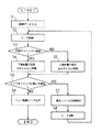
図10は、上記インクジェットプリンタの制御部におけるインクカートリッジの高さ検出処理時の処理手順を示すフローチャートである。この発明に係るインクジェットプリンタの制御部を構成するCPU21は、突起1cとストッパ7cとの当接または非当接に基づきインクキャリッジ1の主走査方向一側(図8では右側)での基準位置Gをインク残量センサ41により検出し、このインク残量センサ41により検出されたインクキャリッジ1の主走査方向一側での基準位置Gからインクキャリッジ1の突起1cがストッパ7cに当接するまでの距離L1と、基準位置Gからインクキャリッジ1の突起1cがインクジェットプリンタ本体51の一方の壁面に当接するまでの距離L2との相違をインクキャリッジ1を駆動するモータ30の駆動時間によって検出し、さらに、この検出結果に基づいて操作レバー7の操作によってインクキャリッジ1に搭載したインクカートリッジ3のインクヘッドが普通紙に対応した下側位置、又は、厚紙に対応した上側位置のいずれに設定されているかを判定する。
【0040】
即ち、CPU21は、ホスト装置29から画像形成要求時に条件設定される用紙Pの厚みのでーたを含む画像データが入力されると(s1)、インクキャリッジ1を右端方向に所定位置まで移動させるべくモータ30を駆動する(s2)。このとき、CPU21は、モータ30の駆動中に突起1cとストッパ7cとの当接または非当接に基づいてインクキャリッジ1の主走査方向一側での基準位置Gをインク残量センサ41により検出し、基準位置Gからインクキャリッジ1の突起1cがストッパ7cに当接するまでの距離L1と、基準位置Gからインクキャリッジ1の突起1cがインクジェットプリンタ本体51の一方の壁面に当接するまでの距離L2との相違をインクキャリッジ1を駆動するモータ30の駆動時間によって検出する。そして、この検出結果から、インクキャリッジ1の突起1cがストッパ7cに当接しているか否かを判定し、その判定結果に基づいて操作レバー7の操作によってインクキャリッジ1に搭載したインクカートリッジ3のインクヘッドが普通紙に対応した下側位置、又は、厚紙に対応した上側位置のいずれに設定されているかを判断する(s3〜s5)。そして、パーソナルコンピュータ等のホスト装置29からの画像形成要求時に条件設定された用紙Pの厚みと、用紙Pの厚みに応じて変更された操作レバー7によるインクカートリッジ3のインクヘッドの用紙P表面からの高さとが不適切であるか否かを判定し(s6)、パーソナルコンピュータ等のホスト装置29からの画像形成要求時に条件設定された用紙Pの厚みと、用紙Pの厚みに応じて変更された操作レバー7によるインクカートリッジ3のインクヘッドの用紙P表面からの高さとが不適切である場合には、操作パネル31のディスプレイ31bに操作レバーによる位置変更を促すメッセージを表示し(s7)、モータ30を所定量だけ逆転してs2に戻る(s8→s2)。s6において、パーソナルコンピュータ等のホスト装置29からの画像形成要求時に条件設定された用紙Pの厚みと、用紙Pの厚みに応じて変更された操作レバー7によるインクカートリッジ3のインクヘッドの用紙P表面からの高さとが適切である場合には、CPU21はヘッドドライバ27に対してホスト装置29から入力された画像データに応じたヘッドの駆動データを出力して画像形成処理を実行する(s9)。
【0041】
以上の処理により、突起1cとストッパ7cとの当接または非当接に基づいてインクキャリッジ1の主走査方向一側での基準位置Gを検出する既存のインク残量センサ41を用いて、基準位置Gからインクキャリッジ1の突起1cがストッパ7cに当接するまでの距離L1と、基準位置Gからインクキャリッジ1の突起1cがインクジェットプリンタ本体51の一方の壁面に当接するまでの距離L2との相違をモータ30の駆動時間によって検出してから、この検出結果に基づいて操作レバー7の操作によってインクキャリッジ1に搭載したインクカートリッジ3のインクヘッドが普通紙に対応した下側位置、又は、厚紙に対応した上側位置のいずれに設定されているかを判定し、パーソナルコンピュータ等のホスト装置29からの画像形成要求時に条件設定された用紙Pの厚みと、用紙Pの厚みに応じて変更された操作レバー7によるインクカートリッジ3のインクヘッドの用紙P表面からの高さとが適切である場合にのみ画像形成処理を実行する。したがって、上記の処理により、画像形成処理の対象として給紙トレイ52から給紙される用紙Pの厚さに応じた位置にインクカートリッジ3のインクヘッドを確実に位置させることができ、画像形成時のインクヘッドと用紙P表面との間隔が狭い際の用紙P表面へのインクヘッドの接触によるインクヘッドの磨耗や破損を確実に防止することができる上、インクヘッドと用紙P表面との間隔が広い際の所謂サテライト現象による画像形成状態の劣化を確実の防止することができる。
【0042】
また、通常、インクジェットプリンタでは、電源オン時や画像形成処理の開始前において、インクキャリッジ1を一方の側壁側に移動させる。これとともに、操作性を考慮して操作レバー7はインクジェットプリンタ本体の一方の側壁に設けられている。このため、上記の実施形態では、インクジェットプリンタ本体51の一方の側壁付近にインク残量センサ41を配置し、電源オン時や画像形成処理の開始前にインクキャリッジ1が位置している装置の一方の側壁側でインクカートリッジ3のインクヘッドの用紙P表面からの高さを検出するようにし、検出部材の大型化やインクキャリッジ1の無駄な移動を省くようにしている。即ち、電源オン時や画像形成処理の開始前において、インクキャリッジ1を一方の側壁側に移動させる動作によって、同時にインクカートリッジ3のインクヘッドの用紙P表面からの高さを検出することができる。
【0043】
しかも、突起1cの突出量がストッパ7の厚みよりも大きく設定されているので、ストッパ7cを突起1cに対し非当接にする位置に操作レバー7の基体7aを変換した状態であっても、突起1cがインクジェットプリンタ本体51の一側壁面に確実に当接することになり、操作レバー7による用紙Pの厚みに応じたインクカートリッジ3のインクヘッドの用紙P表面からの高さ変更の正否を精度よく判定することができる。
【0044】
また、突起1cとストッパ7cとの当接または非当接に基づいてインクキャリッジ1の主走査方向一側での基準位置Gを検出する検出手段として、インクキャリッジ1に搭載されたインクタンク2内のインク残量を検出するインク残量センサ41を適用しているので、新たに検出手段を付設する必要がなく、既存のインク残量センサ41を利用してインクキャリッジ1の主走査方向一側での基準位置Gが検出されることになり、インク残量センサ41の共用化によるコストの低廉化を図ることができる。
【0045】
また、インクキャリッジ1の主走査方向一側での基準位置Gの検出が、インク残量センサ41によるインク残量検出位置と、突起1cとストッパ7cとの当接位置との間の距離L1に基づいて行われるようになっているので、インクキャリッジ1の主走査方向一側での基準位置Gを簡単に検出することができる。
【0046】
しかも、インクキャリッジ1の画像形成に先立つ主走査方向一側への走査時のインク残量検出位置から突起1cがストッパ7cに当接するまでの距離L1と突起1cがインクジェットプリンタ本体51の一方の側壁に当接するまでの距離L2との相違が、インクキャリッジ1を走査するモータ30の駆動時間の差に基づいて検出され、この検出結果に基づいて操作レバー7による用紙Pの厚みに応じたインクカートリッジ3のインクヘッドの用紙P表面からの高さ変更の正否が判定されることにより、インクキャリッジ1の主走査方向一側への走査時のインク残量検出位置から突起1cがストッパ7cに当接するまでの距離L1と突起1cがインクジェットプリンタ本体51の一方の側壁に当接するまでの距離L2との相違が新たな手段を付設することなく容易に検出され、操作レバー7による用紙Pの厚みに応じたインクカートリッジ3のインクヘッドの用紙P表面からの高さ変更の正否を容易に判定することができることになる。
【0047】
また、インクカートリッジ3のインクヘッドの用紙P表面からの高さが、突起1cとストッパ7cとの当接または非当接に基づいて検出されたインクキャリッジ1の主走査方向一側での基準位置Gと、パーソナルコンピュータ等のホスト装置29からの画像形成要求時に条件設定される用紙Pの厚みとに基づいて決定されるようにしているので、インクキャリッジ1の主走査方向一側での基準位置Gに基づいた操作レバー7による用紙Pの厚みに応じたインクカートリッジ3のインクヘッドの用紙P表面からの高さ変更の正否判定の結果と、ホスト装置29からの画像形成要求時に条件設定された用紙Pの厚みとによって、インクカートリッジ3のインクヘッドの用紙P表面からの高さを正確に決定することができる。
【0048】
更に、パーソナルコンピュータ等のホスト装置29からの画像形成要求時に条件設定された用紙Pの厚みと、用紙Pの厚みに応じて変更された操作レバー7によるインクカートリッジ3のインクヘッドの用紙P表面からの高さとが不適切である場合に、操作パネル31のディスプレイ31bに操作レバーによる位置変更を促すメッセージが表示されるので、ユーザがディスプレイ31bを一目見て、操作レバー7による用紙Pの厚みに応じたインクカートリッジ3のインクヘッドの用紙P表面からの高さ変更が不適切であることを認識することができる。
【0049】
なお、本発明は、上記実施形態に限定されるものではなく、その他種々の変形例を包含している。例えば、上記実施形態では、ストッパ7cを、基体7aの半径方向周端に半径方向外方向きに突出して設け、基体7aの厚みと同一の厚さとしたが、基体の中央の孔部を偏心させて設けるとともに、この基体よりインクキャリッジの一側壁に向かって突出する当接部(ストッパ)を設け、この当接部が操作レバーの回転によってインクキャリッジの突起に当接する当接位置とインクキャリッジの突起に当接しない非当接位置とに選択的に変換されるようにしてもよい。
【0050】
また、これとは逆に、インクキャリッジの主走査方向一側の壁面と対応するインクジェットプリンタ本体の一側壁に、インクカートリッジのインクヘッドの用紙表面からの高さを用紙の厚みに応じて変更する操作レバーの基体を設け、この操作レバーの基体に、インクキャリッジに向かって突出する突起を設ける。そして、インクキャリッジの主走査方向一側の壁に、そのインクキャリッジの主走査方向一側への走査によって突起と当接する当接部を設けるとともに、突起と当接しない孔部を設け、用紙の厚みに応じた操作レバーの基体の変更動作に応じて突起を当接部に当接させる位置と突起を孔部に挿通させる位置とに当接部と孔部とを変換させるようにしてもよい。
【0051】
更に、インクキャリッジ1の主走査方向に厚みを有する操作レバーの基体自身によって当接部(ストッパ)が構成されていてもよく、この場合においても、基体の中央の孔部を偏心させて設ける必要があり、操作レバーの基体が当接部を非当接にする位置に変換されたときには、インクキャリッジの主走査方向一側への走査時に突起をインクジェットプリンタ本体の一側壁面に当接させるようにする。この場合には、互いに当接または非当接する突起と当接部との構成を非常に簡単なものにすることができる。
【0052】
【発明の効果】
以上、要するに、突起と当接部との当接または非当接に基づくインクキャリッジの主走査方向一側での基準位置を既存の簡単な構成の検出手段により検出し、そのインクキャリッジの基準位置に基づいて高さ変更部材による用紙の厚みに応じたインクキャリッジの用紙表面からの高さ変更の正否を判定することで、用紙表面へのインクヘッドの接触によるインクヘッドの磨耗や破損を確実に防止することができる上、所謂サテライト現象による画像形成状態の劣化を確実の防止することができる。
【0053】
特に、高さ変更部材の基部自身によって当接部を構成し、この当接部を突起に対し非当接にする位置に高さ変更部材の基部を変換した状態で突起をインクジェットプリンタ本体の一側壁面に当接させるようにすることで、互いに当接または非当接する突起と当接部との構成を非常に簡単なものにすることができる。
【0054】
そして、突起の突出量を当接部の厚みよりも大きく設定することで、インクジェットプリンタ本体の一側壁面に突起を確実に当接させて、高さ変更部材による用紙の厚みに応じたインクキャリッジの用紙表面からの高さ変更の正否を精度よく判定することができる。
【0055】
また、インクキャリッジに搭載されたインクタンク内のインク残量を検出するインク残量検出手段を検出手段として適用することで、新たに検出手段を付設せずに既存のインク残量検出手段を利用してインクキャリッジの主走査方向一側での基準位置を検出し、インク残量検出手段の共用化によるコストの低廉化を図ることができる。
【0056】
そして、インク残量検出手段によるインク残量検出位置と、突起と当接部との当接位置との間の距離に基づいてインクキャリッジの主走査方向一側での基準位置の検出を行うことで、インクキャリッジの主走査方向一側での基準位置を簡単に検出することができる。
【0057】
また、インクキャリッジの画像形成に先立つ主走査方向一側への走査時のインク残量検出位置から突起が当接部に当接するまでの距離と突起が非当接となるまでの距離との相違を、インクキャリッジを走査する駆動モータの駆動時間、パルス数、または負荷抵抗の変化に基づいて検出し、この検出結果に基づいて高さ変更部材による用紙の厚みに応じたインクキャリッジの用紙表面からの高さ変更の正否を判定することで、インクキャリッジの主走査方向一側への走査時のインク残量検出位置から突起が当接部に当接するまでの距離と突起が非当接となるまでの距離との相違を新たな手段を付設することなく容易に検出でき、高さ変更部材による用紙の厚みに応じたインクキャリッジの用紙表面からの高さ変更の正否を容易に判定することができる。
【0058】
加えて、突起と当接部との当接または非当接に基づいて検出されたインクキャリッジの主走査方向一側での基準位置と、画像形成要求時に条件設定される用紙の厚みとに基づいてインクキャリッジの用紙表面からの高さを決定することで、インクキャリッジの用紙表面からの高さを正確に決定することができる。
【0059】
更に、画像形成要求時に条件設定される用紙の厚みと、用紙の厚みに応じて変更した高さ変更部材によるインクキャリッジの用紙表面からの高さとが不適切であるときに、その旨をインクジェットプリンタ本体の表示部に表示することで、高さ変更部材による用紙の厚みに応じたインクキャリッジの用紙表面からの高さ変更が不適切であることを表示部を一目見て認識することができる。
【図面の簡単な説明】
【図1】本発明の実施形態に係るインクジェットプリンタの外観図である。
【図2】インクジェットプリンタの概略の構成を示す側面図である。
【図3】インクジェットプリンタの要部の構成を示す斜視図である。
【図4】インクジェットプリンタに設けられるキャリッジの構成を示す外観図である。
【図5】インクジェットプリンタに設けられる操作レバーの構成を示す側面図である。
【図6】(A)は操作レバーの非当接位置への操作によるキャリッジに搭載されたインクカートリッジの移動状態を説明する図である。
(B)は操作レバーの当接位置への操作によるキャリッジに搭載されたインクカートリッジの移動状態を説明する図である。
【図7】インクジェットプリンタに設けられるスライドシャフトの構成を示す正面図である。
【図8】(A)はストッパが操作レバーによって突起との当接位置に変換されている状態を模式的に示すインクジェットプリンタの正面図である。
(B)はストッパが操作レバーによって突起との非当接位置に変換されている状態を模式的に示すインクジェットプリンタの正面図である。
【図9】インクジェットプリンタの制御部の構成を示すブロック図である。
【図10】インクジェットプリンタの制御部におけるインクカートリッジの高さ検出処理時の処理手順を示すフローチャートである。
【図11】(A)は一般的なインクジェットプリンタにおけるインクカートリッジのインクヘッドと用紙表面との間隔適正状態でのサテライト現象の非発生状況を説明する図である。
(B)は一般的なインクジェットプリンタにおけるインクカートリッジのインクヘッドと用紙表面との間隔不適正状態でのサテライト現象の発生状況を説明する図である。
【符号の説明】
1 インクキャリッジ
1c 突起
51 インクジェットプリンタ本体
7 操作レバー(高さ変更部材)
7a 基体(基部)
7c ストッパ(当接部)
30 モータ(駆動モータ)
31b ディスプレイ(表示部)
41 インク残量センサ(インク残量検出手段)
(検出手段)
G インクキャリッジの基準位置
L1 インク残量検出位置から突起が当接部に当接するまでの距離
L2 インク残量検出位置から突起が非当接となるまでの距離
P 用紙[0001]
TECHNICAL FIELD OF THE INVENTION
The present invention relates to an ink jet printer that forms an image on a surface of a sheet conveyed in a sub-scanning direction by reciprocating a head in a main scanning direction.
[0002]
[Prior art]
Generally, in an ink jet printer, an ink head is mounted on an ink carriage that reciprocates in a main scanning direction with respect to a sheet conveyed in a sub-scanning direction, and the ink is ejected from the ink head based on image information. An image is formed on the image. For example, in an ink jet printer, ink is ejected from a plurality of nozzles arranged in an ink head onto the surface of a sheet, and nozzles for forming an image on the surface of the sheet with the ink ejected from the nozzles normally. The appropriate distance between the leading edge of the sheet and the surface of the sheet is predetermined (for example, see Patent Document 1).
[0003]
In this case, if the distance between the ink head and the surface of the paper is too small, the surface of the paper comes into contact with the ink head, causing wear and breakage of the ink head. Conversely, if the distance between the ink head and the surface of the paper is too wide, a so-called satellite phenomenon occurs, and the image forming state deteriorates. The satellite phenomenon is a phenomenon in which fine ink particles ejected from the nozzles of the ink head following the main particles of the ejected ink adhere to landing points on the surface of the paper that are far from the landing points of the main particles. That is, as shown in FIG. 11A, when the distance between the
[0004]
Therefore, a conventional ink-jet printer is configured so that the position of the ink head can be moved together with the ink carriage in a direction (height direction) orthogonal to the surface of the paper, and the ink in the height direction according to the thickness of the paper on which an image is formed. By changing the position of the head, the separation distance (height) between the paper surface and the ink head is kept constant regardless of the thickness of the paper. Normally, such a height change of the ink head is performed for each ink carriage by a user operating a lever-type height changing member disposed on a side surface of the apparatus.
[0005]
[Patent Document 1]
JP-A-60-178063
[0006]
[Problems to be solved by the invention]
However, in the above-described conventional ink jet printer, there is no device for detecting the height change position of the ink carriage from the paper surface changed by the height changing member with a simple configuration, and the thickness of the paper by the height changing member is not detected. It is not possible to determine whether or not the height change of the ink carriage from the surface of the paper according to the above is correct. Therefore, even when the height of the ink carriage changed by the user with the height changing member does not match the thickness of the sheet on which the image is formed, the image forming process is executed, and a so-called satellite phenomenon occurs to cause an image forming state. Is deteriorated, or the ink head is worn or damaged.
[0007]
The present invention has been made in view of such a point, and an object of the present invention is to use a simple configuration to determine whether or not a height change from a paper surface of an ink carriage according to a thickness of a paper by a height changing member is correct. An object of the present invention is to provide an ink jet printer that enables determination.
[0008]
[Means for Solving the Problems]
In order to achieve the above object, a solution taken by the present invention is to form an image on a sheet by discharging ink from an ink head mounted on an ink carriage scanned in a main scanning direction based on image information. Assume an inkjet printer. Then, a projection is provided on a wall surface on one side in the main scanning direction of the ink carriage, and the height of the ink carriage from the surface of the paper is changed according to the thickness of the paper on one side wall of the ink jet printer body corresponding to the projection. A base portion of the height changing member is provided, and a contact portion that comes into contact with the projection by scanning the ink carriage in one side in the main scanning direction is provided at a base portion of the height changing member. According to the operation of changing the base of the height changing member according to the thickness of the sheet, the position is changed between a position where the contact portion is brought into contact with the projection and a position where the contact portion is brought into non-contact. . Further, near one side wall of the ink jet printer main body, a detecting means for detecting a reference position on one side in the main scanning direction of the ink carriage based on contact or non-contact between the protrusion and the contact portion is provided. Based on a reference position on one side of the main scanning direction of the ink carriage detected by the detection means, it is determined whether or not the height change from the paper surface of the ink carriage according to the thickness of the paper by the height changing member is correct. ing.
[0009]
According to this specific matter, whether the height of the ink carriage is changed from the paper surface in accordance with the thickness of the paper by the height changing member is determined based on the contact or non-contact between the protrusion and the contact portion. Since the detection is performed based on the reference position of the ink carriage by the existing simple detection means for detecting the reference position on one side in the main scanning direction, the paper surface of the ink carriage changed by the height changing member by the user. It is accurately determined whether or not the height of the ink head conforms to the thickness of the paper on which an image is formed. While it is possible to reliably prevent the abrasion and breakage of the ink head due to contact, the deterioration of the image forming state due to the so-called satellite phenomenon when the distance between the ink head and the paper surface is wide. It becomes possible to prevent reliably.
[0010]
In particular, the following configuration is given as a specific example of the relationship between the protrusion and the contact portion.
[0011]
In other words, in the state where the base portion of the height changing member having a thickness in the main scanning direction of the ink carriage itself constitutes the contact portion, and the base portion of the height changing member is converted to a position where the contact portion does not contact. When the ink carriage is scanned in one side in the main scanning direction, the protrusion is brought into contact with one side wall surface of the ink jet printer main body.
[0012]
According to this specific matter, the contact portion is constituted by the base of the height changing member itself, and the protrusion is formed in a state where the base of the height changing member is converted to a position where the contact portion does not contact the projection. Are configured to abut on one side wall surface of the ink jet printer main body, so that the configuration of the projection and the abutting portion abutting or non-abutting with each other can be made very simple.
[0013]
Here, when the protrusion amount of the protrusion is set to be larger than the thickness of the contact portion, the base of the height changing member is changed to a position where the contact portion is not in contact with the protrusion. Even so, the protrusions will surely abut the one side wall surface of the ink jet printer main body, and it is possible to accurately determine whether the height change member has changed the height of the ink carriage from the paper surface according to the thickness of the paper. Becomes possible.
[0014]
In particular, the following configuration is provided to specifically specify the detection means.
[0015]
That is, an ink remaining amount detecting unit that detects the remaining amount of ink in the ink tank mounted on the ink carriage is applied as the detecting unit.
[0016]
According to this specific matter, it is not necessary to newly add a detecting means, and the reference position on one side in the main scanning direction of the ink carriage is detected by using the existing ink remaining amount detecting means. It is possible to reduce the cost due to the construction.
[0017]
Further, the detection of the reference position on one side of the ink carriage in the main scanning direction is performed based on the distance between the remaining ink amount detection position by the remaining ink amount detection means and the contact position between the protrusion and the contact portion. In this case, it is possible to easily detect the reference position on one side of the ink carriage in the main scanning direction.
[0018]
Then, the difference between the distance from the ink remaining amount detection position at the time of scanning to one side in the main scanning direction prior to the image formation of the ink carriage until the protrusion comes into contact with the contact portion and the distance until the protrusion becomes non-contact. Is detected based on the drive time of the drive motor that scans the ink carriage, the number of pulses, or a change in load resistance. If the height change of the ink carriage is determined, the distance from the ink remaining amount detection position when scanning the ink carriage to one side in the main scanning direction until the protrusion contacts the contact portion and the protrusion are determined. The difference from the distance until non-contact is easily detected without adding new means, and whether the height change member has changed the height of the ink carriage from the paper surface in accordance with the thickness of the paper can be determined. It is possible to determine the.
[0019]
Further, the height of the ink carriage from the paper surface is determined based on the reference position on one side in the main scanning direction of the ink carriage, which is detected based on the contact or non-contact between the protrusion and the contact portion. When the condition is set based on the thickness of the sheet, the ink carriage according to the thickness of the sheet by the height changing member based on the reference position on one side of the main scanning direction of the ink carriage. The height of the ink carriage from the surface of the paper can be accurately determined based on the result of the determination as to whether the height has been changed from the surface of the paper and the thickness of the paper that has been set when the image formation is requested.
[0020]
Further, the display section provided in the ink jet printer main body shows that the thickness of the paper set as a condition at the time of an image forming request and the height of the ink carriage from the paper surface by the height changing member changed according to the thickness of the paper are not correct. If it is appropriate to indicate this, the user looks at the display unit at a glance and changes the height of the ink carriage from the paper surface according to the thickness of the paper using the height changing member. It becomes possible to recognize that it is inappropriate.
[0021]
On the other hand, the following configuration is provided assuming that a protrusion is provided on the base of the height changing member, contrary to one side wall of the ink jet printer main body.
[0022]
That is, a base of a height changing member that changes the height of the ink carriage from the paper surface in accordance with the thickness of the paper is provided on one side wall of the ink jet printer main body corresponding to the wall surface on one side of the main scanning direction of the ink carriage, At the base of the height changing member, a projection protruding toward the ink carriage is provided. A contact portion is provided on a wall of the ink carriage on one side in the main scanning direction, the contact portion being in contact with the projection by scanning the ink carriage in one side in the main scanning direction, and the contact portion is determined according to the thickness of the sheet. According to the changing operation of the base of the height changing member, the position is changed between a position where the protrusion is brought into contact with the protrusion and a position where the protrusion is brought into non-contact. Further, near one side wall of the ink jet printer main body, there is provided detecting means for detecting a reference position on one side in the main scanning direction of the ink carriage based on contact or non-contact between the protrusion and the contact portion, Based on a reference position on one side of the main scanning direction of the ink carriage detected by the detection means, it is determined whether or not the height change from the paper surface of the ink carriage according to the thickness of the paper by the height changing member is correct. ing.
[0023]
According to this specific matter, whether the height of the ink carriage is changed from the paper surface in accordance with the thickness of the paper by the height changing member is determined based on the contact or non-contact between the protrusion and the contact portion. Since the detection is performed based on the reference position of the ink carriage by the existing simple detection means for detecting the reference position on one side in the main scanning direction, the paper surface of the ink carriage changed by the height changing member by the user. The determination as to whether or not the height from the height conforms to the thickness of the sheet on which the image is formed is similarly accurately performed.
[0024]
BEST MODE FOR CARRYING OUT THE INVENTION
FIG. 1 is an external view of a serial type inkjet printer according to an embodiment of the present invention, and FIG. 2 is a side view showing a schematic configuration of the inkjet printer. On the front side of the
[0025]
Inside the ink jet printer
[0026]
The holding
[0027]
FIG. 3 is a perspective view illustrating a configuration of a main part of the inkjet printer. Inside the ink jet printer
[0028]
FIG. 4 is an external view illustrating a configuration of an ink carriage provided in the inkjet printer. The
[0029]
The
[0030]
FIG. 5 is a side view showing a configuration of an operation lever as a height changing member provided in the inkjet printer. The operation lever 7 is arranged on one side surface of the ink jet printer
[0031]
The
[0032]
The
[0033]
FIG. 7 is a front view showing a configuration of a slide shaft provided in the inkjet printer. The
[0034]
FIGS. 8A and 8B are front views of the ink jet printer schematically showing a state in which the stopper is changed to a contact position and a non-contact position with the protrusion by the operation lever. In the vicinity of one side wall of the ink jet printer
[0035]
Then, based on the reference position G on one side in the main scanning direction of the
[0036]
When the operation lever 7 is stopped at the position shown in FIG. 6A, the amount of protrusion of the
[0037]
FIG. 9 is a block diagram illustrating a configuration of a control unit of the inkjet printer. The control unit of the inkjet printer includes input / output devices such as an ink remaining
[0038]
The reading
[0039]
FIG. 10 is a flowchart showing a processing procedure at the time of detecting the height of the ink cartridge in the control unit of the inkjet printer. The
[0040]
That is, when image data including the thickness of the sheet P set as a condition at the time of an image forming request is input from the host device 29 (s1), the
[0041]
With the above-described processing, the existing ink remaining
[0042]
Usually, in an ink jet printer, the
[0043]
Moreover, since the protrusion amount of the
[0044]
As a detecting means for detecting the reference position G on one side in the main scanning direction of the
[0045]
The detection of the reference position G on one side of the
[0046]
In addition, the distance L1 from the detection position of the remaining amount of ink when scanning to one side in the main scanning direction prior to image formation of the
[0047]
The reference position on one side in the main scanning direction of the
[0048]
Further, the thickness of the paper P set as a condition at the time of an image formation request from a
[0049]
Note that the present invention is not limited to the above-described embodiment, but includes various other modifications. For example, in the above-described embodiment, the
[0050]
Conversely, the height of the ink head of the ink cartridge from the surface of the paper is changed according to the thickness of the paper on one side wall of the ink jet printer body corresponding to the wall of the ink carriage on one side in the main scanning direction. A base of the operation lever is provided, and a protrusion protruding toward the ink carriage is provided on the base of the operation lever. Then, on the wall on one side of the ink carriage in the main scanning direction, a contact portion that comes into contact with the projection by scanning the ink carriage in one side in the main scanning direction is provided, and a hole that does not come into contact with the projection is provided. The contact portion and the hole may be changed between a position where the protrusion contacts the contact portion and a position where the protrusion is inserted into the hole according to the operation of changing the base of the operation lever according to the thickness. .
[0051]
Further, the contact portion (stopper) may be formed by the base itself of the operation lever having a thickness in the main scanning direction of the
[0052]
【The invention's effect】
In short, the reference position on one side in the main scanning direction of the ink carriage based on the contact or non-contact between the protrusion and the contact portion is detected by the existing simple detection means, and the reference position of the ink carriage is detected. By determining whether the height of the ink carriage has changed from the paper surface according to the thickness of the paper by the height change member based on the height of the paper, wear and breakage of the ink head due to the contact of the ink head with the paper surface can be ensured. In addition, the deterioration of the image forming state due to the so-called satellite phenomenon can be reliably prevented.
[0053]
In particular, the contact portion is constituted by the base of the height changing member itself, and the projection is moved to a position where the contact portion is not brought into contact with the projection, and the projection is moved to the position of the inkjet printer main body in a state where the base of the height changing member is changed. By making contact with the side wall surface, it is possible to make the configuration of the protrusion and the contact portion that contact or non-contact with each other very simple.
[0054]
By setting the amount of protrusion of the protrusion to be greater than the thickness of the contact portion, the protrusion is reliably brought into contact with one side wall surface of the ink jet printer main body, and the ink carriage according to the thickness of the paper by the height changing member. Can be accurately determined whether or not the height change from the sheet surface.
[0055]
In addition, by applying the remaining ink amount detecting means for detecting the remaining amount of ink in the ink tank mounted on the ink carriage as the detecting means, the existing ink remaining amount detecting means can be used without adding a new detecting means. Thus, the reference position on one side of the ink carriage in the main scanning direction is detected, and the cost can be reduced by sharing the ink remaining amount detecting means.
[0056]
And detecting a reference position on one side of the ink carriage in the main scanning direction based on a distance between a remaining ink detection position detected by the remaining ink detection unit and a contact position between the protrusion and the contact portion. Thus, the reference position on one side of the ink carriage in the main scanning direction can be easily detected.
[0057]
Also, the difference between the distance from the ink remaining amount detection position when scanning to one side in the main scanning direction prior to image formation of the ink carriage until the protrusion comes into contact with the contact portion and the distance until the protrusion comes into non-contact. Is detected based on the drive time of the drive motor that scans the ink carriage, the number of pulses, or a change in load resistance. By judging whether the height change is correct or not, the distance from the ink remaining amount detection position when scanning the ink carriage to one side in the main scanning direction until the protrusion comes into contact with the contact portion and the protrusion become non-contact. And the height change member can easily determine whether or not the height change from the paper surface of the ink carriage according to the thickness of the paper by the height changing member. Kill.
[0058]
In addition, based on a reference position on one side in the main scanning direction of the ink carriage detected based on the contact or non-contact between the protrusion and the contact portion, and the thickness of the sheet set as a condition when an image forming request is made. By determining the height of the ink carriage from the surface of the paper, the height of the ink carriage from the surface of the paper can be accurately determined.
[0059]
Further, when the thickness of the paper set as a condition at the time of an image formation request and the height of the ink carriage from the paper surface by the height changing member changed according to the thickness of the paper are inappropriate, the fact is described. By displaying on the display unit of the main body, it is possible to recognize at a glance the display unit that the height change from the sheet surface of the ink carriage according to the sheet thickness by the height changing member is inappropriate.
[Brief description of the drawings]
FIG. 1 is an external view of an inkjet printer according to an embodiment of the present invention.
FIG. 2 is a side view illustrating a schematic configuration of the ink jet printer.
FIG. 3 is a perspective view illustrating a configuration of a main part of the inkjet printer.
FIG. 4 is an external view illustrating a configuration of a carriage provided in the inkjet printer.
FIG. 5 is a side view illustrating a configuration of an operation lever provided in the inkjet printer.
FIG. 6A is a diagram illustrating a state of movement of an ink cartridge mounted on a carriage due to operation of an operation lever to a non-contact position.
FIG. 4B is a diagram illustrating a state of movement of the ink cartridge mounted on the carriage due to operation of the operation lever to the contact position.
FIG. 7 is a front view illustrating a configuration of a slide shaft provided in the inkjet printer.
FIG. 8A is a front view of the ink jet printer schematically showing a state in which the stopper is changed to a contact position with a protrusion by an operation lever.
FIG. 4B is a front view of the ink jet printer schematically showing a state in which the stopper has been changed to a non-contact position with the protrusion by the operation lever.
FIG. 9 is a block diagram illustrating a configuration of a control unit of the inkjet printer.
FIG. 10 is a flowchart illustrating a procedure of a process of detecting a height of an ink cartridge in a control unit of the inkjet printer.
FIG. 11A is a diagram illustrating a non-occurrence state of a satellite phenomenon in a state where a distance between an ink head of an ink cartridge and a surface of a sheet is appropriate in a general inkjet printer.
FIG. 3B is a diagram for explaining a state of occurrence of a satellite phenomenon in a state where a distance between an ink head of an ink cartridge and a surface of a sheet in a general inkjet printer is inappropriate.
[Explanation of symbols]
1 Ink carriage
1c Projection
51 Inkjet printer body
7 Operation lever (height changing member)
7a Base (base)
7c Stopper (contact part)
30 motor (drive motor)
31b Display (display unit)
41 Ink remaining amount sensor (ink remaining amount detecting means)
(Detection means)
G Reference position of ink carriage
L1 Distance from the ink remaining amount detection position to the contact of the protrusion with the contact portion
L2 Distance from the ink remaining amount detection position to the point where the protrusion does not come into contact
P paper
Claims (9)
上記インクキャリッジの主走査方向一側の壁面には、突起が突設され、
この突起と対応するインクジェットプリンタ本体の一側壁には、インクキャリッジの用紙表面からの高さを用紙の厚みに応じて変更する高さ変更部材の基部が設けられているとともに、
この高さ変更部材の基部は、上記インクキャリッジの主走査方向一側への走査によって突起と当接する当接部を有し、用紙の厚みに応じた高さ変更部材の基部の変更動作に応じて突起に対して当接部を当接させる位置と当接部を非当接にする位置とに変換されるようになっており、
上記インクジェットプリンタ本体の一側壁付近には、上記突起と当接部との当接または非当接に基づき上記インクキャリッジの主走査方向一側での基準位置を検出する検出手段が設けられ、この検出手段により検出されたインクキャリッジの主走査方向一側での基準位置に基づいて上記高さ変更部材による用紙の厚みに応じたインクキャリッジの用紙表面からの高さ変更の正否が判定されるようになっていることを特徴とするインクジェットプリンタ。In an ink jet printer that forms an image on a sheet by discharging ink from an ink head mounted on an ink carriage scanned in a main scanning direction based on image information,
A projection is provided on a wall surface on one side in the main scanning direction of the ink carriage,
A base of a height changing member for changing the height of the ink carriage from the surface of the paper according to the thickness of the paper is provided on one side wall of the inkjet printer main body corresponding to the protrusion,
The base of the height changing member has a contact portion that comes into contact with the projection by scanning the ink carriage in one side in the main scanning direction, and according to the changing operation of the base of the height changing member according to the thickness of the paper. The projection is converted into a position where the contact portion is brought into contact with the projection and a position where the contact portion is brought into non-contact,
Near one side wall of the ink jet printer main body, detecting means for detecting a reference position on one side in the main scanning direction of the ink carriage based on contact or non-contact between the protrusion and the contact portion is provided. Based on the reference position on one side of the main scanning direction of the ink carriage detected by the detection means, whether or not the height change from the paper surface of the ink carriage by the height changing member according to the paper thickness is determined. An ink jet printer, characterized in that:
当接部は、インクキャリッジの主走査方向に厚みを有する高さ変更部材の基部自身によって構成され、
高さ変更部材の基部が当接部を非当接にする位置に変換された状態では、インクキャリッジの主走査方向一側への走査時に突起がインクジェットプリンタ本体の一側壁面に当接するようになっていることを特徴とするインクジェットプリンタ。The inkjet printer according to claim 1, wherein
The contact portion is constituted by the base itself of a height changing member having a thickness in the main scanning direction of the ink carriage,
In a state in which the base of the height changing member is changed to a position where the contact portion is made non-contact, the projection comes into contact with one side wall surface of the ink jet printer main body when the ink carriage scans in one side in the main scanning direction. An ink jet printer, comprising:
突起の突出量は、当接部の厚みよりも大きく設定されていることを特徴とするインクジェットプリンタ。The inkjet printer according to claim 2, wherein
The projection amount of the projection is set to be larger than the thickness of the contact portion.
検出手段としては、インクキャリッジに搭載されたインクタンク内のインク残量を検出するインク残量検出手段が適用されていることを特徴とするインクジェットプリンタ。The inkjet printer according to claim 1, wherein
An ink jet printer to which an ink remaining amount detecting means for detecting a remaining ink amount in an ink tank mounted on an ink carriage is applied as the detecting means.
インクキャリッジの主走査方向一側での基準位置の検出は、インク残量検出手段によるインク残量検出位置と、突起と当接部との当接位置との間の距離に基づいて行われるようになっていることを特徴とするインクジェットプリンタ。The inkjet printer according to claim 4, wherein
The detection of the reference position on one side of the ink carriage in the main scanning direction is performed based on the distance between the remaining ink amount detection position by the remaining ink amount detection means and the contact position between the protrusion and the contact portion. An ink jet printer, characterized in that:
インクキャリッジの画像形成に先立つ主走査方向一側への走査時のインク残量検出位置から突起が当接部に当接するまでの距離と突起が非当接となるまでの距離との相違は、インクキャリッジを走査する駆動モータの駆動時間、パルス数、または負荷抵抗の変化に基づいて検出され、この検出結果に基づいて高さ変更部材による用紙の厚みに応じたインクキャリッジの用紙表面からの高さ変更の正否が判定されるようになっていることを特徴とするインクジェットプリンタ。The inkjet printer according to claim 4, wherein
The difference between the distance from the ink remaining amount detection position at the time of scanning to one side in the main scanning direction prior to image formation of the ink carriage until the protrusion comes into contact with the contact portion and the distance until the protrusion becomes non-contact is It is detected based on a change in the drive time, the number of pulses, or the load resistance of the drive motor that scans the ink carriage, and based on the detection result, the height of the ink carriage from the surface of the paper according to the thickness of the paper by the height changing member. An ink jet printer characterized in that it is determined whether the change is correct.
インクキャリッジの用紙表面からの高さは、突起と当接部との当接または非当接に基づいて検出されたインクキャリッジの主走査方向一側での基準位置と、画像形成要求時に条件設定される用紙の厚みとに基づいて決定されるようになっていることを特徴とするインクジェットプリンタ。The inkjet printer according to claim 1, wherein
The height of the ink carriage from the surface of the paper is set based on the reference position on one side in the main scanning direction of the ink carriage detected based on the contact or non-contact between the protrusion and the contact portion, and condition setting when an image forming request is made. An ink jet printer characterized in that the ink jet printer is determined based on the thickness of a sheet to be printed.
インクジェットプリンタ本体には、表示部が設けられており、
この表示部には、画像形成要求時に条件設定される用紙の厚みと、用紙の厚みに応じて変更された高さ変更部材によるインクキャリッジの用紙表面からの高さとが不適切であるときに、その旨が表示されるようになっていることを特徴とするインクジェットプリンタ。The inkjet printer according to claim 1, wherein
The ink jet printer body has a display unit,
In this display unit, when the thickness of the paper set as a condition at the time of the image forming request and the height from the paper surface of the ink carriage by the height changing member changed according to the thickness of the paper are inappropriate, An ink jet printer characterized in that the fact is displayed.
上記インクキャリッジの主走査方向一側の壁面と対応するインクジェットプリンタ本体の一側壁には、インクキャリッジの用紙表面からの高さを用紙の厚みに応じて変更する高さ変更部材の基部が設けられ、この高さ変更部材の基部には、インクキャリッジに向かって突出する突起が設けられているとともに、
上記インクキャリッジの主走査方向一側の壁には、そのインクキャリッジの主走査方向一側への走査によって突起と当接する当接部が設けられ、この当接部は、用紙の厚みに応じた高さ変更部材の基部の変更動作に応じて突起に対して当接する位置と非当接にする位置とに変換されようになっており、
上記インクジェットプリンタ本体の一側壁付近には、上記突起と当接部との当接または非当接に基づき上記インクキャリッジの主走査方向一側での基準位置を検出する検出手段が設けられ、この検出手段により検出されたインクキャリッジの主走査方向一側での基準位置に基づいて上記高さ変更部材による用紙の厚みに応じたインクキャリッジの用紙表面からの高さ変更の正否が判定されるようになっていることを特徴とするインクジェットプリンタ。In an ink jet printer that forms an image on a sheet by discharging ink from an ink head mounted on an ink carriage scanned in a main scanning direction based on image information,
A base of a height changing member that changes the height of the ink carriage from the surface of the paper according to the thickness of the paper is provided on one side wall of the ink jet printer main body corresponding to the wall surface on one side of the ink carriage in the main scanning direction. A protrusion protruding toward the ink carriage is provided at the base of the height changing member.
A contact portion is provided on a wall of the ink carriage on one side in the main scanning direction, the contact portion being in contact with the projection by scanning the ink carriage in one side in the main scanning direction, and the contact portion corresponds to the thickness of the sheet. In accordance with the changing operation of the base of the height changing member, the position is changed to a position to be in contact with the protrusion and a position to be in non-contact,
Near one side wall of the ink jet printer main body, detecting means for detecting a reference position on one side in the main scanning direction of the ink carriage based on contact or non-contact between the protrusion and the contact portion is provided. Based on the reference position on one side of the main scanning direction of the ink carriage detected by the detection means, whether or not the height change from the paper surface of the ink carriage by the height changing member according to the paper thickness is determined. An ink jet printer, characterized in that:
Priority Applications (1)
| Application Number | Priority Date | Filing Date | Title |
|---|---|---|---|
| JP2003004502A JP2004216632A (en) | 2003-01-10 | 2003-01-10 | Inkjet printer |
Applications Claiming Priority (1)
| Application Number | Priority Date | Filing Date | Title |
|---|---|---|---|
| JP2003004502A JP2004216632A (en) | 2003-01-10 | 2003-01-10 | Inkjet printer |
Publications (1)
| Publication Number | Publication Date |
|---|---|
| JP2004216632A true JP2004216632A (en) | 2004-08-05 |
Family
ID=32895463
Family Applications (1)
| Application Number | Title | Priority Date | Filing Date |
|---|---|---|---|
| JP2003004502A Pending JP2004216632A (en) | 2003-01-10 | 2003-01-10 | Inkjet printer |
Country Status (1)
| Country | Link |
|---|---|
| JP (1) | JP2004216632A (en) |
Cited By (1)
| Publication number | Priority date | Publication date | Assignee | Title |
|---|---|---|---|---|
| JP2019136999A (en) * | 2018-02-14 | 2019-08-22 | 株式会社リコー | Liquid discharging device, and printing method |
-
2003
- 2003-01-10 JP JP2003004502A patent/JP2004216632A/en active Pending
Cited By (2)
| Publication number | Priority date | Publication date | Assignee | Title |
|---|---|---|---|---|
| JP2019136999A (en) * | 2018-02-14 | 2019-08-22 | 株式会社リコー | Liquid discharging device, and printing method |
| JP7040095B2 (en) | 2018-02-14 | 2022-03-23 | 株式会社リコー | Liquid discharge device, printing method |
Similar Documents
| Publication | Publication Date | Title |
|---|---|---|
| JP5056512B2 (en) | Processing system, host control device, and processing method in processing system | |
| US8142087B2 (en) | Printing device with paper width detector mounted to carriage and method of controlling the printing device | |
| EP1759861B1 (en) | Printer with sheet sending mechanism | |
| JP5157578B2 (en) | Printer system, printing system, and recording method in printer system | |
| JP2010208718A (en) | Image recording apparatus | |
| JP5050841B2 (en) | Medium feeding method and recording apparatus in recording apparatus | |
| JPH11348373A (en) | Ink jet recording device | |
| US9764568B2 (en) | Inkjet printer, sheet discriminating device and inkjet printing method | |
| JP2015189563A (en) | Conveying device | |
| JP3401205B2 (en) | Serial printer | |
| JP2004216632A (en) | Inkjet printer | |
| JP2003312897A (en) | Control method and method for controlling according to the transport state of the transported object | |
| JP2012076902A (en) | Skew detection method, skew detection device and printer having the same | |
| JP4371193B2 (en) | Recording control device, ink jet recording device | |
| JP2007326235A (en) | Inkjet printer and image forming apparatus | |
| JP4041403B2 (en) | Serial printer | |
| JP2004249601A (en) | Inkjet image forming equipment | |
| JP4433777B2 (en) | Liquid ejecting apparatus, adjustment pattern forming method, computer program, and computer system | |
| JP3437566B2 (en) | Serial printer | |
| JP2002283667A (en) | Recording device | |
| JP7639554B2 (en) | Liquid ejection device | |
| JP3756425B2 (en) | Image forming apparatus | |
| JP4378458B2 (en) | Image forming apparatus | |
| JP7017087B2 (en) | Seat feeder | |
| JP2023174058A (en) | Image formation apparatus |