JP2004216255A - Deodorization element, manufacturing method therefor, and refrigeration cycle apparatus using deodorization element - Google Patents
Deodorization element, manufacturing method therefor, and refrigeration cycle apparatus using deodorization element Download PDFInfo
- Publication number
- JP2004216255A JP2004216255A JP2003005884A JP2003005884A JP2004216255A JP 2004216255 A JP2004216255 A JP 2004216255A JP 2003005884 A JP2003005884 A JP 2003005884A JP 2003005884 A JP2003005884 A JP 2003005884A JP 2004216255 A JP2004216255 A JP 2004216255A
- Authority
- JP
- Japan
- Prior art keywords
- deodorizing
- photocatalyst
- deodorizing element
- dispersion
- substrate
- Prior art date
- Legal status (The legal status is an assumption and is not a legal conclusion. Google has not performed a legal analysis and makes no representation as to the accuracy of the status listed.)
- Withdrawn
Links
- 238000005057 refrigeration Methods 0.000 title claims abstract description 21
- 238000004519 manufacturing process Methods 0.000 title claims abstract description 5
- 238000004332 deodorization Methods 0.000 title abstract description 9
- 239000011941 photocatalyst Substances 0.000 claims abstract description 79
- 238000010438 heat treatment Methods 0.000 claims abstract description 58
- 239000000463 material Substances 0.000 claims abstract description 44
- 229910044991 metal oxide Inorganic materials 0.000 claims abstract description 41
- 150000004706 metal oxides Chemical class 0.000 claims abstract description 41
- 239000006185 dispersion Substances 0.000 claims abstract description 38
- 229910000000 metal hydroxide Inorganic materials 0.000 claims abstract description 34
- 150000004692 metal hydroxides Chemical class 0.000 claims abstract description 34
- 239000007788 liquid Substances 0.000 claims abstract description 21
- 239000011248 coating agent Substances 0.000 claims abstract description 5
- 238000000576 coating method Methods 0.000 claims abstract description 5
- 230000001877 deodorizing effect Effects 0.000 claims description 143
- 239000000126 substance Substances 0.000 claims description 67
- 239000000758 substrate Substances 0.000 claims description 38
- VYPSYNLAJGMNEJ-UHFFFAOYSA-N Silicium dioxide Chemical compound O=[Si]=O VYPSYNLAJGMNEJ-UHFFFAOYSA-N 0.000 claims description 30
- 239000003463 adsorbent Substances 0.000 claims description 27
- GWEVSGVZZGPLCZ-UHFFFAOYSA-N Titan oxide Chemical group O=[Ti]=O GWEVSGVZZGPLCZ-UHFFFAOYSA-N 0.000 claims description 25
- 238000000034 method Methods 0.000 claims description 18
- 238000009423 ventilation Methods 0.000 claims description 15
- OKTJSMMVPCPJKN-UHFFFAOYSA-N Carbon Chemical compound [C] OKTJSMMVPCPJKN-UHFFFAOYSA-N 0.000 claims description 14
- 239000000377 silicon dioxide Substances 0.000 claims description 11
- 239000003507 refrigerant Substances 0.000 claims description 10
- 239000000919 ceramic Substances 0.000 claims description 9
- OGIDPMRJRNCKJF-UHFFFAOYSA-N titanium oxide Inorganic materials [Ti]=O OGIDPMRJRNCKJF-UHFFFAOYSA-N 0.000 claims description 9
- 239000002245 particle Substances 0.000 claims description 8
- 229910021536 Zeolite Inorganic materials 0.000 claims description 6
- HNPSIPDUKPIQMN-UHFFFAOYSA-N dioxosilane;oxo(oxoalumanyloxy)alumane Chemical compound O=[Si]=O.O=[Al]O[Al]=O HNPSIPDUKPIQMN-UHFFFAOYSA-N 0.000 claims description 6
- 239000000835 fiber Substances 0.000 claims description 6
- VTHJTEIRLNZDEV-UHFFFAOYSA-L magnesium dihydroxide Chemical compound [OH-].[OH-].[Mg+2] VTHJTEIRLNZDEV-UHFFFAOYSA-L 0.000 claims description 6
- 239000000347 magnesium hydroxide Substances 0.000 claims description 6
- 229910001862 magnesium hydroxide Inorganic materials 0.000 claims description 6
- 239000010457 zeolite Substances 0.000 claims description 6
- 238000001816 cooling Methods 0.000 claims description 4
- 239000007769 metal material Substances 0.000 claims description 2
- 239000007789 gas Substances 0.000 abstract description 56
- 230000002378 acidificating effect Effects 0.000 abstract description 13
- 230000000694 effects Effects 0.000 abstract description 10
- 238000000354 decomposition reaction Methods 0.000 abstract description 4
- 230000001747 exhibiting effect Effects 0.000 abstract description 4
- 238000004904 shortening Methods 0.000 abstract 1
- LSDPWZHWYPCBBB-UHFFFAOYSA-N Methanethiol Chemical compound SC LSDPWZHWYPCBBB-UHFFFAOYSA-N 0.000 description 46
- IKHGUXGNUITLKF-UHFFFAOYSA-N Acetaldehyde Chemical compound CC=O IKHGUXGNUITLKF-UHFFFAOYSA-N 0.000 description 42
- 239000010410 layer Substances 0.000 description 40
- 235000019645 odor Nutrition 0.000 description 29
- 239000011230 binding agent Substances 0.000 description 18
- 239000000243 solution Substances 0.000 description 16
- LFQSCWFLJHTTHZ-UHFFFAOYSA-N Ethanol Chemical compound CCO LFQSCWFLJHTTHZ-UHFFFAOYSA-N 0.000 description 15
- 239000003205 fragrance Substances 0.000 description 12
- 239000007864 aqueous solution Substances 0.000 description 10
- 230000001678 irradiating effect Effects 0.000 description 10
- 239000002994 raw material Substances 0.000 description 10
- QGZKDVFQNNGYKY-UHFFFAOYSA-N Ammonia Chemical compound N QGZKDVFQNNGYKY-UHFFFAOYSA-N 0.000 description 8
- 235000019441 ethanol Nutrition 0.000 description 8
- PNEYBMLMFCGWSK-UHFFFAOYSA-N aluminium oxide Inorganic materials [O-2].[O-2].[O-2].[Al+3].[Al+3] PNEYBMLMFCGWSK-UHFFFAOYSA-N 0.000 description 7
- 238000001179 sorption measurement Methods 0.000 description 7
- XLYOFNOQVPJJNP-UHFFFAOYSA-N water Substances O XLYOFNOQVPJJNP-UHFFFAOYSA-N 0.000 description 7
- WSFSSNUMVMOOMR-UHFFFAOYSA-N Formaldehyde Chemical compound O=C WSFSSNUMVMOOMR-UHFFFAOYSA-N 0.000 description 6
- 239000002585 base Substances 0.000 description 6
- 239000008119 colloidal silica Substances 0.000 description 6
- 229910052751 metal Inorganic materials 0.000 description 6
- 239000002184 metal Substances 0.000 description 6
- GETQZCLCWQTVFV-UHFFFAOYSA-N trimethylamine Chemical compound CN(C)C GETQZCLCWQTVFV-UHFFFAOYSA-N 0.000 description 6
- IJGRMHOSHXDMSA-UHFFFAOYSA-N Atomic nitrogen Chemical compound N#N IJGRMHOSHXDMSA-UHFFFAOYSA-N 0.000 description 4
- RWSOTUBLDIXVET-UHFFFAOYSA-N Dihydrogen sulfide Chemical compound S RWSOTUBLDIXVET-UHFFFAOYSA-N 0.000 description 4
- 229910021529 ammonia Inorganic materials 0.000 description 4
- 230000003247 decreasing effect Effects 0.000 description 4
- 229910001873 dinitrogen Inorganic materials 0.000 description 4
- 239000010408 film Substances 0.000 description 4
- 239000010419 fine particle Substances 0.000 description 4
- 235000013305 food Nutrition 0.000 description 4
- 239000000203 mixture Substances 0.000 description 4
- 238000011045 prefiltration Methods 0.000 description 4
- 239000007787 solid Substances 0.000 description 4
- QTBSBXVTEAMEQO-UHFFFAOYSA-N Acetic acid Chemical compound CC(O)=O QTBSBXVTEAMEQO-UHFFFAOYSA-N 0.000 description 3
- QMMFVYPAHWMCMS-UHFFFAOYSA-N Dimethyl sulfide Chemical compound CSC QMMFVYPAHWMCMS-UHFFFAOYSA-N 0.000 description 3
- YXFVVABEGXRONW-UHFFFAOYSA-N Toluene Chemical compound CC1=CC=CC=C1 YXFVVABEGXRONW-UHFFFAOYSA-N 0.000 description 3
- ZMANZCXQSJIPKH-UHFFFAOYSA-N Triethylamine Chemical compound CCN(CC)CC ZMANZCXQSJIPKH-UHFFFAOYSA-N 0.000 description 3
- 230000003213 activating effect Effects 0.000 description 3
- 238000007664 blowing Methods 0.000 description 3
- 150000001875 compounds Chemical class 0.000 description 3
- 230000007423 decrease Effects 0.000 description 3
- 239000002612 dispersion medium Substances 0.000 description 3
- 229910000037 hydrogen sulfide Inorganic materials 0.000 description 3
- 229910010272 inorganic material Inorganic materials 0.000 description 3
- 239000011147 inorganic material Substances 0.000 description 3
- 239000000843 powder Substances 0.000 description 3
- 238000003756 stirring Methods 0.000 description 3
- 239000010409 thin film Substances 0.000 description 3
- 101100258086 Postia placenta (strain ATCC 44394 / Madison 698-R) STS-01 gene Proteins 0.000 description 2
- NINIDFKCEFEMDL-UHFFFAOYSA-N Sulfur Chemical compound [S] NINIDFKCEFEMDL-UHFFFAOYSA-N 0.000 description 2
- XLOMVQKBTHCTTD-UHFFFAOYSA-N Zinc monoxide Chemical compound [Zn]=O XLOMVQKBTHCTTD-UHFFFAOYSA-N 0.000 description 2
- 229910052910 alkali metal silicate Inorganic materials 0.000 description 2
- 150000004703 alkoxides Chemical class 0.000 description 2
- 238000006243 chemical reaction Methods 0.000 description 2
- 230000000052 comparative effect Effects 0.000 description 2
- 238000000151 deposition Methods 0.000 description 2
- 238000001514 detection method Methods 0.000 description 2
- 239000000428 dust Substances 0.000 description 2
- 125000002485 formyl group Chemical class [H]C(*)=O 0.000 description 2
- 238000006460 hydrolysis reaction Methods 0.000 description 2
- 239000007791 liquid phase Substances 0.000 description 2
- BDAGIHXWWSANSR-UHFFFAOYSA-N methanoic acid Natural products OC=O BDAGIHXWWSANSR-UHFFFAOYSA-N 0.000 description 2
- -1 methyl mercaptan) Chemical class 0.000 description 2
- QJGQUHMNIGDVPM-UHFFFAOYSA-N nitrogen group Chemical group [N] QJGQUHMNIGDVPM-UHFFFAOYSA-N 0.000 description 2
- 239000005368 silicate glass Substances 0.000 description 2
- 229910052717 sulfur Inorganic materials 0.000 description 2
- 239000011593 sulfur Substances 0.000 description 2
- VXUYXOFXAQZZMF-UHFFFAOYSA-N titanium(IV) isopropoxide Chemical compound CC(C)O[Ti](OC(C)C)(OC(C)C)OC(C)C VXUYXOFXAQZZMF-UHFFFAOYSA-N 0.000 description 2
- NQPDZGIKBAWPEJ-UHFFFAOYSA-N valeric acid Chemical compound CCCCC(O)=O NQPDZGIKBAWPEJ-UHFFFAOYSA-N 0.000 description 2
- OSWFIVFLDKOXQC-UHFFFAOYSA-N 4-(3-methoxyphenyl)aniline Chemical compound COC1=CC=CC(C=2C=CC(N)=CC=2)=C1 OSWFIVFLDKOXQC-UHFFFAOYSA-N 0.000 description 1
- 229910021503 Cobalt(II) hydroxide Inorganic materials 0.000 description 1
- JJLJMEJHUUYSSY-UHFFFAOYSA-L Copper hydroxide Chemical compound [OH-].[OH-].[Cu+2] JJLJMEJHUUYSSY-UHFFFAOYSA-L 0.000 description 1
- 239000005750 Copper hydroxide Substances 0.000 description 1
- GRYLNZFGIOXLOG-UHFFFAOYSA-N Nitric acid Chemical compound O[N+]([O-])=O GRYLNZFGIOXLOG-UHFFFAOYSA-N 0.000 description 1
- 239000002253 acid Substances 0.000 description 1
- 230000004913 activation Effects 0.000 description 1
- 238000004378 air conditioning Methods 0.000 description 1
- 239000003513 alkali Substances 0.000 description 1
- 229910052782 aluminium Inorganic materials 0.000 description 1
- WNROFYMDJYEPJX-UHFFFAOYSA-K aluminium hydroxide Chemical compound [OH-].[OH-].[OH-].[Al+3] WNROFYMDJYEPJX-UHFFFAOYSA-K 0.000 description 1
- 150000001412 amines Chemical class 0.000 description 1
- QVGXLLKOCUKJST-UHFFFAOYSA-N atomic oxygen Chemical compound [O] QVGXLLKOCUKJST-UHFFFAOYSA-N 0.000 description 1
- 229910052791 calcium Inorganic materials 0.000 description 1
- 239000011575 calcium Substances 0.000 description 1
- AXCZMVOFGPJBDE-UHFFFAOYSA-L calcium dihydroxide Chemical compound [OH-].[OH-].[Ca+2] AXCZMVOFGPJBDE-UHFFFAOYSA-L 0.000 description 1
- 239000000920 calcium hydroxide Substances 0.000 description 1
- 229910001861 calcium hydroxide Inorganic materials 0.000 description 1
- ASKVAEGIVYSGNY-UHFFFAOYSA-L cobalt(ii) hydroxide Chemical compound [OH-].[OH-].[Co+2] ASKVAEGIVYSGNY-UHFFFAOYSA-L 0.000 description 1
- 239000000084 colloidal system Substances 0.000 description 1
- 229910001956 copper hydroxide Inorganic materials 0.000 description 1
- 230000008021 deposition Effects 0.000 description 1
- 238000010586 diagram Methods 0.000 description 1
- 235000014113 dietary fatty acids Nutrition 0.000 description 1
- ZBCBWPMODOFKDW-UHFFFAOYSA-N diethanolamine Chemical compound OCCNCCO ZBCBWPMODOFKDW-UHFFFAOYSA-N 0.000 description 1
- 238000007598 dipping method Methods 0.000 description 1
- 238000001035 drying Methods 0.000 description 1
- 230000003203 everyday effect Effects 0.000 description 1
- 229930195729 fatty acid Natural products 0.000 description 1
- 239000000194 fatty acid Substances 0.000 description 1
- 150000004665 fatty acids Chemical class 0.000 description 1
- 239000002657 fibrous material Substances 0.000 description 1
- 235000019253 formic acid Nutrition 0.000 description 1
- 150000002366 halogen compounds Chemical class 0.000 description 1
- 239000010800 human waste Substances 0.000 description 1
- 230000002209 hydrophobic effect Effects 0.000 description 1
- NLYAJNPCOHFWQQ-UHFFFAOYSA-N kaolin Chemical compound O.O.O=[Al]O[Si](=O)O[Si](=O)O[Al]=O NLYAJNPCOHFWQQ-UHFFFAOYSA-N 0.000 description 1
- 229910021514 lead(II) hydroxide Inorganic materials 0.000 description 1
- 230000007774 longterm Effects 0.000 description 1
- 229910052749 magnesium Inorganic materials 0.000 description 1
- 239000011777 magnesium Substances 0.000 description 1
- 238000005259 measurement Methods 0.000 description 1
- 229910021645 metal ion Inorganic materials 0.000 description 1
- 239000011259 mixed solution Substances 0.000 description 1
- 229910052759 nickel Inorganic materials 0.000 description 1
- PXHVJJICTQNCMI-UHFFFAOYSA-N nickel Substances [Ni] PXHVJJICTQNCMI-UHFFFAOYSA-N 0.000 description 1
- BFDHFSHZJLFAMC-UHFFFAOYSA-L nickel(ii) hydroxide Chemical compound [OH-].[OH-].[Ni+2] BFDHFSHZJLFAMC-UHFFFAOYSA-L 0.000 description 1
- 229910017604 nitric acid Inorganic materials 0.000 description 1
- QGLKJKCYBOYXKC-UHFFFAOYSA-N nonaoxidotritungsten Chemical compound O=[W]1(=O)O[W](=O)(=O)O[W](=O)(=O)O1 QGLKJKCYBOYXKC-UHFFFAOYSA-N 0.000 description 1
- 239000004745 nonwoven fabric Substances 0.000 description 1
- 239000003960 organic solvent Substances 0.000 description 1
- 238000006864 oxidative decomposition reaction Methods 0.000 description 1
- 229910052760 oxygen Inorganic materials 0.000 description 1
- 239000001301 oxygen Substances 0.000 description 1
- RVTZCBVAJQQJTK-UHFFFAOYSA-N oxygen(2-);zirconium(4+) Chemical compound [O-2].[O-2].[Zr+4] RVTZCBVAJQQJTK-UHFFFAOYSA-N 0.000 description 1
- 230000001699 photocatalysis Effects 0.000 description 1
- 231100000572 poisoning Toxicity 0.000 description 1
- 230000000607 poisoning effect Effects 0.000 description 1
- 239000011148 porous material Substances 0.000 description 1
- 235000019353 potassium silicate Nutrition 0.000 description 1
- 239000000741 silica gel Substances 0.000 description 1
- 229910002027 silica gel Inorganic materials 0.000 description 1
- 238000005245 sintering Methods 0.000 description 1
- NTHWMYGWWRZVTN-UHFFFAOYSA-N sodium silicate Chemical compound [Na+].[Na+].[O-][Si]([O-])=O NTHWMYGWWRZVTN-UHFFFAOYSA-N 0.000 description 1
- 238000003980 solgel method Methods 0.000 description 1
- 239000011949 solid catalyst Substances 0.000 description 1
- 239000002904 solvent Substances 0.000 description 1
- 239000007921 spray Substances 0.000 description 1
- 239000007858 starting material Substances 0.000 description 1
- UUCCCPNEFXQJEL-UHFFFAOYSA-L strontium dihydroxide Chemical compound [OH-].[OH-].[Sr+2] UUCCCPNEFXQJEL-UHFFFAOYSA-L 0.000 description 1
- 229910001866 strontium hydroxide Inorganic materials 0.000 description 1
- VEALVRVVWBQVSL-UHFFFAOYSA-N strontium titanate Chemical compound [Sr+2].[O-][Ti]([O-])=O VEALVRVVWBQVSL-UHFFFAOYSA-N 0.000 description 1
- 239000002344 surface layer Substances 0.000 description 1
- 239000000725 suspension Substances 0.000 description 1
- 229910001930 tungsten oxide Inorganic materials 0.000 description 1
- 210000002700 urine Anatomy 0.000 description 1
- 229940005605 valeric acid Drugs 0.000 description 1
- 238000007740 vapor deposition Methods 0.000 description 1
- 230000008016 vaporization Effects 0.000 description 1
- 229910052725 zinc Inorganic materials 0.000 description 1
- 239000011701 zinc Substances 0.000 description 1
- UGZADUVQMDAIAO-UHFFFAOYSA-L zinc hydroxide Chemical compound [OH-].[OH-].[Zn+2] UGZADUVQMDAIAO-UHFFFAOYSA-L 0.000 description 1
- 229910021511 zinc hydroxide Inorganic materials 0.000 description 1
- 229940007718 zinc hydroxide Drugs 0.000 description 1
- 239000011787 zinc oxide Substances 0.000 description 1
- 229910001928 zirconium oxide Inorganic materials 0.000 description 1
Images


Abstract
Description
【0001】
【発明の属する技術分野】
本発明は、臭気物質を空気中から除去する上で有用な脱臭素子、その製造方法、および脱臭素子を用いた冷凍サイクル装置に関するものである。
【0002】
【従来の技術】
悪臭を放つ臭気物質は、種々の発生源、例えば日常の生活環境、工場、し尿処理場、ごみ処理場などの施設より発生し、悪臭公害の原因として問題となっている。この臭気物質としては、アンモニア、アミン類(トリメチルアミン、トリエチルアミン等)などの窒素含有化合物、硫化水素、メルカプタン類(メチルメルカプタン等)などの硫黄含有化合物、アルデヒド類(ホルムアルデヒド、アセトアルデヒド等)、低級脂肪酸類(蟻酸、酢酸、吉草酸等)など、多くの化合物が知られている。
【0003】
このような臭気物質の脱臭処理には、活性炭が広く使われている。しかし、活性炭は、アンモニアなどの窒素含有化合物や、硫化水素などの硫黄含有化合物に対する吸着容量が小さい。また、活性炭のみを使用しても、種々の臭気物質を吸着することができないという問題がある。そこで、活性炭に、ハロゲン化合物、金属イオン、酸、アルカリなどを担持させた吸着剤が提案されている。しかしながら、それらの吸着剤を使用しても、未だ十分な脱臭能力を発揮するには至っていない。
また、ゼオライト、シリカゲル、活性アルミナなども、脱臭素子として利用されている。しかし、それらは、臭気物質の吸着能が小さく、また、吸着量の増加とともに脱臭能力の指標となる平衡吸着濃度が上昇するので、処理時間の経過とともに臭気の除去が不十分となる。
【0004】
そこで、このような脱臭能力の限界を改善するものとして、酸化チタンなどの光触媒を利用した脱臭処理方法がある。この方法では、紫外線などの光線照射によって、光触媒表面に吸着した臭気物質が酸化分解される。したがって、光触媒が十分な反応表面を有し、光線照射を継続する限り、高い処理能力を有している。しかしながら、光触媒を利用した脱臭処理方法では、光線照射が行われないときは、臭気物質の酸化分解が行われない。すなわち、常に光が光触媒に照射されていないと、脱臭効果を期待することができない。
そこで、このような問題点を改善する脱臭素子として、吸着剤と光触媒との混合物を焼結したものがある(例えば、特許文献1参照。)。
【0005】
【特許文献1】
特許第2138415号公報(請求項1)
【0006】
【発明が解決しようとする課題】
しかしながら、具体的に提案されている脱臭素子は、酸性固体触媒である酸化チタンを光触媒として用いており、共に用いるゼオライトやシリカなどの吸着剤も、固体表面が酸性状態となっている。つまり光触媒を用いた脱臭素子は、塩基性物質に対する吸着性には優れているものの、酸性物質に対する積極的な吸着除去を期待することが難しいといった問題がある。アルミナからなる吸着剤は、酸性物質を吸着するものと期待されるが、アルミナは、シリカや酸化チタンと比較して、電気陰性度が小さく、脱臭素子におけるアルミナの比率が増加するにつれて、材料自身の親水性が増大する。そして、脱臭素子による水分の吸着量が増加することとなり、吸着しなければならない臭気物質の吸着量が減少するといった問題がある。
【0007】
したがって、上述の脱臭素子を空調機器や冷蔵庫などの各種冷凍サイクル装置に搭載した場合には、長期間使用することによって脱臭素子の能力が低下したり、吸着しきれない臭気物質により、さらなる悪臭の問題が生じたりする。
【0008】
本発明は、上述のような問題を解決するために、光触媒による臭気物質の分解反応を効果的に行うことを目的とする。また、本発明は、酸性物質(例えばメチルメルカプタン、ジメチルサルファイド等)および塩基性物質(例えばアンモニア、トリメチルアミン等)のどちらの臭気物質に対しても良好な脱臭特性を有する脱臭素子を提供することを目的とする。さらに、本発明は、長期間にわたって脱臭効果を持続することができる脱臭素子を用いた冷凍サイクル装置を提供することを目的とする。
【0009】
【課題を解決するための手段】
本発明は、ハニカム形状を有する基材および前記基材上に設けられた脱臭材料層からなり、前記脱臭材料層が、金属酸化物および光触媒からなり、前記金属酸化物が、金属水酸化物および液状成分からなる分散液を、前記基材上に塗布し、加熱することにより形成されている脱臭素子を提供する。
【0010】
前記金属水酸化物は、水酸化マグネシウムであることが好ましい。前記脱臭材料層は、さらに、臭気物質を捕捉する吸着剤を含むことが好ましい。前記光触媒は、酸化チタンであることが好ましい。前記基材は、多孔質セラミックス、セラミックス繊維または金属材料からなることが好ましい。前記分散液は、さらに、シリカのコロイド粒子を含むことが好ましい。前記吸着剤は、活性炭、ゼオライトおよびシリカからなる群より選ばれた少なくとも1種であることが好ましい。
【0011】
また本発明は、通風路を有する本体、前記通風路内を冷却するための冷媒、前記冷媒が循環する配管、前記配管中を循環する冷媒の流量調節器、および前記通風路内に設けられた脱臭素子からなる冷凍サイクル装置であって、前記脱臭素子が、ハニカム形状を有する基材および前記基材上に設けられた脱臭材料層からなり、前記脱臭材料層が、金属酸化物および光触媒からなり、前記金属酸化物が、金属水酸化物および液状成分からなる分散液を、前記基材上に塗布し、加熱することにより形成されている冷凍サイクル装置を提供する。
この冷凍サイクル装置は、さらに前記脱臭素子に光を照射する光源を備えることが好ましい。さらに、前記脱臭素子を加熱する加熱手段を備えることが好ましい。前記加熱手段は、前記脱臭素子を150℃以上で加熱する機能を有することが好ましい。
【0012】
また本発明は、(a)金属水酸化物および液状成分からなる分散液を、ハニカム形状を有する基材上に塗布し、加熱することにより、金属酸化物からなる担体層を形成する工程と、(b)前記担体層に光触媒を担持させる工程とを有する脱臭素子の製造方法を提供する。
前記工程(a)は、前記基材上に塗布された前記分散液の塗膜を、空気中で、500℃以上で加熱することにより、前記担体層を形成する工程であることが好ましい。
【0013】
【発明の実施の形態】
本発明の実施の形態を図面を参照しながら以下に説明する。
実施の形態1
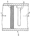
図1は、本発明の実施の形態1にかかる脱臭素子の一例の断面図である。
第1の脱臭素子5は、基材1、および前記基材1上に設けられた脱臭材料層からなり、前記脱臭材料層は、結着剤2、金属酸化物3および光触媒4を含んでいる。基材1は、不織布のような繊維状であっても板状のものであってもよく、特に、表面積の大きなハニカム形状が好ましい。結着剤2は、金属酸化物3や光触媒4と、基材1との密着性を向上させるために用いられる。
【0014】
次に、第1の脱臭素子5の製造方法を説明する。
まず、金属水酸化物および液状成分からなる分散液を調製する。液状成分には、金属水酸化物に加えて、さらに、結着剤2またはその原料を分散または溶解させることが好ましい。この場合、結着剤2は、金属水酸化物から金属酸化物3を形成する際に、高温条件で加熱されることになるため、無機材料であることが好ましい。
【0015】
無機材料からなる結着剤2には、例えば、アルカリ−ケイ酸塩系ガラス、シリカ、アルミナなどを用いることが好ましい。また、アルカリ−ケイ酸塩系ガラスは、液状成分中で、水ガラスを形成していることが好ましく、シリカやアルミナは、コロイド粒子として液状成分中に分散していることが好ましい。
【0016】
液状成分には、金属水酸化物を均一に分散させることができるものを特に限定なく用いることができるが、取り扱いが容易であることなどから、水を用いることが好ましい。
【0017】
液状成分に分散または溶解させる結着剤2の量は、金属水酸化物100重量部あたり1〜100重量部であることが好ましい。結着剤2の量が多すぎると、金属水酸化物より得られる金属酸化物の吸着効果が十分に得られなくなり、少なすぎると、金属酸化物3や光触媒4と、基材1との密着性を向上させる効果が十分に得られない。
【0018】
次に、上述の分散液に、基材1を浸漬することにより、基材1上に分散液の塗膜を形成する。そして、基材1とともに分散液の塗膜を、高温加熱炉等で所定の温度で加熱し、金属水酸化物を金属酸化物3に変化させることにより、金属酸化物3からなる担体層を形成する。
【0019】
なお、結着剤2は、上述の分散液に含ませる以外に、どのような方法で基材1上に付与してもよい。例えば、光触媒4を基材1上に付与するときに用いる原料溶液または分散液中に、結着剤を添加することもできる。
【0020】
ハニカム形状を有する基材1には、金属酸化物3および光触媒4により被覆される面積が大きく、かつ、耐熱性にも優れることから、多孔質セラミックス、セラミックス繊維あるいは金属またはそれらの混合物からなることが好ましい。また、金属水酸化物から得られる金属酸化物3の形状は、薄膜状であっても粒状であってもよい。
【0021】
金属水酸化物としては、水酸化マグネシウム、水酸化銅、水酸化ニッケル、水酸化鉛、水酸化カルシウム、水酸化アルミニウム、水酸化亜鉛、水酸化ストロンチウムおよび水酸化コバルトなどがあり、特に水酸化マグネシウムがより好ましい。
【0022】
金属水酸化物から金属酸化物を得るための加熱温度は、金属水酸化物の種類によって異なるが、150〜700℃程度であり、特に、500℃以上であることがより好ましい。また、加熱は、空気中または酸素中で行うことが好ましい。
【0023】
光触媒4としては、酸化チタン、酸化タングステン、酸化ジルコニウム、酸化亜鉛、チタン酸ストロンチウムなどが好ましく、特に酸化チタンがより好ましい。また上述した第1の脱臭素子5の構成は、基材1上に結着剤2と金属酸化物3からなる担体層が形成され、その層上に光触媒4が担持されているが、光触媒4は基材1上に形成された結着剤2と金属酸化物3からなる担体層中に入り込んだ状態であってもよい。
【0024】
次に、光触媒を脱臭素子に担持する方法の詳細を以下に説明する。
まず、光触媒の原料溶液を用いる方法について説明する。
光触媒の原料には、チタンテトライソプロポキシドなどの金属アルコキシド化合物、光触媒の微粒子を分散させた懸濁液などを用いることができる。原料溶液は、ジエタノールアミンなどの塩基性物質や硝酸などの酸性物質を含むアルコール、水などの溶媒に、光触媒の原料を溶解させて調製する。
【0025】
次いで、得られた原料溶液に、担体層を有する基材を浸漬し、400〜600℃で加熱する。加熱により、金属アルコキシドの加水分解反応が進行し、光触媒となる酸化物薄膜が、担体層上に形成される。金属アルコキシドの加水分解反応を利用する方法はゾル・ゲル法と呼ばれる。なお、光触媒の原料溶液には、金属水酸化物が分散されていてもよい。
【0026】
次に、光触媒微粒子の分散液を用いる方法について説明する。
まず、粒径が数μmから数nmの光触媒微粒子を分散媒と混合して、光触媒の分散液を調製する。この分散液に、担体層を有する基材を浸漬し、100〜600℃で加熱して、担体層の微細孔内に光触媒微粒子を担持する。なお、光触媒の分散液には、金属水酸化物が分散されていてもよい。また、分散媒には、加熱操作によって完全に揮散してしまうものを用いても良いが、結着剤を含む分散媒を用いてもよい。例えば、シリカのコロイド溶液などを用いることが好ましい。
【0027】
上記の他に、CVDなどの気相成膜法、(NH4)2TiF6(ヘキサフルオロチタン酸アンモニウム)などを出発原料とする液相析出法(LPD;Liquid Phase Deposition)などを採用して、光触媒を担体層に担持することもできる。
【0028】
担体層に担持させる光触媒の量は、光触媒が担体に十分固定され、光照射に伴い発現される光触媒効果が確認される範囲内であれば、特に限定されることはない。また、基材上に形成された脱臭材料層の厚さは、数十〜数百μmであることが好ましい。脱臭材料層の厚さが薄すぎると、脱臭効果が不十分となり、厚すぎると、表層部だけが脱臭効果を発揮し、下層部の材料が有効に用いられないこととなる。
【0029】
図2は、図1の脱臭素子を備えた脱臭装置の構成の一例を示す部分断面図である。
第1の脱臭装置9は、第1の脱臭素子5と、光源6とを備えている。光源6は、第1の脱臭素子5に担持された光触媒に光を照射するものである。光触媒は、光が照射されると活性化し、光触媒に接触した臭気物質を酸化分解して、臭気物質を除去する。光源6としては、酸化チタンなどの光触媒を活性化するのに有効な波長である380nm以下に出力ピークを有する紫外線ランプが好ましく、熱陰極管方式でも冷陰極管方式でもよい。また、図中矢印は、空気の流れを示しており、臭気物質を含む空気7は、第1の脱臭装置9内部を通過すると、臭気物質が除去されて、清浄な空気8が第1の脱臭装置9の外部に放出される。
【0030】
上述のような本実施の形態1にかかる脱臭素子においては、光触媒による臭気物質の分解を行うときに、金属水酸化物を原料として作製した金属酸化物が助触媒的な効果を発現していると考えられ、光触媒だけを用いたときよりも、臭気物質の分解効率が向上する。つまり、金属酸化物が臭気物質と吸着することによって、臭気物質の分解反応の活性化エネルギーが低下し、光触媒による臭気物質の酸化分解反応の効率が向上するものと考えられる。
【0031】
本発明においては、金属水酸化物の種類によって、基材表面の性状を酸性あるいは塩基性に設計することが可能である。したがって、脱臭対象となる臭気物質の種類によって、脱臭素子の吸着性能を調製することができる。例えば、金属水酸化物の金属元素をMg、Ca、Zn、AlおよびNiなどの電気陰性度の小さい金属元素とすることによって、金属酸化物を形成した脱臭素子の表面は、塩基性を示すことになる。これに対し、光触媒である酸化チタンは、酸性の固体表面を有することから、脱臭素子に酸性および塩基性の両方の特性を付与することができる。このように作製された脱臭素子によれば、硫化水素、メチルメルカプタンなどの酸性臭気ガスや、アンモニア、トリメチルアミンなどの塩基性臭気ガスの両者を高効率で吸着除去することができる。
【0032】
また、基材上に金属酸化物と光触媒を別々の工程で担持することにより、光触媒の粒子成長などを抑制するとともに、それぞれの材料に適した温度条件で担持することができる。また、光触媒を脱臭素子の最表面に担持させることができる。したがって、光触媒が金属酸化物で埋もれてしまうことがなく、光触媒の効果を有効に発揮させることができる。
さらに、光照射時における臭気物質吸着効果のみならず、光未照射時においても、金属酸化物が高い臭気物質吸着能力を示すことから、光源の点灯時間を短縮させることができる。また、光触媒だけを用いた場合と比べて、使用電力量が少なくて済み、効率よく臭気物質の除去を行うことができる。
【0033】
実施の形態2
図3は、本発明の実施の形態2にかかる脱臭素子の一例の断面図である。
図3より、第2の脱臭素子11は、基材1、および前記基材1上に設けられた脱臭材料層からなり、前記脱臭材料層は、結着剤2、金属酸化物3、吸着剤10および光触媒4を含んでいる。結着剤2は、金属酸化物3、吸着剤10および光触媒4と、基材1との密着性を向上させるために用いられる。結着剤2は、例えば、金属水酸化物の分散液中、あるいは光触媒4を基材1上に付与するときに用いる原料溶液もしくは分散液中に添加しておくことが好ましい。
第2の脱臭素子11は、吸着剤10を用いること以外は、上述した第1の脱臭素子5と同様の方法で製造することができる。
また、液状成分に分散または溶解させる吸着剤10の量は、金属水酸化物100重量部あたり1〜100重量部であることが好ましい。この吸着剤10は、金属水酸化物から金属酸化物を形成する際に高温条件で加熱されることから、活性炭、ゼオライト、シリカ、アルミナなどの無機材料であることが好ましく、特に、ゼオライトとシリカがより好ましい。
【0034】
上述した第2の脱臭素子11の構成は、基材1上に結着剤2、吸着剤10および金属酸化物3からなる担体層が形成され、その層上に光触媒4が担持されている。しかし、光触媒4は、基材1上に形成された結着剤2、吸着剤10および金属酸化物3からなる担体層中に入り込んだ状態であってもよい。また、本発明の第2の脱臭素子11は、前述した図2に示すように、さらに光源を備えて脱臭装置を構成することができる。
【0035】
本発明においては、吸着剤を担持させたことから、臭気物質に対する吸着能力が増加し、臭気物質の除去効果を向上させることができる。したがって、臭気物質の濃度を低下させることにより、光触媒が臭気物質を分解除去する負担を軽減させ、光触媒に照射する光源の点灯時間を短縮させることができる。
また、吸着剤および金属酸化物の表面の性状がそれぞれ異なることから、基材上に、吸着剤と金属酸化物を担持させたときに担体層の表面に凹凸が形成される。したがって、このような担体層上に光触媒を担持させたとき、脱臭材料層の表面積が、さらに増大し、多種多様な表面性状を有する臭気物質を捕捉することができる。また、吸着剤を担持したことにより、光触媒の近傍に臭気物質を捕捉させる状態を形成するので、効率よく臭気物質の分解を行うことができる。
【0036】
ここで、金属水酸化物と吸着剤を分散させる液状成分は、金属水酸化物や吸着剤を溶解するものであっても、あるいは溶解しないものであってもよく、金属水酸化物または吸着剤と化学反応を起こさないものであれば特に限定されることはない。また、金属水酸化物から金属酸化物を形成する際に、加熱操作を行うことから、液状成分は、水または水との混合溶液が好ましく、特に、基材上の表面を凹凸にして、表面積を増大させるために、コロイダルシリカを含んだ水溶液を用いることが好ましい。
【0037】
実施の形態3
図4は、本発明の実施の形態3にかかる脱臭装置の一例の構成図である。
図4より、第2の脱臭装置12は、臭気物質を含む空気7の吸込口側に設けた加熱手段13と、臭気物質が除去された空気8の吹出口側に設けた光源6と、前記加熱手段13および光源6の間に設けた第1の脱臭素子5とを含んでいる。加熱手段13は、第1の脱臭素子5の表面を加熱するものであり、ヒーター線などによる直接加熱方式であっても、他の熱源から熱を伝える間接加熱方式であってもよく、特に限定されることはない。また、この加熱手段13による加熱温度は150℃以上に設定できることが好ましい。
【0038】
本発明においては、加熱手段をさらに備えたことから、脱臭素子表面に吸着された水分子や臭気物質の分子を加熱除去させることができる。したがって、臭気物質の濃度を低下させることにより、光触媒が臭気物質を分解除去する負担を軽減させ、光触媒に照射する光源の点灯時間を短縮させることができる。また加熱手段は、金属酸化物および光触媒表面の被毒を解消させることができ、脱臭素子を長期間にわたって、使用することができる。
本発明の脱臭装置は、第1の脱臭素子5を含んだ構成を例に取り説明したが、第1の脱臭素子5に代えて、第2の脱臭素子11を含んだ構成としてもよい。この構成により、臭気物質の吸着除去能力が向上し、光触媒の効果を発現させるために必要な光源の点灯時間を短縮させることが可能となる。
【0039】
次に、本発明の脱臭装置を冷凍サイクル装置に備えた例について、以下に説明する。ここで、冷凍サイクル装置は、冷媒、冷媒が循環する配管、および循環する冷媒の流量を調節する流量調節器を有する。この流量調節器には、圧縮機、凝縮器、蒸発器、電磁膨張弁およびキャピラリーチューブなどがある。
【0040】
実施の形態4
図5は、本発明の実施の形態4にかかる脱臭素子を備えた冷凍サイクル装置の一例の要部面図である。
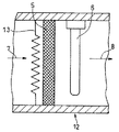
図5より、冷蔵庫本体14は、食品などを貯蔵する冷蔵室15、冷蔵室扉28および冷蔵室15の背面と冷蔵庫本体14との隙間に設けられた通風路16を備えている。この通風路16には、冷気循環用ファン20、第2の脱臭素子11、第2の脱臭素子11の表面に光を照射する光源6および配管中を循環する冷媒が気化することによって冷却効果を発現するエバポレータ17が設置されている。また、冷蔵室15と通風路16を隔てる側壁には、通風路16から冷蔵室15へ冷気を送る冷気吹出口18と、冷蔵室15から通風路16へ冷気を送る冷気吸込口19とが設けられている。図中矢印21は冷蔵庫本体14内部の空気の流れを示している。
【0041】
冷蔵室15内部に保存されている食品からは、種々の臭気物質が放出される。この冷蔵庫本体14内部の空気は、冷気循環用ファン20の稼動とともに、冷蔵室15から冷気吸込口19を通して、通風路16に導かれる。そして、冷気吹出口18を通して、再び冷蔵室15内部へと移動する。このとき、冷気吸込口19から通風路16内に導かれた臭気物質は、第2の脱臭素子11を通過したときに臭気物質が除去されて、清浄な空気が冷気吹出口18を通して、再び冷蔵室15へ放出される。
【0042】
本発明においては、通風路内に脱臭素子と、光源とを備えたので、冷蔵室から発生する、酸性あるいは塩基性の特性を示す種々の臭気物質を除去することができる。さらに、光源を用いて光触媒による脱臭素子表面の清浄化を行うようにしたので、長期間に渡って優れた脱臭機能を有する冷凍サイクル装置を提供することができる。したがって、臭気物質が、冷蔵室に貯蔵している食品に害を与える影響をなくすことができ、さらに、長期間使用した際にも臭気物質が冷蔵室内に滞留することのない冷凍サイクル装置を提供することができる。
【0043】
実施の形態5
図6は、本発明の実施の形態5にかかる脱臭素子を備えた冷凍サイクル装置の一例の要部断面図である。
図6より、空調機器本体22は、空気の吸入口を形成する前面パネル23、粒径の大きな固形物質を捕らえるプレフィルター24、第2の脱臭素子11、第2の脱臭素子11表面に光を照射する光源6、第2の脱臭素子11の表面を加熱する加熱手段13、熱交換器25、送風ファン26および風向板27が設置されている。また図中矢印21は空気の流れを示している。
【0044】
室内空気には、有害なホルムアルデヒドやトルエンなどの有機溶剤、食品からの臭い、ペットのし尿臭など、種々の臭気物質が含まれている。この空調機器本体22内部の空気の流れは、送風ファン26の稼動とともに、室内空気が前面パネル23を通して空調機器本体22内部に導かれる。空調機器本体22内部に導かれた室内空気は、プレフィルター24を通過することによって粒径の大きな塵やほこりといった固形物質が取り除かれる。プレフィルター24を通過した室内空気は第2の脱臭素子11を通過することにより臭気物質が除去される。そして、臭気物質が除かれた清浄な空気は熱交換器25、および送風ファン26を経て風向板27によって風向を制御されながら空調機器本体22外部へ放出される。
【0045】
本発明においては、空調機器内部に脱臭素子、光源および加熱手段を備えたので、脱臭素子に吸着された水分子や臭気物質の分子が加熱手段により加熱除去させることができる。したがって、臭気物質の濃度を低下させることにより、光触媒が臭気物質を分解除去する負担を軽減させ、光触媒に照射する光源の点灯時間を短縮させることができる。
【0046】
【実施例】
以下、本発明の実施例を説明する。
《実施例1》
水酸化マグネシウム粉末2gをコロイダルシリカ水溶液(スノーテックス30Ml;日産化学工業(株)製)1Lにスターラーにて攪拌しながら添加し、均一に分散するまで攪拌を続けて分散液を調製した。このとき、コロイダルシリカ水溶液に含まれるシリカの量は、約30wt%であった。続いて、一定時間経過後、セラミックス繊維にて構成された基材(ハニクル;ニチアス(株)製)を前記分散液に浸漬し、引き上げて、高温加熱炉にて550℃で30分間加熱して担体層を作製した。加熱後、チタニアゾル水溶液(STS−01;石原テクノ(株)製)に前記担体層を浸漬し、チタニアゾル水溶液から取り出し時に滴下してくる余分な溶液を窒素ガスブローにより除去した後、恒温炉にて200℃で30分間加熱した。このように作製された脱臭素子は、担体層が形成された基材に対して、光触媒材料が400mg担持されていた。次に、この脱臭素子を用いて臭気物質の除去能力を評価した。
【0047】
除去する臭気物質として、メチルメルカプタン(CH3SH)ガスを選定した。6.7Lの容積を持つ容器内に、前記脱臭素子と、光触媒を活性化させる際の光源として用いる、出力9Wのブラックライトランプ(PL−S9W/08;Philips社製)を設置した。そして、容器内を真空ポンプで排気後、乾燥空気に対する濃度が10ppmとなるように調整されたメチルメルカプタンガスを容器内に導入した。
【0048】
まず、容器内に設置した光源を照射しないで、60分間経過後のメチルメルカプタンガスの濃度を測定したところ、0.1ppmであった。メチルメルカプタンガスは飽和傾向を示すことなく、検出限界の濃度まで低下していた。次に、メチルメルカプタンガスを導入開始後、連続的に光源を照射した場合では、ガス導入後数分にして、検出限界以下の濃度までメチルメルカプタンガスを除去することが確認された。
【0049】
《比較例1》
実施例1と同じセラミックス繊維で構成した基材を、金属水酸化物を含まない前記コロイダルシリカ水溶液に浸漬し、高温加熱炉にて550℃で30分間加熱して担体層を作製した。加熱後、前記チタニアゾル水溶液に前記担体層を浸漬し、チタニアゾル水溶液から取り出し時に滴下してくる余分な溶液を窒素ガスブローにより除去した後、恒温炉にて200℃で30分間加熱した。
このように作製された脱臭素子を用いて、実施例1と同様に、臭気物質としてメチルメルカプタンガス10ppmを導入し、臭気物質の除去能力を評価した。まず、容器内に設置した光源を照射しないで、60分間経過後のメチルメルカプタンガスの濃度を測定したところ、1ppmであった。しかし、その後、光源を照射すると、メチルメルカプタンガスの急速な濃度低下が確認された。
【0050】
《比較例2》
実施例1と同じセラミックス繊維で構成した基材を、水酸化マグネシウム粉末2gを前記コロイダルシリカ水溶液1Lに分散させた分散液に浸漬し、恒温炉にて100℃で30分間乾燥させ、水酸化マグネシウムを金属水酸化物のまま担持させた担体層を作製した。乾燥後、前記チタニアゾル水溶液に前記担体層を浸漬し、チタニアゾル水溶液から取り出し時に滴下してくる余分な溶液を窒素ガスブローにより除去した後、恒温炉にて200℃で30分間加熱した。
このように作製された脱臭素子を用いて、実施例1と同様に、臭気物質としてメチルメルカプタンガス10ppmを導入し、臭気物質の除去能力を評価した。まず、容器内に設置した光源を照射しないで、60分間経過後のメチルメルカプタンガスの濃度を測定したところ、8ppmであった。つまり、メチルメルカプタンガスはほとんど除去されずに残留していることが確認された。しかし、その後、光源を照射すると、メチルメルカプタンガスの急速な濃度低下が確認された。
【0051】
《実施例2》
水酸化マグネシウム粉末2gと疎水性ゼオライト(アブセンツ2000;ユニオン昭和(株)製)2gコロイダルシリカ(スノーテックスPS−M;日産化学工業(株)製)1Lをスターラーにて撹拌しながら添加し、均一に分散するまで撹拌を続けて分散液を調製した。そして、この分散液を基材(ハニクル;ニチアス(株)製)に塗布した。ここで、基材に分散液を塗布する方法は、浸漬方式、滴下方式、あるいはスプレー方式などいずれの方法でもよい。続いて、分散液を基材上に塗布後、高温加熱炉にて500℃で30分間加熱し、吸着剤と金属酸化物の多孔質薄膜を基材表面上に形成した担体層を作製した。そして、この担体層を、チタニアゾル水溶液(STS−01;石原テクノ(株)製)に浸漬し、チタニアゾル水溶液から取り出し時に滴下してくる余分な溶液を窒素ガスブローにより除去した後、恒温炉にて200℃で30分間加熱した。このように作製された脱臭素子は、担体層が形成された基材に対して、光触媒が45mg担持されていた。次に、この脱臭素子を用いて臭気物質の除去能力を評価した。
【0052】
除去する臭気物質として、アセトアルデヒド(CH3CHO)ガスを選定した。10Lの容積を持つ容器内に、前記脱臭素子と、光触媒を活性化させる際の光源として、冷陰極管タイプのUVランプ(K−CE150−26−HBA;ウエスト電器(株)製)を設置した。そして、容器内を真空ポンプで排気後、乾燥空気に対する濃度が100ppmとなるように調整されたアセトアルデヒドガスを容器内に導入した。
まず、容器内に設置した光源を照射しないで、20分間経過後のアセトアルデヒドガスの濃度を測定したところ、1ppmであった。続いて、この濃度測定後、光源を照射すると、さらに効率よくアセトアルデヒドガスが除去されることが確認された。
【0053】
吸着剤を含まないこと以外は実施例2を全て同じ材料で作製した脱臭素子を用いて、実施例2と同様に臭気物質の除去能力を評価した。
まず容器内に設置した光源を照射しないで、20分間経過後のアセトアルデヒドガスの濃度を測定したところ、10ppmであった。つまり、アセトアルデヒドガスはあまり除去されずにほとんど残留していることが確認された。
【0054】
《実施例3》
容積10Lの容器内に、実施例1と同様の脱臭素子と、脱臭素子を加熱するための加熱手段と、脱臭素子に光を照射する光源(出力9Wのブラックライトランプ(PL−S9W/08;Philips社製))とを設置した。
【0055】
まず、除去する臭気物質としてメチルメルカプタンガスを用い、光を照射しないときの臭気物質の残留濃度を測定した。
容器内の空気を排気後、乾燥空気に対する濃度が10ppmとなるように調整されたメチルメルカプタンガスを容器内に導入した。そして、容器内に繰り返しメチルメルカプタンガスを導入していくと、容器内におけるメチルメルカプタンガスの減少挙動は経過時間とともに鈍化し、メチルメルカプタンガスの導入開始後1ヶ月経過時において、ガス導入から60分経過後における容器内のメチルメルカプタンガスの濃度は1ppm(初期能力値0.1ppm)まで上昇していた。次に、この脱臭素子を加熱手段によって150℃で30分間加熱した。そして、加熱終了後に再びメチルメルカプタンガスの濃度が10ppmとなるように容器内に導入したところ、60分経過後の残留濃度は初期能力値(0.1ppm)まで低下していた。
【0056】
次に、除去する臭気物質としてアセトアルデヒドガスを用い、光を照射後、加熱手段を用いたときの臭気物質の残留濃度を測定した。
容器内の空気を排気後、乾燥空気に対する濃度が100ppmとなるように調整されたアセトアルデヒドガスを容器内に導入した。そして、容器内に繰り返しアセトアルデヒドガスを導入していくと、アセトアルデヒドガスを導入開始後1ヶ月経過時において、ガス導入から60分経過後における容器内のアセトアルデヒドガスの濃度は3ppm(初期能力値1ppm)であった。次に、この脱臭素子を加熱手段で加熱すると、アセトアルデヒドガスの濃度は初期能力値(1ppm)まで低下し、脱臭素子作製時のアセトアルデヒドガスの脱臭除去能力まで回復していた。
【0057】
《実施例4》
容積10Lの容器内に、実施例2と同様の脱臭素子と、脱臭素子を加熱するための加熱手段と、脱臭素子に光を照射する光源(出力9Wのブラックライトランプ(PL−S9W/08;Philips社製))とを設置した。
【0058】
まず、除去する臭気物質としてエチルアルコールガスを用い、光を照射しないときの臭気物質の残留濃度を測定した。
容器内の空気を排気後、乾燥空気に対する濃度が10ppmとなるように調整されたエチルアルコールガスを容器内に導入した。そして、容器内に繰り返しエチルアルコールガスを導入していくと、容器内におけるエチルアルコールガスの減少挙動は経過時間とともに鈍化し、エチルアルコールガスの導入開始後1ヶ月経過時において、ガス導入から60分経過後における容器内のエチルアルコールガスの濃度は3ppm(初期能力値0.1ppm)まで上昇していた。次に、この脱臭素子を加熱手段によって150℃で30分間加熱した。そして、加熱終了後に再びエチルアルコールガスの濃度が10ppmとなるように容器内に導入したところ、60分経過後の残留濃度は初期能力値(0.1ppm)まで低下していた。
【0059】
次に、除去する臭気物質としてアセトアルデヒドガスを用い、光を照射後、加熱手段を用いたときの臭気物質の残留濃度を測定した。
容器内の空気を排気後、乾燥空気に対する濃度が100ppmとなるように調整されたアセトアルデヒドガスを容器内に導入した。そして、容器内に繰り返しアセトアルデヒドガスを導入していくと、アセトアルデヒドガス導入開始後1ヶ月経過時において、ガス導入から60分経過後における容器内のアセトアルデヒドガスの濃度は1ppm(初期能力値0.1ppm)であった。次に、この脱臭素子を加熱手段によって200℃で30分間加熱すると、アセトアルデヒドガスの濃度は0.1ppmまで低下した。したがって、脱臭素子は、加熱手段によって、機能が再生され初期能力値の濃度まで再びアセトアルデヒドガスを除去することが確認された。
【0060】
【発明の効果】
以上のように本発明によれば、酸性あるいは塩基性の特性を示すいずれの臭気ガスに対しても、優れた脱臭効果を示す脱臭素子を提供することが可能となり、この脱臭素子を冷凍サイクル装置に備えることにより、長期間にわたって脱臭効果を良好に有することができる。
【図面の簡単な説明】
【図1】本発明の実施の形態1にかかる脱臭素子の一例の断面図である。
【図2】同脱臭素子を備えた脱臭装置の構成の一例を示す部分断面図である。
【図3】本発明の実施の形態2にかかる脱臭素子の一例の断面図である。
【図4】本発明の実施の形態3にかかる脱臭装置の構成の一例を示す部分断面図である。
【図5】本発明の実施の形態4にかかる脱臭素子を備えた冷凍サイクル装置の一例の要部断面図である。
【図6】本発明の実施の形態5にかかる脱臭素子を備えた冷凍サイクル装置の一例の横断面図である。
【符号の説明】
1 基材
2 結着剤
3 金属酸化物
4 光触媒
5 第1の脱臭素子
6 光源
7 臭気物質を含む空気
8 臭気物質が除去された空気
9 第1の脱臭装置
10 吸着剤
11 第2の脱臭素子
12 第2の脱臭装置
13 加熱手段
14 冷蔵庫本体
15 冷蔵室
16 通風路
17 エバポレータ
18 冷気吹出口
19 冷気吸込口
20 冷気循環用ファン
21 空気の流れ
22 空調機器本体
23 前面パネル
24 プレフィルター
25 熱交換器
26 送風ファン
27 風向板
28 冷蔵室扉[0001]
TECHNICAL FIELD OF THE INVENTION
TECHNICAL FIELD The present invention relates to a deodorizing element useful for removing odorous substances from air, a method for producing the same, and a refrigeration cycle apparatus using the deodorizing element.
[0002]
[Prior art]
Odorous substances emitting foul odors are generated from various sources, for example, everyday living environments, facilities such as factories, human waste treatment plants, and garbage disposal plants, and pose a problem as a cause of bad odor pollution. Examples of the odorants include ammonia, nitrogen-containing compounds such as amines (such as trimethylamine and triethylamine), hydrogen sulfide, sulfur-containing compounds such as mercaptans (such as methyl mercaptan), aldehydes (such as formaldehyde and acetaldehyde), and lower fatty acids. Many compounds are known, such as (formic acid, acetic acid, valeric acid, etc.).
[0003]
Activated carbon is widely used for deodorizing such odorous substances. However, activated carbon has a small adsorption capacity for nitrogen-containing compounds such as ammonia and sulfur-containing compounds such as hydrogen sulfide. Further, there is a problem that various odorous substances cannot be adsorbed even when only activated carbon is used. Therefore, an adsorbent in which activated carbon carries a halogen compound, a metal ion, an acid, an alkali, and the like has been proposed. However, even if these adsorbents are used, they have not yet achieved sufficient deodorizing ability.
In addition, zeolite, silica gel, activated alumina and the like are also used as deodorizing elements. However, they have a low adsorption capacity for odorous substances, and the equilibrium adsorption concentration, which is an index of the deodorization ability, increases with an increase in the amount of adsorption, so that the odor removal becomes insufficient with the elapse of the treatment time.
[0004]
In order to improve the limit of the deodorizing ability, there is a deodorizing method using a photocatalyst such as titanium oxide. In this method, the odorous substance adsorbed on the photocatalyst surface is oxidized and decomposed by irradiation with light such as ultraviolet rays. Therefore, as long as the photocatalyst has a sufficient reaction surface and continues irradiation with light, it has a high processing ability. However, in the deodorizing treatment method using a photocatalyst, when the light irradiation is not performed, the odorous substance is not oxidized and decomposed. That is, if the photocatalyst is not always irradiated with light, a deodorizing effect cannot be expected.
Then, as a deodorizing element which improves such a problem, there is an element obtained by sintering a mixture of an adsorbent and a photocatalyst (for example, see Patent Document 1).
[0005]
[Patent Document 1]
Japanese Patent No. 2138415 (Claim 1)
[0006]
[Problems to be solved by the invention]
However, the deodorizing element specifically proposed uses titanium oxide which is an acidic solid catalyst as a photocatalyst, and the adsorbent such as zeolite and silica used together has an acidic solid surface. In other words, although the deodorizing element using the photocatalyst is excellent in the adsorptivity to the basic substance, it has a problem that it is difficult to expect the active adsorption and removal of the acidic substance. Adsorbents made of alumina are expected to adsorb acidic substances, but alumina has a lower electronegativity than silica or titanium oxide, and the material itself increases as the ratio of alumina in the deodorizing element increases. Is increased in hydrophilicity. Then, the amount of moisture adsorbed by the deodorizing element increases, and there is a problem that the amount of adsorbing odorous substances that must be adsorbed decreases.
[0007]
Therefore, when the above-mentioned deodorizing element is mounted on various refrigeration cycle devices such as air conditioners and refrigerators, the performance of the deodorizing element is reduced by long-term use, or an odorous substance that cannot be completely adsorbed causes further odor. Or problems.
[0008]
An object of the present invention is to effectively perform a decomposition reaction of an odorous substance by a photocatalyst in order to solve the above-described problems. The present invention also provides a deodorizing element having good deodorizing properties for both odorous substances such as acidic substances (eg, methyl mercaptan, dimethyl sulfide, etc.) and basic substances (eg, ammonia, trimethylamine, etc.). Aim. Still another object of the present invention is to provide a refrigeration cycle apparatus using a deodorizing element capable of maintaining a deodorizing effect for a long period of time.
[0009]
[Means for Solving the Problems]
The present invention comprises a substrate having a honeycomb shape and a deodorizing material layer provided on the substrate, wherein the deodorizing material layer comprises a metal oxide and a photocatalyst, wherein the metal oxide is a metal hydroxide and Provided is a deodorizing element which is formed by applying a dispersion composed of a liquid component on the substrate and heating the dispersion.
[0010]
Preferably, the metal hydroxide is magnesium hydroxide. It is preferable that the deodorizing material layer further includes an adsorbent that captures odorous substances. The photocatalyst is preferably titanium oxide. The substrate is preferably made of a porous ceramic, ceramic fiber or metal material. The dispersion preferably further includes colloidal particles of silica. The adsorbent is preferably at least one selected from the group consisting of activated carbon, zeolite and silica.
[0011]
Further, the present invention is provided with a main body having a ventilation path, a refrigerant for cooling the inside of the ventilation path, a pipe for circulating the refrigerant, a flow rate regulator for the refrigerant circulating in the pipe, and provided in the ventilation path. A refrigeration cycle device including a deodorizing element, wherein the deodorizing element includes a substrate having a honeycomb shape and a deodorizing material layer provided on the substrate, and the deodorizing material layer includes a metal oxide and a photocatalyst. And a refrigeration cycle apparatus wherein the metal oxide is formed by applying a dispersion liquid composed of a metal hydroxide and a liquid component on the substrate and heating the dispersion.
It is preferable that the refrigeration cycle apparatus further includes a light source for irradiating the deodorizing element with light. Further, it is preferable that a heating means for heating the deodorizing element is provided. The heating means preferably has a function of heating the deodorizing element at 150 ° C. or higher.
[0012]
Further, the present invention provides (a) a step of forming a carrier layer composed of a metal oxide by applying a dispersion liquid composed of a metal hydroxide and a liquid component on a substrate having a honeycomb shape and heating the dispersion. (B) supporting a photocatalyst on the carrier layer.
The step (a) is preferably a step of forming the carrier layer by heating a coating film of the dispersion applied on the base material at 500 ° C. or higher in air.
[0013]
BEST MODE FOR CARRYING OUT THE INVENTION
Embodiments of the present invention will be described below with reference to the drawings.
FIG. 1 is a sectional view of an example of the deodorizing element according to the first embodiment of the present invention.
The
[0014]
Next, a method for manufacturing the
First, a dispersion comprising a metal hydroxide and a liquid component is prepared. It is preferable to disperse or dissolve the binder 2 or its raw material in addition to the metal hydroxide in the liquid component. In this case, the binder 2 is heated under high-temperature conditions when forming the metal oxide 3 from the metal hydroxide, and thus is preferably an inorganic material.
[0015]
As the binder 2 made of an inorganic material, for example, it is preferable to use, for example, an alkali-silicate glass, silica, or alumina. Further, the alkali-silicate glass preferably forms water glass in the liquid component, and silica and alumina are preferably dispersed in the liquid component as colloid particles.
[0016]
As the liquid component, those capable of uniformly dispersing the metal hydroxide can be used without any particular limitation. However, it is preferable to use water because of easy handling.
[0017]
The amount of the binder 2 to be dispersed or dissolved in the liquid component is preferably 1 to 100 parts by weight per 100 parts by weight of the metal hydroxide. If the amount of the binder 2 is too large, the effect of adsorbing the metal oxide obtained from the metal hydroxide will not be sufficiently obtained, and if the amount is too small, the adhesion between the metal oxide 3 or the photocatalyst 4 and the
[0018]
Next, a coating film of the dispersion is formed on the
[0019]
The binder 2 may be provided on the
[0020]
The
[0021]
Examples of metal hydroxides include magnesium hydroxide, copper hydroxide, nickel hydroxide, lead hydroxide, calcium hydroxide, aluminum hydroxide, zinc hydroxide, strontium hydroxide, and cobalt hydroxide. Is more preferred.
[0022]
The heating temperature for obtaining the metal oxide from the metal hydroxide varies depending on the type of the metal hydroxide, but is about 150 to 700 ° C, particularly preferably 500 ° C or more. The heating is preferably performed in air or oxygen.
[0023]
As the photocatalyst 4, titanium oxide, tungsten oxide, zirconium oxide, zinc oxide, strontium titanate and the like are preferable, and titanium oxide is particularly preferable. Further, in the configuration of the
[0024]
Next, details of a method of supporting the photocatalyst on the deodorizing element will be described below.
First, a method using a photocatalyst raw material solution will be described.
As a raw material of the photocatalyst, a metal alkoxide compound such as titanium tetraisopropoxide, a suspension in which fine particles of the photocatalyst are dispersed, or the like can be used. The raw material solution is prepared by dissolving the raw material of the photocatalyst in a solvent such as alcohol or water containing a basic substance such as diethanolamine or an acidic substance such as nitric acid.
[0025]
Next, the substrate having the carrier layer is immersed in the obtained raw material solution and heated at 400 to 600 ° C. By the heating, the hydrolysis reaction of the metal alkoxide proceeds, and an oxide thin film serving as a photocatalyst is formed on the carrier layer. A method utilizing a hydrolysis reaction of a metal alkoxide is called a sol-gel method. Note that a metal hydroxide may be dispersed in the raw material solution of the photocatalyst.
[0026]
Next, a method using a dispersion of photocatalyst fine particles will be described.
First, photocatalyst fine particles having a particle diameter of several μm to several nm are mixed with a dispersion medium to prepare a photocatalyst dispersion liquid. A substrate having a carrier layer is immersed in the dispersion and heated at 100 to 600 ° C. to support photocatalyst fine particles in the fine pores of the carrier layer. The metal hydroxide may be dispersed in the dispersion of the photocatalyst. Further, as the dispersion medium, one that completely volatilizes by a heating operation may be used, or a dispersion medium containing a binder may be used. For example, it is preferable to use a colloidal solution of silica or the like.
[0027]
In addition to the above, a vapor deposition method such as CVD, (NH 4 ) 2 TiF 6 The photocatalyst can be supported on the carrier layer by employing a liquid phase deposition method (LPD; Liquid Phase Deposition) using (hexafluorofluorotitanate) or the like as a starting material.
[0028]
The amount of the photocatalyst to be supported on the carrier layer is not particularly limited as long as the photocatalyst is sufficiently fixed to the carrier and a photocatalytic effect developed with light irradiation is confirmed. Further, the thickness of the deodorizing material layer formed on the base material is preferably several tens to several hundreds μm. If the thickness of the deodorizing material layer is too thin, the deodorizing effect becomes insufficient. If it is too thick, only the surface layer exerts the deodorizing effect, and the material of the lower layer cannot be used effectively.
[0029]
FIG. 2 is a partial cross-sectional view showing an example of a configuration of a deodorizing device including the deodorizing element of FIG.
The
[0030]
In the deodorizing element according to the first embodiment as described above, when the odorant is decomposed by the photocatalyst, the metal oxide produced using the metal hydroxide as a raw material has a cocatalytic effect. It is considered that the decomposition efficiency of the odorous substance is improved as compared with the case where only the photocatalyst is used. That is, it is considered that the activation energy of the decomposition reaction of the odor substance is reduced by the adsorption of the metal oxide with the odor substance, and the efficiency of the oxidative decomposition reaction of the odor substance by the photocatalyst is improved.
[0031]
In the present invention, the properties of the substrate surface can be designed to be acidic or basic depending on the type of the metal hydroxide. Therefore, the adsorption performance of the deodorizing element can be adjusted according to the type of the odor substance to be deodorized. For example, by setting the metal element of the metal hydroxide to a metal element having a small electronegativity such as Mg, Ca, Zn, Al, and Ni, the surface of the deodorizing element formed with the metal oxide exhibits basicity. become. On the other hand, since titanium oxide as a photocatalyst has an acidic solid surface, it can impart both acidic and basic properties to the deodorizing element. According to the deodorizing element thus manufactured, both acidic odor gas such as hydrogen sulfide and methyl mercaptan and basic odor gas such as ammonia and trimethylamine can be adsorbed and removed with high efficiency.
[0032]
In addition, by supporting the metal oxide and the photocatalyst on the base material in separate steps, it is possible to suppress the growth of the particles of the photocatalyst and to support the photocatalyst under a temperature condition suitable for each material. Further, the photocatalyst can be supported on the outermost surface of the deodorizing element. Therefore, the photocatalyst is not buried in the metal oxide, and the effect of the photocatalyst can be effectively exhibited.
Furthermore, not only the effect of adsorbing odorous substances during light irradiation, but also the time of non-irradiation of light, the lighting time of the light source can be shortened because the metal oxide exhibits a high ability to adsorb odorous substances. Further, compared to the case where only the photocatalyst is used, the amount of power consumption is smaller, and the odorant can be efficiently removed.
[0033]
Embodiment 2
FIG. 3 is a sectional view of an example of the deodorizing element according to the second embodiment of the present invention.
As shown in FIG. 3, the
The
Further, the amount of the adsorbent 10 dispersed or dissolved in the liquid component is preferably 1 to 100 parts by weight per 100 parts by weight of the metal hydroxide. Since the adsorbent 10 is heated under high temperature conditions when forming a metal oxide from a metal hydroxide, the adsorbent 10 is preferably an inorganic material such as activated carbon, zeolite, silica, and alumina. Is more preferred.
[0034]
In the configuration of the
[0035]
In the present invention, since the adsorbent is supported, the ability to adsorb odorous substances is increased, and the effect of removing odorous substances can be improved. Therefore, by reducing the concentration of the odorant, the burden of the photocatalyst decomposing and removing the odorant can be reduced, and the lighting time of the light source for irradiating the photocatalyst can be shortened.
Further, since the surface properties of the adsorbent and the metal oxide are different from each other, irregularities are formed on the surface of the carrier layer when the adsorbent and the metal oxide are carried on the base material. Therefore, when a photocatalyst is supported on such a carrier layer, the surface area of the deodorizing material layer further increases, and odorous substances having various surface properties can be captured. In addition, since the adsorbent is supported, a state in which the odorant is trapped near the photocatalyst is formed, so that the odorant can be efficiently decomposed.
[0036]
Here, the liquid component in which the metal hydroxide and the adsorbent are dispersed may or may not dissolve the metal hydroxide or the adsorbent, and may be a metal hydroxide or an adsorbent. There is no particular limitation as long as the chemical reaction does not occur. In addition, when a metal oxide is formed from a metal hydroxide, since a heating operation is performed, the liquid component is preferably water or a mixed solution with water. It is preferable to use an aqueous solution containing colloidal silica in order to increase the water content.
[0037]
Embodiment 3
FIG. 4 is a configuration diagram of an example of the deodorizing device according to the third embodiment of the present invention.
As shown in FIG. 4, the
[0038]
In the present invention, since the heating device is further provided, it is possible to heat and remove water molecules and odorant molecules adsorbed on the surface of the deodorizing element. Therefore, by reducing the concentration of the odorant, the burden of the photocatalyst decomposing and removing the odorant can be reduced, and the lighting time of the light source for irradiating the photocatalyst can be shortened. Further, the heating means can eliminate the poisoning of the metal oxide and the photocatalyst surface, and the deodorizing element can be used for a long period of time.
Although the deodorizing apparatus of the present invention has been described taking the configuration including the
[0039]
Next, an example in which the deodorizing device of the present invention is provided in a refrigeration cycle device will be described below. Here, the refrigeration cycle device includes a refrigerant, a pipe through which the refrigerant circulates, and a flow controller that adjusts the flow rate of the circulating refrigerant. The flow controller includes a compressor, a condenser, an evaporator, an electromagnetic expansion valve, and a capillary tube.
[0040]
Embodiment 4
FIG. 5 is a principal part plan view of an example of a refrigeration cycle apparatus including a deodorizing element according to Embodiment 4 of the present invention.
As shown in FIG. 5, the refrigerator
[0041]
Various odorous substances are released from the food stored inside the
[0042]
In the present invention, since the deodorizing element and the light source are provided in the ventilation passage, various odorous substances having acidic or basic characteristics and generated from the refrigerator compartment can be removed. Furthermore, since the surface of the deodorizing element is cleaned with a photocatalyst using a light source, a refrigeration cycle apparatus having an excellent deodorizing function over a long period of time can be provided. Therefore, there is provided a refrigeration cycle apparatus in which the odor substance does not harm the food stored in the refrigerator compartment and the odor substance does not stay in the refrigerator compartment even when used for a long time. can do.
[0043]
FIG. 6 is a cross-sectional view of a main part of an example of a refrigeration cycle apparatus including a deodorizing element according to
As shown in FIG. 6, the air conditioner
[0044]
Indoor air contains various odorous substances such as harmful organic solvents such as formaldehyde and toluene, odors from foods, and pet urine odor. As for the flow of the air inside the air conditioner
[0045]
In the present invention, since the deodorizing element, the light source, and the heating means are provided inside the air conditioner, the water molecules and the molecules of the odorous substance adsorbed by the deodorizing element can be heated and removed by the heating means. Therefore, by reducing the concentration of the odorant, the burden of the photocatalyst decomposing and removing the odorant can be reduced, and the lighting time of the light source for irradiating the photocatalyst can be shortened.
[0046]
【Example】
Hereinafter, examples of the present invention will be described.
<< Example 1 >>
2 g of magnesium hydroxide powder was added to 1 L of a colloidal silica aqueous solution (Snowtex 30 Ml; manufactured by Nissan Chemical Industries, Ltd.) with stirring with a stirrer, and stirring was continued until the dispersion was uniform, thereby preparing a dispersion. At this time, the amount of silica contained in the aqueous colloidal silica solution was about 30% by weight. Subsequently, after a lapse of a predetermined time, a base material made of ceramic fibers (Honeyicle; manufactured by Nichias Corporation) is immersed in the dispersion, pulled up, and heated at 550 ° C. for 30 minutes in a high-temperature heating furnace. A carrier layer was prepared. After heating, the carrier layer is immersed in an aqueous solution of titania sol (STS-01; manufactured by Ishihara Techno Co., Ltd.), and an excess solution dropped at the time of removal from the aqueous solution of titania sol is removed by nitrogen gas blow, and then the solution is heated in a constant temperature furnace. Heated at ℃ for 30 minutes. In the deodorizing element thus manufactured, 400 mg of the photocatalyst material was supported on the substrate on which the carrier layer was formed. Next, the ability to remove odorous substances was evaluated using this deodorizing element.
[0047]
Methyl mercaptan (CH 3 SH) gas was selected. In a container having a capacity of 6.7 L, the deodorizing element and a black light lamp (PL-S9W / 08; manufactured by Philips) having an output of 9 W to be used as a light source for activating a photocatalyst were installed. Then, after evacuation of the inside of the container with a vacuum pump, methyl mercaptan gas adjusted to have a concentration of 10 ppm with respect to dry air was introduced into the container.
[0048]
First, the concentration of methyl mercaptan gas after lapse of 60 minutes was measured without irradiating the light source installed in the container, and it was 0.1 ppm. The methyl mercaptan gas did not show a saturation tendency and had decreased to the concentration at the detection limit. Next, when the light source was continuously irradiated after the introduction of the methyl mercaptan gas was started, it was confirmed that the methyl mercaptan gas was removed to a concentration below the detection limit within a few minutes after the introduction of the gas.
[0049]
<< Comparative Example 1 >>
The substrate made of the same ceramic fibers as in Example 1 was immersed in the aqueous colloidal silica solution containing no metal hydroxide, and heated at 550 ° C. for 30 minutes in a high-temperature heating furnace to form a carrier layer. After the heating, the carrier layer was immersed in the titania sol aqueous solution, and an excess solution that was dropped at the time of being taken out of the titania sol aqueous solution was removed by nitrogen gas blowing, followed by heating at 200 ° C. for 30 minutes in a constant temperature furnace.
Using the thus prepared deodorizing element, 10 ppm of methyl mercaptan gas was introduced as an odor substance in the same manner as in Example 1, and the ability to remove the odor substance was evaluated. First, the concentration of methyl mercaptan gas after 60 minutes was measured without irradiating the light source installed in the container, was 1 ppm. However, when the light source was subsequently irradiated, a rapid decrease in the concentration of methyl mercaptan gas was confirmed.
[0050]
<< Comparative Example 2 >>
A substrate made of the same ceramic fibers as in Example 1 was immersed in a dispersion liquid in which 2 g of magnesium hydroxide powder was dispersed in 1 L of the aqueous colloidal silica solution, and dried at 100 ° C. for 30 minutes in a constant temperature oven. Was supported as a metal hydroxide to prepare a carrier layer. After drying, the carrier layer was immersed in the titania sol aqueous solution, and an excess solution dropped when taken out of the titania sol aqueous solution was removed by nitrogen gas blowing, followed by heating at 200 ° C. for 30 minutes in a constant temperature furnace.
Using the thus prepared deodorizing element, 10 ppm of methyl mercaptan gas was introduced as an odor substance in the same manner as in Example 1, and the ability to remove the odor substance was evaluated. First, the concentration of methyl mercaptan gas after a lapse of 60 minutes was measured without irradiating the light source installed in the container, and it was 8 ppm. That is, it was confirmed that the methyl mercaptan gas remained without being substantially removed. However, when the light source was subsequently irradiated, a rapid decrease in the concentration of methyl mercaptan gas was confirmed.
[0051]
<< Example 2 >>
2 g of magnesium hydroxide powder and 2 g of hydrophobic zeolite (Absentz 2000; manufactured by Union Showa Co., Ltd.) 2 g of colloidal silica (Snowtex PS-M; manufactured by Nissan Chemical Industries, Ltd.) are added while stirring with a stirrer, and the mixture is added uniformly. The mixture was continuously stirred until dispersed to prepare a dispersion. Then, this dispersion was applied to a base material (Honeyicle; manufactured by Nichias Corporation). Here, the method of applying the dispersion to the substrate may be any method such as a dipping method, a dropping method, or a spray method. Subsequently, after the dispersion was applied onto the substrate, the dispersion was heated in a high-temperature heating furnace at 500 ° C. for 30 minutes to prepare a carrier layer in which a porous thin film of an adsorbent and a metal oxide was formed on the surface of the substrate. Then, the carrier layer is immersed in an aqueous solution of titania sol (STS-01; manufactured by Ishihara Techno Co., Ltd.), and an excess solution dropped at the time of being taken out of the aqueous solution of titania sol is removed by blowing nitrogen gas, and then the solution is heated in a constant temperature furnace for 200 hours. Heated at ℃ for 30 minutes. In the deodorizing element thus manufactured, 45 mg of the photocatalyst was carried on the substrate on which the carrier layer was formed. Next, the ability to remove odorous substances was evaluated using this deodorizing element.
[0052]
Acetaldehyde (CH 3 CHO) gas was selected. A cold cathode tube type UV lamp (K-CE150-26-HBA; manufactured by West Denki Co., Ltd.) was installed in a container having a capacity of 10 L as a light source for activating the deodorizing element and the photocatalyst. . Then, after evacuation of the inside of the container with a vacuum pump, acetaldehyde gas adjusted to have a concentration of 100 ppm with respect to dry air was introduced into the container.
First, the concentration of acetaldehyde gas after 20 minutes was measured without irradiating the light source installed in the container, was 1 ppm. Subsequently, after the measurement of the concentration, it was confirmed that when the light source was irradiated, the acetaldehyde gas was more efficiently removed.
[0053]
Except for not containing the adsorbent, the deodorizing element made of the same material as in Example 2 was used to evaluate the odor substance removal ability in the same manner as in Example 2.
First, the concentration of acetaldehyde gas after 20 minutes was measured without irradiating the light source installed in the container, and was found to be 10 ppm. That is, it was confirmed that the acetaldehyde gas was not removed much but remained almost.
[0054]
<< Example 3 >>
In a container having a capacity of 10 L, a deodorizing element similar to that of Example 1, a heating means for heating the deodorizing element, and a light source (a 9 W output black light lamp (PL-S9W / 08; Philips))).
[0055]
First, methyl mercaptan gas was used as an odor substance to be removed, and the residual concentration of the odor substance when no light was irradiated was measured.
After exhausting the air in the container, methyl mercaptan gas adjusted to have a concentration of 10 ppm with respect to dry air was introduced into the container. When the methyl mercaptan gas is repeatedly introduced into the container, the decreasing behavior of the methyl mercaptan gas in the container slows down with the lapse of time, and one month after the start of introduction of the methyl mercaptan gas, 60 minutes from the gas introduction. After the lapse of time, the concentration of methyl mercaptan gas in the container had increased to 1 ppm (initial capacity value: 0.1 ppm). Next, this deodorizing element was heated at 150 ° C. for 30 minutes by a heating means. Then, after the heating, the methyl mercaptan gas was again introduced into the container so as to have a concentration of 10 ppm. As a result, the residual concentration after a lapse of 60 minutes had decreased to the initial capacity value (0.1 ppm).
[0056]
Next, acetaldehyde gas was used as the odor substance to be removed, and after irradiation with light, the residual concentration of the odor substance when the heating means was used was measured.
After exhausting the air in the container, acetaldehyde gas adjusted to have a concentration of 100 ppm with respect to dry air was introduced into the container. Then, when the acetaldehyde gas is repeatedly introduced into the container, the concentration of the acetaldehyde gas in the container after 60 minutes from the gas introduction is 3 ppm (
[0057]
<< Example 4 >>
In a container having a volume of 10 L, a deodorizing element similar to that in Example 2, a heating means for heating the deodorizing element, and a light source (a 9 W output black light lamp (PL-S9W / 08; Philips)).
[0058]
First, ethyl alcohol gas was used as the odor substance to be removed, and the residual concentration of the odor substance when no light was irradiated was measured.
After the air in the container was exhausted, ethyl alcohol gas adjusted to a concentration of 10 ppm with respect to dry air was introduced into the container. When the ethyl alcohol gas is repeatedly introduced into the container, the decreasing behavior of the ethyl alcohol gas in the container slows down with the lapse of time, and one month after the start of the introduction of the ethyl alcohol gas, 60 minutes from the gas introduction. After the passage, the concentration of the ethyl alcohol gas in the container had increased to 3 ppm (initial capacity value: 0.1 ppm). Next, this deodorizing element was heated at 150 ° C. for 30 minutes by a heating means. Then, after the heating was completed, the ethyl alcohol gas was again introduced into the container so as to have a concentration of 10 ppm. As a result, the residual concentration after 60 minutes had been reduced to the initial capacity value (0.1 ppm).
[0059]
Next, acetaldehyde gas was used as the odor substance to be removed, and after irradiation with light, the residual concentration of the odor substance when the heating means was used was measured.
After exhausting the air in the container, acetaldehyde gas adjusted to have a concentration of 100 ppm with respect to dry air was introduced into the container. When the acetaldehyde gas is repeatedly introduced into the container, the concentration of the acetaldehyde gas in the container after 1 month from the start of the introduction of the acetaldehyde gas is 1 ppm (the initial capacity value is 0.1 ppm) after 60 minutes from the gas introduction. )Met. Next, when this deodorizing element was heated at 200 ° C. for 30 minutes by a heating means, the concentration of acetaldehyde gas was reduced to 0.1 ppm. Therefore, it was confirmed that the function of the deodorizing element was regenerated by the heating means, and the acetaldehyde gas was removed again to the concentration of the initial capacity value.
[0060]
【The invention's effect】
As described above, according to the present invention, it is possible to provide a deodorizing element exhibiting an excellent deodorizing effect for any odorous gas exhibiting acidic or basic characteristics. By providing the above, it is possible to have a good deodorizing effect over a long period of time.
[Brief description of the drawings]
FIG. 1 is a sectional view of an example of a deodorizing element according to a first embodiment of the present invention.
FIG. 2 is a partial cross-sectional view showing an example of a configuration of a deodorizing device including the deodorizing element.
FIG. 3 is a sectional view of an example of a deodorizing element according to a second embodiment of the present invention.
FIG. 4 is a partial cross-sectional view illustrating an example of a configuration of a deodorizing device according to a third embodiment of the present invention.
FIG. 5 is a cross-sectional view of a main part of an example of a refrigeration cycle apparatus including a deodorizing element according to a fourth embodiment of the present invention.
FIG. 6 is a cross-sectional view of an example of a refrigeration cycle apparatus including a deodorizing element according to a fifth embodiment of the present invention.
[Explanation of symbols]
1 Substrate
2 Binder
3 Metal oxide
4 Photocatalyst
5 First deodorizing element
6 light source
7 Air containing odorous substances
8 Air with odorous substances removed
9 First deodorizing device
10 Adsorbent
11 Second deodorizing element
12 Second deodorizing device
13 heating means
14 Refrigerator body
15 Cold room
16 Ventilation path
17 Evaporator
18 Cold air outlet
19 Cold air inlet
20 Cooling air circulation fan
21 Airflow
22 Air conditioning equipment
23 Front Panel
24 Pre-filter
25 heat exchanger
26 blower fan
27 Wind direction board
28 Refrigerator door
Claims (13)
前記脱臭材料層が、金属酸化物および光触媒からなり、
前記金属酸化物が、金属水酸化物および液状成分からなる分散液を、前記基材上に塗布し、加熱することにより形成されている脱臭素子。Consisting of a substrate having a honeycomb shape and a deodorizing material layer provided on the substrate,
The deodorizing material layer comprises a metal oxide and a photocatalyst,
A deodorizing element, wherein the metal oxide is formed by applying a dispersion comprising a metal hydroxide and a liquid component on the substrate and heating the dispersion.
前記脱臭素子が、ハニカム形状を有する基材および前記基材上に設けられた脱臭材料層からなり、
前記脱臭材料層が、金属酸化物および光触媒からなり、
前記金属酸化物が、金属水酸化物および液状成分からなる分散液を、前記基材上に塗布し、加熱することにより形成されている冷凍サイクル装置。Refrigeration comprising a main body having a ventilation path, a refrigerant for cooling the inside of the ventilation path, a pipe for circulating the refrigerant, a flow rate regulator for the refrigerant circulating in the pipe, and a deodorizing element provided in the ventilation path. A cycle device,
The deodorizing element comprises a substrate having a honeycomb shape and a deodorizing material layer provided on the substrate,
The deodorizing material layer comprises a metal oxide and a photocatalyst,
A refrigeration cycle apparatus, wherein the metal oxide is formed by applying a dispersion comprising a metal hydroxide and a liquid component on the substrate and heating the dispersion.
Priority Applications (1)
| Application Number | Priority Date | Filing Date | Title |
|---|---|---|---|
| JP2003005884A JP2004216255A (en) | 2003-01-14 | 2003-01-14 | Deodorization element, manufacturing method therefor, and refrigeration cycle apparatus using deodorization element |
Applications Claiming Priority (1)
| Application Number | Priority Date | Filing Date | Title |
|---|---|---|---|
| JP2003005884A JP2004216255A (en) | 2003-01-14 | 2003-01-14 | Deodorization element, manufacturing method therefor, and refrigeration cycle apparatus using deodorization element |
Publications (2)
| Publication Number | Publication Date |
|---|---|
| JP2004216255A true JP2004216255A (en) | 2004-08-05 |
| JP2004216255A5 JP2004216255A5 (en) | 2006-01-26 |
Family
ID=32896433
Family Applications (1)
| Application Number | Title | Priority Date | Filing Date |
|---|---|---|---|
| JP2003005884A Withdrawn JP2004216255A (en) | 2003-01-14 | 2003-01-14 | Deodorization element, manufacturing method therefor, and refrigeration cycle apparatus using deodorization element |
Country Status (1)
| Country | Link |
|---|---|
| JP (1) | JP2004216255A (en) |
Cited By (4)
| Publication number | Priority date | Publication date | Assignee | Title |
|---|---|---|---|---|
| JP2005161259A (en) * | 2003-12-04 | 2005-06-23 | Andes Denki Kk | Optical catalyst material and manufacturing method for the same |
| JP2010094592A (en) * | 2008-10-15 | 2010-04-30 | Toshiba Corp | Photocatalyst structure |
| CN102188955A (en) * | 2010-03-03 | 2011-09-21 | 株式会社科特拉 | Optical-regenerable absorption material and use thereof |
| KR20200011834A (en) * | 2018-07-25 | 2020-02-04 | 주식회사 에이시티 | Deodorant catalyst for animal husbandry employing activated carbon having modified surface, and deodorizer using the same |
-
2003
- 2003-01-14 JP JP2003005884A patent/JP2004216255A/en not_active Withdrawn
Cited By (6)
| Publication number | Priority date | Publication date | Assignee | Title |
|---|---|---|---|---|
| JP2005161259A (en) * | 2003-12-04 | 2005-06-23 | Andes Denki Kk | Optical catalyst material and manufacturing method for the same |
| JP2010094592A (en) * | 2008-10-15 | 2010-04-30 | Toshiba Corp | Photocatalyst structure |
| CN102188955A (en) * | 2010-03-03 | 2011-09-21 | 株式会社科特拉 | Optical-regenerable absorption material and use thereof |
| CN102188955B (en) * | 2010-03-03 | 2015-12-09 | 株式会社科特拉 | Can the sorbing material of photo reversal and utilization thereof |
| KR20200011834A (en) * | 2018-07-25 | 2020-02-04 | 주식회사 에이시티 | Deodorant catalyst for animal husbandry employing activated carbon having modified surface, and deodorizer using the same |
| KR102242019B1 (en) | 2018-07-25 | 2021-04-19 | 주식회사 에이시티 | Deodorant catalyst for animal husbandry employing activated carbon having modified surface, and deodorizer using the same |
Similar Documents
| Publication | Publication Date | Title |
|---|---|---|
| US11730849B2 (en) | Air treatment method | |
| KR100313891B1 (en) | photocatalyst filter, method for fabricating the same and air cleaner using the same | |
| JP2574840B2 (en) | Deodorizing device | |
| EP1499836B1 (en) | Air cleaner filter system capable of nano-confined catalytic oxidation | |
| JPS6380833A (en) | Method and apparatus for purifying malodor in compartment | |
| JP3710323B2 (en) | Deodorizing device | |
| JP2004216255A (en) | Deodorization element, manufacturing method therefor, and refrigeration cycle apparatus using deodorization element | |
| JP4528192B2 (en) | Filter, manufacturing method thereof, air cleaning device | |
| JP2002238981A (en) | Air cleaning device | |
| WO2019152996A1 (en) | System and method for air treatment | |
| JP2000279493A (en) | Deodorization device and refrigeration device using the same | |
| WO2001062307A1 (en) | Apparatus for removing chemical substance | |
| JPH01189321A (en) | Deodorizer for refrigerator | |
| JP4292799B2 (en) | Contaminated air treatment apparatus and treatment method | |
| JP2006217995A (en) | Deodorant, method of manufacturing deodorant, and deodorizer using the deodrant | |
| JP2003190812A (en) | Photocatalytic body | |
| EP0893128A2 (en) | Composite space deodorizing filter, apparatus and process | |
| JP2000254452A (en) | Air purifier | |
| KR100278937B1 (en) | Complex deodorization filter, complex deodorization filter device comprising same and method for manufacturing deodorization filter | |
| JP2003126227A (en) | Apparatus and method for treating polluted air | |
| JP2004313844A (en) | Harmful substance decomposing method | |
| JP3689751B2 (en) | Photocatalyst and air conditioner using the same | |
| JP2005052713A (en) | Carbon fiber supported porous titanium oxide photocatalyst and filter | |
| JP2002282704A (en) | Titanium oxide-carrying photocatalytic silica gel and its manufacturing method | |
| JPH11188085A (en) | Air cleaning unit |
Legal Events
| Date | Code | Title | Description |
|---|---|---|---|
| A521 | Request for written amendment filed |
Free format text: JAPANESE INTERMEDIATE CODE: A523 Effective date: 20051201 |
|
| A621 | Written request for application examination |
Free format text: JAPANESE INTERMEDIATE CODE: A621 Effective date: 20051201 |
|
| A761 | Written withdrawal of application |
Free format text: JAPANESE INTERMEDIATE CODE: A761 Effective date: 20070611 |