JP2004211896A - Sealing assembly for rotary machine - Google Patents
Sealing assembly for rotary machine Download PDFInfo
- Publication number
- JP2004211896A JP2004211896A JP2003432088A JP2003432088A JP2004211896A JP 2004211896 A JP2004211896 A JP 2004211896A JP 2003432088 A JP2003432088 A JP 2003432088A JP 2003432088 A JP2003432088 A JP 2003432088A JP 2004211896 A JP2004211896 A JP 2004211896A
- Authority
- JP
- Japan
- Prior art keywords
- component
- rotating
- seal assembly
- abradable
- seal
- Prior art date
- Legal status (The legal status is an assumption and is not a legal conclusion. Google has not performed a legal analysis and makes no representation as to the accuracy of the status listed.)
- Pending
Links
Images


Classifications
-
- F—MECHANICAL ENGINEERING; LIGHTING; HEATING; WEAPONS; BLASTING
- F16—ENGINEERING ELEMENTS AND UNITS; GENERAL MEASURES FOR PRODUCING AND MAINTAINING EFFECTIVE FUNCTIONING OF MACHINES OR INSTALLATIONS; THERMAL INSULATION IN GENERAL
- F16J—PISTONS; CYLINDERS; SEALINGS
- F16J15/00—Sealings
- F16J15/16—Sealings between relatively-moving surfaces
- F16J15/32—Sealings between relatively-moving surfaces with elastic sealings, e.g. O-rings
- F16J15/3284—Sealings between relatively-moving surfaces with elastic sealings, e.g. O-rings characterised by their structure; Selection of materials
- F16J15/3288—Filamentary structures, e.g. brush seals
-
- F—MECHANICAL ENGINEERING; LIGHTING; HEATING; WEAPONS; BLASTING
- F01—MACHINES OR ENGINES IN GENERAL; ENGINE PLANTS IN GENERAL; STEAM ENGINES
- F01D—NON-POSITIVE DISPLACEMENT MACHINES OR ENGINES, e.g. STEAM TURBINES
- F01D11/00—Preventing or minimising internal leakage of working-fluid, e.g. between stages
- F01D11/001—Preventing or minimising internal leakage of working-fluid, e.g. between stages for sealing space between stator blade and rotor
-
- F—MECHANICAL ENGINEERING; LIGHTING; HEATING; WEAPONS; BLASTING
- F01—MACHINES OR ENGINES IN GENERAL; ENGINE PLANTS IN GENERAL; STEAM ENGINES
- F01D—NON-POSITIVE DISPLACEMENT MACHINES OR ENGINES, e.g. STEAM TURBINES
- F01D11/00—Preventing or minimising internal leakage of working-fluid, e.g. between stages
- F01D11/02—Preventing or minimising internal leakage of working-fluid, e.g. between stages by non-contact sealings, e.g. of labyrinth type
- F01D11/025—Seal clearance control; Floating assembly; Adaptation means to differential thermal dilatations
-
- F—MECHANICAL ENGINEERING; LIGHTING; HEATING; WEAPONS; BLASTING
- F01—MACHINES OR ENGINES IN GENERAL; ENGINE PLANTS IN GENERAL; STEAM ENGINES
- F01D—NON-POSITIVE DISPLACEMENT MACHINES OR ENGINES, e.g. STEAM TURBINES
- F01D11/00—Preventing or minimising internal leakage of working-fluid, e.g. between stages
- F01D11/08—Preventing or minimising internal leakage of working-fluid, e.g. between stages for sealing space between rotor blade tips and stator
- F01D11/12—Preventing or minimising internal leakage of working-fluid, e.g. between stages for sealing space between rotor blade tips and stator using a rubstrip, e.g. erodible. deformable or resiliently-biased part
-
- F—MECHANICAL ENGINEERING; LIGHTING; HEATING; WEAPONS; BLASTING
- F01—MACHINES OR ENGINES IN GENERAL; ENGINE PLANTS IN GENERAL; STEAM ENGINES
- F01D—NON-POSITIVE DISPLACEMENT MACHINES OR ENGINES, e.g. STEAM TURBINES
- F01D5/00—Blades; Blade-carrying members; Heating, heat-insulating, cooling or antivibration means on the blades or the members
- F01D5/12—Blades
- F01D5/22—Blade-to-blade connections, e.g. for damping vibrations
- F01D5/225—Blade-to-blade connections, e.g. for damping vibrations by shrouding
Abstract
Description
本発明は、一般的に回転機械用のシール組立体に関し、より具体的には、蒸気又はガスタービン用のシール組立体に関する。 The present invention relates generally to seal assemblies for rotating machinery, and more particularly, to seal assemblies for steam or gas turbines.
回転機械は、それに限定するのではないが、蒸気タービン、圧縮機、及びガスタービンを含む。蒸気タービンは一般的に、直列流れ関係で、蒸気入口、タービン、及び蒸気出口を含む蒸気流路を有する。ガスタービンは一般的に、直列流れ関係で、空気吸入口(又は入口)、圧縮機、燃焼器、タービン、及びガス出口(又は排気ノズル)を含むガス流路を有する。より高圧の区域からより低圧の区域に向かう、ガス又は蒸気流路から外へ或いはガス又は蒸気流路内へのどちらかへのガス又は蒸気洩れは、一般的に望ましくない。例えば、ガスタービンのタービン又は圧縮機区域内における、タービン又は圧縮機のロータと周りを囲むタービン又は圧縮機ケーシングとの間でのガス流路洩れは、ガスタービンの効率を低下させて燃料費を増大させることになる。更に、蒸気タービンのタービン区域における、タービンのロータと周りを囲むケーシングとの間の蒸気流路洩れは、蒸気タービンの効率を低下させて燃料費を増大させることになる。 Rotating machines include, but are not limited to, steam turbines, compressors, and gas turbines. Steam turbines generally have a steam flow path including a steam inlet, a turbine, and a steam outlet in a serial flow relationship. Gas turbines typically have a gas flow path including an air inlet (or inlet), a compressor, a combustor, a turbine, and a gas outlet (or exhaust nozzle) in a serial flow relationship. Gas or vapor leakage either from the gas or vapor flow path, from the higher pressure area to the lower pressure area, either out of or into the gas or vapor flow path, is generally undesirable. For example, gas flow leaks between the turbine or compressor rotor and the surrounding turbine or compressor casing in the turbine or compressor section of the gas turbine can reduce gas turbine efficiency and reduce fuel costs. Will increase. Further, steam flow leakage between the turbine rotor and the surrounding casing in the turbine section of the steam turbine will reduce the efficiency of the steam turbine and increase fuel costs.
ガス及び蒸気タービン内のガス及び蒸気流路洩れを減少させるために、ラビリンスシール組立体が用いられる。蒸気タービンにおいては、多くの場合、タービンエンジンの回転構成部品と固定構成部品との間に配置されかしめ取付け式シールストリップを有するシール組立体が用いられる。しかしながら、このようなシール組立体は、タービン効率とシール組立体の完全性との間のトレードオフを必要とする。例えば、シール組立体の効率は、シールストリップと該シールストリップと半径方向に対向して位置決めされた回転構成部品との間に望ましい間隙を維持することに大きく左右される。望ましい間隙を超えると、タービンエンジンの効率が低下する。しかしながら、一定の状況下では、例えば過渡状態及び始動状態時に、回転構成部品がその正常位置から変位して、回転構成部品と固定構成部品との間で干渉が起こるおそれがある。その結果、シールストリップが回転構成部品と摩擦して、シールストリップが損傷する可能性がある。従って、シール組立体の完全性を維持するためには、望ましいシール組立体間隙よりも大きい間隙が必要であり、そのことが、次にタービンエンジンの効率を低下させることになる。回転構成部品と固定構成部品との間のより大きい間隙を補償するために用いられる現在の技術は、干渉する表面の構成を一体の機械加工したレール又は歯状突起を有するように変更することを含む。しかしながら、このような技術は、実施するのに費用が掛かり、また予測できない一過性の挙動により機械加工した歯状突起に損傷が生じた場合に回転構成部品の交換を必要とする可能性がある。 Labyrinth seal assemblies are used to reduce gas and steam flow path leaks in gas and steam turbines. In steam turbines, a seal assembly is often used having a swaged seal strip disposed between the rotating and stationary components of the turbine engine. However, such seal assemblies require a trade-off between turbine efficiency and seal assembly integrity. For example, the efficiency of the seal assembly depends largely on maintaining the desired gap between the seal strip and the rotating component positioned radially opposite the seal strip. Beyond the desired clearance, the efficiency of the turbine engine decreases. However, under certain circumstances, for example during transient and start-up conditions, the rotating component may be displaced from its normal position, causing interference between the rotating component and the stationary component. As a result, the seal strip may rub against the rotating components and damage the seal strip. Thus, maintaining the integrity of the seal assembly requires a gap that is larger than the desired seal assembly gap, which in turn reduces the efficiency of the turbine engine. Current techniques used to compensate for the larger gap between the rotating and stationary components involve changing the configuration of the interfering surfaces to have integral machined rails or teeth. Including. However, such techniques are expensive to implement and may require replacement of rotating components if the machined teeth are damaged by unpredictable transient behavior. is there.
従って、一過性の摩擦の間における何らかの損傷によりシールストリップの性能を損なうことなく、狭い間隙を可能にする費用効果の良いシール組立体を開発するのが望ましいと言える。 Therefore, it would be desirable to develop a cost-effective seal assembly that allows for narrow gaps without compromising the performance of the seal strip due to any damage during transient friction.
手短に言えば、本発明の1つの実施形態によると、回転機械内に配置されるためのシール組立体が開示される。シール組立体は、回転機械の回転構成部品と固定構成部品との間に配置される。このシール組立体は、回転構成部品及び固定構成部品の一方に固定された少なくとも1つのシールストリップを含む。アブレイダブル部分が、回転構成部品及び固定構成部品の他方上に配置され、シールストリップと半径方向に対向して位置決めされる。 Briefly, according to one embodiment of the present invention, a seal assembly for disposing in a rotating machine is disclosed. The seal assembly is located between a rotating component and a stationary component of the rotating machine. The seal assembly includes at least one sealing strip secured to one of a rotating component and a stationary component. An abradable portion is disposed on the other of the rotating component and the stationary component and is positioned radially opposite the sealing strip.
本発明のこれら及び他の特徴、態様、並びに利点が、図面を通じて同じ符号が同じ部分を表す添付の図面を参照して以下の詳細な説明を読めば一層良く理解されることになるであろう。 These and other features, aspects, and advantages of the present invention will become better understood with reference to the following detailed description when read in conjunction with the accompanying drawings, in which like numerals represent like parts throughout the views. .
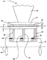
図1に示すように、蒸気タービン(これもまた参照符号10で示す)のような典型的な回転機械10は一般的に、ロータ35又は回転バケット65のような少なくとも1つの回転構成部品15と、該回転構成部品15を囲む固定蒸気ノズル(これもまた参照符号20で示す)のような固定構成部品20とを含む。回転構成部品15及び固定構成部品20は、共通の軸線92の周りで円周方向に配置される。蒸気タービン10の場合には、固定ノズル20を通って流れる蒸気は、高速で回転構成部品15に当たるように向けられて、該回転構成部品15を高速で回転させる。
As shown in FIG. 1, a typical
シール組立体120を、まず図1を参照して説明する。図示するように、シール組立体120は、回転構成部品15と固定構成部品20との間に配置される。更に、図1を参照すると、シール組立体120は、回転構成部品15又は固定構成部品20のどちらかに固定された少なくとも1つのシールストリップ30を含む。アブレイダブル部分55が、回転構成部品15及び固定構成部品20の他方上に配置される。
First, the
図1及び図2は、シール組立体120の実施形態を示し、これらの実施形態において、少なくとも1つシールストリップ30が、回転構成部品15に固定され、またアブレイダブル部分55が、固定構成部品20上に配置される。図2に示す特定の実施形態の場合には、回転構成部品は、ロータ35を含み、また固定構成部品は、ノズルカバー42を有するノズル20を含む。図2に示す特定の実施形態の場合には、一連のシールストリップ30が、適当な取付け手段45、例えば典型的にはかしめワイヤ45によってロータ35に固定される。アブレイダブル部分55が、ノズルカバー42の外側表面50上に配置され、かつシールストリップ30と半径方向に対向して位置決めされる。図3に示す特定の実施形態の場合には、回転構成部品は、先端60を有するバケット65を含み、また固定構成部品は、ケーシング40を含む。ここで用いられる場合、バケット先端60は、例えば図3に示すようにバケット65上のカバー62の先端である。図示するように、シールストリップ30は、バケット先端60に固定される。シールストリップ30は典型的には、望ましくは約0.127mm(0.005インチ)から約2.54mm(0.100インチ)までの範囲、より具体的には約0.254mm(0.010インチ)から約0.762mm(0.030インチ)の範囲の厚さを有する。シールストリップ30の厚さを望ましい範囲内に維持することは、シールストリップ30がアブレイダブル部分55と干渉してアブレイダブル粒子の局部的塑性変形を引き起こす場合に、シールストリップ30の完全性を保つ利点がある。従って、摩耗デブリがシールストリップ30とアブレイダブル部分55との間に入り込むことにより、アブレイダブル粒子がアブレイダブル皮膜の次の層から解放されて新しいアブレイダブル層を形成し、該デブリがアブレイダブル部分55上へ侵入するのを最小限にする。
1 and 2 show embodiments of a
図2から図4までを参照すると、アブレイダブル部分55は典型的には、該アブレイダブル部分55が配置されている表面50、75、90から距離「s」にわたって突出する。シールストリップ30と該シールストリップ30と半径方向に対向する表面50、75、90との間の冷間時の半径方向間隙「t」は、タービンバケット65又はタービンロータ35のアブレイダブル部分55内への最大予測半径方向侵入量のような要因に基づいて決定することができる。従って、冷間時の半径方向間隙「t」は、回転機械10の所定の偏向量と該回転機械10の過渡状態又は定常状態運転の下でのタービンバケット65又はタービンロータ35の半径方向の偏向量とよって決まる。シールストリップ30が、回転機械10の典型的な運転状況の間、例えば始動及び過渡状態の間に表面50、75、90に干渉するとき、アブレイダブル部分55は一般的に、シールストリップ30を起こり得る摩耗に対して保護する。すなわち、アブレイダブル部分55は、犠牲皮膜を含み、この犠牲皮膜は、シールストリップ30になんらの損傷も生じさせることなく該シールストリップ30によって窪まされながら、該シールストリップ30をその上に配置されたアブレイダブル部分55を有する表面50、75、90に対して擦過させる。従って、シールストリップ30と該シールストリップ30と半径方向に対向する表面50、75、90との間の冷間時の間隙「t」は、「狭い間隙」値に維持することが可能である。この「狭い間隙」値を維持することにより、該間隙を通って流れる流体にかかる抵抗が大きくなるため、シールストリップ30と表面50、75、90との間の流れ空間を通しての洩れを減少させる利点がある。この流れ空間を通しての洩れを減少させることで、回転機械10の全体効率及び性能が向上する。
Referring to FIGS. 2-4, the
バケット65又はロータ35のような回転構成部品15とケーシング40又はノズル20のような固定構成部品との間の整列不良は、シールストリップ30とアブレイダブル部分55との干渉を引き起こす。シールストリップ30がアブレイダブル部分55の表面上を摺動するとき、回転力又は転動力と侵入力との複合作用により、アブレイダブル皮膜中の粒子が押しのけられて、アブレイダブル部分55上に侵入跡が生じる。従って、アブレイダブル材料は、望ましくは、起こりうる全ての切込み状態の下での擦過の間に破断、層剥離、又は回転構成部品に対する損傷を引き起こすことなく安定した状態に保たれるべきである。より具体的には、表面50、75、90上に配置されたアブレイダブル皮膜は、該皮膜によるシールストリップ30への損傷を防止するために望ましくは充分な多孔性を備えるべきである。例えば、アブレイダブル皮膜は、望ましくは約15から約60体積百分率の範囲、より具体的には、約25から約50体積百分率の範囲の多孔性を備えるべきである。更に、表面50、75、90上に配置されたアブレイダブル皮膜は、約0.001インチから約0.015インチの間の、より具体的には約0.010インチから約0.060インチの間の、更により具体的には約0.015インチから約0.055インチの間の厚さを備えるべきである。
Misalignment between the
従って、アブレイダブル材料は、望ましくは、それに限定するのではないが、例えばシールストリップ材料、シール組立体の運転温度、回転機械の先端速度、及び侵入率を含む変化する擦過状態の下での異なる摩耗作用を吸収すべきである。従って、例示的なシールストリップ30は、オーステナイト系ステンレス鋼、フェライト系ステンレス鋼、ニッケル基超合金、コバルト基超合金、高分子材料、及びそれらの組み合わせのような材料を含む。図2に示す1つの実施形態では、シールストリップ30は、その耐摩耗性を更に高めるためにアブレイシブ皮膜80を含む。例示的なアブレイシブ皮膜80には、アルミナ、炭化クロム、及びステライトが含まれる。
Accordingly, the abradable material is desirably under varying fretting conditions including, but not limited to, seal strip material, operating temperature of the seal assembly, tip speed of the rotating machine, and penetration rates. Different wear effects should be absorbed. Accordingly, exemplary seal strips 30 include materials such as austenitic stainless steels, ferritic stainless steels, nickel-based superalloys, cobalt-based superalloys, polymeric materials, and combinations thereof. In one embodiment, shown in FIG. 2, the sealing
アブレイダブル部分55を形成するための例示的なアブレイダブル材料には、溶射被覆材料、Feltmetal(商標)(フロリダ州Deland所在のTechnectics社により販売されている)のような燒結金属繊維、及びハニカム構造を有する材料が含まれる。ハニカム構造を有する例示的な材料には、ハニカム構造で形成された金属又はセラミック材料が含まれる。例示的な溶射被覆材料は、例えばコバルト、ニッケル、クロム、アルミニウム、イットリウム(以後はCoNiCrAlYと呼ぶ)のような第1の構成部品と、例えば六方晶窒化ボロン、熱硬化性ポリマー、又はそれらの組み合わせのような第2の構成部品とを含む。有利なことに、六方晶窒化ボロンのような材料は、その構造体を多孔質にし、それによってアブレイダブル皮膜のアブレイダブル性を向上させる。当業者には分かるであろうが、他の固体潤滑剤を使用することもできる。一般的に、アブレイダブル皮膜の望ましい多孔性を得ることは、溶射皮膜法自体を制御するか又は熱硬化性ポリマーを添加することにより達成される。例示的な熱硬化性ポリマーには、ポリエステル及びポリアミドが含まれる。
Exemplary abradable materials for forming the
シール組立体120は更に、付加的なシール機構を組み入れて、シール機能を高めることができる。図4に示す実施形態の場合には、シール組立体120は更に、少なくとも1つのばねを有するばね付勢式シール支持セグメント100を含み、この少なくとも1つのばねは、該シール支持セグメント100が回転構成部品35に隣接して配置された状態に保持されるように配置される。アブレイダブル部分55は、シール支持セグメント100の上部表面90上に配置される。例示的なばね110には、板ばね及びコイルばねが含まれる。ばね110は一般的に、回転機械10内に組み付けられたとき、該ばねが支えるシール支持セグメント100の重量の約2倍乃至約5倍の範囲内の半径方向力を加える。運転中、ばね110は、シール支持セグメント100を固定構成部品40に向かって半径方向に「着座させる」のに充分な力を与え、該シール支持セグメント100をタービンロータ35に隣接して配置された状態に保つ必要があるだけである。
本明細書では本発明を特許規則に従って図示しかつ説明してきたが、本発明の技術思想及び技術的範囲から逸脱することなく、開示した実施形態に改良及び変更を加えることが可能であることは、当業者には明らかであろう。特許請求の範囲に示した参照符号は、本発明の技術的範囲を限定するためではなく、それらを容易に理解するためのものである。 Although the present invention has been shown and described herein in accordance with the Patents Regulations, it should be understood that improvements and changes can be made in the disclosed embodiments without departing from the spirit and scope of the invention. Will be apparent to those skilled in the art. Reference numerals in the claims are not for limiting the technical scope of the present invention, but for understanding them easily.
10 回転機械
20 固定構成部品
30 シールストリップ
35 ロータ
42 ノズルカバー
45 かしめワイヤ
50 ノズルカバーの外側表面
55 アブレイダブル部分
80 アブレイシブ皮膜
92 共通の軸線
120 シール組立体
DESCRIPTION OF
Claims (10)
前記回転構成部品及び固定構成部品の一方に固定された少なくとも1つのシールストリップ(30)と、
前記回転構成部品及び固定構成部品の他方上に配置され、かつ前記少なくとも1つのシールストリップと半径方向に対向して位置決めされたアブレイダブル部分(55)と、
を含むことを特徴とするシール組立体(120)。 A seal assembly (120) for positioning within a rotating machine (10) between a rotating component (15) and a stationary component (20) of the rotating machine, the seal assembly (120) comprising:
At least one sealing strip (30) secured to one of said rotating component and stationary component;
An abradable portion (55) disposed on the other of the rotating component and the stationary component and positioned radially opposite the at least one sealing strip;
A seal assembly (120), comprising:
回転構成部品(15)と、
前記回転構成部品を囲む固定構成部品(20)と、を含み、
前記回転構成部品及び固定構成部品が、共通の軸線の周りに配置され、
シール組立体(120)が、前記回転構成部品と前記固定構成部品との間に配置されており、
前記シール組立体(120)が、前記回転構成部品及び固定構成部品の一方に固定された少なくとも1つのシールストリップ(30)と、前記回転構成部品及び固定構成部品の他方上に配置されたアブレイダブル部分(55)とを含み、
前記アブレイダブル部分が、前記少なくとも1つのシールストリップと半径方向に対向して位置決めされている、
ことを特徴とする回転機械(10)。 A rotary machine (10) having a plurality of stages,
Rotating components (15);
A stationary component (20) surrounding the rotating component;
The rotating component and the stationary component are arranged around a common axis;
A seal assembly (120) is disposed between the rotating component and the stationary component;
The seal assembly (120) includes at least one seal strip (30) secured to one of the rotating and stationary components and an abrasion disposed on the other of the rotating and stationary components. A double part (55),
The abradable portion is positioned radially opposite the at least one seal strip;
A rotating machine (10), characterized in that:
Applications Claiming Priority (1)
| Application Number | Priority Date | Filing Date | Title |
|---|---|---|---|
| US10/248,259 US6969231B2 (en) | 2002-12-31 | 2002-12-31 | Rotary machine sealing assembly |
Publications (2)
| Publication Number | Publication Date |
|---|---|
| JP2004211896A true JP2004211896A (en) | 2004-07-29 |
| JP2004211896A5 JP2004211896A5 (en) | 2007-02-15 |
Family
ID=32592780
Family Applications (1)
| Application Number | Title | Priority Date | Filing Date |
|---|---|---|---|
| JP2003432088A Pending JP2004211896A (en) | 2002-12-31 | 2003-12-26 | Sealing assembly for rotary machine |
Country Status (4)
| Country | Link |
|---|---|
| US (1) | US6969231B2 (en) |
| JP (1) | JP2004211896A (en) |
| CN (1) | CN1515811A (en) |
| DE (1) | DE10361499A1 (en) |
Cited By (6)
| Publication number | Priority date | Publication date | Assignee | Title |
|---|---|---|---|---|
| JP2006233971A (en) * | 2005-02-24 | 2006-09-07 | General Electric Co <Ge> | Automated sealing strip assembling method and apparatus for rotary machine |
| JP2007064482A (en) * | 2005-08-29 | 2007-03-15 | Man Turbo Ag | Shaft seal structure for transmission expander or transmission compressor, and transmission expander or transmission compressor therewith |
| JP2007170302A (en) * | 2005-12-22 | 2007-07-05 | Toshiba Corp | Seal device |
| JP2007298040A (en) * | 2006-05-05 | 2007-11-15 | General Electric Co <Ge> | Rotating machine and bling assembly |
| JP2009236038A (en) * | 2008-03-27 | 2009-10-15 | Toshiba Corp | Steam turbine |
| US8240675B2 (en) | 2008-01-25 | 2012-08-14 | Mitsubishi Heavy Industries, Ltd. | Seal structure |
Families Citing this family (33)
| Publication number | Priority date | Publication date | Assignee | Title |
|---|---|---|---|---|
| DE10356953B4 (en) * | 2003-12-05 | 2016-01-21 | MTU Aero Engines AG | Inlet lining for gas turbines and method for producing the same |
| DE102004046111A1 (en) * | 2004-09-23 | 2006-04-06 | Elringklinger Ag | Process for coating flat gaskets |
| US20060249911A1 (en) * | 2005-05-04 | 2006-11-09 | General Electric Company | Abradable and/or abrasive coating and brush seal configuration |
| JP4886271B2 (en) * | 2005-10-31 | 2012-02-29 | 株式会社東芝 | Steam turbine and hydrophilic coating material thereof |
| US20070132193A1 (en) * | 2005-12-13 | 2007-06-14 | Wolfe Christopher E | Compliant abradable sealing system and method for rotary machines |
| DE102006009860A1 (en) * | 2006-03-03 | 2007-09-06 | Mtu Aero Engines Gmbh | Method for producing a sealing segment and sealing segment for use in compressor and turbine components |
| US7572099B2 (en) * | 2006-07-06 | 2009-08-11 | United Technologies Corporation | Seal for turbine engine |
| JP2008169705A (en) | 2007-01-09 | 2008-07-24 | Toshiba Corp | Steam turbine |
| US7871244B2 (en) * | 2007-02-15 | 2011-01-18 | Siemens Energy, Inc. | Ring seal for a turbine engine |
| US8205333B2 (en) * | 2008-03-06 | 2012-06-26 | General Electric Company | Method and system for fabricating a seal ring |
| US20100050649A1 (en) * | 2008-09-04 | 2010-03-04 | Allen David B | Combustor device and transition duct assembly |
| US8550468B1 (en) * | 2008-09-15 | 2013-10-08 | The United States Of America As Represented By The Administrator Of The National Aeronautics And Space Administration | Seal apparatus and methods to manufacture thereof |
| JP5411569B2 (en) * | 2009-05-01 | 2014-02-12 | 株式会社日立製作所 | Seal structure and control method |
| JP5210984B2 (en) * | 2009-06-29 | 2013-06-12 | 株式会社日立製作所 | Highly reliable metal sealant for turbines |
| DE102009034025A1 (en) * | 2009-07-21 | 2011-01-27 | Mtu Aero Engines Gmbh | Inlet lining for arrangement on a gas turbine component |
| DE102009053954A1 (en) * | 2009-11-19 | 2011-06-09 | Siemens Aktiengesellschaft | Labyrinth seal and method of making a labyrinth seal |
| US8591181B2 (en) * | 2010-10-18 | 2013-11-26 | General Electric Company | Turbomachine seal assembly |
| US8845283B2 (en) * | 2010-11-29 | 2014-09-30 | General Electric Company | Compressor blade with flexible tip elements and process therefor |
| US20120189434A1 (en) * | 2011-01-26 | 2012-07-26 | United Technologies Corporation | Coating with abradability proportional to interaction rate |
| CN102168239B (en) * | 2011-03-29 | 2012-12-05 | 北京矿冶研究总院 | Composite powder for abradable seal, coating and preparation method |
| US8454023B2 (en) * | 2011-05-10 | 2013-06-04 | General Electric Company | Retractable seal system |
| US8888446B2 (en) * | 2011-10-07 | 2014-11-18 | General Electric Company | Turbomachine rotor having patterned coating |
| GB2496887A (en) * | 2011-11-25 | 2013-05-29 | Rolls Royce Plc | Gas turbine engine abradable liner |
| US10301949B2 (en) * | 2013-01-29 | 2019-05-28 | United Technologies Corporation | Blade rub material |
| US9790863B2 (en) | 2013-04-05 | 2017-10-17 | Honeywell International Inc. | Fluid transfer seal assemblies, fluid transfer systems, and methods for transferring process fluid between stationary and rotating components using the same |
| US9506366B2 (en) | 2013-08-06 | 2016-11-29 | General Electric Company | Helical seal system for a turbomachine |
| CN104074558B (en) * | 2014-05-23 | 2016-01-20 | 浙江大学 | A kind of rotary brush labyrinth casing |
| US10247027B2 (en) | 2016-03-23 | 2019-04-02 | United Technologies Corporation | Outer airseal insulated rub strip |
| US10669878B2 (en) | 2016-03-23 | 2020-06-02 | Raytheon Technologies Corporation | Outer airseal abradable rub strip |
| US10267174B2 (en) | 2016-04-28 | 2019-04-23 | United Technologies Corporation | Outer airseal abradable rub strip |
| US10315249B2 (en) | 2016-07-29 | 2019-06-11 | United Technologies Corporation | Abradable material feedstock and methods and apparatus for manufacture |
| FR3058495B1 (en) * | 2016-11-09 | 2019-06-28 | Safran Aircraft Engines | DOUBLE SHAPE SEALING DEVICE, LABYRINTH SEAL AND MOBILE LATCH |
| US11913343B2 (en) * | 2019-10-03 | 2024-02-27 | Rtx Corporation | Replaceable rotor blade tip clearance measurement device for a gas turbine engine |
Citations (4)
| Publication number | Priority date | Publication date | Assignee | Title |
|---|---|---|---|---|
| US3537713A (en) * | 1968-02-21 | 1970-11-03 | Garrett Corp | Wear-resistant labyrinth seal |
| WO2001083951A1 (en) * | 2000-05-04 | 2001-11-08 | Siemens Aktiengesellschaft | System for sealing off a gap |
| JP2002228013A (en) * | 2001-02-01 | 2002-08-14 | Mitsubishi Heavy Ind Ltd | Acc type labyrinth seal |
| US20020192074A1 (en) * | 2001-06-18 | 2002-12-19 | Turnquist Norman Arnold | Spring-backed abradable seal for turbomachinery |
Family Cites Families (23)
| Publication number | Priority date | Publication date | Assignee | Title |
|---|---|---|---|---|
| US3879831A (en) * | 1971-11-15 | 1975-04-29 | United Aircraft Corp | Nickle base high temperature abradable material |
| US3966356A (en) | 1975-09-22 | 1976-06-29 | General Motors Corporation | Blade tip seal mount |
| US4080204A (en) | 1976-03-29 | 1978-03-21 | Brunswick Corporation | Fenicraly alloy and abradable seals made therefrom |
| US4433845A (en) | 1981-09-29 | 1984-02-28 | United Technologies Corporation | Insulated honeycomb seal |
| FR2570764B1 (en) | 1984-09-27 | 1986-11-28 | Snecma | DEVICE FOR AUTOMATICALLY CONTROLLING THE PLAY OF A TURBOMACHINE LABYRINTH SEAL |
| JPH02298604A (en) | 1989-05-11 | 1990-12-11 | Toshiba Corp | Blade tip leakage preventing device for axial flow fluid machine |
| US5536022A (en) * | 1990-08-24 | 1996-07-16 | United Technologies Corporation | Plasma sprayed abradable seals for gas turbine engines |
| US5196471A (en) | 1990-11-19 | 1993-03-23 | Sulzer Plasma Technik, Inc. | Thermal spray powders for abradable coatings, abradable coatings containing solid lubricants and methods of fabricating abradable coatings |
| US5603510A (en) * | 1991-06-13 | 1997-02-18 | Sanders; William P. | Variable clearance seal assembly |
| US5314304A (en) * | 1991-08-15 | 1994-05-24 | The United States Of America As Represented By The Secretary Of The Air Force | Abradeable labyrinth stator seal |
| US5188507A (en) | 1991-11-27 | 1993-02-23 | General Electric Company | Low-pressure turbine shroud |
| US6131910A (en) | 1992-11-19 | 2000-10-17 | General Electric Co. | Brush seals and combined labyrinth and brush seals for rotary machines |
| US5749584A (en) | 1992-11-19 | 1998-05-12 | General Electric Company | Combined brush seal and labyrinth seal segment for rotary machines |
| US5927942A (en) | 1993-10-27 | 1999-07-27 | United Technologies Corporation | Mounting and sealing arrangement for a turbine shroud segment |
| US5456576A (en) * | 1994-08-31 | 1995-10-10 | United Technologies Corporation | Dynamic control of tip clearance |
| US5599026A (en) | 1995-09-06 | 1997-02-04 | Innovative Technology, L.L.C. | Turbine seal with sealing strip and rubbing strip |
| US5735667A (en) * | 1996-05-06 | 1998-04-07 | Innovative Technology, L.L.C. | Method and apparatus for minimizing leakage in turbine seals |
| DE19640979A1 (en) | 1996-10-04 | 1998-04-16 | Asea Brown Boveri | Brush seal |
| US6027121A (en) | 1997-10-23 | 2000-02-22 | General Electric Co. | Combined brush/labyrinth seal for rotary machines |
| US6045134A (en) | 1998-02-04 | 2000-04-04 | General Electric Co. | Combined labyrinth and brush seals for rotary machines |
| US6220814B1 (en) | 1998-07-16 | 2001-04-24 | Siemens Westinghouse Power Corporation | Turbine interstage sealing arrangement |
| US5971400A (en) | 1998-08-10 | 1999-10-26 | General Electric Company | Seal assembly and rotary machine containing such seal assembly |
| US6340286B1 (en) | 1999-12-27 | 2002-01-22 | General Electric Company | Rotary machine having a seal assembly |
-
2002
- 2002-12-31 US US10/248,259 patent/US6969231B2/en not_active Expired - Lifetime
-
2003
- 2003-12-23 DE DE10361499A patent/DE10361499A1/en not_active Ceased
- 2003-12-26 CN CNA2003101247408A patent/CN1515811A/en active Pending
- 2003-12-26 JP JP2003432088A patent/JP2004211896A/en active Pending
Patent Citations (4)
| Publication number | Priority date | Publication date | Assignee | Title |
|---|---|---|---|---|
| US3537713A (en) * | 1968-02-21 | 1970-11-03 | Garrett Corp | Wear-resistant labyrinth seal |
| WO2001083951A1 (en) * | 2000-05-04 | 2001-11-08 | Siemens Aktiengesellschaft | System for sealing off a gap |
| JP2002228013A (en) * | 2001-02-01 | 2002-08-14 | Mitsubishi Heavy Ind Ltd | Acc type labyrinth seal |
| US20020192074A1 (en) * | 2001-06-18 | 2002-12-19 | Turnquist Norman Arnold | Spring-backed abradable seal for turbomachinery |
Cited By (9)
| Publication number | Priority date | Publication date | Assignee | Title |
|---|---|---|---|---|
| JP2006233971A (en) * | 2005-02-24 | 2006-09-07 | General Electric Co <Ge> | Automated sealing strip assembling method and apparatus for rotary machine |
| JP4674764B2 (en) * | 2005-02-24 | 2011-04-20 | ゼネラル・エレクトリック・カンパニイ | Automated seal strip assembly method and apparatus for rotating machine |
| JP2007064482A (en) * | 2005-08-29 | 2007-03-15 | Man Turbo Ag | Shaft seal structure for transmission expander or transmission compressor, and transmission expander or transmission compressor therewith |
| JP2007170302A (en) * | 2005-12-22 | 2007-07-05 | Toshiba Corp | Seal device |
| JP4718991B2 (en) * | 2005-12-22 | 2011-07-06 | 株式会社東芝 | Sealing device |
| JP2007298040A (en) * | 2006-05-05 | 2007-11-15 | General Electric Co <Ge> | Rotating machine and bling assembly |
| KR101410563B1 (en) * | 2006-05-05 | 2014-06-23 | 제너럴 일렉트릭 캄파니 | Rotary machines and methods of assembling |
| US8240675B2 (en) | 2008-01-25 | 2012-08-14 | Mitsubishi Heavy Industries, Ltd. | Seal structure |
| JP2009236038A (en) * | 2008-03-27 | 2009-10-15 | Toshiba Corp | Steam turbine |
Also Published As
| Publication number | Publication date |
|---|---|
| US6969231B2 (en) | 2005-11-29 |
| CN1515811A (en) | 2004-07-28 |
| US20040126225A1 (en) | 2004-07-01 |
| DE10361499A1 (en) | 2004-07-15 |
Similar Documents
| Publication | Publication Date | Title |
|---|---|---|
| JP2004211896A (en) | Sealing assembly for rotary machine | |
| KR100733175B1 (en) | Spring-backed abradable seal for turbomachinery | |
| EP1801472B1 (en) | Sealing device | |
| US6572115B1 (en) | Actuating seal for a rotary machine and method of retrofitting | |
| US7857582B2 (en) | Abradable labyrinth tooth seal | |
| US7600968B2 (en) | Pattern for the surface of a turbine shroud | |
| US6533285B2 (en) | Abradable coating and method of production | |
| US7614847B2 (en) | Pattern for the surface of a turbine shroud | |
| US6340286B1 (en) | Rotary machine having a seal assembly | |
| US9145788B2 (en) | Retrofittable interstage angled seal | |
| CN100590297C (en) | Expanding sealing strips for steam turbines | |
| CN101131101A (en) | Angel wing abradable seal and sealing method | |
| EP1510655B1 (en) | Brush seal support | |
| EP2141328A1 (en) | Sealing system between a shroud segment and a rotor blade tip and manufacturing method for such a segment | |
| EP2904216B1 (en) | Aluminum based abradable material with reduced metal transfer to blades | |
| JP2005291205A (en) | Sealing device and method for turbomachinery | |
| EP3249170B1 (en) | Seal assembly with seal rings for gas turbine engines | |
| EP1712743A2 (en) | Turbine with an abradable seal between the rotor and a stationary component | |
| US6692228B2 (en) | Rotor insert assembly and method of retrofitting | |
| US9829007B2 (en) | Turbine sealing system | |
| US6761530B1 (en) | Method and apparatus to facilitate reducing turbine packing leakage losses | |
| US20110182721A1 (en) | Sealing arrangement for a gas turbine engine | |
| JP6197985B2 (en) | Seal structure and turbine device provided with the same | |
| CN115011845A (en) | Anti-fretting coating composition and coated part |
Legal Events
| Date | Code | Title | Description |
|---|---|---|---|
| A521 | Request for written amendment filed |
Free format text: JAPANESE INTERMEDIATE CODE: A523 Effective date: 20061226 |
|
| A621 | Written request for application examination |
Free format text: JAPANESE INTERMEDIATE CODE: A621 Effective date: 20061226 |
|
| A977 | Report on retrieval |
Free format text: JAPANESE INTERMEDIATE CODE: A971007 Effective date: 20090909 |
|
| A131 | Notification of reasons for refusal |
Free format text: JAPANESE INTERMEDIATE CODE: A131 Effective date: 20090915 |
|
| A601 | Written request for extension of time |
Free format text: JAPANESE INTERMEDIATE CODE: A601 Effective date: 20091215 |
|
| RD02 | Notification of acceptance of power of attorney |
Free format text: JAPANESE INTERMEDIATE CODE: A7422 Effective date: 20091215 |
|
| RD04 | Notification of resignation of power of attorney |
Free format text: JAPANESE INTERMEDIATE CODE: A7424 Effective date: 20091215 |
|
| A521 | Request for written amendment filed |
Free format text: JAPANESE INTERMEDIATE CODE: A523 Effective date: 20091224 |
|
| A602 | Written permission of extension of time |
Free format text: JAPANESE INTERMEDIATE CODE: A602 Effective date: 20100104 |
|
| A601 | Written request for extension of time |
Free format text: JAPANESE INTERMEDIATE CODE: A601 Effective date: 20100115 |
|
| A602 | Written permission of extension of time |
Free format text: JAPANESE INTERMEDIATE CODE: A602 Effective date: 20100120 |
|
| A601 | Written request for extension of time |
Free format text: JAPANESE INTERMEDIATE CODE: A601 Effective date: 20100215 |
|
| A602 | Written permission of extension of time |
Free format text: JAPANESE INTERMEDIATE CODE: A602 Effective date: 20100218 |
|
| A521 | Request for written amendment filed |
Free format text: JAPANESE INTERMEDIATE CODE: A523 Effective date: 20100315 |
|
| A02 | Decision of refusal |
Free format text: JAPANESE INTERMEDIATE CODE: A02 Effective date: 20100713 |
|
| A521 | Request for written amendment filed |
Free format text: JAPANESE INTERMEDIATE CODE: A523 Effective date: 20101112 |
|
| A911 | Transfer to examiner for re-examination before appeal (zenchi) |
Free format text: JAPANESE INTERMEDIATE CODE: A911 Effective date: 20110127 |
|
| A912 | Re-examination (zenchi) completed and case transferred to appeal board |
Free format text: JAPANESE INTERMEDIATE CODE: A912 Effective date: 20110318 |
|
| A601 | Written request for extension of time |
Free format text: JAPANESE INTERMEDIATE CODE: A601 Effective date: 20110725 |
|
| A602 | Written permission of extension of time |
Free format text: JAPANESE INTERMEDIATE CODE: A602 Effective date: 20110728 |