EP3249170B1 - Seal assembly with seal rings for gas turbine engines - Google Patents
Seal assembly with seal rings for gas turbine engines Download PDFInfo
- Publication number
- EP3249170B1 EP3249170B1 EP17172486.7A EP17172486A EP3249170B1 EP 3249170 B1 EP3249170 B1 EP 3249170B1 EP 17172486 A EP17172486 A EP 17172486A EP 3249170 B1 EP3249170 B1 EP 3249170B1
- Authority
- EP
- European Patent Office
- Prior art keywords
- seal
- tab
- ring
- flow channel
- shelf
- Prior art date
- Legal status (The legal status is an assumption and is not a legal conclusion. Google has not performed a legal analysis and makes no representation as to the accuracy of the status listed.)
- Active
Links
- 239000007789 gas Substances 0.000 description 26
- 230000004323 axial length Effects 0.000 description 6
- 230000003068 static effect Effects 0.000 description 5
- 238000007789 sealing Methods 0.000 description 4
- 239000000463 material Substances 0.000 description 3
- 230000000712 assembly Effects 0.000 description 2
- 238000000429 assembly Methods 0.000 description 2
- 238000001816 cooling Methods 0.000 description 2
- 230000003247 decreasing effect Effects 0.000 description 2
- 239000012530 fluid Substances 0.000 description 2
- 239000000446 fuel Substances 0.000 description 2
- 238000004519 manufacturing process Methods 0.000 description 2
- 239000002184 metal Substances 0.000 description 2
- 229910052751 metal Inorganic materials 0.000 description 2
- 238000012986 modification Methods 0.000 description 2
- 230000004048 modification Effects 0.000 description 2
- 229910000531 Co alloy Inorganic materials 0.000 description 1
- 230000000903 blocking effect Effects 0.000 description 1
- 230000008859 change Effects 0.000 description 1
- 239000011248 coating agent Substances 0.000 description 1
- 238000000576 coating method Methods 0.000 description 1
- 238000002485 combustion reaction Methods 0.000 description 1
- 230000001010 compromised effect Effects 0.000 description 1
- 230000007423 decrease Effects 0.000 description 1
- 230000001419 dependent effect Effects 0.000 description 1
- 230000005855 radiation Effects 0.000 description 1
- 230000001052 transient effect Effects 0.000 description 1
- 238000003466 welding Methods 0.000 description 1
Images


Classifications
-
- F—MECHANICAL ENGINEERING; LIGHTING; HEATING; WEAPONS; BLASTING
- F01—MACHINES OR ENGINES IN GENERAL; ENGINE PLANTS IN GENERAL; STEAM ENGINES
- F01D—NON-POSITIVE DISPLACEMENT MACHINES OR ENGINES, e.g. STEAM TURBINES
- F01D11/00—Preventing or minimising internal leakage of working-fluid, e.g. between stages
- F01D11/005—Sealing means between non relatively rotating elements
-
- F—MECHANICAL ENGINEERING; LIGHTING; HEATING; WEAPONS; BLASTING
- F01—MACHINES OR ENGINES IN GENERAL; ENGINE PLANTS IN GENERAL; STEAM ENGINES
- F01D—NON-POSITIVE DISPLACEMENT MACHINES OR ENGINES, e.g. STEAM TURBINES
- F01D11/00—Preventing or minimising internal leakage of working-fluid, e.g. between stages
- F01D11/003—Preventing or minimising internal leakage of working-fluid, e.g. between stages by packing rings; Mechanical seals
-
- F—MECHANICAL ENGINEERING; LIGHTING; HEATING; WEAPONS; BLASTING
- F01—MACHINES OR ENGINES IN GENERAL; ENGINE PLANTS IN GENERAL; STEAM ENGINES
- F01D—NON-POSITIVE DISPLACEMENT MACHINES OR ENGINES, e.g. STEAM TURBINES
- F01D11/00—Preventing or minimising internal leakage of working-fluid, e.g. between stages
- F01D11/08—Preventing or minimising internal leakage of working-fluid, e.g. between stages for sealing space between rotor blade tips and stator
-
- F—MECHANICAL ENGINEERING; LIGHTING; HEATING; WEAPONS; BLASTING
- F16—ENGINEERING ELEMENTS AND UNITS; GENERAL MEASURES FOR PRODUCING AND MAINTAINING EFFECTIVE FUNCTIONING OF MACHINES OR INSTALLATIONS; THERMAL INSULATION IN GENERAL
- F16J—PISTONS; CYLINDERS; SEALINGS
- F16J15/00—Sealings
- F16J15/02—Sealings between relatively-stationary surfaces
- F16J15/021—Sealings between relatively-stationary surfaces with elastic packing
- F16J15/022—Sealings between relatively-stationary surfaces with elastic packing characterised by structure or material
- F16J15/024—Sealings between relatively-stationary surfaces with elastic packing characterised by structure or material the packing being locally weakened in order to increase elasticity
-
- F—MECHANICAL ENGINEERING; LIGHTING; HEATING; WEAPONS; BLASTING
- F16—ENGINEERING ELEMENTS AND UNITS; GENERAL MEASURES FOR PRODUCING AND MAINTAINING EFFECTIVE FUNCTIONING OF MACHINES OR INSTALLATIONS; THERMAL INSULATION IN GENERAL
- F16J—PISTONS; CYLINDERS; SEALINGS
- F16J15/00—Sealings
- F16J15/02—Sealings between relatively-stationary surfaces
- F16J15/06—Sealings between relatively-stationary surfaces with solid packing compressed between sealing surfaces
- F16J15/08—Sealings between relatively-stationary surfaces with solid packing compressed between sealing surfaces with exclusively metal packing
- F16J15/0887—Sealings between relatively-stationary surfaces with solid packing compressed between sealing surfaces with exclusively metal packing the sealing effect being obtained by elastic deformation of the packing
-
- F—MECHANICAL ENGINEERING; LIGHTING; HEATING; WEAPONS; BLASTING
- F16—ENGINEERING ELEMENTS AND UNITS; GENERAL MEASURES FOR PRODUCING AND MAINTAINING EFFECTIVE FUNCTIONING OF MACHINES OR INSTALLATIONS; THERMAL INSULATION IN GENERAL
- F16J—PISTONS; CYLINDERS; SEALINGS
- F16J15/00—Sealings
- F16J15/44—Free-space packings
-
- F—MECHANICAL ENGINEERING; LIGHTING; HEATING; WEAPONS; BLASTING
- F05—INDEXING SCHEMES RELATING TO ENGINES OR PUMPS IN VARIOUS SUBCLASSES OF CLASSES F01-F04
- F05D—INDEXING SCHEME FOR ASPECTS RELATING TO NON-POSITIVE-DISPLACEMENT MACHINES OR ENGINES, GAS-TURBINES OR JET-PROPULSION PLANTS
- F05D2220/00—Application
- F05D2220/30—Application in turbines
- F05D2220/32—Application in turbines in gas turbines
-
- F—MECHANICAL ENGINEERING; LIGHTING; HEATING; WEAPONS; BLASTING
- F05—INDEXING SCHEMES RELATING TO ENGINES OR PUMPS IN VARIOUS SUBCLASSES OF CLASSES F01-F04
- F05D—INDEXING SCHEME FOR ASPECTS RELATING TO NON-POSITIVE-DISPLACEMENT MACHINES OR ENGINES, GAS-TURBINES OR JET-PROPULSION PLANTS
- F05D2240/00—Components
- F05D2240/10—Stators
- F05D2240/15—Heat shield
-
- F—MECHANICAL ENGINEERING; LIGHTING; HEATING; WEAPONS; BLASTING
- F05—INDEXING SCHEMES RELATING TO ENGINES OR PUMPS IN VARIOUS SUBCLASSES OF CLASSES F01-F04
- F05D—INDEXING SCHEME FOR ASPECTS RELATING TO NON-POSITIVE-DISPLACEMENT MACHINES OR ENGINES, GAS-TURBINES OR JET-PROPULSION PLANTS
- F05D2240/00—Components
- F05D2240/55—Seals
-
- F—MECHANICAL ENGINEERING; LIGHTING; HEATING; WEAPONS; BLASTING
- F05—INDEXING SCHEMES RELATING TO ENGINES OR PUMPS IN VARIOUS SUBCLASSES OF CLASSES F01-F04
- F05D—INDEXING SCHEME FOR ASPECTS RELATING TO NON-POSITIVE-DISPLACEMENT MACHINES OR ENGINES, GAS-TURBINES OR JET-PROPULSION PLANTS
- F05D2250/00—Geometry
- F05D2250/70—Shape
- F05D2250/75—Shape given by its similarity to a letter, e.g. T-shaped
Definitions
- the present invention relates generally to seals, and more particularly to annular seals suitable for use in gas turbine engines.
- Annular seals are used in many applications, such as in pistons of combustion engines, in piping fittings, and in gas turbine engines. Annular seals are often used in gas turbine engines between components, such as vanes and blade outer air seals, to keep operating gasses and cooling gasses separate.
- W-seals are a type of seal capable of withstanding high pressures and are designed to expand and contract axially and circumferentially, allowing w-seals to seal cavities between components of gas turbine engines subjected to a variety of conditions.
- w-seals have been known to degrade from exposure to high temperatures as well as wear and stress from significant relative motion.
- Heat shields and wear shield have been used to reduce high temperature exposure and wear to w-seals.
- some heat shield designs are still prone to failure.
- US 2005/260066 A1 discloses a seal assembly as set forth in the preamble of claim 1.
- US 2011/150635 A1 discloses a seal and seal arrangement for confining leakage flows between adjacent components of turbo-machines and gas turbines.
- Heat shields and wear shields reduce high temperature exposure to and wear on primary seals (e.g., w-seals); however, prior art heat shield and wear shield designs that rely on secondary seals being resilient are prone to failure.
- Other prior art heat shield designs include heat shields that contact the w-seal near where the w-seal seals against a surface, causing potential wear on the w-seal and creating a potential for the seal to be compromised.
- Yet other prior art heat shields seal against one cavity wall and one axial surface of the w-seal, creating an additional leak-path and causing potential run-off and wear of the inboard convolution on the opposite end of the w-seal.
- the seal assembly invention prolongs the life of w-seals by adding a self-centering split ring seal that protects the w-seal from high temperatures and harsh wear surfaces and from escaping either inboard or outboard.
- FIG. 1 is a quarter-sectional view of gas turbine engine 20 that includes fan section 22, compressor section 24, combustor section 26, and turbine section 28.
- Alternative engines might include an augmenter section (not shown) among other systems or features.
- Fan section 22 drives air along bypass flow path B while compressor section 24 draws air in along core flow path C where air is compressed and communicated to combustor section 26.
- combustor section 26 air is mixed with fuel and ignited to generate a high pressure exhaust gas stream that expands through turbine section 28 where energy is extracted and utilized to drive fan section 22 and compressor section 24.
- turbofan gas turbine engine depicts a turbofan gas turbine engine
- the concepts described herein are not limited to use with turbofans as the teachings may be applied to other types of turbine engines; for example a turbine engine including a three-spool architecture in which three spools concentrically rotate about a common axis and where a low spool enables a low pressure turbine to drive a fan via a gearbox, an intermediate spool that enables an intermediate pressure turbine to drive a first compressor of the compressor section, and a high spool that enables a high pressure turbine to drive a high pressure compressor of the compressor section.
- the example engine 20 generally includes low speed spool 30 and high speed spool 32 mounted for rotation about an engine central longitudinal axis A relative to an engine static structure 36 via several bearing systems 38. It should be understood that various bearing systems 38 at various locations may alternatively or additionally be provided.
- Low speed spool 30 generally includes inner shaft 40 that connects fan 42 and low pressure (or first) compressor section 44 to low pressure (or first) turbine section 46.
- Inner shaft 40 drives fan 42 through a speed change device, such as geared architecture 48, to drive fan 42 at a lower speed than low speed spool 30.
- High-speed spool 32 includes outer shaft 50 that interconnects high pressure (or second) compressor section 52 and high pressure (or second) turbine section 54.
- Inner shaft 40 and outer shaft 50 are concentric and rotate via bearing systems 38 about engine central longitudinal axis A.
- Combustor 56 is arranged between high pressure compressor (HPC) 52 and high pressure turbine 54.
- high pressure turbine 54 includes at least two stages to provide a double stage high pressure turbine 54.
- high pressure turbine (HPT) 54 includes only a single stage.
- a "high pressure" compressor or turbine experiences a higher pressure than a corresponding "low pressure” compressor or turbine.
- the example low pressure turbine (LPT) 46 has a pressure ratio that is greater than about 5.
- the pressure ratio of the example low pressure turbine 46 is measured prior to an inlet of low pressure turbine 46 as related to the pressure measured at the outlet of low pressure turbine 46 prior to an exhaust nozzle.
- Mid-turbine frame 58 of engine static structure 36 is arranged generally between high pressure turbine 54 and low pressure turbine 46.
- Mid-turbine frame 58 further supports bearing systems 38 in turbine section 28 as well as setting airflow entering low pressure turbine 46.
- the core airflow C is compressed by low pressure compressor 44 then by high pressure compressor 52 mixed with fuel and ignited in combustor 56 to produce high speed exhaust gases that are then expanded through high pressure turbine 54 and low pressure turbine 46.
- Mid-turbine frame 58 includes airfoils/vanes 60, which are in the core airflow path and function as an inlet guide vane for low pressure turbine 46. Utilizing vanes 60 of mid-turbine frame 58 as inlet guide vanes for low pressure turbine 46 decreases the length of low pressure turbine 46 without increasing the axial length of mid-turbine frame 58. Reducing or eliminating the number of vanes in low pressure turbine 46 shortens the axial length of turbine section 28. Thus, the compactness of gas turbine engine 20 is increased and a higher power density may be achieved.
- FIG. 2 is a cross-sectional view of seal assembly 62, which can be located in high pressure turbine 54 of FIG. 1 .
- Seal assembly 62 includes blade outer air seal (BOAS) support 64, BOAS 66, blade 68, vane 70, vane support 71, w-seal 72, seal ring 74, first shelf 76, second shelf 78, cavity 82, and restricted flow channel 84.
- Seal ring 74 includes inner ring 86, outer ring 88, tab 90, and notch 92.
- core flow path C also shown in FIG. 2 are core flow path C, secondary flow S, and a representative engine central longitudinal axis A.
- BOAS support 64 is a rigid static component of gas turbine engine 20 that supports BOAS 66.
- BOAS 66 does not rotate, but is not entirely static, as BOAS 66 can shift radially and axially.
- a "static" component in the present context can be installed in an engine of a movable vehicle.
- BOAS 66 forms a seal for blade 68. Because blade 68 rotates within BOAS 66, a gap must be maintained between BOAS 66 and blade 68 to enable rotation of blade 68. This gap is known in the art as blade tip clearance.
- Vane 70 is also a non-rotating component, but is supported by vane support 71. Vane 70 is located downstream of BOAS support 64 and BOAS 66, relative to core flow path C.
- BOAS 66 includes first shelf 76 which extends axially aft from BOAS 66 towards vane 70, but stopping short of contacting vane 70.
- Vane 70 includes second shelf 78, which extends axially fore from vane 70 towards BOAS 66, but in the illustrated position terminates prior to contacting first shelf 76.
- First shelf 76 and second shelf 78 form restricted flow channel 84, which is fluidly connected to core flow path C and continues radially outward, connecting to cavity 82.
- BOAS 66, vane 70, first shelf 76, second shelf 78, and vane support 71 form cavity 82, which can receive secondary flow S, which is a cooling and pressurization flow, from a source such as HPC 52 (of FIG. 1 ), on the radially outward portion of cavity 82.
- W-seal 72 is a resilient annular w-type seal having two axially outer arms for contacting surfaces to form a seal. W-seal 72 also has multiple convolutions that provide resiliency and allow w-seal to conform to openings of varying sizes. In other embodiments, w-seal 72 can be a different type of annular seal such as a finger seal or dog-bone seal. W-seal 72 spans cavity 82 contacting radially extending surfaces of BOAS 66 and vane 70. The radially inner convolutions of w-seal 72 contact a surface of seal ring 74 (e.g., a radially outer surface of seal ring 74).
- seal ring 74 e.g., a radially outer surface of seal ring 74
- Seal ring 74 is a split ring annular seal made of a thin (e.g., 0.005 to 0.020 inches [0.125 to 0.5 mm]) sheet metal having a high temperature resistance, and a low coefficient of friction, such as a cobalt alloy. Seal ring 74 can be made of other materials in other embodiments. Seal ring 74 includes inner ring 86 and outer ring 88, which are both circumferentially split seal rings, wherein inner ring 86 is nested within outer ring 88.
- inner ring 86 and outer ring 88 are circumferentially spaced apart, or clocked, and are (largely or generally) restrained from circumferential movement by friction, but can be restrained in other ways, as discussed below.
- Inner ring 86 has a linear cross-sectional profile, apart from tab 90, and outer ring 88 has a linear cross-sectional profile.
- inner ring 86 and outer ring 88 can have other cross-sectional profiles in further embodiments.
- Tab 90 is a radially extending or projecting portion of inner ring 86, which extends radially inward and away from w-seal 72 in the illustrated embodiment.
- Tab 90 can be formed of inner ring 86 by a punch or similar manufacturing process, which creates both tab 90 and notch 92. In other embodiments, tab 90 can be an additional piece that is attached to inner ring 86. Seal ring 74 can include multiples of tab 90, as discussed further below.
- Seal ring 74 is positioned to rest on radially outer surfaces of first shelf 76 and second shelf 78. Tab 90 is inserted into restricted flow channel 84, which limits axial movement of seal ring 74 and helps center seal ring 74 relative to cavity 82. Seal ring 74 can be of an axial length so that seal ring 74 does not contact radially facing surfaces of BOAS 66 and vane 70.
- W-seal 72 forms a seal in cavity 82 that limits fluid flow between restricted flow channel 84 and cavity 82. Further, seal ring 74 creates a seal in restricted flow channel 84 at first shelf 76 and second shelf 78, further preventing restricted flow channel 84 from fluidly connecting to cavity 82.
- a radially inward force is created by secondary flow S that forces BOAS 66 and vane 70 radially toward core airflow C (e.g. inward) until BOAS 66 is seated on BOAS support 64 and vane 70 is seated on vane support 71.
- the pressure differential also forces w-seal 72 to move radially until w-seal 72 contacts seal ring 74, applying radial pressure on seal ring 74.
- w-seal 72 applies pressure on seal ring 74, causing seal ring 74 to seal restricted flow channel 84.
- inner ring 86 blocks the passage of gas from core flow path C.
- outer ring 88 prevents the passage of gas through notch 92 of inner ring 86, and circumferential splits of inner ring 86 and outer ring 88, forming a complete seal of restricted flow channel 84.
- seal ring 74 thermally protects w-seal 72 from core flow path C by blocking the passage of air from core flow path C and by preventing radiation heat transfer. Seal ring 74 also protects w-seal 72 from debris from core flow path C.
- w-seal 72 can be made of a material having a higher strength than a w-seal that is exposed to core flow path C, increasing the longevity of w-seal 72.
- Seal ring 74 also serves as a secondary seal in the case of a failure of w-seal 72.
- Tab 90 extends radially inward into restricted flow channel 84, but typically does not extend past restricted flow channel 84.
- Tab 90 can have an axial thickness that is smaller than an axial length of restricted flow channel 84 during non-operation and most operational conditions. This allows tab 90 to move axially within restricted flow channel 84. Accordingly, seal ring 74 can also move axially. However, the axial movement of tab 90 and therefore seal ring 74 is restricted by contact of tab 90 with first shelf 76 and/or second shelf 78. This keeps seal ring 74 roughly centered within cavity 82 and roughly centered about restricted flow channel 84, which has several benefits.
- first shelf 76 and second shelf 78 can have axial lengths and tab 90 can have an axial thickness so that tab 90 can move within restricted flow channel 84 such that seal ring 74 can move axially along first shelf 76 and second shelf 78, but so that seal ring 74 cannot contact radially extending surfaces of BOAS 66 and vane 70, which reduces biding and lifting of seal ring 74.
- seal ring 74 Because seal ring 74 has restrained axial movement, seal ring 74 maintains a seal of restricted flow path 84. Additionally, restricting axial movement of seal ring 74 reduces wear on w-seal 72 by providing a consistent surface for contact with the radially inner convolutions of w-seal 72 (which are not sealing surfaces of w-seal 72 in the illustrated embodiment). In other embodiments, a wear coating can be added to the radially outer surface of seal ring 74 to further enhance wear resistance of the W seal.
- restricted flow channel 84 and w-seal 72 can be sized to help prevent liberation of seal ring 74.
- w-seal 72 can move radially allowing seal ring 74 to move radially and axially. This has been problematic in some prior art seal assemblies, because secondary seals can sometimes liberate without pressure loads provided by secondary flow S.
- the present invention solves this problem in several ways. First, in one embodiment, because vane support 71, first shelf 76, and second shelf 78 restrict radial movement of w-seal 72, w-seal 72 cannot move far enough radially to allow tab 90 to move out of restricted flow channel 84, preventing liberation of seal ring 74 into core flow path C.
- tab 90 prevents liberation of seal ring 74 by preventing seal ring 74 from passing through restricted flow channel 84 when seal ring 74 is turned 90° from its position shown in FIG. 2 .
- Tab 90 prevents liberation at the 90° turned position of seal ring 74 by tab 90 being axially longer (when turned 90° from the illustrated position) than restricted flow channel 84 at all operating conditions.
- seal ring 74 is less likely to deteriorate because seal ring 74 need not be resilient and therefore can be made of a metal having a high temperature resistance, increasing component life of seal ring 74 and further decreasing the possibility of seal ring 74 entering core flow path C.
- Some secondary seals e.g. L-shaped heat shields
- Seal ring 74 does not interfere with sealing contact between w-seal 72 and the radially extending surfaces of BOAS 66 and vane 70, reducing leakage past w-seal 72 and seal ring 74.
- w-seals are designed to contact shelves or other stepped or uneven surfaces. This design can cause significant wear on radially inner convolutions of w-seals.
- Seal ring 74 reduces wear on w-seal 72 by providing a relatively flat contact surface to engage with w-seal 72. Additionally, because seal ring 74 has a low coefficient of friction, seal ring 74 encounters less damage when sliding on first shelf 76 and second shelf 78. Similarly, because seal ring 74 has a low coefficient of friction, damage incurred by w-seal 72 due to sliding on seal ring 74 is reduced by the low coefficient of friction of seal ring 74.
- Seal assembly 62 can be used in other areas of the gas turbine engine, such as turbine section 28. Additionally, seal ring 74 can be used to form seals between components of gas turbine engine 20 other than blades and vanes. Further, seal ring 74 can be used in applications other than for gas turbine engines, such as pumps having annular housings.
- FIG. 3A is a cross-sectional view of seal ring 74 and FIG. 3B is a plan view of a portion of seal ring 74 from perspective 3B-3B of FIG. 3A .
- Seal ring 74 includes inner ring 86, outer ring 88, tab 90, notch 92, and spot weld 94 (shown in FIG. 3A ).
- Spot weld 94 is located where axially extending surfaces of inner ring 86 and outer ring 88 meet at axial ends of inner ring 86 and outer ring 88. Spot weld 94 holds outer ring 88 and inner ring 86 together, ensuring that outer ring 88 seals notch 92, preventing gas from core flow path C (of FIGS. 1 and 2 ) from bypassing seal ring 74. Weld 94 also ensures that circumferential gaps in inner ring 86 and outer ring 88 stay correctly clocked (circumferentially spaced) from each other, as discussed below.
- Tab 90 can be formed from inner ring 86 so that tab 90 is slightly axially off-center. In other embodiments (especially in embodiments where tab 90 is not formed from inner ring 86), tab 90 can have any axial location along inner ring 86.
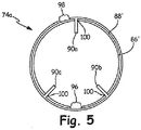
- FIG. 4 is a cross-sectional view of seal ring 74a and FIG. 5 is an elevation view of seal ring 74a, which includes inner ring 86', outer ring 88', tab 90' (illustrated as tabs 90a-90c in FIG. 5 ), notch 92', inner gap 96, outer gap 98, and second notch 100.
- Seal ring 74a is generally similar to seal ring 74 described above with respect to FIGS. 2 , 3A, and 3B , except that notch 92' of seal ring 74a is formed of outer ring 88' and extends through second notch 100 of inner ring 86'. Second notch 100 can be axially shorter than notch 92' (as well as notch 92).
- Tab 90' provides the functions and benefits described in FIGS. 2 and 3 .
- tab 90' and second notch 100 of seal ring 74a help prevent inner ring 86' from rotating relative to outer ring 88', maintaining the clocking or spacing of inner ring 86' and outer ring 88', which is important for preventing gasses from core flow path C from passing through circumferential splits in inner ring 86' and outer ring 88'.
- tab 90' and second notch 100 help prevent relative movement of inner ring 86' and outer ring 88', welding of inner ring 86' to outer ring 88' is not required, saving cost.
- Inner gap 96 is a circumferential gap in inner ring 86 that allows inner ring to expand and contract during operation of gas turbine engine 20.
- outer gap 98 is a circumferential gap in outer ring 88' that allows outer ring 98 to expand and contract.
- inner gap 96 and outer gap 98 can be spaced about 180 degrees, for example about 175 degrees. This spacing minimizes gas from core air flow C passing through inner gap 96 and outer gap 98, thus maintaining a seal of restricted flow channel 84.
- Tabs 90a-90c are connected to outer ring 86', consistent with the connection of tab 90' to outer ring 86' discussed above.
- FIG. 5 shows how three of tabs 90' (tabs 90a-90c) can be circumferentially arranged about outer ring 86'. In other embodiments, there can be fewer or more tabs.
- Tabs 90a-90c can be equally circumferentially spaced from each other. In the illustrated embodiment, tab 90a is approximately 175 degrees from inner gap 96. Tabs 90b and 90c are each spaced approximately 35 degrees from inner gap 96. This spacing minimizes bypass gas through notch 92', second notch 100 and outer split 98. Tabs 90a-90c can be spaced differently (e.g., unequally) in other embodiments.
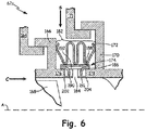
- FIG. 6 is a cross-sectional view of seal assembly 62a, which includes BOAS support 164, BOAS 166, blade 168, vane 170, vane support 171, w-seal 172, seal ring 174, first shelf 176, second shelf 178, cavity 182, and restricted flow channel 184.
- Seal ring 174 includes inner ring 186, outer ring 188, tab 190, second tab 191, notch 192, fore slot 202, and aft slot 204.
- core flow path C also shown in FIG. 6 are core flow path C, secondary flow S, and a representative engine central longitudinal axis A.
- Fore slot 202 is a cavity in first shelf 176 that is open on a side facing seal ring 174, but does not pass entirely through first shelf 176 in a radial direction (fore slot 202 is closed to core flow path C).
- Fore slot 202 has axial and circumferential lengths that are larger than corresponding dimensions of tab 190 by an amount sufficient to allow seal ring 174 to expand and contract and move with w-seal 172.
- slot 204 is a cavity in second shelf 178 that is open on a side facing seal ring 174, but does not pass entirely through first shelf 176 in a radial direction (aft slot 204 is closed to core flow path C).
- Aft slot 204 has axial and circumferential lengths that are larger than corresponding dimensions of second tab 191 by an amount sufficient to allow seal ring 174 to expand and contract and move with w-seal 172. Though fore slot 202 and aft slot 204 are closed to core flow path C, fore slot 202 and aft slot 204 can be through-slots that are open to core flow path C in other embodiments.
- Seal assembly 62a is similar to that of previous embodiments, except for that first shelf 176 includes first slot 202, second shelf 178 includes second slot 204, and seal ring 174 includes second tab 191.
- Tabs 190 and 191 can both be formed from inner ring 186, creating notch 192. Both of tabs 190 and 191 extend radially from inner ring 186. In the illustrated embodiment, tab 190 extends radially inward into first slot 202 and second tab 91 extends radially inward into second slot 204. Tab 190 is restrained from moving freely axially and circumferentially by first slot 202. Similarly, second tab 191 is restrained from moving freely axially and circumferentially by second slot 204. This means seal ring 174 is restrained from moving.
- seal ring 174 cannot rotate circumferentially, any nonuniform circumferential deformations that occur in seal ring 174 remain aligned with the components, such as vane 170, that caused the deformations, maintaining a seal of restricted flow channel 184.
- restricted flow channel 184 can be of a reduced axial length, which increases pressure drop through restricted flow channel 184, therefore decreasing the potential flow rate of gas from core air flow C through restricted flow channel 184, should a leak form in seal ring 174.
- tab 190 and first slot 202 and not second tab 191 and not second slot 204 can save cost.
- slot 202 and/or aft slot 204 can be utilized with other embodiments, such as those described above.
- FIG. 7A is a cross-sectional view of seal ring 74b and FIG. 7B is a plan view of seal ring 74b.
- Seal ring 74b includes inner ring 286, outer ring 288, tab 290, second tab 291, notch 292, and spot weld 294 (illustrated in FIG. 7A ).
- Seal ring 74b is similar to seal ring 74 except that seal ring 74b includes second notch 291, which extends radially. This results in notch 292 being larger than notch 92 of previously described embodiments.
- FIG. 8 is a plan view of seal ring 74c, which includes inner ring 286, outer ring 288, tab 290, second tab 291, notch 292, and second notch 294.
- Seal ring 74c differs in that tab 290 and second tab 291 are circumferentially spaced from each other and are associated with different notches. Second tab 291 therefore creates second notch 294 while tab 290 is at notch 292. Tab 290 and second tab 291 can be axially offset, as illustrated in FIG. 8 . Tabs 290 and 291 can also be on different axial sides of notches, as illustrated in FIG. 8 .
- the circumferential offset of tab 290 and second tab 291 of seal ring 74c provides the benefits of preventing circumferential rotation of seal, while including smaller notches, notch 292 and second notch 294. This can increase longevity of seal ring 74c by reducing the risk of failure at notch 292 or second notch 294.
- FIG. 9 is a cross-sectional view of seal ring 74d that does not form part of the present invention.
- Seal ring 74d includes inner ring 386, outer ring 388, tab 390, second tab 391, notch 392, and second notch 393.
- FIG. 9 also shows w-seal 72.
- Tab 390 and second tab 391 collectively form a curved u-shape structure, facing radially outward. In an embodiment according to the invention, tabs 390, 391 can face radially inward.
- Seal ring 74d differs from previously-described embodiments in that tab 390 and second tab 391 extend from outer ring 388, radially outward, to engage an inner (or middle) convolution of w-seal 72. This creates notch 392 and second notch 393 in outer ring 388.
- w-seal 72 restricts axial movement of tab 390 and second tab 391 and therefore axial movement of seal ring 74d. This can reduce wear of w-seal 72 and seal ring 74d.
- tab 390 and second tab 391 can be circumferentially spaced (or offset) from each other.
- FIG. 10 is a cross-sectional view of seal ring 74e, which includes ring 486, tab 490, and notch 492.
- Seal ring 74e differs from previously-described embodiments in that it includes only one ring, which can save cost.
- FIG. 11 is a cross-sectional view of seal ring 74f, which includes ring 586, tab 590, and notch 592.
- Seal ring 74d differs from previously-described embodiments in that tab 590 is welded into notch 592, sealing notch 592. Because notch 592 is sealed by tab 590, tab 590 reduces leakage through seal ring 74c.
- Tab 590 can be attached to ring 586 in many ways in further embodiments. For example: tab 590 can thread into or onto ring 586; tab 590 can be adhered or swaged to ring 586, or tab 590 can be brazed onto ring 586.
- any relative terms or terms of degree used herein such as “substantially”, “essentially”, “generally”, “approximately”, “about” and the like, should be interpreted in accordance with and subject to any applicable definitions or limits expressly stated herein.
- any relative terms or terms of degree used herein should be interpreted to broadly encompass any relevant disclosed embodiments as well as such ranges or variations as would be understood by a person of ordinary skill in the art in view of the entirety of the present disclosure, such as to encompass ordinary manufacturing tolerance variations, incidental alignment variations, transient alignment or shape variations induced by thermal, rotational or vibrational operational conditions, and the like.
- any relative terms or terms of degree used herein should be interpreted to encompass a range that expressly includes the designated quality, characteristic, parameter or value, without variation, as if no qualifying relative term or term of degree were utilized in the given disclosure or recitation.
Description
- The present invention relates generally to seals, and more particularly to annular seals suitable for use in gas turbine engines.
- Annular seals are used in many applications, such as in pistons of combustion engines, in piping fittings, and in gas turbine engines. Annular seals are often used in gas turbine engines between components, such as vanes and blade outer air seals, to keep operating gasses and cooling gasses separate.
- W-seals are a type of seal capable of withstanding high pressures and are designed to expand and contract axially and circumferentially, allowing w-seals to seal cavities between components of gas turbine engines subjected to a variety of conditions. However, w-seals have been known to degrade from exposure to high temperatures as well as wear and stress from significant relative motion. Heat shields and wear shield have been used to reduce high temperature exposure and wear to w-seals. However, some heat shield designs are still prone to failure.
-
US 2005/260066 A1 discloses a seal assembly as set forth in the preamble of claim 1. -
US 2011/150635 A1 discloses a seal and seal arrangement for confining leakage flows between adjacent components of turbo-machines and gas turbines. - According to the present invention, there is provided a seal assembly as recited in claim 1. Features of embodiments of the invention are recited in the dependent claims.
- The present summary is provided only by way of example, and not limitation. Embodiments of the present invention will be appreciated in view of the entirety of the present disclosure, including the entire text, claims and accompanying figures.
-
-
FIG. 1 is a quarter-sectional view of a gas turbine engine. -
FIG. 2 is a cross-sectional view of a seal assembly in accordance with the present invention. -
FIG. 3A is a cross-sectional view of a seal ring of the seal assembly ofFig. 2 . -
FIG. 3B is a plan view of a portion of the seal ring ofFIG. 3A . -
FIG. 4 is a cross-sectional view of another embodiment of a seal ring. -
FIG. 5 is an elevation view of the seal ring ofFIG. 4 . -
FIG. 6 is a cross-sectional view of another embodiment of a seal assembly. -
FIG. 7A is a cross-sectional view of the seal ring of the seal assembly ofFIG. 6 . -
FIG. 7B is a plan view of an embodiment of the seal ring ofFIG. 7A . -
FIG. 8 is a plan view of another embodiment of a seal ring. -
FIG. 9 is a cross-sectional view of another embodiment of a seal ring not forming part of the invention. -
FIG. 10 is a cross-sectional view of another embodiment of a seal ring. -
FIG. 11 is a cross-sectional view of another embodiment of a seal ring. - While the above-identified figures set forth embodiments of the present invention, other embodiments are also contemplated, as noted in the discussion. In all cases, this disclosure presents the invention by way of representation and not limitation. It should be understood that numerous other modifications and embodiments can be devised by those skilled in the art, which fall within the scope of the principles of the invention. The figures may not be drawn to scale, and applications and embodiments of the present invention may include features, steps and/or components not specifically shown in the drawings.
- Heat shields and wear shields (or secondary seals) reduce high temperature exposure to and wear on primary seals (e.g., w-seals); however, prior art heat shield and wear shield designs that rely on secondary seals being resilient are prone to failure. Other prior art heat shield designs include heat shields that contact the w-seal near where the w-seal seals against a surface, causing potential wear on the w-seal and creating a potential for the seal to be compromised. Yet other prior art heat shields seal against one cavity wall and one axial surface of the w-seal, creating an additional leak-path and causing potential run-off and wear of the inboard convolution on the opposite end of the w-seal. The seal assembly invention prolongs the life of w-seals by adding a self-centering split ring seal that protects the w-seal from high temperatures and harsh wear surfaces and from escaping either inboard or outboard.
-
FIG. 1 is a quarter-sectional view ofgas turbine engine 20 that includesfan section 22,compressor section 24,combustor section 26, andturbine section 28. Alternative engines might include an augmenter section (not shown) among other systems or features.Fan section 22 drives air along bypass flow path B whilecompressor section 24 draws air in along core flow path C where air is compressed and communicated tocombustor section 26. Incombustor section 26, air is mixed with fuel and ignited to generate a high pressure exhaust gas stream that expands throughturbine section 28 where energy is extracted and utilized to drivefan section 22 andcompressor section 24. - Although the disclosed engine example depicts a turbofan gas turbine engine, it should be understood that the concepts described herein are not limited to use with turbofans as the teachings may be applied to other types of turbine engines; for example a turbine engine including a three-spool architecture in which three spools concentrically rotate about a common axis and where a low spool enables a low pressure turbine to drive a fan via a gearbox, an intermediate spool that enables an intermediate pressure turbine to drive a first compressor of the compressor section, and a high spool that enables a high pressure turbine to drive a high pressure compressor of the compressor section.
- The
example engine 20 generally includeslow speed spool 30 andhigh speed spool 32 mounted for rotation about an engine central longitudinal axis A relative to an enginestatic structure 36 viaseveral bearing systems 38. It should be understood thatvarious bearing systems 38 at various locations may alternatively or additionally be provided. -
Low speed spool 30 generally includesinner shaft 40 that connectsfan 42 and low pressure (or first) compressor section 44 to low pressure (or first)turbine section 46.Inner shaft 40 drivesfan 42 through a speed change device, such as gearedarchitecture 48, to drivefan 42 at a lower speed thanlow speed spool 30. High-speed spool 32 includesouter shaft 50 that interconnects high pressure (or second)compressor section 52 and high pressure (or second)turbine section 54.Inner shaft 40 andouter shaft 50 are concentric and rotate viabearing systems 38 about engine central longitudinal axis A. - Combustor 56 is arranged between high pressure compressor (HPC) 52 and
high pressure turbine 54. In one example,high pressure turbine 54 includes at least two stages to provide a double stagehigh pressure turbine 54. In another example, high pressure turbine (HPT) 54 includes only a single stage. As used herein, a "high pressure" compressor or turbine experiences a higher pressure than a corresponding "low pressure" compressor or turbine. - The example low pressure turbine (LPT) 46 has a pressure ratio that is greater than about 5. The pressure ratio of the example
low pressure turbine 46 is measured prior to an inlet oflow pressure turbine 46 as related to the pressure measured at the outlet oflow pressure turbine 46 prior to an exhaust nozzle. -
Mid-turbine frame 58 of enginestatic structure 36 is arranged generally betweenhigh pressure turbine 54 andlow pressure turbine 46.Mid-turbine frame 58 further supports bearingsystems 38 inturbine section 28 as well as setting airflow enteringlow pressure turbine 46. - The core airflow C is compressed by low pressure compressor 44 then by
high pressure compressor 52 mixed with fuel and ignited incombustor 56 to produce high speed exhaust gases that are then expanded throughhigh pressure turbine 54 andlow pressure turbine 46.Mid-turbine frame 58 includes airfoils/vanes 60, which are in the core airflow path and function as an inlet guide vane forlow pressure turbine 46. Utilizingvanes 60 ofmid-turbine frame 58 as inlet guide vanes forlow pressure turbine 46 decreases the length oflow pressure turbine 46 without increasing the axial length ofmid-turbine frame 58. Reducing or eliminating the number of vanes inlow pressure turbine 46 shortens the axial length ofturbine section 28. Thus, the compactness ofgas turbine engine 20 is increased and a higher power density may be achieved. -
FIG. 2 is a cross-sectional view ofseal assembly 62, which can be located inhigh pressure turbine 54 ofFIG. 1 .Seal assembly 62 includes blade outer air seal (BOAS) support 64,BOAS 66,blade 68,vane 70, vane support 71, w-seal 72,seal ring 74,first shelf 76,second shelf 78,cavity 82, and restrictedflow channel 84.Seal ring 74 includesinner ring 86,outer ring 88,tab 90, and notch 92. Also shown inFIG. 2 are core flow path C, secondary flow S, and a representative engine central longitudinal axis A. - In the illustrated embodiment, BOAS support 64 is a rigid static component of
gas turbine engine 20 that supportsBOAS 66.BOAS 66 does not rotate, but is not entirely static, asBOAS 66 can shift radially and axially. Moreover, it should be understood that a "static" component in the present context can be installed in an engine of a movable vehicle.BOAS 66 forms a seal forblade 68. Becauseblade 68 rotates withinBOAS 66, a gap must be maintained betweenBOAS 66 andblade 68 to enable rotation ofblade 68. This gap is known in the art as blade tip clearance.Vane 70 is also a non-rotating component, but is supported by vane support 71.Vane 70 is located downstream of BOAS support 64 andBOAS 66, relative to core flow path C. -
BOAS 66 includesfirst shelf 76 which extends axially aft fromBOAS 66 towardsvane 70, but stopping short of contactingvane 70.Vane 70 includessecond shelf 78, which extends axially fore fromvane 70 towardsBOAS 66, but in the illustrated position terminates prior to contactingfirst shelf 76.First shelf 76 andsecond shelf 78 form restrictedflow channel 84, which is fluidly connected to core flow path C and continues radially outward, connecting tocavity 82.BOAS 66,vane 70,first shelf 76,second shelf 78, and vane support 71form cavity 82, which can receive secondary flow S, which is a cooling and pressurization flow, from a source such as HPC 52 (ofFIG. 1 ), on the radially outward portion ofcavity 82. - W-
seal 72 is a resilient annular w-type seal having two axially outer arms for contacting surfaces to form a seal. W-seal 72 also has multiple convolutions that provide resiliency and allow w-seal to conform to openings of varying sizes. In other embodiments, w-seal 72 can be a different type of annular seal such as a finger seal or dog-bone seal. W-seal 72spans cavity 82 contacting radially extending surfaces ofBOAS 66 andvane 70. The radially inner convolutions of w-seal 72 contact a surface of seal ring 74 (e.g., a radially outer surface of seal ring 74). -
Seal ring 74 is a split ring annular seal made of a thin (e.g., 0.005 to 0.020 inches [0.125 to 0.5 mm]) sheet metal having a high temperature resistance, and a low coefficient of friction, such as a cobalt alloy.Seal ring 74 can be made of other materials in other embodiments.Seal ring 74 includesinner ring 86 andouter ring 88, which are both circumferentially split seal rings, whereininner ring 86 is nested withinouter ring 88. The circumferential splits ofinner ring 86 andouter ring 88 are circumferentially spaced apart, or clocked, and are (largely or generally) restrained from circumferential movement by friction, but can be restrained in other ways, as discussed below.Inner ring 86 has a linear cross-sectional profile, apart fromtab 90, andouter ring 88 has a linear cross-sectional profile. However,inner ring 86 andouter ring 88 can have other cross-sectional profiles in further embodiments. -
Tab 90 is a radially extending or projecting portion ofinner ring 86, which extends radially inward and away from w-seal 72 in the illustrated embodiment.Tab 90 can be formed ofinner ring 86 by a punch or similar manufacturing process, which creates bothtab 90 andnotch 92. In other embodiments,tab 90 can be an additional piece that is attached toinner ring 86.Seal ring 74 can include multiples oftab 90, as discussed further below. -
Seal ring 74 is positioned to rest on radially outer surfaces offirst shelf 76 andsecond shelf 78.Tab 90 is inserted into restrictedflow channel 84, which limits axial movement ofseal ring 74 and helps centerseal ring 74 relative tocavity 82.Seal ring 74 can be of an axial length so thatseal ring 74 does not contact radially facing surfaces ofBOAS 66 andvane 70. - W-
seal 72 forms a seal incavity 82 that limits fluid flow between restrictedflow channel 84 andcavity 82. Further,seal ring 74 creates a seal in restrictedflow channel 84 atfirst shelf 76 andsecond shelf 78, further preventing restrictedflow channel 84 from fluidly connecting tocavity 82. - At initial start-up of
gas turbine engine 20, a radially inward force is created by secondary flow S that forcesBOAS 66 andvane 70 radially toward core airflow C (e.g. inward) untilBOAS 66 is seated on BOAS support 64 andvane 70 is seated on vane support 71. The pressure differential also forces w-seal 72 to move radially until w-seal 72contacts seal ring 74, applying radial pressure onseal ring 74. During operation, w-seal 72 applies pressure onseal ring 74, causingseal ring 74 to seal restrictedflow channel 84. - Specifically,
inner ring 86 blocks the passage of gas from core flow path C. Also,outer ring 88 prevents the passage of gas throughnotch 92 ofinner ring 86, and circumferential splits ofinner ring 86 andouter ring 88, forming a complete seal of restrictedflow channel 84. By sealing restrictedflow channel 84,seal ring 74 thermally protects w-seal 72 from core flow path C by blocking the passage of air from core flow path C and by preventing radiation heat transfer.Seal ring 74 also protects w-seal 72 from debris from core flow path C. Because w-seal 72 is thermally protected, w-seal 72 can be made of a material having a higher strength than a w-seal that is exposed to core flow path C, increasing the longevity of w-seal 72.Seal ring 74 also serves as a secondary seal in the case of a failure of w-seal 72. -
Tab 90 extends radially inward into restrictedflow channel 84, but typically does not extend past restrictedflow channel 84.Tab 90 can have an axial thickness that is smaller than an axial length of restrictedflow channel 84 during non-operation and most operational conditions. This allowstab 90 to move axially within restrictedflow channel 84. Accordingly,seal ring 74 can also move axially. However, the axial movement oftab 90 and thereforeseal ring 74 is restricted by contact oftab 90 withfirst shelf 76 and/orsecond shelf 78. This keepsseal ring 74 roughly centered withincavity 82 and roughly centered about restrictedflow channel 84, which has several benefits. In some embodiments,first shelf 76 andsecond shelf 78 can have axial lengths andtab 90 can have an axial thickness so thattab 90 can move within restrictedflow channel 84 such thatseal ring 74 can move axially alongfirst shelf 76 andsecond shelf 78, but so thatseal ring 74 cannot contact radially extending surfaces ofBOAS 66 andvane 70, which reduces biding and lifting ofseal ring 74. - Because
seal ring 74 has restrained axial movement,seal ring 74 maintains a seal of restrictedflow path 84. Additionally, restricting axial movement ofseal ring 74 reduces wear on w-seal 72 by providing a consistent surface for contact with the radially inner convolutions of w-seal 72 (which are not sealing surfaces of w-seal 72 in the illustrated embodiment). In other embodiments, a wear coating can be added to the radially outer surface ofseal ring 74 to further enhance wear resistance of the W seal. - Further, restricted
flow channel 84 and w-seal 72 can be sized to help prevent liberation ofseal ring 74. When pressure loads of operation are absent, w-seal 72 can move radially allowingseal ring 74 to move radially and axially. This has been problematic in some prior art seal assemblies, because secondary seals can sometimes liberate without pressure loads provided by secondary flow S. The present invention solves this problem in several ways. First, in one embodiment, because vane support 71,first shelf 76, andsecond shelf 78 restrict radial movement of w-seal 72, w-seal 72 cannot move far enough radially to allowtab 90 to move out of restrictedflow channel 84, preventing liberation ofseal ring 74 into core flow path C. In embodiments where w-seal 72 does allowtab 90 to move out of restrictedflow channel 84,tab 90 prevents liberation ofseal ring 74 by preventingseal ring 74 from passing through restrictedflow channel 84 whenseal ring 74 is turned 90° from its position shown inFIG. 2 .Tab 90 prevents liberation at the 90° turned position ofseal ring 74 bytab 90 being axially longer (when turned 90° from the illustrated position) than restrictedflow channel 84 at all operating conditions. Also,seal ring 74 is less likely to deteriorate becauseseal ring 74 need not be resilient and therefore can be made of a metal having a high temperature resistance, increasing component life ofseal ring 74 and further decreasing the possibility ofseal ring 74 entering core flow path C. - Some secondary seals (e.g. L-shaped heat shields) interact with the seal formed by (primary) w-seals and adjacent surfaces, creating an additional leak path.
Seal ring 74 does not interfere with sealing contact between w-seal 72 and the radially extending surfaces ofBOAS 66 andvane 70, reducing leakage past w-seal 72 andseal ring 74. - In some prior art, w-seals are designed to contact shelves or other stepped or uneven surfaces. This design can cause significant wear on radially inner convolutions of w-seals.
Seal ring 74 reduces wear on w-seal 72 by providing a relatively flat contact surface to engage with w-seal 72. Additionally, becauseseal ring 74 has a low coefficient of friction,seal ring 74 encounters less damage when sliding onfirst shelf 76 andsecond shelf 78. Similarly, becauseseal ring 74 has a low coefficient of friction, damage incurred by w-seal 72 due to sliding onseal ring 74 is reduced by the low coefficient of friction ofseal ring 74. -
Seal assembly 62 can be used in other areas of the gas turbine engine, such asturbine section 28. Additionally,seal ring 74 can be used to form seals between components ofgas turbine engine 20 other than blades and vanes. Further,seal ring 74 can be used in applications other than for gas turbine engines, such as pumps having annular housings. -
FIG. 3A is a cross-sectional view ofseal ring 74 andFIG. 3B is a plan view of a portion ofseal ring 74 fromperspective 3B-3B ofFIG. 3A .Seal ring 74 includesinner ring 86,outer ring 88,tab 90,notch 92, and spot weld 94 (shown inFIG. 3A ). -
Spot weld 94 is located where axially extending surfaces ofinner ring 86 andouter ring 88 meet at axial ends ofinner ring 86 andouter ring 88.Spot weld 94 holdsouter ring 88 andinner ring 86 together, ensuring thatouter ring 88seals notch 92, preventing gas from core flow path C (ofFIGS. 1 and2 ) from bypassingseal ring 74.Weld 94 also ensures that circumferential gaps ininner ring 86 andouter ring 88 stay correctly clocked (circumferentially spaced) from each other, as discussed below. -
Tab 90 can be formed frominner ring 86 so thattab 90 is slightly axially off-center. In other embodiments (especially in embodiments wheretab 90 is not formed from inner ring 86),tab 90 can have any axial location alonginner ring 86. -
FIG. 4 is a cross-sectional view ofseal ring 74a andFIG. 5 is an elevation view ofseal ring 74a, which includes inner ring 86', outer ring 88',tab 90' (illustrated astabs 90a-90c inFIG. 5 ), notch 92',inner gap 96,outer gap 98, andsecond notch 100. -
Seal ring 74a is generally similar toseal ring 74 described above with respect toFIGS. 2 ,3A, and 3B , except that notch 92' ofseal ring 74a is formed of outer ring 88' and extends throughsecond notch 100 of inner ring 86'.Second notch 100 can be axially shorter than notch 92' (as well as notch 92). -
Tab 90' provides the functions and benefits described inFIGS. 2 and3 . In addition,tab 90' andsecond notch 100 ofseal ring 74a help prevent inner ring 86' from rotating relative to outer ring 88', maintaining the clocking or spacing of inner ring 86' and outer ring 88', which is important for preventing gasses from core flow path C from passing through circumferential splits in inner ring 86' and outer ring 88'. Becausetab 90' andsecond notch 100 help prevent relative movement of inner ring 86' and outer ring 88', welding of inner ring 86' to outer ring 88' is not required, saving cost. -
Inner gap 96 is a circumferential gap ininner ring 86 that allows inner ring to expand and contract during operation ofgas turbine engine 20. Similarly,outer gap 98 is a circumferential gap in outer ring 88' that allowsouter ring 98 to expand and contract. In one embodiment,inner gap 96 andouter gap 98 can be spaced about 180 degrees, for example about 175 degrees. This spacing minimizes gas from core air flow C passing throughinner gap 96 andouter gap 98, thus maintaining a seal of restrictedflow channel 84. -
Tabs 90a-90c are connected to outer ring 86', consistent with the connection oftab 90' to outer ring 86' discussed above.FIG. 5 shows how three oftabs 90' (tabs 90a-90c) can be circumferentially arranged about outer ring 86'. In other embodiments, there can be fewer or more tabs. -
Tabs 90a-90c can be equally circumferentially spaced from each other. In the illustrated embodiment,tab 90a is approximately 175 degrees frominner gap 96.Tabs inner gap 96. This spacing minimizes bypass gas through notch 92',second notch 100 andouter split 98.Tabs 90a-90c can be spaced differently (e.g., unequally) in other embodiments. -
FIG. 6 is a cross-sectional view ofseal assembly 62a, which includesBOAS support 164,BOAS 166,blade 168,vane 170, vane support 171, w-seal 172,seal ring 174,first shelf 176,second shelf 178,cavity 182, and restrictedflow channel 184.Seal ring 174 includesinner ring 186,outer ring 188,tab 190,second tab 191,notch 192,fore slot 202, andaft slot 204. Also shown inFIG. 6 are core flow path C, secondary flow S, and a representative engine central longitudinal axis A. -
Fore slot 202 is a cavity infirst shelf 176 that is open on a side facingseal ring 174, but does not pass entirely throughfirst shelf 176 in a radial direction (fore slot 202 is closed to core flow path C).Fore slot 202 has axial and circumferential lengths that are larger than corresponding dimensions oftab 190 by an amount sufficient to allowseal ring 174 to expand and contract and move with w-seal 172. Similarly,slot 204 is a cavity insecond shelf 178 that is open on a side facingseal ring 174, but does not pass entirely throughfirst shelf 176 in a radial direction (aft slot 204 is closed to core flow path C).Aft slot 204 has axial and circumferential lengths that are larger than corresponding dimensions ofsecond tab 191 by an amount sufficient to allowseal ring 174 to expand and contract and move with w-seal 172. Thoughfore slot 202 andaft slot 204 are closed to core flow path C,fore slot 202 andaft slot 204 can be through-slots that are open to core flow path C in other embodiments. -
Seal assembly 62a is similar to that of previous embodiments, except for thatfirst shelf 176 includesfirst slot 202,second shelf 178 includessecond slot 204, andseal ring 174 includessecond tab 191. -
Tabs inner ring 186, creatingnotch 192. Both oftabs inner ring 186. In the illustrated embodiment,tab 190 extends radially inward intofirst slot 202 and second tab 91 extends radially inward intosecond slot 204.Tab 190 is restrained from moving freely axially and circumferentially byfirst slot 202. Similarly,second tab 191 is restrained from moving freely axially and circumferentially bysecond slot 204. This meansseal ring 174 is restrained from moving. - Many turbine engines use vanes and blades that are segmented circumferentially. Annular seals that engage segmented components are subject to inconsistent circumferential surfaces that cause nonuniform deformations and wear patterns over the circumference of the annular seal. These deformations seal well against components that form the deformations. However, these deformations in seals sometimes do not prevent fluid passage when interacting with different segments having dissimilar profiles (segments that did not create the deformation). That is, when a deformation of a seal aligns with a surface lacking the same deformation, or having a different deformation, this can result in leaks of gas from core air flow C. Because
seal ring 174 cannot rotate circumferentially, any nonuniform circumferential deformations that occur inseal ring 174 remain aligned with the components, such asvane 170, that caused the deformations, maintaining a seal of restrictedflow channel 184. - Additionally, because
tab 190 is not inserted into restrictedflow channel 184, restrictedflow channel 184 can be of a reduced axial length, which increases pressure drop through restrictedflow channel 184, therefore decreasing the potential flow rate of gas from core air flow C through restrictedflow channel 184, should a leak form inseal ring 174. - In other embodiments, there can be
only tab 190 andfirst slot 202 and notsecond tab 191 and notsecond slot 204, which can save cost. Moreoverfore slot 202 and/oraft slot 204 can be utilized with other embodiments, such as those described above. -
FIG. 7A is a cross-sectional view ofseal ring 74b andFIG. 7B is a plan view ofseal ring 74b.Seal ring 74b includesinner ring 286,outer ring 288,tab 290,second tab 291,notch 292, and spot weld 294 (illustrated inFIG. 7A ). -
Seal ring 74b is similar toseal ring 74 except thatseal ring 74b includessecond notch 291, which extends radially. This results innotch 292 being larger thannotch 92 of previously described embodiments. -
FIG. 8 is a plan view ofseal ring 74c, which includesinner ring 286,outer ring 288,tab 290,second tab 291,notch 292, andsecond notch 294. -
Seal ring 74c differs in thattab 290 andsecond tab 291 are circumferentially spaced from each other and are associated with different notches.Second tab 291 therefore createssecond notch 294 whiletab 290 is atnotch 292.Tab 290 andsecond tab 291 can be axially offset, as illustrated inFIG. 8 .Tabs FIG. 8 . - The circumferential offset of
tab 290 andsecond tab 291 ofseal ring 74c provides the benefits of preventing circumferential rotation of seal, while including smaller notches,notch 292 andsecond notch 294. This can increase longevity ofseal ring 74c by reducing the risk of failure atnotch 292 orsecond notch 294. -
FIG. 9 is a cross-sectional view ofseal ring 74d that does not form part of the present invention.Seal ring 74d includesinner ring 386,outer ring 388,tab 390,second tab 391,notch 392, andsecond notch 393.FIG. 9 also shows w-seal 72.Tab 390 andsecond tab 391 collectively form a curved u-shape structure, facing radially outward. In an embodiment according to the invention,tabs -
Seal ring 74d differs from previously-described embodiments in thattab 390 andsecond tab 391 extend fromouter ring 388, radially outward, to engage an inner (or middle) convolution of w-seal 72. This createsnotch 392 andsecond notch 393 inouter ring 388. - In operation, w-
seal 72 restricts axial movement oftab 390 andsecond tab 391 and therefore axial movement ofseal ring 74d. This can reduce wear of w-seal 72 andseal ring 74d. - Other embodiments can include additional tabs, and can engage different convolutions of w-seal 72 (e.g. a fore convolution), and can engage multiple convolutions of w-
seal 72. Thoughtab 390 andsecond tab 391 are shown in circumferential alignment,tab 390 andsecond tab 391 can be circumferentially spaced (or offset) from each other. -
FIG. 10 is a cross-sectional view ofseal ring 74e, which includesring 486,tab 490, and notch 492.Seal ring 74e differs from previously-described embodiments in that it includes only one ring, which can save cost. -
FIG. 11 is a cross-sectional view ofseal ring 74f, which includesring 586,tab 590, and notch 592.Seal ring 74d differs from previously-described embodiments in thattab 590 is welded intonotch 592, sealingnotch 592. Becausenotch 592 is sealed bytab 590,tab 590 reduces leakage throughseal ring 74c. -
Tab 590 can be attached to ring 586 in many ways in further embodiments. For example:tab 590 can thread into or ontoring 586;tab 590 can be adhered or swaged to ring 586, ortab 590 can be brazed ontoring 586. - Any relative terms or terms of degree used herein, such as "substantially", "essentially", "generally", "approximately", "about" and the like, should be interpreted in accordance with and subject to any applicable definitions or limits expressly stated herein. In all instances, any relative terms or terms of degree used herein should be interpreted to broadly encompass any relevant disclosed embodiments as well as such ranges or variations as would be understood by a person of ordinary skill in the art in view of the entirety of the present disclosure, such as to encompass ordinary manufacturing tolerance variations, incidental alignment variations, transient alignment or shape variations induced by thermal, rotational or vibrational operational conditions, and the like. Moreover, any relative terms or terms of degree used herein should be interpreted to encompass a range that expressly includes the designated quality, characteristic, parameter or value, without variation, as if no qualifying relative term or term of degree were utilized in the given disclosure or recitation.
- While the invention has been described with reference to examples and embodiments, it will be understood by those skilled in the art that various changes may be made and equivalents may be substituted for elements thereof without departing from the scope of the invention. In addition, many modifications may be made to adapt a particular situation or material to the teachings of the invention without departing from the essential scope thereof. Therefore, it is intended that the invention not be limited to the particular embodiments disclosed, but that the invention will include all embodiments falling within the scope of the appended claims. For instance, seals and seal assemblies described with respect to embodiments at locations radially outward from a hot gas flow can be readily applied to locations radially inward from the hot gas flow in further embodiments.
Claims (13)
- A seal assembly (62;62a) comprising:a first component (66; 166) arranged about a longitudinal axis (A) and having a first axially extending shelf (76; 176);a second component (70; 170) arranged about the longitudinal axis (A) adjacent to the first component (66; 166) forming a cavity (82; 182) between the first and second components (66, 70; 166,170);a first annular seal (72; 172) spanning the cavity (82; 182) and contacting radially extending surfaces of the first and second components; anda second annular seal (74;74a-f;174) located entirely radially inward of the first seal (72; 172); characterised in that
the second component (70; 170) comprises a second axially extending shelf (78; 178) together with the first shelf (76; 176) forming a restricted flow channel (84; 184) between opposed axial ends of the shelves (76, 78; 176, 178), the restricted flow channel being fluidly connected to the cavity (82; 182); wherein the second seal (74;74a-f;174) rests on radially outer axial surfaces of the first and second shelves (76, 78; 176,178) and seals the restricted flow channel (84; 184); and in that:
the second seal (74;74a-f;174) comprises a tab (90;90';90a-c;190;191;290;291;390;391;490;590) that extends radially inward to restrict axial movement of the second seal (74; 74a-f; 174). - The seal assembly of claim 1, wherein the first seal (72; 172) is a w-seal (72; 172), wherein the first component (66; 166) is a blade outer air seal (66; 166), and wherein the second component (70; 170) is a vane (70; 170).
- The seal assembly of claim 1 or 2, wherein the first seal (72; 172) seals against the radial surface of the first component (66; 166) and the radial surface of the second component (70; 170), and wherein the first seal (72; 172) contacts a radially outer axial surface of the second seal (74; 74a-f; 174).
- The seal assembly of any preceding claim, wherein the second seal (74; 74a-f; 174) comprises:an inner ring (86;86';186;286;386) having an inner circumferential split defining an inner gap (96); andan outer ring (88;88';188;288;388) having an outer circumferential split defining an outer gap (98).
- The seal assembly of claim 4, wherein the tab (90';90a) extends radially inward from the outer ring (88') through a slot (100) in the inner ring (86').
- The seal assembly of claim 4 or 5, wherein the inner gap (96) and the outer gap (98) are circumferentially offset by about 180 degrees.
- The seal assembly of any of claims 4 to 6, wherein the outer ring (88') comprises:a second tab (90b) and a third tab (90c) extending radially inward from the second seal (74a), wherein, optionally, a first tab (90a) is circumferentially spaced about 175 degrees from the inner gap (96), wherein the second tab (90b) and third tab (90c) are located on opposite sides of the inner gap (96), and wherein the second tab (90b) and the third tab (90c) are each circumferentially spaced about 35 degrees from the inner gap (96).
- The seal assembly of any preceding claim, wherein the tab (90;90';90a-c; 190; 19 1; 490; 590) extends into the restricted flow channel (84; 184).
- The seal assembly of any of claims 1 to 7 and further comprising:a slot (202) in the first shelf (176) adjacent to the restricted flow channel (184), wherein the slot (202) receives the tab (190).
- The seal assembly of any of claims 4 to 6, wherein the inner ring (286) comprises a second tab (291) that extends radially inward into the restricted flow channel (84; 184).
- The seal assembly of claim 10, wherein the tab (290) and the second tab (291) are circumferentially aligned.
- The seal assembly of any of claims 1 to 6, wherein the second seal (174) includes
a second tab (191); and the assembly further comprisesa first slot (202) in the first shelf (176) adjacent to the restricted flow channel (184) that receives the tab (190); anda second slot (204) in the second shelf (178) adjacent to the restricted flow channel (184) that receives the second tab (191). - The seal assembly of any of claims 1 to 6, wherein the second seal (74d) includes a second tab (391) extending radially inward.
Applications Claiming Priority (1)
| Application Number | Priority Date | Filing Date | Title |
|---|---|---|---|
| US15/162,069 US10202863B2 (en) | 2016-05-23 | 2016-05-23 | Seal ring for gas turbine engines |
Publications (2)
| Publication Number | Publication Date |
|---|---|
| EP3249170A1 EP3249170A1 (en) | 2017-11-29 |
| EP3249170B1 true EP3249170B1 (en) | 2019-02-06 |
Family
ID=58772458
Family Applications (1)
| Application Number | Title | Priority Date | Filing Date |
|---|---|---|---|
| EP17172486.7A Active EP3249170B1 (en) | 2016-05-23 | 2017-05-23 | Seal assembly with seal rings for gas turbine engines |
Country Status (2)
| Country | Link |
|---|---|
| US (1) | US10202863B2 (en) |
| EP (1) | EP3249170B1 (en) |
Families Citing this family (7)
| Publication number | Priority date | Publication date | Assignee | Title |
|---|---|---|---|---|
| US10415411B2 (en) * | 2014-12-12 | 2019-09-17 | United Technologies Corporation | Splined dog-bone seal |
| US10215043B2 (en) * | 2016-02-24 | 2019-02-26 | United Technologies Corporation | Method and device for piston seal anti-rotation |
| US10317150B2 (en) * | 2016-11-21 | 2019-06-11 | United Technologies Corporation | Staged high temperature heat exchanger |
| US10746037B2 (en) | 2016-11-30 | 2020-08-18 | Rolls-Royce Corporation | Turbine shroud assembly with tandem seals |
| US10480337B2 (en) | 2017-04-18 | 2019-11-19 | Rolls-Royce North American Technologies Inc. | Turbine shroud assembly with multi-piece seals |
| EP3789638A1 (en) * | 2019-09-05 | 2021-03-10 | Siemens Aktiengesellschaft | Seal for combustion apparatus |
| US11643939B2 (en) * | 2020-09-02 | 2023-05-09 | Raytheon Technologies Corporation | Seals and methods of making seals |
Family Cites Families (39)
| Publication number | Priority date | Publication date | Assignee | Title |
|---|---|---|---|---|
| GB597699A (en) | 1944-07-25 | 1948-02-02 | Sulzer Ag | Improvements in or relating to packing rings for pistons |
| FR1393401A (en) * | 1964-01-31 | 1965-03-26 | Equip Moderne Ind Par Applic D | Seal and structures provided with this seal |
| US3272521A (en) * | 1965-03-04 | 1966-09-13 | Patrick J S Mcnenny | Fluid seal |
| FR2547386A1 (en) * | 1983-06-07 | 1984-12-14 | Commissariat Energie Atomique | FLEXIBLE METAL JOINT |
| US4759555A (en) * | 1985-07-25 | 1988-07-26 | Eg&G Pressure Science, Inc. | Split ring seal with slip joint |
| US4602795A (en) * | 1985-12-06 | 1986-07-29 | United Technologies Corporation | Thermally expansive slip joint for formed sheet metal seals |
| US4798392A (en) * | 1987-04-28 | 1989-01-17 | Heat Transfer Technology Ltd. (Jersey) | Hollow metallic sealing ring |
| US5630593A (en) * | 1994-09-12 | 1997-05-20 | Eg&G Pressure Science, Inc. | Pressure-energized sealing rings |
| US6076835A (en) | 1997-05-21 | 2000-06-20 | Allison Advanced Development Company | Interstage van seal apparatus |
| US6237921B1 (en) | 1998-09-02 | 2001-05-29 | General Electric Company | Nested bridge seal |
| US6352267B1 (en) * | 1999-03-12 | 2002-03-05 | John E. Rode | Adjustaby sizeable ring seal |
| JP2002544431A (en) | 1999-05-12 | 2002-12-24 | シーメンス アクチエンゲゼルシヤフト | Packings and turbines that close gaps, especially in turbines |
| US6612809B2 (en) | 2001-11-28 | 2003-09-02 | General Electric Company | Thermally compliant discourager seal |
| RU2302534C2 (en) | 2001-12-11 | 2007-07-10 | Альстом (Свитзерлэнд) Лтд. | Gas-turbine device |
| US6733234B2 (en) * | 2002-09-13 | 2004-05-11 | Siemens Westinghouse Power Corporation | Biased wear resistant turbine seal assembly |
| US7152864B2 (en) * | 2003-10-02 | 2006-12-26 | Alstom Technology Ltd. | Seal assembly |
| FR2868125B1 (en) | 2004-03-26 | 2006-07-21 | Snecma Moteurs Sa | TURBOMACHINE COMPRISING TWO SUBASSEMBLIES ASSEMBLED WITH AXIAL CONSTRAINTS |
| US7090459B2 (en) * | 2004-03-31 | 2006-08-15 | General Electric Company | Hybrid seal and system and method incorporating the same |
| US7372933B2 (en) * | 2004-07-08 | 2008-05-13 | Mitsubishi Heavy Industries, Ltd. | Radioactive-material container, metal gasket for sealing the radioactive-material container, and method of manufacturing the metal gasket |
| US20060082074A1 (en) | 2004-10-18 | 2006-04-20 | Pratt & Whitney Canada Corp. | Circumferential feather seal |
| US7497443B1 (en) * | 2005-05-03 | 2009-03-03 | The United States Of America As Represented By The Administrator Of The National Aeronautics And Space Administration | Resilient flexible pressure-activated seal |
| FR2923528B1 (en) | 2007-11-13 | 2009-12-11 | Snecma | TURBINE OR COMPRESSOR STAGE OF A TURBOREACTOR |
| US20090191050A1 (en) | 2008-01-24 | 2009-07-30 | Siemens Power Generation, Inc. | Sealing band having bendable tang with anti-rotation in a turbine and associated methods |
| US8016297B2 (en) * | 2008-03-27 | 2011-09-13 | United Technologies Corporation | Gas turbine engine seals and engines incorporating such seals |
| CH699066A1 (en) | 2008-07-01 | 2010-01-15 | Alstom Technology Ltd | Seal and seal assembly for containing leakage flows between adjacent components of turbomachines, particularly gas turbines. |
| US8827642B2 (en) | 2011-01-31 | 2014-09-09 | General Electric Company | Flexible seal for turbine engine |
| US8651497B2 (en) * | 2011-06-17 | 2014-02-18 | United Technologies Corporation | Winged W-seal |
| US20140286751A1 (en) * | 2012-01-30 | 2014-09-25 | Marco Claudio Pio Brunelli | Cooled turbine ring segments with intermediate pressure plenums |
| US8961108B2 (en) * | 2012-04-04 | 2015-02-24 | United Technologies Corporation | Cooling system for a turbine vane |
| US9103225B2 (en) * | 2012-06-04 | 2015-08-11 | United Technologies Corporation | Blade outer air seal with cored passages |
| US8928966B1 (en) | 2012-08-08 | 2015-01-06 | Gentex Corporation | Electrochromic polyelectrolyte gel medium having improved creep resistance and associated electrochromic device |
| US9169930B2 (en) * | 2012-11-02 | 2015-10-27 | Metallic Hi Temperature Seal Systems, LLC | High temperature seal assembly |
| US10087771B2 (en) | 2013-02-20 | 2018-10-02 | United Technologies Corporation | Gas turbine engine seal assembly |
| US9488110B2 (en) | 2013-03-08 | 2016-11-08 | General Electric Company | Device and method for preventing leakage of air between multiple turbine components |
| US20160040547A1 (en) | 2013-04-12 | 2016-02-11 | United Technologies Corporation | Blade outer air seal with secondary air sealing |
| US10145308B2 (en) | 2014-02-10 | 2018-12-04 | United Technologies Corporation | Gas turbine engine ring seal |
| US10088049B2 (en) | 2014-05-06 | 2018-10-02 | United Technologies Corporation | Thermally protected seal assembly |
| US10113437B2 (en) | 2014-10-24 | 2018-10-30 | United Technologies Corporation | Multi-piece seal |
| JP6083717B2 (en) | 2015-07-23 | 2017-02-22 | 三菱日立パワーシステムズ株式会社 | Seal mechanism |
-
2016
- 2016-05-23 US US15/162,069 patent/US10202863B2/en active Active
-
2017
- 2017-05-23 EP EP17172486.7A patent/EP3249170B1/en active Active
Non-Patent Citations (1)
| Title |
|---|
| None * |
Also Published As
| Publication number | Publication date |
|---|---|
| EP3249170A1 (en) | 2017-11-29 |
| US20170335704A1 (en) | 2017-11-23 |
| US10202863B2 (en) | 2019-02-12 |
Similar Documents
| Publication | Publication Date | Title |
|---|---|---|
| EP3249170B1 (en) | Seal assembly with seal rings for gas turbine engines | |
| US10935139B2 (en) | Dual-ended brush seal assembly and method of manufacture | |
| US10323534B2 (en) | Blade outer air seal with cooling features | |
| EP2984296B1 (en) | Blade outer air seal with secondary air sealing | |
| US10088049B2 (en) | Thermally protected seal assembly | |
| US8157511B2 (en) | Turbine shroud gas path duct interface | |
| EP3044425B1 (en) | Blade outer air seal having angled retention hook | |
| EP2949874B1 (en) | Dual walled seal assembly | |
| US9708922B1 (en) | Seal ring for gas turbine engines | |
| EP3219933B1 (en) | Seal assembly, gas turbine having the same, and method of assembling a seal assembly | |
| EP3090140B1 (en) | Blade outer air seal with secondary air sealing | |
| US9316119B2 (en) | Turbomachine secondary seal assembly | |
| US20120274034A1 (en) | Seal arrangement for segmented gas turbine engine components | |
| JP2009121461A (en) | Seal for rotor ring in turbine stage | |
| US20160115813A1 (en) | Dual compliant seal | |
| US9945239B2 (en) | Vane carrier for a compressor or a turbine section of an axial turbo machine | |
| EP3219927B1 (en) | Blade outer air seal with a heat shield | |
| US9829007B2 (en) | Turbine sealing system | |
| US11111794B2 (en) | Feather seals with leakage metering | |
| US20210071542A1 (en) | Blade outer air seal with face seal |
Legal Events
| Date | Code | Title | Description |
|---|---|---|---|
| PUAI | Public reference made under article 153(3) epc to a published international application that has entered the european phase |
Free format text: ORIGINAL CODE: 0009012 |
|
| STAA | Information on the status of an ep patent application or granted ep patent |
Free format text: STATUS: THE APPLICATION HAS BEEN PUBLISHED |
|
| AK | Designated contracting states |
Kind code of ref document: A1 Designated state(s): AL AT BE BG CH CY CZ DE DK EE ES FI FR GB GR HR HU IE IS IT LI LT LU LV MC MK MT NL NO PL PT RO RS SE SI SK SM TR |
|
| AX | Request for extension of the european patent |
Extension state: BA ME |
|
| STAA | Information on the status of an ep patent application or granted ep patent |
Free format text: STATUS: REQUEST FOR EXAMINATION WAS MADE |
|
| 17P | Request for examination filed |
Effective date: 20180529 |
|
| RBV | Designated contracting states (corrected) |
Designated state(s): AL AT BE BG CH CY CZ DE DK EE ES FI FR GB GR HR HU IE IS IT LI LT LU LV MC MK MT NL NO PL PT RO RS SE SI SK SM TR |
|
| GRAP | Despatch of communication of intention to grant a patent |
Free format text: ORIGINAL CODE: EPIDOSNIGR1 |
|
| STAA | Information on the status of an ep patent application or granted ep patent |
Free format text: STATUS: GRANT OF PATENT IS INTENDED |
|
| INTG | Intention to grant announced |
Effective date: 20180807 |
|
| RIN1 | Information on inventor provided before grant (corrected) |
Inventor name: ZELESKY, MARK F. Inventor name: MCCAFFREY, MICHAEL G. Inventor name: DAVIS, TIMOTHY M. |
|
| GRAS | Grant fee paid |
Free format text: ORIGINAL CODE: EPIDOSNIGR3 |
|
| GRAA | (expected) grant |
Free format text: ORIGINAL CODE: 0009210 |
|
| STAA | Information on the status of an ep patent application or granted ep patent |
Free format text: STATUS: THE PATENT HAS BEEN GRANTED |
|
| AK | Designated contracting states |
Kind code of ref document: B1 Designated state(s): AL AT BE BG CH CY CZ DE DK EE ES FI FR GB GR HR HU IE IS IT LI LT LU LV MC MK MT NL NO PL PT RO RS SE SI SK SM TR |
|
| REG | Reference to a national code |
Ref country code: GB Ref legal event code: FG4D |
|
| REG | Reference to a national code |
Ref country code: CH Ref legal event code: EP Ref country code: AT Ref legal event code: REF Ref document number: 1095053 Country of ref document: AT Kind code of ref document: T Effective date: 20190215 |
|
| REG | Reference to a national code |
Ref country code: DE Ref legal event code: R096 Ref document number: 602017002055 Country of ref document: DE |
|
| REG | Reference to a national code |
Ref country code: IE Ref legal event code: FG4D |
|
| REG | Reference to a national code |
Ref country code: NL Ref legal event code: MP Effective date: 20190206 |
|
| REG | Reference to a national code |
Ref country code: LT Ref legal event code: MG4D |
|
| PG25 | Lapsed in a contracting state [announced via postgrant information from national office to epo] |
Ref country code: SE Free format text: LAPSE BECAUSE OF FAILURE TO SUBMIT A TRANSLATION OF THE DESCRIPTION OR TO PAY THE FEE WITHIN THE PRESCRIBED TIME-LIMIT Effective date: 20190206 Ref country code: LT Free format text: LAPSE BECAUSE OF FAILURE TO SUBMIT A TRANSLATION OF THE DESCRIPTION OR TO PAY THE FEE WITHIN THE PRESCRIBED TIME-LIMIT Effective date: 20190206 Ref country code: NL Free format text: LAPSE BECAUSE OF FAILURE TO SUBMIT A TRANSLATION OF THE DESCRIPTION OR TO PAY THE FEE WITHIN THE PRESCRIBED TIME-LIMIT Effective date: 20190206 Ref country code: NO Free format text: LAPSE BECAUSE OF FAILURE TO SUBMIT A TRANSLATION OF THE DESCRIPTION OR TO PAY THE FEE WITHIN THE PRESCRIBED TIME-LIMIT Effective date: 20190506 Ref country code: PT Free format text: LAPSE BECAUSE OF FAILURE TO SUBMIT A TRANSLATION OF THE DESCRIPTION OR TO PAY THE FEE WITHIN THE PRESCRIBED TIME-LIMIT Effective date: 20190606 Ref country code: FI Free format text: LAPSE BECAUSE OF FAILURE TO SUBMIT A TRANSLATION OF THE DESCRIPTION OR TO PAY THE FEE WITHIN THE PRESCRIBED TIME-LIMIT Effective date: 20190206 |
|
| REG | Reference to a national code |
Ref country code: AT Ref legal event code: MK05 Ref document number: 1095053 Country of ref document: AT Kind code of ref document: T Effective date: 20190206 |
|
| PG25 | Lapsed in a contracting state [announced via postgrant information from national office to epo] |
Ref country code: IS Free format text: LAPSE BECAUSE OF FAILURE TO SUBMIT A TRANSLATION OF THE DESCRIPTION OR TO PAY THE FEE WITHIN THE PRESCRIBED TIME-LIMIT Effective date: 20190606 Ref country code: BG Free format text: LAPSE BECAUSE OF FAILURE TO SUBMIT A TRANSLATION OF THE DESCRIPTION OR TO PAY THE FEE WITHIN THE PRESCRIBED TIME-LIMIT Effective date: 20190506 Ref country code: RS Free format text: LAPSE BECAUSE OF FAILURE TO SUBMIT A TRANSLATION OF THE DESCRIPTION OR TO PAY THE FEE WITHIN THE PRESCRIBED TIME-LIMIT Effective date: 20190206 Ref country code: LV Free format text: LAPSE BECAUSE OF FAILURE TO SUBMIT A TRANSLATION OF THE DESCRIPTION OR TO PAY THE FEE WITHIN THE PRESCRIBED TIME-LIMIT Effective date: 20190206 Ref country code: GR Free format text: LAPSE BECAUSE OF FAILURE TO SUBMIT A TRANSLATION OF THE DESCRIPTION OR TO PAY THE FEE WITHIN THE PRESCRIBED TIME-LIMIT Effective date: 20190507 Ref country code: HR Free format text: LAPSE BECAUSE OF FAILURE TO SUBMIT A TRANSLATION OF THE DESCRIPTION OR TO PAY THE FEE WITHIN THE PRESCRIBED TIME-LIMIT Effective date: 20190206 |
|
| PG25 | Lapsed in a contracting state [announced via postgrant information from national office to epo] |
Ref country code: IT Free format text: LAPSE BECAUSE OF FAILURE TO SUBMIT A TRANSLATION OF THE DESCRIPTION OR TO PAY THE FEE WITHIN THE PRESCRIBED TIME-LIMIT Effective date: 20190206 Ref country code: SK Free format text: LAPSE BECAUSE OF FAILURE TO SUBMIT A TRANSLATION OF THE DESCRIPTION OR TO PAY THE FEE WITHIN THE PRESCRIBED TIME-LIMIT Effective date: 20190206 Ref country code: AL Free format text: LAPSE BECAUSE OF FAILURE TO SUBMIT A TRANSLATION OF THE DESCRIPTION OR TO PAY THE FEE WITHIN THE PRESCRIBED TIME-LIMIT Effective date: 20190206 Ref country code: EE Free format text: LAPSE BECAUSE OF FAILURE TO SUBMIT A TRANSLATION OF THE DESCRIPTION OR TO PAY THE FEE WITHIN THE PRESCRIBED TIME-LIMIT Effective date: 20190206 Ref country code: DK Free format text: LAPSE BECAUSE OF FAILURE TO SUBMIT A TRANSLATION OF THE DESCRIPTION OR TO PAY THE FEE WITHIN THE PRESCRIBED TIME-LIMIT Effective date: 20190206 Ref country code: RO Free format text: LAPSE BECAUSE OF FAILURE TO SUBMIT A TRANSLATION OF THE DESCRIPTION OR TO PAY THE FEE WITHIN THE PRESCRIBED TIME-LIMIT Effective date: 20190206 Ref country code: ES Free format text: LAPSE BECAUSE OF FAILURE TO SUBMIT A TRANSLATION OF THE DESCRIPTION OR TO PAY THE FEE WITHIN THE PRESCRIBED TIME-LIMIT Effective date: 20190206 Ref country code: CZ Free format text: LAPSE BECAUSE OF FAILURE TO SUBMIT A TRANSLATION OF THE DESCRIPTION OR TO PAY THE FEE WITHIN THE PRESCRIBED TIME-LIMIT Effective date: 20190206 |
|
| REG | Reference to a national code |
Ref country code: DE Ref legal event code: R097 Ref document number: 602017002055 Country of ref document: DE |
|
| PG25 | Lapsed in a contracting state [announced via postgrant information from national office to epo] |
Ref country code: SM Free format text: LAPSE BECAUSE OF FAILURE TO SUBMIT A TRANSLATION OF THE DESCRIPTION OR TO PAY THE FEE WITHIN THE PRESCRIBED TIME-LIMIT Effective date: 20190206 Ref country code: PL Free format text: LAPSE BECAUSE OF FAILURE TO SUBMIT A TRANSLATION OF THE DESCRIPTION OR TO PAY THE FEE WITHIN THE PRESCRIBED TIME-LIMIT Effective date: 20190206 |
|
| PLBE | No opposition filed within time limit |
Free format text: ORIGINAL CODE: 0009261 |
|
| STAA | Information on the status of an ep patent application or granted ep patent |
Free format text: STATUS: NO OPPOSITION FILED WITHIN TIME LIMIT |
|
| PG25 | Lapsed in a contracting state [announced via postgrant information from national office to epo] |
Ref country code: AT Free format text: LAPSE BECAUSE OF FAILURE TO SUBMIT A TRANSLATION OF THE DESCRIPTION OR TO PAY THE FEE WITHIN THE PRESCRIBED TIME-LIMIT Effective date: 20190206 |
|
| 26N | No opposition filed |
Effective date: 20191107 |
|
| PG25 | Lapsed in a contracting state [announced via postgrant information from national office to epo] |
Ref country code: MC Free format text: LAPSE BECAUSE OF FAILURE TO SUBMIT A TRANSLATION OF THE DESCRIPTION OR TO PAY THE FEE WITHIN THE PRESCRIBED TIME-LIMIT Effective date: 20190206 |
|
| REG | Reference to a national code |
Ref country code: BE Ref legal event code: MM Effective date: 20190531 |
|
| PG25 | Lapsed in a contracting state [announced via postgrant information from national office to epo] |
Ref country code: LU Free format text: LAPSE BECAUSE OF NON-PAYMENT OF DUE FEES Effective date: 20190523 Ref country code: SI Free format text: LAPSE BECAUSE OF FAILURE TO SUBMIT A TRANSLATION OF THE DESCRIPTION OR TO PAY THE FEE WITHIN THE PRESCRIBED TIME-LIMIT Effective date: 20190206 |
|
| PG25 | Lapsed in a contracting state [announced via postgrant information from national office to epo] |
Ref country code: TR Free format text: LAPSE BECAUSE OF FAILURE TO SUBMIT A TRANSLATION OF THE DESCRIPTION OR TO PAY THE FEE WITHIN THE PRESCRIBED TIME-LIMIT Effective date: 20190206 |
|
| PG25 | Lapsed in a contracting state [announced via postgrant information from national office to epo] |
Ref country code: IE Free format text: LAPSE BECAUSE OF NON-PAYMENT OF DUE FEES Effective date: 20190523 |
|
| PG25 | Lapsed in a contracting state [announced via postgrant information from national office to epo] |
Ref country code: BE Free format text: LAPSE BECAUSE OF NON-PAYMENT OF DUE FEES Effective date: 20190531 |
|
| PG25 | Lapsed in a contracting state [announced via postgrant information from national office to epo] |
Ref country code: CH Free format text: LAPSE BECAUSE OF NON-PAYMENT OF DUE FEES Effective date: 20200531 Ref country code: LI Free format text: LAPSE BECAUSE OF NON-PAYMENT OF DUE FEES Effective date: 20200531 |
|
| PG25 | Lapsed in a contracting state [announced via postgrant information from national office to epo] |
Ref country code: CY Free format text: LAPSE BECAUSE OF FAILURE TO SUBMIT A TRANSLATION OF THE DESCRIPTION OR TO PAY THE FEE WITHIN THE PRESCRIBED TIME-LIMIT Effective date: 20190206 |
|
| PG25 | Lapsed in a contracting state [announced via postgrant information from national office to epo] |
Ref country code: MT Free format text: LAPSE BECAUSE OF FAILURE TO SUBMIT A TRANSLATION OF THE DESCRIPTION OR TO PAY THE FEE WITHIN THE PRESCRIBED TIME-LIMIT Effective date: 20190206 Ref country code: HU Free format text: LAPSE BECAUSE OF FAILURE TO SUBMIT A TRANSLATION OF THE DESCRIPTION OR TO PAY THE FEE WITHIN THE PRESCRIBED TIME-LIMIT; INVALID AB INITIO Effective date: 20170523 |
|
| PG25 | Lapsed in a contracting state [announced via postgrant information from national office to epo] |
Ref country code: MK Free format text: LAPSE BECAUSE OF FAILURE TO SUBMIT A TRANSLATION OF THE DESCRIPTION OR TO PAY THE FEE WITHIN THE PRESCRIBED TIME-LIMIT Effective date: 20190206 |
|
| REG | Reference to a national code |
Ref country code: DE Ref legal event code: R081 Ref document number: 602017002055 Country of ref document: DE Owner name: RAYTHEON TECHNOLOGIES CORPORATION (N.D.GES.D.S, US Free format text: FORMER OWNER: UNITED TECHNOLOGIES CORP., FARMINGTON, CONN., US |
|
| P01 | Opt-out of the competence of the unified patent court (upc) registered |
Effective date: 20230520 |
|
| PGFP | Annual fee paid to national office [announced via postgrant information from national office to epo] |
Ref country code: FR Payment date: 20230420 Year of fee payment: 7 Ref country code: DE Payment date: 20230419 Year of fee payment: 7 |
|
| PGFP | Annual fee paid to national office [announced via postgrant information from national office to epo] |
Ref country code: GB Payment date: 20230420 Year of fee payment: 7 |