JP2005291205A - Sealing apparatus and method for turbomachine - Google Patents
Sealing apparatus and method for turbomachine Download PDFInfo
- Publication number
- JP2005291205A JP2005291205A JP2005094395A JP2005094395A JP2005291205A JP 2005291205 A JP2005291205 A JP 2005291205A JP 2005094395 A JP2005094395 A JP 2005094395A JP 2005094395 A JP2005094395 A JP 2005094395A JP 2005291205 A JP2005291205 A JP 2005291205A
- Authority
- JP
- Japan
- Prior art keywords
- seal assembly
- shroud
- disposed
- seal
- enclosure
- Prior art date
- Legal status (The legal status is an assumption and is not a legal conclusion. Google has not performed a legal analysis and makes no representation as to the accuracy of the status listed.)
- Granted
Links
Images

Classifications
-
- F—MECHANICAL ENGINEERING; LIGHTING; HEATING; WEAPONS; BLASTING
- F01—MACHINES OR ENGINES IN GENERAL; ENGINE PLANTS IN GENERAL; STEAM ENGINES
- F01D—NON-POSITIVE DISPLACEMENT MACHINES OR ENGINES, e.g. STEAM TURBINES
- F01D11/00—Preventing or minimising internal leakage of working-fluid, e.g. between stages
- F01D11/08—Preventing or minimising internal leakage of working-fluid, e.g. between stages for sealing space between rotor blade tips and stator
- F01D11/14—Adjusting or regulating tip-clearance, i.e. distance between rotor-blade tips and stator casing
-
- F—MECHANICAL ENGINEERING; LIGHTING; HEATING; WEAPONS; BLASTING
- F01—MACHINES OR ENGINES IN GENERAL; ENGINE PLANTS IN GENERAL; STEAM ENGINES
- F01D—NON-POSITIVE DISPLACEMENT MACHINES OR ENGINES, e.g. STEAM TURBINES
- F01D5/00—Blades; Blade-carrying members; Heating, heat-insulating, cooling or antivibration means on the blades or the members
- F01D5/12—Blades
- F01D5/22—Blade-to-blade connections, e.g. for damping vibrations
- F01D5/225—Blade-to-blade connections, e.g. for damping vibrations by shrouding
-
- Y—GENERAL TAGGING OF NEW TECHNOLOGICAL DEVELOPMENTS; GENERAL TAGGING OF CROSS-SECTIONAL TECHNOLOGIES SPANNING OVER SEVERAL SECTIONS OF THE IPC; TECHNICAL SUBJECTS COVERED BY FORMER USPC CROSS-REFERENCE ART COLLECTIONS [XRACs] AND DIGESTS
- Y02—TECHNOLOGIES OR APPLICATIONS FOR MITIGATION OR ADAPTATION AGAINST CLIMATE CHANGE
- Y02T—CLIMATE CHANGE MITIGATION TECHNOLOGIES RELATED TO TRANSPORTATION
- Y02T50/00—Aeronautics or air transport
- Y02T50/60—Efficient propulsion technologies, e.g. for aircraft
Landscapes
- Engineering & Computer Science (AREA)
- Mechanical Engineering (AREA)
- General Engineering & Computer Science (AREA)
- Turbine Rotor Nozzle Sealing (AREA)
Abstract
【課題】 蒸気又はガスタービン(10)内の回転ブレード(16、26)と該回転ブレード(16、26)を囲む固定シュラウド(18、28)との間で使用するコンプライアント・シール(20、30)を開示する。
【解決手段】 本シール(20、30)は、回転ブレード(16、26)の先端の摺擦による摩耗に対して実質的に耐性がある先端表面(36)と、バイアス要素を含む弾性バイアス部材(38)とを含む。従って、耐摩耗性表面(36)は、回転ブレード(16、26)と固定シュラウド(18、28)との間のガス流路をシールするために回転ブレード(16、26)の先端に対してバイアスされる。
【選択図】 図1
PROBLEM TO BE SOLVED: To provide a compliant seal (20, 26) used between a rotating blade (16, 26) in a steam or gas turbine (10) and a fixed shroud (18, 28) surrounding the rotating blade (16, 26). 30) is disclosed.
The seal (20, 30) includes a tip surface (36) substantially resistant to abrasion caused by rubbing of the tip of the rotating blade (16, 26), and an elastic bias member including a bias element. (38). Thus, the wear resistant surface (36) is against the tip of the rotating blade (16, 26) to seal the gas flow path between the rotating blade (16, 26) and the stationary shroud (18, 28). Biased.
[Selection] Figure 1
Description
本発明は、総括的にはターボ機械において使用するシールの分野に関し、具体的には、タービン内のロータブレードのような回転構成部品とタービン内のシュラウドのような固定構成部品との界接面において使用するコンプライアント・シールに関する。 The present invention relates generally to the field of seals used in turbomachines, and in particular, the interface between rotating components such as rotor blades in a turbine and stationary components such as shrouds in the turbine. Compliant seal used in
回転及び固定構成部品間にシール構成を必要とする用途は多数ある。このようなシールは、該シールが機能する環境、それに対して該シールがシールを形成する流体及び該シールが作動すると予想される温度範囲のような要因に応じて構成が異なる可能性がある。タービン及び類似の用途においては、シールは、一般的に、例えばタービンブレードのような様々な段の回転構成部品とその内部で回転構成部品が回転するハウジング又はシュラウドのような対応する固定構成部品との間に設けられる。 There are many applications that require a seal configuration between rotating and stationary components. Such seals may vary in configuration depending on factors such as the environment in which the seal functions, the fluid with which the seal forms the seal, and the temperature range in which the seal is expected to operate. In turbines and similar applications, the seals typically include various stages of rotating components such as turbine blades and corresponding stationary components such as a housing or shroud in which the rotating components rotate. Between.
ガス及び蒸気タービンの効率及び性能は、ノズル先端とロータとの間だけでなくロータブレード先端と固定シュラウドとの間の間隙によっても影響を受ける。ガス及び蒸気タービンの設計においては、ロータブレードの先端と周囲の固定シュラウドとの間に精密な公差を有することが望ましい。タービン段においては、ロータブレードの先端と固定シュラウドとの間の間隙を通過する作動流体のいかなる部分もロータブレードには全く作用せず、タービン段の仕事効率の低下を招くことになる。同様に、圧縮機段におけるこのような漏洩は、結果として圧縮効率の低下につながる。一般的に、シュラウド又は固定構成部品がロータブレードの先端を囲むのを緊密にすればするだけ、ターボ機械の効率は高まる。 The efficiency and performance of gas and steam turbines is affected not only by the nozzle tip and the rotor, but also by the gap between the rotor blade tip and the stationary shroud. In gas and steam turbine designs, it is desirable to have close tolerances between the tips of the rotor blades and the surrounding stationary shroud. In the turbine stage, any portion of the working fluid that passes through the gap between the tip of the rotor blade and the stationary shroud does not act on the rotor blade at all, leading to a reduction in work efficiency of the turbine stage. Similarly, such leakage in the compressor stage results in a reduction in compression efficiency. In general, the efficiency of a turbomachine is only increased if the shroud or stationary component is tightly enclosed around the tip of the rotor blade.
しかしながら、ロータブレード先端とシュラウドとの間の間隙寸法は、タービンエンジンの様々な運転モードの間に変化する。このことの主な理由は、エンジン内部におけるロータのブレード先端とそれらを囲むシュラウドとの間の異なる熱膨張である。そのような場合に、作動流体の高い温度により、シュラウドとロータブレードとの間に、シュラウドがロータブレードよりも低い温度になるような熱的不一致が生じる。シュラウドとブレードとの間の熱等価が回復するまでの時間間隔は、過渡期間と呼ぶことができる。シュラウドとブレードとの間の間隙は、構成部品がその定常状態及び寸法に達するまでのこの過渡期間中に減少し、界接面の摺擦を引き起こし、それによってブレード材料を急速に摩耗させることになる。 However, the gap size between the rotor blade tip and the shroud varies during various operating modes of the turbine engine. The main reason for this is the different thermal expansion between the rotor blade tips and the surrounding shrouds inside the engine. In such cases, the high temperature of the working fluid causes a thermal mismatch between the shroud and the rotor blade such that the shroud is at a lower temperature than the rotor blade. The time interval until the thermal equivalence between the shroud and the blade is restored can be referred to as the transient period. The clearance between the shroud and the blade is reduced during this transition period until the component reaches its steady state and dimensions, causing friction at the interface and thereby causing the blade material to wear rapidly. Become.
機械的及び空気力学的力もまた、固定シュラウドとロータブレード先端との界接面における間隙に影響を与える可能性がある。一部のタービン構成における間隙の変化は、臨界速度を越えるタービンにより生じる場合もある。このような間隙変化に適応するために、コンプライアント(compliant)・シールが必要とされることになる。このコンプライアント・シールもまた、ロータブレードとシュラウドとの間の干渉を招く可能性がある。航空機エンジンのような一部の用途では、運転(離陸及び着陸のような)の間の機械的な力により、同様な間隙変化が生じる可能性がある。 Mechanical and aerodynamic forces can also affect the clearance at the interface between the stationary shroud and the rotor blade tip. The change in clearance in some turbine configurations may be caused by a turbine exceeding the critical speed. In order to accommodate such gap changes, a compliant seal will be required. This compliant seal can also cause interference between the rotor blades and the shroud. In some applications, such as aircraft engines, similar gap changes can occur due to mechanical forces during operation (such as takeoff and landing).
上述の問題を解決するための従来の方法は、固定シュラウド表面上に、それらに対して摺擦するロータブレードに比較してその材料が摩耗可能すなわちアブレイダブル(abradable)であるように設計したシールを使用することを含む。このようなシステムでは、過渡期間中に、ブレード先端は、シュラウドに対して接触又は摺擦して、シュラウド材料をすり減らすか又は取り去る。これは、回転要素に対する損傷を回避し、過渡期間中の摺擦を防止するために大きな冷間組立間隙を設けなければない非アブレイダブル・システムと比較して小さな間隙、従ってより良好なシール作用をもたらす。しかしながら、このアブレイダブル・システムは、シール材料の寿命が短いという欠点を免れない。さらに、従前のアブレイダブル・シールでは、焼結金属、金属ハニカム及び多孔性セラミックスのようなシュラウド用の様々な材料が提案されてきたにも拘わらず、望ましい可撓性が得られなかった。過渡的負熱荷又は衝撃負荷のような過渡状態による摩耗の後には、摺擦又は接触によって生じたギャップ又は摩耗は、剥取り、摩滅及び剥離のために干渉深さよりも大きくなる。 Prior methods to solve the above problems were designed such that the material was abradable or abradable on the stationary shroud surface compared to the rotor blades that rub against them. Including using a seal. In such systems, during the transition period, the blade tip contacts or rubs against the shroud to abrade or remove the shroud material. This avoids damage to the rotating elements and has a small gap and therefore a better seal compared to non-abradable systems where a large cold assembly gap must be provided to prevent rubbing during the transition period. Bring about an effect. However, this abradable system is subject to the shortcoming of a short seal material life. In addition, previous abradable seals have not provided the desired flexibility despite various proposed shroud materials such as sintered metals, metal honeycombs and porous ceramics. After wear due to transient conditions such as transient negative heat loads or impact loads, gaps or wear caused by rubbing or contact will be greater than the interference depth due to stripping, abrasion and peeling.
さらに、異なる解決方法が当技術分野では公知であり、固定シュラウドの内面にブラシシールを使用することを含む。ブラシシールの1つの実施は、固定シュラウドの内周面上に支持した複数のブリストル・パックを、ブリストル・パックの内径におけるブリストル分布が実質的に連続するように使用することを含む。ブリストル・パックの内径は、シュラウド・ロータブレード間隙が減少すると、ブリストルが曲がることにより半径方向外向きに圧縮される適度なコンプライアント表面として機能することができる。しかしながら、ブラシシールは、一般的に温度が650〜700℃を超えないような蒸気タービン及び圧縮機段では十分に作用するが、温度が800℃を超える可能性があるような第1又は第2段ガスタービンエンジンには必ずしも好適であるとはいえない。その上に、このようなシールは、その繊維質構造のために元来多孔性を有するので、作動流体の漏洩の原因となる。ブラシシールはまた、ブリストルとブレード先端との間の連続的な摺擦により摩耗を受けやすいことが知られている。さらに、一部のシュラウドの断続した性質により、このようなブラシシールのブリストルには該ブリストルがシュラウドのすき間に接触するという問題が生じる可能性がある。
従って、タービン又は圧縮機のブレード先端のような回転構成部品とシュラウドのような固定構成部品との界接面において使用するシール装置には、回転部品に生じる損傷及びシュラウド先端材料の摩耗を最小にするように、ブレード先端とシュラウドとの間の半径方向間隙における相対変化に実質的に適合することになるような該シール装置に対する必要性が存在する。さらに、エンジン効率を向上させるために、作動流体の漏洩を効果的に減少させながら異なる蒸気又はガスタービンエンジン段における高温に耐えることができるシール装置に対する必要性が存在する。 Therefore, seal devices used at the interface of rotating components such as turbine or compressor blade tips and stationary components such as shrouds minimize damage to the rotating components and wear of the shroud tip material. As such, there is a need for such a sealing device that will substantially accommodate the relative changes in the radial clearance between the blade tip and the shroud. Furthermore, there is a need for a sealing device that can withstand high temperatures in different steam or gas turbine engine stages while effectively reducing working fluid leakage to improve engine efficiency.
本発明は、このような必要性に応えるように設計した新規なシール方法を提供する。1つの例示的な実施形態では、ターボ機械用のシール組立体は、シール組立体の先端として配置された実質的耐摩耗性表面とバイアス部材とを含む。ターボ機械は、固定ハウジングと軸線の周りで回転するように取付けられた複数のブレードとを含む。実質的耐摩耗性先端表面は、ブレードの先端に物理的に近接した位置に配置され、またバイアス部材は、実質的耐摩耗性表面と固定ハウジングとの中間に配置される。従って、シール組立体は、複数のブレードの先端に対してバイアスされる。 The present invention provides a novel sealing method designed to meet these needs. In one exemplary embodiment, a seal assembly for a turbomachine includes a substantially wear resistant surface and a bias member disposed as a tip of the seal assembly. The turbomachine includes a stationary housing and a plurality of blades mounted for rotation about an axis. The substantially wear resistant tip surface is disposed in a physical proximity to the blade tip, and the bias member is disposed intermediate the substantially wear resistant surface and the stationary housing. Thus, the seal assembly is biased against the tips of the plurality of blades.
本方法の別の態様は、タービンの固定及び回転構成部品間のガス流路をコンプライアントにシールする方法を目的とする。実質的耐摩耗性表面が、回転構成部品の先端に対して係合する。バイアス部材が、実質的耐摩耗性表面と固定構成部品との間に配置される。固定及び回転構成部品間のガス流路は、耐摩耗性表面をバイアスさせて該耐摩耗性表面を回転構成部品に対して付勢することによってシールされる。 Another aspect of the method is directed to a method of compliantly sealing the gas flow path between the stationary and rotating components of the turbine. A substantially wear resistant surface engages against the tip of the rotating component. A biasing member is disposed between the substantially wear resistant surface and the stationary component. The gas flow path between the stationary and rotating components is sealed by biasing the wear resistant surface and biasing the wear resistant surface against the rotating component.
本発明のこれらの及び他の特徴、態様及び利点は、図面全体を通して同じ符号が同じ部品を表している添付の図面を参照して以下の詳細な説明を読むことにより、一層良く理解されることになるであろう。 These and other features, aspects and advantages of the present invention will be better understood when the following detailed description is read with reference to the accompanying drawings in which like numerals represent like parts throughout the drawings, wherein: It will be.
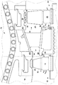
ここで図1を参照すると、その全体を参照符号10で示した例示的なタービンエンジンエンジンの部分が示されている。タービン10は、燃焼器の列(この図には図示せず)によって発生された高温ガスを受け、その高温ガスは後述するように環状の高温ガス流路34に沿って送給される。タービン段12、22は、環状の高温ガス流路34に沿って配置される。各このような段は、複数の円周方向に間隔を置いて配置されたロータブレードすなわちバケットと固定シュラウド組立体とを備えたロータ組立体を含む。各段はまた、回転ブレードの先端と固定シュラウドとの間の高温ガスの通路をシールするためのシール組立体を含む。例えば、図示するように、段12は、複数の円周方向に間隔を置いて配置されたブレード16と、固定シュラウド組立体18と、回転ブレード16と固定シュラウド18との界接面において係合するシール組立体20とを備えたロータ組立体14を含む。同様に、段22は、複数の円周方向に間隔を置いて配置されたブレード26と、固定シュラウド組立体28と、回転ブレード26と固定シュラウド28との界接面において係合するシール組立体30とを備えたロータ組立体24を含む。
Referring now to FIG. 1, a portion of an exemplary turbine engine engine, generally designated by the
一般的に、より高次のタービン段においては、各回転ブレードすなわちバケットは、その先端に部分シュラウドを有する場合があり、隣接して配置したシュラウド付きブレードは、連続した回転リングを形成するようになる。各バケットシュラウドは、図示するように1つ又はそれ以上のレール又はナイフ状隆起部を有することができる。この設計は、隣接するブレードの先端間で高温ガスが高温で漏洩するのを防止するより良好なシールを形成する。このようなタービン段は、これ以降はシュラウド式の段と呼ぶ。図1に示す実施においては、ロータ組立体24は、シュラウド式の段であり、各ブレード26は、その先端に部分シュラウド32を含む。これと対照的に、段12は、ロータ組立体14上に取付けられた剥き出しのブレード16を含む非シュラウド式の段として図示している。後で分かるであろうが、提案したシール組立体及び本シール方法は、非シュラウド式だけでなくシュラウド式のタービン段にも使用することができる。
In general, in higher order turbine stages, each rotating blade or bucket may have a partial shroud at its tip so that adjacent shrouded blades form a continuous rotating ring. Become. Each bucket shroud may have one or more rails or knife-like ridges as shown. This design forms a better seal that prevents hot gases from leaking at high temperatures between the tips of adjacent blades. Such turbine stages are hereinafter referred to as shroud stages. In the implementation shown in FIG. 1, the
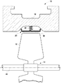
図2は、図1に示す非シュラウド式のタービン段12に使用した本方法による例示的なシール機構の実施形態を示す。図2は、円周方向が紙面の平面に対して垂直である、段12の部分断面図を表す。ロータブレード16は、燃焼器(この図には図示せず)からの高温ガス流を受けたとき軸線40の周りで回転する。シュラウド組立体18は、ブレード16を囲み、かつ軸線40とほぼ同軸である。ブレード16とシュラウド18との界接面において係合したシール組立体20には、後で説明するコンプライアント・シール機構が組み入れられる。
FIG. 2 illustrates an exemplary sealing mechanism embodiment according to the present method used in the
コンプライアント・シール組立体20は、大まかに言って硬質被覆シール表面36とバイアス部材38とを含む。硬質被覆シール先端表面36は、ブレード16の先端に接近した位置に配置される。ブレード先端と硬質皮膜との間の間隙は、エンジン間隙過渡プロフィールに基づいて設定される。表面36は、一般的に少なくとも熱的過渡期間中(つまり、回転及び固定構成部品間の異なる熱膨張の期間中)にブレード16の先端が該表面36に摺擦することによって生じる摩耗に対して実質的に耐性がある酸化アルミニウム(Al2O3)或いは硬質金属又はサーメット皮膜(トリバロイ(triballoy)・コバルト系のWC・CoCr、炭化Cr・NiCr)のような硬質セラミック材料で作られる。
The
バイアス部材38は、シール表面36とシュラウド組立体18の内周面との間に配置される。バイアス部材38は、本質的に必要な度合の弾性を示すバイアス要素を含む。効果的なシールを得るために、耐摩耗性表面36は、バイアス要素に予荷重を与えることによってブレード16に向かってバイアスされて、少なくともタービンの特定の運転フェーズ時に該シール表面36をブレード16の先端に対して付勢する。熱的過渡段階の間のような、ブレード16の先端と硬質被覆表面36との間で起こりがちなあらゆる接触又は摺擦時に、バイアス部材38は、ブレード16の先端が硬質被覆表面36に接触することによって生じる荷重に応じて圧縮される傾向がある。その結果、シュラウド表面36の材料摩耗が減少する。ブレード先端とシュラウドとの間の正常な間隙は、熱的安定段階に達すると回復される。提案した機構は、最大95%までのコンプライアンス性を達成するのに役立つことができると推定される。このことは、固定及び回転構成部品間の100ミリメートル(mm)の半径方向の干渉の場合に、侵入の95mmが、コンプライアント部材38の圧縮によって吸収され、また5mmが、ブレード材料のほぼ無視し得る摩耗である硬質被覆表面36の摩耗によって吸収されることを意味する。
The
本明細書で用いる場合、「バイアス」又は「バイアスさせる」という用語は、それぞれ「付勢」又は「付勢する」或いは「エネルギー付与」又は「エネルギー付与する」ことを意味しようとするものであることに留意されたい。後述するように、本説明におけるバイアス部材又は要素の役割は、ある程度の荷重又は力をシール表面に与えることである。しかし、この力は、剛性のシール表面により生じることになる力よりも著しく小さいので、摺擦接触が生じた時に回転ブレードに作用する荷重力は低下する。このバイアス又はエネルギー付与作用は、組立体がさらにコンプライアントになり、シール表面の位置で良好なシールを形成しながら摩耗を減少させることを可能にする。 As used herein, the term “bias” or “bias” is intended to mean “energize” or “energize” or “energize” or “energize” respectively. Please note that. As will be described later, the role of the biasing member or element in this description is to provide a certain load or force to the seal surface. However, this force is significantly smaller than the force that would be generated by the rigid seal surface, so the load force acting on the rotating blade when sliding contact occurs is reduced. This biasing or energizing action allows the assembly to become more compliant and reduce wear while forming a good seal at the seal surface location.
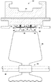
図3は、全体を参照符号22で示す、シュラウド式のタービン段におけるコンプライアント・シール組立体30の例示的な実施を示す。この図は、円周方向が紙面の平面に対して垂直である部分断面図を表す。先に述べたように、各ブレード26は、その先端に部分シュラウド構造体32を有する。隣接して配置したブレードのシュラウド付き先端32は、内側又は回転シュラウドとも呼ばれる実質的に連続した回転内側リングを形成する。固定シュラウド28は、ロータ軸線46とほぼ同軸であり、外側又は固定シュラウドと呼ばれる連続した外側リングを形成する。
FIG. 3 illustrates an exemplary implementation of a
ブレード26の先端における部分シュラウド32は、その数が一般的には2つであるレール又はナイフエッジ44から成る。内側シュラウド上のナイフエッジ44は、半径方向外向きに向いた実質的に連続した円周方向レールを形成する。外側シュラウドの内周面は、半径方向内向きに向いた複数の連続したナイフエッジ42を有する。内側シュラウド上のナイフエッジは、外側シュラウド上のナイフエッジと噛合って、図に示すようなラビリンス構造を形成する。図3に示す実施形態によると、コンプライアント・シール30は、外側シュラウド上の2つの連続ナイフエッジ間に配置される。非シュラウド式の段の場合のシール組立体と同様に、シュラウド式のタービン段の場合の各コンプライアント・シール組立体30は、内側シュラウド上のナイフエッジ44に近接して配置された硬質被覆表面36と、硬質被覆表面36と外側シュラウド28との間に配置された部分弾性バイアス部材38とを含む。内側シュラウド32と外側シュラウド28との間の高温ガス通路のシール作用は、バイアス部材38に予荷重を与えて硬質被覆表面36を内側シュラウド32上のナイフエッジ44に対して付勢することによって行われる。
The
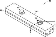
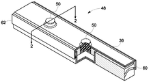
図4は、バイアス部材としてばねプランジャを用いた、本方法の態様によるコンプライアント・シール組立体48の1つの実施形態の斜視図を示す。図4は、シール組立体の1つのセグメントを示す。一般的に、シール組立体は、互いに隣接して組み立てられてリングを形成する多数のこのようなセグメントを含む。バイアス部材は、裏当て58上に配置された1つ又はそれ以上のばねプランジャ50を含む。このようなバイアス要素は、シュラウドの周面の周りで互いに一直線になった又はオフセットした状態にすることができることに留意されたい。さらに、バイアス要素は、異なる剛性又は機械特性を有することができる。ばねプランジャ50は、ばねボタンの形態で裏当て58の上方に突出する。実際には、図4に示す組立体は、それに対して該組立体が適合する外側シュラウドの外形とそれに向かってシール組立体が付勢されるブレード又は内側シュラウドの外形とに沿った弓形形状を有することができる。
FIG. 4 shows a perspective view of one embodiment of a
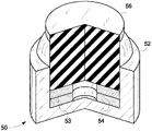
次に図5を参照すると、図4に示す矢印1で表した平面に沿って切断した断面で、図4に示すばねプランジャを示す部分断面斜視図が示されている。ばねプランジャ50は、図に符号53、54として表した、積重ね構成の複数のばね座金を備えたバイアス要素を含む。ばね座金53、54は、一般的にそれに限定されないが、中でも合金鋼又はニッケル基合金を含む耐熱性及び耐クリープ性金属合金を含む。一般的に、タービン段における運転温度がより高い場合には、ばね座金としては、より高位の貴金属が一層好適であるといえる。ばね座金53、54は、図4に示す裏当て58上に又はその内部に受けられたエンクロージャ52内に配置される。ばねプランジャはさらに、エンクロージャ52から外に突出したボタン56を含む。
Next, referring to FIG. 5, there is shown a partial cross-sectional perspective view showing the spring plunger shown in FIG. 4, which is a cross section cut along the plane represented by the
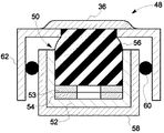
図6は、ばねプランジャ50を通る切断断面を示す、シール組立体48の部分断面斜視図を示す。図7は、図6に示す矢印2で表した平面に沿って切断した、ばねプランジャ50を通る断面の断面図である。ここで図6及び図7を参照すると、ボックス形状のスカート62が、突出ボタン56の上部に配置されている。底部で開口したスカート62は、ばねプランジャ50によってばね荷重が加えられており、半径方向に可撓性である。裏当て58とスカート62との間の間隙は、ばね座金の数及び構成とエンクロージャ52の高さとに応じて決まる。スカート62と裏当て58との間を高温ガスが通過する可能性を防止するために、スカート52と裏当て58との界接面にセラミック・ロープシールのような補助シール要素60を係合させることができる。硬質被覆先端表面36は、スカート62の外面上に配置され、またブレードの先端又はレールのような回転構成部品に近接して配置される。
FIG. 6 shows a partial cross-sectional perspective view of the
本方法によりコンプライアントにシールするための機構の別の実施形態は、バイアス要素として波形ばねを含むバイアス部材を使用する。図8は、波形ばね装置を使用したコンプライアント・シール組立体の例示的な実施形態を示す分解斜視図である。コンプライアント・シール組立体は、タービンエンジンの大きさに応じて、完全リング又は複数のセグメントを含むことができる。 Another embodiment of a mechanism for sealing compliantly by the method uses a biasing member that includes a wave spring as a biasing element. FIG. 8 is an exploded perspective view illustrating an exemplary embodiment of a compliant seal assembly using a wave spring device. The compliant seal assembly can include a complete ring or multiple segments, depending on the size of the turbine engine.
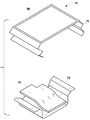
ここで図8を参照すると、全体を参照符号64で表したコンプライアント・シール組立体のセグメントは、バイアス要素としての波形ばね70と硬質被覆先端表面36とを含む。セグメント当たりの波の数、波の幅及び波の高さは、主として必要な半径方向コンプライアンスと波形ばねの材料の弾性とに応じて決まる。波形ばね材料は、それに限定されないが、中でも、合金鋼又はニッケル基合金を含む耐高温性及び耐クリープ性合金を含む。波形ばね70は、ボックスのようなエンクロージャ内部に配置される。エンクロージャは、上部半体66と下部半体68とを含み、波形ばね70は、この2つの半体間に配置される。1つの特定の製造方式では、波形ばね70は、エンクロージャの上部半体66にスポット溶接される。好ましくは上述のようなセラミック材料を含む先端表面36は、エンクロージャの上部半体66の外面上に配置される。先端表面36は、過渡段階の間に、波形ばね70が半径方向に圧縮された状態でブレードの先端又はレールに対して摺擦して、先端表面36の摩耗を最小にする。図示した実施形態では、エンクロージャの上部半体66の端縁は、下部半体68の端縁内に摺動挿入されるか又は下部半体68の端縁と相互にかみ合わされる。エンクロージャの上部半体66と下部半体68との間の高温ガスの通過は、補助シール部材72によってシールされる。補助シール部材72は、端縁においてエンクロージャの上部半体と下部半体との界接面に配置されたセラミック・ロープシールを含むことができる。
Referring now to FIG. 8, the segment of the compliant seal assembly, generally designated by
図9は、バイアス要素として波形ばねを有するコンプライアント・シール組立体用の別の構成の分解斜視図を示す。この構成では、エンクロージャの上部半体76は、その2つの端縁において、図9に示すようなベローズ状の構造又はアコーディオン形状の構成を含む。このアコーディオン形状の構成は、波形ばね70と共同してボックスの上部半体76と下部半体78との間での高温ガスの通過を防止する望ましい可撓性シール作用を行う。ベローズ状の構造は、タービンシュラウドの固有半径又は曲率を可能にするスリットを有することができる。効果的なシール作用のためには、アコーディオン形状の構成を含むボックスの半径方向コンプライアンスは、一般的に波形ばねの半径方向コンプライアンスよりも低い。
FIG. 9 shows an exploded perspective view of another configuration for a compliant seal assembly having a wave spring as a biasing element. In this configuration, the
提案した方法の上述の実施形態は、タービン又は類似の機械における回転及び固定構成部品間のガス流路の効果的なシール作用を行うと同時に、回転構成部品及びシールのアブレイダブル材料の摩耗を著しく減少させる。しかしながら、上述の実施形態は、タービン段に対する使用に限定されるものではない。提案したシール組立体及びその中に組み入れた方法はまた、圧縮機段又は段間のノズルの内径においてさえ使用することができる。その上、この構成は、ブラシシール構成、特に内側回転要素又は要素の組(例えば、タービンブレード)が上述のように部分シュラウド付きである場合のブラシシール構成に優る明確な利点をもたらす。 The above-described embodiments of the proposed method provide effective sealing of the gas flow path between rotating and stationary components in a turbine or similar machine, while at the same time reducing wear of rotating components and seal abradable material. Reduce significantly. However, the above-described embodiments are not limited to use with turbine stages. The proposed seal assembly and the method incorporated therein can also be used even at the inner diameter of the compressor stages or nozzles between stages. Moreover, this configuration provides distinct advantages over brush seal configurations, particularly where the inner rotating element or set of elements (eg, turbine blades) is partially shrouded as described above.
上述の方法は、タービン及び他の機械内の他の環境又は位置にも同様に用いることができることに留意されたい。例えば、上述の構成は、上述のようにタービンブレードすなわちバケットシールにだけでなくシャフトシールにも用いることができる。同様に、本明細書に述べたシール構成のコンプライアント構造は、図1に符号80で示したエンジェルウィングのようなタービンの段間において使用することができる。コンプライアント・シールは、図1に参照符号82で示した位置に配置することができる。
Note that the method described above can be used for other environments or locations within turbines and other machines as well. For example, the configuration described above can be used for shaft seals as well as turbine blades or bucket seals as described above. Similarly, the compliant construction of the seal configuration described herein can be used between turbine stages, such as the angel wing shown at 80 in FIG. The compliant seal can be placed in the position indicated by
本明細書では本発明の一部の特徴のみを例示しかつ説明してきたが、当業者は多くの改良及び変更に想到するであろう。特許請求の範囲に記載した参照符号は、本発明の技術的範囲を狭めるのではなくてそれらを容易に理解するためのものである。 Although only certain features of the invention have been illustrated and described herein, those skilled in the art will envision many improvements and modifications. Reference signs in the claims are not to narrow the technical scope of the invention but to facilitate understanding thereof.
10 タービン
12、22 タービン段
14、24 ロータ組立体
16、26 回転ブレード
18、28 固定シュラウド組立体
20、30 シール組立体
32 部分シュラウド構造体
34 高温ガス流路
80 エンジェルウィング
DESCRIPTION OF
Claims (10)
前記複数のブレード(16、26)の先端に物理的に近接した位置で該シール組立体(20、30)の先端として配置された実質的耐摩耗性表面(36)と、
前記実質的耐摩耗性表面(36)と前記固定ハウジング(18、28)との中間に配置(38)されたバイアス部材(38)と、を含み、
前記耐摩耗性表面(36)が、前記複数のブレード(16、26)の先端に向かってバイアスされている、
シール組立体(20、30)。 Seal assembly (20, 30) for a turbomachine (10) including a stationary housing (18, 28) and a plurality of blades (16, 26) mounted for rotation about an axis (40, 46) Because
A substantially wear resistant surface (36) disposed as a tip of the seal assembly (20, 30) at a location physically proximate to the tips of the plurality of blades (16, 26);
A biasing member (38) disposed (38) intermediate the substantially wear-resistant surface (36) and the stationary housing (18, 28);
The wear resistant surface (36) is biased toward the tips of the plurality of blades (16, 26);
Seal assembly (20, 30).
エンクロージャ(52)と、
前記エンクロージャ(52)内部に配置されたバイアス要素と、
前記実質的耐摩耗性表面(36)上に配置された突出ボタン(56)と、をさらに含む、
請求項1記載のシール組立体(20、30)。 The bias member (38) includes a plurality of spring plungers (50), each spring plunger (50) being
An enclosure (52);
A biasing element disposed within the enclosure (52);
A protruding button (56) disposed on the substantially wear-resistant surface (36);
The seal assembly (20, 30) according to claim 1.
ボックス形状を有しかつその底部で開口している、前記裏当て(58)上に配置されたスカート(62)と、
前記スカート(62)と前記裏当て(58)との界接面に配置された補助シール要素(60)と、
をさらに含む、請求項5記載のシール組立体(20、30)。 A backing (58) supporting the spring plunger (50);
A skirt (62) disposed on the backing (58) having a box shape and opening at the bottom thereof;
An auxiliary sealing element (60) disposed at the interface between the skirt (62) and the backing (58);
The seal assembly (20, 30) of claim 5, further comprising:
Applications Claiming Priority (2)
| Application Number | Priority Date | Filing Date | Title |
|---|---|---|---|
| US10/813,102 US7435049B2 (en) | 2004-03-30 | 2004-03-30 | Sealing device and method for turbomachinery |
| US10/813,102 | 2004-03-30 |
Publications (2)
| Publication Number | Publication Date |
|---|---|
| JP2005291205A true JP2005291205A (en) | 2005-10-20 |
| JP4926410B2 JP4926410B2 (en) | 2012-05-09 |
Family
ID=34887692
Family Applications (1)
| Application Number | Title | Priority Date | Filing Date |
|---|---|---|---|
| JP2005094395A Expired - Fee Related JP4926410B2 (en) | 2004-03-30 | 2005-03-29 | Sealing apparatus and method for turbomachine |
Country Status (4)
| Country | Link |
|---|---|
| US (1) | US7435049B2 (en) |
| EP (1) | EP1582700B1 (en) |
| JP (1) | JP4926410B2 (en) |
| DE (1) | DE602005007408D1 (en) |
Cited By (5)
| Publication number | Priority date | Publication date | Assignee | Title |
|---|---|---|---|---|
| JP2010261351A (en) * | 2009-05-01 | 2010-11-18 | Hitachi Ltd | Seal structure and control method |
| JP2013256944A (en) * | 2012-06-08 | 2013-12-26 | General Electric Co <Ge> | Shroud for rotary machine, and method of assembling the same |
| WO2014038079A1 (en) * | 2012-09-10 | 2014-03-13 | 株式会社 日立製作所 | Turbo machine |
| JP2020051308A (en) * | 2018-09-26 | 2020-04-02 | 本田技研工業株式会社 | Turbofan engine |
| US11092026B2 (en) | 2016-03-25 | 2021-08-17 | Mitsubishi Power, Ltd. | Rotary machine |
Families Citing this family (75)
| Publication number | Priority date | Publication date | Assignee | Title |
|---|---|---|---|---|
| DE102005013798A1 (en) * | 2005-03-24 | 2006-09-28 | Alstom Technology Ltd. | Heat release segment for sealing a flow channel of a flow rotary machine |
| US20070228664A1 (en) * | 2006-03-31 | 2007-10-04 | Krishnamurthy Anand | Mechanical seals and methods of making |
| US8568091B2 (en) * | 2008-02-18 | 2013-10-29 | United Technologies Corporation | Gas turbine engine systems and methods involving blade outer air seals |
| US8534995B2 (en) * | 2009-03-05 | 2013-09-17 | United Technologies Corporation | Turbine engine sealing arrangement |
| GB2486488A (en) | 2010-12-17 | 2012-06-20 | Ge Aviat Systems Ltd | Testing a transient voltage protection device |
| US9145785B2 (en) * | 2011-03-04 | 2015-09-29 | General Electric Company | Aerodynamic seal assemblies for turbo-machinery |
| US8944756B2 (en) * | 2011-07-15 | 2015-02-03 | United Technologies Corporation | Blade outer air seal assembly |
| US9109458B2 (en) | 2011-11-11 | 2015-08-18 | United Technologies Corporation | Turbomachinery seal |
| US8985938B2 (en) * | 2011-12-13 | 2015-03-24 | United Technologies Corporation | Fan blade tip clearance control via Z-bands |
| US9103224B2 (en) | 2011-12-29 | 2015-08-11 | General Electric Company | Compliant plate seal for use with rotating machines and methods of assembling a rotating machine |
| CA2805490C (en) * | 2012-02-10 | 2015-02-03 | Syncrude Canada Ltd. | Self-adjusting liner for centrifugal pumps |
| US9228447B2 (en) | 2012-02-14 | 2016-01-05 | United Technologies Corporation | Adjustable blade outer air seal apparatus |
| KR101906949B1 (en) | 2012-02-29 | 2018-10-11 | 한화에어로스페이스 주식회사 | A turbine seal assembly and a turbine apparatus comprising the same |
| US9255642B2 (en) * | 2012-07-06 | 2016-02-09 | General Electric Company | Aerodynamic seals for rotary machine |
| US9200530B2 (en) * | 2012-07-20 | 2015-12-01 | United Technologies Corporation | Radial position control of case supported structure |
| US9587746B2 (en) | 2012-07-31 | 2017-03-07 | General Electric Company | Film riding seals for rotary machines |
| US9528376B2 (en) | 2012-09-13 | 2016-12-27 | General Electric Company | Compressor fairing segment |
| US9752592B2 (en) | 2013-01-29 | 2017-09-05 | Rolls-Royce Corporation | Turbine shroud |
| EP2961941B1 (en) * | 2013-02-26 | 2020-02-19 | Rolls-Royce Corporation | Apparatuses comprising a pivotable turbine vane |
| EP2971577B1 (en) | 2013-03-13 | 2018-08-29 | Rolls-Royce Corporation | Turbine shroud |
| EP2881667B1 (en) * | 2013-10-11 | 2017-04-26 | General Electric Technology GmbH | Helmholtz damper with air cooled seal for a gas turbine |
| US9909428B2 (en) | 2013-11-26 | 2018-03-06 | General Electric Company | Turbine buckets with high hot hardness shroud-cutting deposits |
| US10082085B2 (en) | 2013-12-17 | 2018-09-25 | Rolls-Royce North American Technologies Inc. | Seal for gas turbine engines |
| US9957826B2 (en) | 2014-06-09 | 2018-05-01 | United Technologies Corporation | Stiffness controlled abradeable seal system with max phase materials and methods of making same |
| US9945243B2 (en) | 2014-10-14 | 2018-04-17 | Rolls-Royce Corporation | Turbine shroud with biased blade track |
| US10190434B2 (en) | 2014-10-29 | 2019-01-29 | Rolls-Royce North American Technologies Inc. | Turbine shroud with locating inserts |
| CA2915246A1 (en) | 2014-12-23 | 2016-06-23 | Rolls-Royce Corporation | Turbine shroud |
| CA2915370A1 (en) | 2014-12-23 | 2016-06-23 | Rolls-Royce Corporation | Full hoop blade track with axially keyed features |
| EP3045674B1 (en) | 2015-01-15 | 2018-11-21 | Rolls-Royce Corporation | Turbine shroud with tubular runner-locating inserts |
| CA2916710A1 (en) | 2015-01-29 | 2016-07-29 | Rolls-Royce Corporation | Seals for gas turbine engines |
| US10100649B2 (en) | 2015-03-31 | 2018-10-16 | Rolls-Royce North American Technologies Inc. | Compliant rail hanger |
| CA2925588A1 (en) | 2015-04-29 | 2016-10-29 | Rolls-Royce Corporation | Brazed blade track for a gas turbine engine |
| CA2924866A1 (en) | 2015-04-29 | 2016-10-29 | Daniel K. Vetters | Composite keystoned blade track |
| FR3036436B1 (en) * | 2015-05-22 | 2020-01-24 | Safran Ceramics | TURBINE RING ASSEMBLY WITH HOLDING BY FLANGES |
| US9951632B2 (en) | 2015-07-23 | 2018-04-24 | Honeywell International Inc. | Hybrid bonded turbine rotors and methods for manufacturing the same |
| US10060280B2 (en) | 2015-10-15 | 2018-08-28 | United Technologies Corporation | Turbine cavity sealing assembly |
| DE112015006777T5 (en) * | 2015-10-27 | 2018-05-03 | Mitsubishi Heavy Industries, Ltd. | rotary engine |
| US10240476B2 (en) | 2016-01-19 | 2019-03-26 | Rolls-Royce North American Technologies Inc. | Full hoop blade track with interstage cooling air |
| US9970310B2 (en) * | 2016-01-21 | 2018-05-15 | United Technologies Corporation | System and method for an assembled ring shroud |
| US10247029B2 (en) * | 2016-02-04 | 2019-04-02 | United Technologies Corporation | Method for clearance control in a gas turbine engine |
| US10443424B2 (en) | 2016-03-16 | 2019-10-15 | United Technologies Corporation | Turbine engine blade outer air seal with load-transmitting carriage |
| US10563531B2 (en) | 2016-03-16 | 2020-02-18 | United Technologies Corporation | Seal assembly for gas turbine engine |
| US10132184B2 (en) * | 2016-03-16 | 2018-11-20 | United Technologies Corporation | Boas spring loaded rail shield |
| US10107129B2 (en) | 2016-03-16 | 2018-10-23 | United Technologies Corporation | Blade outer air seal with spring centering |
| US10443616B2 (en) | 2016-03-16 | 2019-10-15 | United Technologies Corporation | Blade outer air seal with centrally mounted seal arc segments |
| US10513943B2 (en) | 2016-03-16 | 2019-12-24 | United Technologies Corporation | Boas enhanced heat transfer surface |
| US10337346B2 (en) | 2016-03-16 | 2019-07-02 | United Technologies Corporation | Blade outer air seal with flow guide manifold |
| US10138749B2 (en) | 2016-03-16 | 2018-11-27 | United Technologies Corporation | Seal anti-rotation feature |
| US10422240B2 (en) | 2016-03-16 | 2019-09-24 | United Technologies Corporation | Turbine engine blade outer air seal with load-transmitting cover plate |
| US10161258B2 (en) * | 2016-03-16 | 2018-12-25 | United Technologies Corporation | Boas rail shield |
| US10422241B2 (en) | 2016-03-16 | 2019-09-24 | United Technologies Corporation | Blade outer air seal support for a gas turbine engine |
| US10415414B2 (en) | 2016-03-16 | 2019-09-17 | United Technologies Corporation | Seal arc segment with anti-rotation feature |
| US10138750B2 (en) | 2016-03-16 | 2018-11-27 | United Technologies Corporation | Boas segmented heat shield |
| US10408074B2 (en) | 2016-04-25 | 2019-09-10 | United Technologies Corporation | Creep resistant axial ring seal |
| US10415415B2 (en) | 2016-07-22 | 2019-09-17 | Rolls-Royce North American Technologies Inc. | Turbine shroud with forward case and full hoop blade track |
| US10287906B2 (en) | 2016-05-24 | 2019-05-14 | Rolls-Royce North American Technologies Inc. | Turbine shroud with full hoop ceramic matrix composite blade track and seal system |
| US10408075B2 (en) * | 2016-08-16 | 2019-09-10 | General Electric Company | Turbine engine with a rim seal between the rotor and stator |
| US10851712B2 (en) | 2017-06-27 | 2020-12-01 | General Electric Company | Clearance control device |
| US10392957B2 (en) | 2017-10-05 | 2019-08-27 | Rolls-Royce Corporation | Ceramic matrix composite blade track with mounting system having load distribution features |
| US10933469B2 (en) | 2018-09-10 | 2021-03-02 | Honeywell International Inc. | Method of forming an abrasive nickel-based alloy on a turbine blade tip |
| CN109707468B (en) * | 2018-12-29 | 2022-03-15 | 中国科学院工程热物理研究所 | Be applied to high-efficient structure of obturating between static machine casket |
| US11149563B2 (en) * | 2019-10-04 | 2021-10-19 | Rolls-Royce Corporation | Ceramic matrix composite blade track with mounting system having axial reaction load distribution features |
| US11459902B1 (en) * | 2020-01-07 | 2022-10-04 | United States Of America As Represented By The Secretary Of The Air Force | Seal for a wave rotor disk engine |
| US11773741B2 (en) * | 2021-06-09 | 2023-10-03 | General Electric Company | Compliant shroud designs with variable stiffness |
| CN117917503A (en) * | 2022-10-20 | 2024-04-23 | 通用电气公司 | Turbine engine with rotor seal retraction mechanism |
| US12006829B1 (en) | 2023-02-16 | 2024-06-11 | General Electric Company | Seal member support system for a gas turbine engine |
| US12486779B2 (en) | 2023-03-08 | 2025-12-02 | General Electric Company | Seal support assembly for a turbine engine |
| US12116896B1 (en) | 2023-03-24 | 2024-10-15 | General Electric Company | Seal support assembly for a turbine engine |
| US12215587B2 (en) | 2023-03-24 | 2025-02-04 | General Electric Company | Seal support assembly for a turbine engine |
| US12421861B2 (en) | 2023-03-24 | 2025-09-23 | General Electric Company | Seal support assembly for a turbine engine |
| US12372002B2 (en) | 2023-03-24 | 2025-07-29 | General Electric Company | Seal support assembly for a turbine engine |
| US12416243B2 (en) | 2023-03-24 | 2025-09-16 | General Electric Company | Seal support assembly for a turbine engine |
| US12241375B2 (en) | 2023-03-24 | 2025-03-04 | General Electric Company | Seal support assembly for a turbine engine |
| US12215588B2 (en) | 2023-03-27 | 2025-02-04 | General Electric Company | Seal assembly for a gas turbine engine |
| US12326089B2 (en) | 2023-04-24 | 2025-06-10 | General Electric Company | Seal assembly for a gas turbine engine |
Citations (5)
| Publication number | Priority date | Publication date | Assignee | Title |
|---|---|---|---|---|
| JPS566006A (en) * | 1979-06-27 | 1981-01-22 | United Technologies Corp | Outer sealant |
| JPS57157002A (en) * | 1981-03-25 | 1982-09-28 | Hitachi Ltd | Clearance controlling device for gas turbine |
| JPH03141804A (en) * | 1989-09-08 | 1991-06-17 | General Electric Co <Ge> | Clearance control device |
| JPH07174001A (en) * | 1993-12-20 | 1995-07-11 | Toshiba Corp | Blade tip clearance controller |
| JP2001303904A (en) * | 2000-04-24 | 2001-10-31 | Mitsubishi Heavy Ind Ltd | Gas turbine moving blade |
Family Cites Families (9)
| Publication number | Priority date | Publication date | Assignee | Title |
|---|---|---|---|---|
| US4135851A (en) * | 1977-05-27 | 1979-01-23 | The United States Of America As Represented By The Administrator Of The National Aeronautics And Space Administration | Composite seal for turbomachinery |
| US4576548A (en) * | 1984-01-17 | 1986-03-18 | Westinghouse Electric Corp. | Self-aligning static seal for gas turbine stator vanes |
| US5108116A (en) * | 1991-05-31 | 1992-04-28 | Allied-Signal Inc. | Laminated finger seal with logarithmic curvature |
| US5961125A (en) * | 1997-10-02 | 1999-10-05 | General Electric Company | Brush seal for use on rough rotating surfaces |
| US5941685A (en) * | 1997-10-14 | 1999-08-24 | General Electric Company | Brush seal for use on bumpy rotating surfaces |
| DE10196832T1 (en) * | 2000-11-06 | 2003-11-13 | Advanced Components & Material | Spring brush casing arrangement for compressors of gas turbine engines |
| US6439844B1 (en) * | 2000-12-11 | 2002-08-27 | General Electric Company | Turbine bucket cover and brush seal |
| US6431827B1 (en) * | 2000-12-21 | 2002-08-13 | General Electric Company | Bucket tip brush seals in steam turbines and methods of installation |
| US6547522B2 (en) * | 2001-06-18 | 2003-04-15 | General Electric Company | Spring-backed abradable seal for turbomachinery |
-
2004
- 2004-03-30 US US10/813,102 patent/US7435049B2/en active Active
-
2005
- 2005-03-23 DE DE602005007408T patent/DE602005007408D1/en not_active Expired - Lifetime
- 2005-03-23 EP EP05251810A patent/EP1582700B1/en not_active Ceased
- 2005-03-29 JP JP2005094395A patent/JP4926410B2/en not_active Expired - Fee Related
Patent Citations (5)
| Publication number | Priority date | Publication date | Assignee | Title |
|---|---|---|---|---|
| JPS566006A (en) * | 1979-06-27 | 1981-01-22 | United Technologies Corp | Outer sealant |
| JPS57157002A (en) * | 1981-03-25 | 1982-09-28 | Hitachi Ltd | Clearance controlling device for gas turbine |
| JPH03141804A (en) * | 1989-09-08 | 1991-06-17 | General Electric Co <Ge> | Clearance control device |
| JPH07174001A (en) * | 1993-12-20 | 1995-07-11 | Toshiba Corp | Blade tip clearance controller |
| JP2001303904A (en) * | 2000-04-24 | 2001-10-31 | Mitsubishi Heavy Ind Ltd | Gas turbine moving blade |
Cited By (7)
| Publication number | Priority date | Publication date | Assignee | Title |
|---|---|---|---|---|
| JP2010261351A (en) * | 2009-05-01 | 2010-11-18 | Hitachi Ltd | Seal structure and control method |
| JP2013256944A (en) * | 2012-06-08 | 2013-12-26 | General Electric Co <Ge> | Shroud for rotary machine, and method of assembling the same |
| WO2014038079A1 (en) * | 2012-09-10 | 2014-03-13 | 株式会社 日立製作所 | Turbo machine |
| JPWO2014038079A1 (en) * | 2012-09-10 | 2016-08-08 | 株式会社日立製作所 | Turbo machine |
| US11092026B2 (en) | 2016-03-25 | 2021-08-17 | Mitsubishi Power, Ltd. | Rotary machine |
| JP2020051308A (en) * | 2018-09-26 | 2020-04-02 | 本田技研工業株式会社 | Turbofan engine |
| JP6990639B2 (en) | 2018-09-26 | 2022-01-12 | 本田技研工業株式会社 | Turbofan engine |
Also Published As
| Publication number | Publication date |
|---|---|
| DE602005007408D1 (en) | 2008-07-24 |
| EP1582700A3 (en) | 2005-12-14 |
| EP1582700A2 (en) | 2005-10-05 |
| US7435049B2 (en) | 2008-10-14 |
| JP4926410B2 (en) | 2012-05-09 |
| EP1582700B1 (en) | 2008-06-11 |
| US20050220610A1 (en) | 2005-10-06 |
Similar Documents
| Publication | Publication Date | Title |
|---|---|---|
| JP4926410B2 (en) | Sealing apparatus and method for turbomachine | |
| US7857582B2 (en) | Abradable labyrinth tooth seal | |
| RU2319017C2 (en) | Ring seal and rotating mechanism of turbine | |
| EP2580498B1 (en) | Film riding pressure actuated leaf seal assembly | |
| CN103216277B (en) | Refreshable inter-stage becomes corner seal | |
| US8834106B2 (en) | Seal assembly for gas turbine engine | |
| EP2636853B1 (en) | Sealing assembly for use in a rotary machine | |
| US8740552B2 (en) | Low-ductility turbine shroud and mounting apparatus | |
| CN101148993B (en) | Methods and apparatus for fabricating turbine engines | |
| EP2495398B1 (en) | Aerodynamic seal assemblies for turbo-machinery | |
| US3423070A (en) | Sealing means for turbomachinery | |
| US8419356B2 (en) | Turbine seal assembly | |
| US5192185A (en) | Shroud liners | |
| CN1837581B (en) | Compliant seal and system and method therefor | |
| US20120230818A1 (en) | Airfoil and corresponding guide vane, blade, gas turbine and turbomachine | |
| US20060110248A1 (en) | Pattern for the surface of a turbine shroud | |
| EP3090140B1 (en) | Blade outer air seal with secondary air sealing | |
| EP1510655B1 (en) | Brush seal support | |
| JP2011241826A (en) | Seal assembly including plateau and concave portion in mating surface for seal tooth in turbine | |
| US9829007B2 (en) | Turbine sealing system | |
| JP2006105393A (en) | Compliant seal and its system and manufacturing method | |
| EP3409885B1 (en) | Deflection spring seal | |
| EP1712743A2 (en) | Turbine with an abradable seal between the rotor and a stationary component | |
| CN113167126B (en) | Secondary seal in a non-contact seal assembly | |
| EP3396114A1 (en) | Turbomachinery and corresponding method of operating |
Legal Events
| Date | Code | Title | Description |
|---|---|---|---|
| A621 | Written request for application examination |
Free format text: JAPANESE INTERMEDIATE CODE: A621 Effective date: 20080324 |
|
| A131 | Notification of reasons for refusal |
Free format text: JAPANESE INTERMEDIATE CODE: A131 Effective date: 20101005 |
|
| A601 | Written request for extension of time |
Free format text: JAPANESE INTERMEDIATE CODE: A601 Effective date: 20101224 |
|
| RD02 | Notification of acceptance of power of attorney |
Free format text: JAPANESE INTERMEDIATE CODE: A7422 Effective date: 20101224 |
|
| RD04 | Notification of resignation of power of attorney |
Free format text: JAPANESE INTERMEDIATE CODE: A7424 Effective date: 20101224 |
|
| A602 | Written permission of extension of time |
Free format text: JAPANESE INTERMEDIATE CODE: A602 Effective date: 20110105 |
|
| A131 | Notification of reasons for refusal |
Free format text: JAPANESE INTERMEDIATE CODE: A131 Effective date: 20110510 |
|
| A601 | Written request for extension of time |
Free format text: JAPANESE INTERMEDIATE CODE: A601 Effective date: 20110805 |
|
| A602 | Written permission of extension of time |
Free format text: JAPANESE INTERMEDIATE CODE: A602 Effective date: 20110811 |
|
| A521 | Request for written amendment filed |
Free format text: JAPANESE INTERMEDIATE CODE: A523 Effective date: 20111108 |
|
| TRDD | Decision of grant or rejection written | ||
| A01 | Written decision to grant a patent or to grant a registration (utility model) |
Free format text: JAPANESE INTERMEDIATE CODE: A01 Effective date: 20120110 |
|
| A01 | Written decision to grant a patent or to grant a registration (utility model) |
Free format text: JAPANESE INTERMEDIATE CODE: A01 |
|
| A61 | First payment of annual fees (during grant procedure) |
Free format text: JAPANESE INTERMEDIATE CODE: A61 Effective date: 20120208 |
|
| FPAY | Renewal fee payment (event date is renewal date of database) |
Free format text: PAYMENT UNTIL: 20150217 Year of fee payment: 3 |
|
| R150 | Certificate of patent or registration of utility model |
Free format text: JAPANESE INTERMEDIATE CODE: R150 |
|
| R250 | Receipt of annual fees |
Free format text: JAPANESE INTERMEDIATE CODE: R250 |
|
| R250 | Receipt of annual fees |
Free format text: JAPANESE INTERMEDIATE CODE: R250 |
|
| R250 | Receipt of annual fees |
Free format text: JAPANESE INTERMEDIATE CODE: R250 |
|
| LAPS | Cancellation because of no payment of annual fees |