JP2004209687A - Method and apparatus for integrally molding decorative member on trim component for vehicle - Google Patents
Method and apparatus for integrally molding decorative member on trim component for vehicle Download PDFInfo
- Publication number
- JP2004209687A JP2004209687A JP2002379064A JP2002379064A JP2004209687A JP 2004209687 A JP2004209687 A JP 2004209687A JP 2002379064 A JP2002379064 A JP 2002379064A JP 2002379064 A JP2002379064 A JP 2002379064A JP 2004209687 A JP2004209687 A JP 2004209687A
- Authority
- JP
- Japan
- Prior art keywords
- mold
- decorative member
- edge
- slide block
- resin
- Prior art date
- Legal status (The legal status is an assumption and is not a legal conclusion. Google has not performed a legal analysis and makes no representation as to the accuracy of the status listed.)
- Pending
Links
Images


Abstract
Description
【0001】
【発明の属する技術分野】
本発明は車両用内装部品に加飾部材を一体成形する方法及び装置に係り、特に、加飾部材の端部を基材に埋設させて外観商品性の向上を図った、車両用内装部品に加飾部材を一体成形する方法及び装置に関する。
【0002】
【従来の技術】
従来から、成形樹脂の一部に他の部材からなる加飾部材を一体成形する技術が知られている。例えば加飾部材を用いた成形樹脂の例としては、ドアライニングやサイドライニング等の自動車用内装ライニング部品や、その他成形された樹脂に部分的な加飾部材を用いたものが知られている。
【0003】
これらの加飾部材は、予め成形金型に装着した後で溶融樹脂を注入して、成形樹脂と加飾部材とを一体成形している。
具体的には、図10乃至図13で示すように、布等の加飾部材120をプリフォーム若しくは真空引きにより固定型102側に対して位置決めしてセットし、可動型101を固定型102側に移動させ、可動型101と固定型102により形成されたキャビティKに樹脂Jを注入し、成形品を形成していた。
【0004】
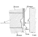
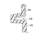
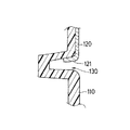
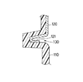
上記従来の成形方法では、加飾部材120の端縁処理を、可動型101側に設けられた木目込みバー103に沿わせて行っているので、加飾部材120が装着された後、製品の表面材110に溝部130が形成されることになる。そのため、図14に示すように、加飾部材120の端末部121が短い場合は、溝部130において下地樹脂が見えてしまっていた。或いは、図15に示すように、加飾部材120の端末部121が長い場合は、端末部121の折返しが見えてしまい、見栄えが悪くなるという不都合があった。
【0005】
このため、加飾部材120を精度良く裁断する必要があり手間がかかっていた。また、加飾部材120が精度良く裁断されていたとしても、配設時に位置がずれてしまうと、上記と同様の不具合が発生してしまうという問題があった。
【0006】
これを避けるため、溝130を狭くして商品性を向上させようとすると、金型の木目込みバー103自体を細くする必要があるが、このように木目込みバー103を細くすると、木目込みバー103が折れたり、破損するおそれがあった。
【0007】
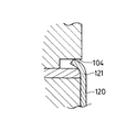
上記不都合を解決するために、図16または図17に示すように、金型に隙間104を形成し、この隙間104において加飾部材120の端末部121を保持して、加飾部材120がずれないようにした技術が提案されている。
【0008】
しかし、上記の技術では、加飾部材120の端末部121を金型側に設けられた隙間104に差し込む必要があるため、製造工程が煩雑になるという問題があった。また、加飾部材120が所定の寸法となるように精度良くカットする必要があり、手間がかかっていた。
【0009】
或いは、金型において、表皮材で覆われる領域の外周囲に進退可能なクランプ体を設け、表皮材の端末部を金型とクランプ体とで挟持し、表皮材で覆われた領域内に溶融樹脂を射出し、溶融樹脂の充満に伴い表皮材を可動型に設けられた刃部に押し付け、表皮材を切断させて溶融樹脂を表皮材の外側領域に流出させ、表皮材と樹脂を一体成形する技術が提案されている(例えば、特許文献1参照)。
【0010】
【特許文献1】
特開2000−141378号公報(第4頁、図6)
【0011】
上記技術によれば、金型に設けられた刃部が溶融樹脂の圧力及びその熱を利用して表皮材を所定位置でカットするので、表皮材端末部が溝内におさめられ、表皮材端末ラインの見栄えの良い成形品を形成することが可能となる。
【0012】
【発明が解決しようとする課題】
しかし、上記特許文献1の技術は、金型に刃部を設ける必要があるため、金型の加工に手間がかかるとともに、刃部の部分が破損しやすいという問題があった。また、表皮材が切断されることが必要であるため、表皮材の材質に制限が生じたり、溶融樹脂の射出圧の管理に手間がかかるという問題があった。
【0013】
本発明の目的は、加飾部材を備えた車両用内装部品において、端末ラインの外観が良好な加飾部材を簡単に製造することが可能な、車両用内装部品に加飾部材を一体成形する方法及び装置を提供することにある。
【0014】
【課題を解決するための手段】
前記課題は、本発明によれば、車両用内装部品に加飾部材を一体成形する方法において、前記加飾部材の加飾面と端末部との境界部を押さえるエッジが設けられた第1の金型と、該第1の金型に対向して配設され、前記エッジに係合可能な凹部が設けられた第2の金型との間に前記加飾部材を配設する工程と、前記第1の金型と第2の金型を型締めし、前記エッジと凹部との間で前記加飾部材の境界部を挟持する工程と、前記エッジと前記凹部を含んで形成される第1のキャビティに樹脂を注入し、該樹脂と前記加飾部材の端末部とを一体成形する工程と、前記第1の金型と第2の金型を離間させ、前記凹部と、前記一体成形された樹脂及び加飾部材との間に第2のキャビティを形成する工程と、前記第2のキャビティに樹脂を注入する工程と、前記第1の金型と第2の金型の間から成形品を取り出す工程と、を備えたことにより解決される。
【0015】
このように、本発明によれば、加飾部材の加飾面と端末部との境界部をエッジで押さえ、第1のキャビティに樹脂を注入して加飾部材の端末部と樹脂を一体成形し、さらに金型を離間させて第2のキャビティを形成し、第2のキャビティに樹脂を注入して成形することにより、加飾部材の端末部がそれぞれのキャビティにおいて成形された樹脂の中に埋入されるので、加飾部材の端末部が成形品表面から露見することなく、外観上良好な車両用内装部品を得ることが可能となる。
【0016】
また、前記課題は、本発明の車両用内装部品に加飾部材を一体成形する装置によれば、上下又は左右方向に型開きする金型内に加飾部材を配置して樹脂を注入し、該樹脂と前記加飾部材を一体成形する車両用内装部品に加飾部材を一体成形する装置において、前記金型は可動型と、該可動型に対向するスライドブロックと、該スライドブロックに隣接する固定型とを備え、前記可動型には前記加飾部材の加飾面と端末部との境界部を押さえるエッジが設けられ、前記スライドブロックには前記エッジに係合可能な凹部が設けられ、前記可動型のエッジと、前記可動型側へ向けてスライドされた前記スライドブロックの凹部と、前記固定型と、に囲まれて第1のキャビティが形成され、前記可動型と、前記固定型と、前記可動型から離間する方向にスライドされたスライドブロックと、に囲まれて第2のキャビティが形成される、ことにより解決される。
【0017】
このように、本発明の装置は、可動型に設けられたエッジと、スライドブロックに設けられた凹部で加飾部材の加飾面と端末部との境界部を押さえるように構成されており、従来の木目込みバーを用いないので、金型耐久性を向上させることが可能となる。
【0018】
なお、前記加飾部材の端末部の長さが略15mm以下、前記エッジの高さが略0.5〜5.0mm、前記第1のキャビティのクリアランスが略1.5〜3.5mmとなるようにすることにより、加飾部材の境界部がエッジと凹部との間で確実に保持される。また、上記寸法とすることにより、加飾部材の端末部が製品表面に出ることがなく高い商品性を得ることが可能となる。
【0019】
【発明の実施の形態】
以下、本発明の一実施の形態を図面に基づいて説明する。なお、以下に説明する部材,配置等は本発明を限定するものでなく、本発明の趣旨の範囲内で種々改変することができるものである。
【0020】
図1乃至図8は本発明の一実施例を示すものであり、図1は車両用内装部品の一例を示す斜視図、図2乃至図6は本発明に係る装置及び車両用内装部品の製造工程を示す説明図、図7は車両用内装部品の断面図、図8は金型の各部位の大きさを示す説明図である。
【0021】
本発明で形成される成形品は、布等の加飾部材を備えた車両用内装部品Sであり、例えば、図1に示すような自動車のドアライニングである。
【0022】
成形品を製造する装置は、図2に示すように、製品意匠面側に位置する第1の金型と、製品裏面側に位置する第2の金型とを備えて構成されている。金型としては、上下方向に型開きする金型、左右方向に型開きする金型のいずれの金型を用いても良い。
【0023】
第1の金型は可動型1であり、図示しない駆動機構等により可動自在に構成されている。駆動機構としては、油圧装置、空気圧装置、ばね式等の公知の手段を用いることができる。
【0024】
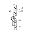
可動型1には、図2に示すように、金型の表面から突出するエッジ3が設けられている。エッジ3は、金型面をR形状に加工することにより形成されている。エッジ3は、可動型1とスライドブロック4との間で加飾部材20を挟持したときに、加飾部材20の加飾面22と端末部21との境界部23に沿うように形成されている。
【0025】
第2の金型は、一対の固定型2a,2bと、これら固定型2a,2bの間に位置するスライドブロック4から構成されている。固定型2a,2bは所望の型形状を備えており、また、固定型2a,2bを貫通する図示しない通路及びゲートが形成されている。そして、この通路及びゲートを介して、キャビティへ溶融状態の溶融樹脂(例えばポリプロピレン)が供給されるように構成されている。
【0026】
スライドブロック4は、図示しない駆動装置により、一対の固定型2a,2bの間でスライド可能に構成されている。なお、駆動機構としては、油圧装置、空気圧装置、ばね式等の公知の手段を用いることができる。
【0027】
スライドブロック4は、型締めしたときに、可動型1のエッジ3に係合可能な凹部5を備えている。凹部5には、可動型1とスライドブロック4との間で加飾部材20を挟持したときに、加飾部材20の端末部21が位置する。また、エッジ3が凹部5に押し付けられ、エッジ3と凹部5との間で、加飾部材20の加飾面22と端末部21との境界部23を挟持するように構成されている。
【0028】
スライドブロック4は、型締め時には、図3に示すように、可動型1側に移動して、前記したように可動型1との間で加飾部材20を挟持するとともに、可動型1と固定型2bとの間に第1のキャビティK1を形成する。また、スライドブロック4が可動型1から離間する方向にスライドしたときには、図5に示すように、可動型1、スライドブロック4、固定型2a,2b、との間に第2のキャビティK2が形成される。
【0029】
実際に成形品を製造しているときは、図5に示すように、第2のキャビティK2は、可動型1側に位置する製造途中の成形品30、スライドブロック4、固定型2a,2b、との間に形成される。製造途中の成形品30は、加飾部材20と、表面材10とから構成されているものである。
【0030】
なお、外観上良好な成形品を製造するために、加飾部材20の端末部21の長さ、可動型1及び固定型2a,2b、キャビティのサイズについて、次の大きさとすると良い。
【0031】
加飾部材20の端末部21の長さ、可動型1及び固定型2a,2b、或いは金型により形成されるキャビティのサイズについて、好適な例を図8に示している。図8に示す大きさにすることにより、加飾部材20の端末部21を、可動型1のエッジ3とスライドブロック4の凹部5との間で確実に保持することができ、また、成形後に加飾部材20の端末部21が製品表面に出ることなく、外観上好適な車両用内装部品Sを形成することが可能となるものである。
【0032】
可動型1のエッジ3の高さxは、略0.5〜5.0mmの範囲に形成されていると好適であり、より好ましくは2.0mmの高さとされていると好適である。
【0033】
さらに、スライドブロック4と可動型1との間に形成されるクリアランスy、すなわち、第1のキャビティのクリアランスyは、略1.5mm〜3.5mm、より好ましくは2.5mmとされていると好適である。そして、金型を上記大きさとした場合、加飾部材20の端末部21は15mm以下とされると好適である。
【0034】
なお、図9は加飾部材の端末部の状態について好ましくない例を示す参考図である。図9に示すように、エッジ3の高さや、加飾部材20の端末部21の長さが適正でない場合は、加飾部材20が好適に保持されなかたり、端末部21に浮きが発生してしまう。このため、上記したように、加飾部材の端末部の長さや、金型,キャビティのサイズを適切に調整することが望ましい。
【0035】
次に、上記構成からなる装置によって車両用内装部品Sを製造する工程について説明する。先ず、図2に示すように、金型が型開きされているときに、可動型1と固定型2a,2b及びスライドブロック4の間に、固定型2a,2b及びスライドブロック4に沿わせて加飾部材20を配設する。加飾部材20は、プリフォームしてセットされるか、或いは真空引き或いはロボットにより位置決めしてセットされる。
【0036】
次いで、図3に示すように、加飾部材20を可動型1とスライドブロック4で挟持する。このとき、加飾部材20の端末部21が、スライドブロック4の凹部5に位置される。さらに、可動型1のエッジ3が凹部5に押し付けられ、エッジ3と凹部5との間で、加飾部材20の加飾面22と端末部21との境界部23が挟持される。
【0037】
このように、加飾部材20の境界部23がエッジ3に押し付けられて保持されることにより、次述する樹脂の注入工程において、注入された樹脂が、加飾部材20の裏面とスライドブロック4との間に入り込むのを防止することが可能となる。
【0038】
加飾部材20が保持されたら、図4に示すように、第1のキャビティK1内に溶融樹脂Jを射出する。すなわち、固定型2bに設けられた樹脂射出ゲートから、車両用内装部品Sの表面材10の成形に必要な所定量の溶融樹脂Jが射出され、第1のキャビティK1内に樹脂が溶融した状態で配置される。
【0039】
その後、型締め加圧して加飾部材20と溶融樹脂Jを一体成形する。この型締めの状態を維持する間に、溶融樹脂Jを硬化させる冷却が行われ、加飾部材20と樹脂とが一体化し、加飾部材20と表面材10とが一体にされた、製造途中の成形品30が形成される。
【0040】
次に、図5に示すように、スライドブロック4を後退させる。このとき、製造途中の成形品30は、可動型1と、一方の固定型2bに挟持されて固定され、可動型1側に位置している。スライドブロック4が後退することにより、スライドブロック4、固定型2a,2b、製造途中の成形品30との間に、第2のキャビティK2が形成される。
【0041】
そして、図6に示すように、第2のキャビティK2内に溶融樹脂Jを射出する。すなわち、固定型2aに設けられた樹脂射出ゲートから、車両用内装部品Sの裏面材40の成形に必要な所定量の溶融樹脂Jが射出され、第2のキャビティK2内に樹脂が溶融した状態で配置される。
【0042】
その後、型締め加圧して、製造途中の成形品30と、第2のキャビティK2に供給された溶融樹脂Jとを一体成形する。この型締めの状態を維持する間に、溶融樹脂Jを硬化させる冷却が行われ、製造途中の成形品30と樹脂とが一体化し、加飾部材20と表面材10と裏面材40とが一体にされた、車両用内装部品Sが形成される。
【0043】
成形終了後、図7に示すように、金型を開き、完成した車両用内装部品Sを取り出す。本例の車両用内装部品Sは、加飾部材20の端末部21が加飾部材20の表面に略平行になっており、加飾部材20の両側面に位置する樹脂に埋設されているので、加飾部材20の端末部21が製品表面に出ることがなく、高い商品性を備えた車両用内装部品Sとすることが可能となる。
【0044】
また、加飾部材20の寸法にある程度のバラツキがあっても、加飾部材20の端末部21が樹脂に埋設されて見えなくなってしまうので、従来のように加飾部材20を精度良く裁断する必要がなくなり、製造効率の向上を図ることが可能となる。
【0045】
【発明の効果】
以上のように、本発明によれば、加飾部材の端末部が樹脂に埋設されて端末処理され、端末部が成形品表面に現れることがないので、加飾部材を裁断するときに寸法にある程度のバラツキがあっても商品性の低下を招くことなく、外観上良好な成形品を安定して製造することが可能となる。
【0046】
また、加飾部材を精度良く裁断するための手間が省かれ、さらに加飾部材を精度良く位置決めして配設する必要がないため、製造効率を向上させ、コストを低減することが可能となる。
【0047】
さらに、加飾部材の端末処理を行うために、従来のような木目込みバーを使用していないので、金型の耐久性を確保することが可能となる。また、金型は可動型と固定型とスライドブロックとから構成されており、特別な機構を必要としないため、装置にコストがかかることもなく、安価に製造することが可能となる。
【図面の簡単な説明】
【図1】本発明の車両用内装部品の一例を示す斜視図である。
【図2】本発明に係る装置及び車両用内装部品の製造工程を示す説明図である。
【図3】本発明に係る装置及び車両用内装部品の製造工程を示す説明図である。
【図4】本発明に係る装置及び車両用内装部品の製造工程を示す説明図である。
【図5】本発明に係る装置及び車両用内装部品の製造工程を示す説明図である。
【図6】本発明に係る装置及び車両用内装部品の製造工程を示す説明図である。
【図7】車両用内装部品の断面図である。
【図8】金型の各部位の大きさを示す説明図である。
【図9】加飾部材の端末部の状態について好ましくない例を示す参考図である。
【図10】従来方法の説明図である。
【図11】従来方法の説明図である。
【図12】従来方法の説明図である。
【図13】従来方法の説明図である。
【図14】従来の車両用内装部品を示す説明図である。
【図15】従来の車両用内装部品を示す説明図である。
【図16】従来方法の説明図である。
【図17】従来方法の説明図である。
【符号の説明】
1 可動型
2a,2b 固定型
3 エッジ
4 スライドブロック
5 凹部
10 表面材
20 加飾部材
21 端末部
22 加飾面
23 境界部
30 製造途中の成形品
40 裏面材
J 溶融樹脂
K1,K2 キャビティ
S 車両用内装部品[0001]
TECHNICAL FIELD OF THE INVENTION
The present invention relates to a method and an apparatus for integrally forming a decorative member on a vehicle interior part, and more particularly, to an interior part for a vehicle in which an end portion of the decorative member is embedded in a base material to improve appearance and product appeal. The present invention relates to a method and an apparatus for integrally forming a decorative member.
[0002]
[Prior art]
2. Description of the Related Art Conventionally, a technique for integrally forming a decorative member made of another member on a part of a molding resin has been known. For example, as an example of a molded resin using a decorative member, an interior lining part for an automobile such as a door lining or a side lining, or a resin using a partially decorated member in a molded resin is known.
[0003]
These decorative members are preliminarily mounted on a molding die and then injected with a molten resin to integrally mold the molded resin and the decorative member.
Specifically, as shown in FIGS. 10 to 13, the
[0004]
In the above-described conventional molding method, the edge treatment of the
[0005]
For this reason, it was necessary to cut the decorating
[0006]
In order to avoid this, it is necessary to make the
[0007]
In order to solve the above inconvenience, as shown in FIG. 16 or FIG. 17, a
[0008]
However, in the above-described technique, since the
[0009]
Alternatively, in the mold, a releasable clamp body is provided around the area covered with the skin material, and the end portion of the skin material is sandwiched between the mold and the clamp body to melt in the area covered with the skin material. The resin is injected, the skin material is pressed against the blade provided on the movable mold as the molten resin fills, the skin material is cut and the molten resin flows out to the outer region of the skin material, and the skin material and the resin are integrally formed A technique has been proposed (see, for example, Patent Document 1).
[0010]
[Patent Document 1]
JP-A-2000-141378 (
[0011]
According to the above technology, the blade provided in the mold cuts the skin material at a predetermined position by using the pressure of the molten resin and its heat, so that the skin material terminal is placed in the groove, and the skin material terminal is cut. It is possible to form a molded product with a good line appearance.
[0012]
[Problems to be solved by the invention]
However, the technique disclosed in
[0013]
An object of the present invention is to integrally form a decorative member with a vehicle interior component that can easily manufacture a decorative member having a good appearance of a terminal line in a vehicle interior component having the decorative member. It is to provide a method and an apparatus.
[0014]
[Means for Solving the Problems]
According to the present invention, according to the present invention, in a method of integrally forming a decorative member on a vehicle interior component, a first edge provided with an edge for pressing a boundary between a decorative surface of the decorative member and a terminal portion is provided. Arranging the decorating member between a mold and a second mold provided with a concave portion engageable with the edge, the second mold being provided to face the first mold; A step of clamping the first mold and the second mold and clamping a boundary portion of the decorative member between the edge and the concave portion, and a step formed including the edge and the concave portion. A step of injecting a resin into one cavity and integrally molding the resin and a terminal portion of the decorative member, separating the first mold and the second mold, and forming the recess and the integral molding. Forming a second cavity between the applied resin and the decorative member, and injecting the resin into the second cavity , It is solved by having the a step of taking out the molded article from between the first mold and the second mold.
[0015]
As described above, according to the present invention, the boundary between the decorative surface of the decorative member and the terminal portion is pressed by the edge, and the resin is injected into the first cavity to integrally mold the terminal with the decorative member. Then, the mold is separated to form a second cavity, and the resin is injected into the second cavity and molded, whereby the terminal portion of the decorative member is placed in the resin molded in each cavity. Since it is embedded, it is possible to obtain a vehicle interior component having a good appearance without the terminal portion of the decorative member being exposed from the surface of the molded product.
[0016]
Further, according to the apparatus for integrally molding a decorative member on a vehicle interior part of the present invention, the above object is achieved by disposing a decorative member in a mold that is opened vertically or horizontally and injects resin. In an apparatus for integrally molding a decorating member with a vehicle interior part in which the resin and the decorating member are integrally molded, the mold includes a movable mold, a slide block facing the movable mold, and an adjacent to the slide block. With a fixed mold, the movable mold is provided with an edge that presses a boundary between the decorative surface of the decorating member and the terminal portion, the slide block is provided with a concave portion that can be engaged with the edge, A first cavity is formed to be surrounded by the edge of the movable die, the recess of the slide block slid toward the movable die, and the fixed die, and the movable die and the fixed die , Who are separated from the movable mold A slide block is slid, the second cavity surrounded by is formed, is solved by.
[0017]
Thus, the device of the present invention is configured to press the boundary between the decorative surface of the decorative member and the terminal portion with the edge provided on the movable die and the concave portion provided on the slide block, Since the conventional wood grain bar is not used, the mold durability can be improved.
[0018]
In addition, the length of the terminal portion of the decorative member is approximately 15 mm or less, the height of the edge is approximately 0.5 to 5.0 mm, and the clearance of the first cavity is approximately 1.5 to 3.5 mm. By doing so, the boundary portion of the decorative member is reliably held between the edge and the concave portion. In addition, by setting the dimensions described above, it is possible to obtain high merchantability without the terminal portion of the decorative member protruding from the product surface.
[0019]
BEST MODE FOR CARRYING OUT THE INVENTION
An embodiment of the present invention will be described below with reference to the drawings. The members, arrangements, and the like described below do not limit the present invention, but can be variously modified within the scope of the present invention.
[0020]
1 to 8 show an embodiment of the present invention. FIG. 1 is a perspective view showing an example of a vehicle interior part, and FIGS. 2 to 6 are devices according to the present invention and manufacture of a vehicle interior part. FIG. 7 is a sectional view of a vehicle interior part, and FIG. 8 is an explanatory view showing the size of each part of a mold.
[0021]
The molded product formed by the present invention is an interior part S for a vehicle provided with a decorative member such as cloth, and is, for example, a door lining of an automobile as shown in FIG.
[0022]
As shown in FIG. 2, the apparatus for manufacturing a molded product includes a first mold located on the product design surface side and a second mold located on the product back surface side. As the mold, any of a mold that opens in the vertical direction and a mold that opens in the horizontal direction may be used.
[0023]
The first mold is a
[0024]
The
[0025]
The second mold includes a pair of fixed dies 2a and 2b and a
[0026]
The
[0027]
The
[0028]
When the mold is clamped, the
[0029]
When that actually produce moldings, as shown in FIG. 5, the second cavity K 2 is a molded
[0030]
In order to manufacture a molded article having good appearance, the length of the
[0031]
FIG. 8 shows a preferred example of the length of the
[0032]
The height x of the
[0033]
Further, the clearance y formed between the
[0034]
Note that FIG. 9 is a reference diagram illustrating an unfavorable example of the state of the terminal portion of the decorative member. As shown in FIG. 9, when the height of the
[0035]
Next, a process of manufacturing the vehicle interior part S by the device having the above-described configuration will be described. First, as shown in FIG. 2, when the mold is opened, between the
[0036]
Next, as shown in FIG. 3, the
[0037]
As described above, the boundary portion 23 of the decorating
[0038]
When
[0039]
Thereafter, the
[0040]
Next, as shown in FIG. 5, the
[0041]
Then, as shown in FIG. 6, for injecting the molten resin J into the second cavity K 2. That is, a predetermined amount of molten resin J required for molding the
[0042]
Thereafter, by applying clamping pressure, the molded
[0043]
After the molding is completed, the mold is opened and the completed vehicle interior part S is taken out as shown in FIG. In the vehicle interior component S of this example, the
[0044]
Further, even if there is some variation in the dimensions of the
[0045]
【The invention's effect】
As described above, according to the present invention, the terminal portion of the decorative member is embedded in the resin and subjected to the terminal treatment, and the terminal portion does not appear on the surface of the molded product. Even if there is a certain degree of variation, it is possible to stably produce a molded article having a good appearance without causing a decrease in commerciality.
[0046]
In addition, the labor for cutting the decorative member with high accuracy is omitted, and it is not necessary to position and position the decorative member with high accuracy. Therefore, it is possible to improve the manufacturing efficiency and reduce the cost. .
[0047]
Furthermore, since the wood grain bar is not used as in the prior art for performing the terminal treatment of the decorative member, the durability of the mold can be ensured. Further, the mold is composed of a movable mold, a fixed mold, and a slide block, and does not require a special mechanism. Therefore, the apparatus can be manufactured at low cost without increasing the cost.
[Brief description of the drawings]
FIG. 1 is a perspective view showing an example of a vehicle interior component of the present invention.
FIG. 2 is an explanatory view showing a manufacturing process of the device and the vehicle interior part according to the present invention.
FIG. 3 is an explanatory view showing a manufacturing process of the device and the interior part for a vehicle according to the present invention.
FIG. 4 is an explanatory view showing a manufacturing process of the device and the vehicle interior part according to the present invention.
FIG. 5 is an explanatory view showing a manufacturing process of the device and the vehicle interior part according to the present invention.
FIG. 6 is an explanatory view showing a manufacturing process of the device and the vehicle interior part according to the present invention.
FIG. 7 is a sectional view of a vehicle interior part.
FIG. 8 is an explanatory view showing the size of each part of the mold.
FIG. 9 is a reference diagram illustrating an example of an unfavorable state of the terminal portion of the decorative member.
FIG. 10 is an explanatory diagram of a conventional method.
FIG. 11 is an explanatory diagram of a conventional method.
FIG. 12 is an explanatory diagram of a conventional method.
FIG. 13 is an explanatory diagram of a conventional method.
FIG. 14 is an explanatory view showing a conventional vehicle interior part.
FIG. 15 is an explanatory view showing a conventional vehicle interior part.
FIG. 16 is an explanatory diagram of a conventional method.
FIG. 17 is an explanatory diagram of a conventional method.
[Explanation of symbols]
1
Claims (3)
前記加飾部材の加飾面と端末部との境界部を押さえるエッジが設けられた第1の金型と、該第1の金型に対向して配設され、前記エッジに係合可能な凹部が設けられた第2の金型との間に前記加飾部材を配設する工程と、
前記第1の金型と第2の金型を型締めし、前記エッジと凹部との間で前記加飾部材の境界部を挟持する工程と、
前記エッジと前記凹部を含んで形成される第1のキャビティに樹脂を注入し、該樹脂と前記加飾部材の端末部とを一体成形する工程と、
前記第1の金型と第2の金型を離間させ、前記凹部と、前記一体成形された樹脂及び加飾部材との間に第2のキャビティを形成する工程と、
前記第2のキャビティに樹脂を注入する工程と、
前記第1の金型と第2の金型の間から成形品を取り出す工程と、を備えたことを特徴とする車両用内装部品に加飾部材を一体成形する方法。In a method of integrally forming a decorative member on a vehicle interior part,
A first mold provided with an edge for pressing a boundary portion between the decorative surface of the decorating member and the terminal portion; and a first mold provided to face the first mold and capable of engaging with the edge. Arranging the decorating member between the second mold provided with the concave portion,
A step of clamping the first mold and the second mold, and clamping a boundary of the decorative member between the edge and the recess;
Injecting a resin into a first cavity formed including the edge and the concave portion, and integrally molding the resin and a terminal portion of the decorative member,
A step of separating the first mold and the second mold, and forming a second cavity between the recess and the integrally molded resin and the decorating member;
Injecting a resin into the second cavity;
Removing the molded product from between the first mold and the second mold. A method for integrally molding a decorative member with a vehicle interior part.
前記金型は可動型と、該可動型に対向するスライドブロックと、該スライドブロックに隣接する固定型とを備え、
前記可動型には前記加飾部材の加飾面と端末部との境界部を押さえるエッジが設けられ、前記スライドブロックには前記エッジに係合可能な凹部が設けられ、
前記可動型のエッジと、前記可動型側へ向けてスライドされた前記スライドブロックの凹部と、前記固定型と、に囲まれて第1のキャビティが形成され、
前記可動型と、前記固定型と、前記可動型から離間する方向にスライドされたスライドブロックと、に囲まれて第2のキャビティが形成されることを特徴とする車両用内装部品に加飾部材を一体成形する装置。In a device that arranges a decorative member in a mold that opens in the vertical or horizontal direction, injects resin, and integrally molds the decorative member to a vehicle interior part that integrally forms the resin and the decorative member,
The mold includes a movable mold, a slide block facing the movable mold, and a fixed mold adjacent to the slide block,
The movable die is provided with an edge that presses a boundary between the decorative surface of the decorative member and the terminal portion, and the slide block is provided with a recess that can be engaged with the edge,
A first cavity is formed surrounded by the edge of the movable mold, a concave portion of the slide block slid toward the movable mold side, and the fixed mold;
A decorating member for a vehicle interior part, wherein a second cavity is formed by being surrounded by the movable mold, the fixed mold, and a slide block slid in a direction away from the movable mold. For integrally molding
Priority Applications (1)
| Application Number | Priority Date | Filing Date | Title |
|---|---|---|---|
| JP2002379064A JP2004209687A (en) | 2002-12-27 | 2002-12-27 | Method and apparatus for integrally molding decorative member on trim component for vehicle |
Applications Claiming Priority (1)
| Application Number | Priority Date | Filing Date | Title |
|---|---|---|---|
| JP2002379064A JP2004209687A (en) | 2002-12-27 | 2002-12-27 | Method and apparatus for integrally molding decorative member on trim component for vehicle |
Publications (1)
| Publication Number | Publication Date |
|---|---|
| JP2004209687A true JP2004209687A (en) | 2004-07-29 |
Family
ID=32815673
Family Applications (1)
| Application Number | Title | Priority Date | Filing Date |
|---|---|---|---|
| JP2002379064A Pending JP2004209687A (en) | 2002-12-27 | 2002-12-27 | Method and apparatus for integrally molding decorative member on trim component for vehicle |
Country Status (1)
| Country | Link |
|---|---|
| JP (1) | JP2004209687A (en) |
Cited By (1)
| Publication number | Priority date | Publication date | Assignee | Title |
|---|---|---|---|---|
| JP2018049146A (en) * | 2016-09-21 | 2018-03-29 | キヤノン株式会社 | Developer container, development apparatus, process cartridge, image forming apparatus, manufacturing method of developer container, and mold |
-
2002
- 2002-12-27 JP JP2002379064A patent/JP2004209687A/en active Pending
Cited By (1)
| Publication number | Priority date | Publication date | Assignee | Title |
|---|---|---|---|---|
| JP2018049146A (en) * | 2016-09-21 | 2018-03-29 | キヤノン株式会社 | Developer container, development apparatus, process cartridge, image forming apparatus, manufacturing method of developer container, and mold |
Similar Documents
| Publication | Publication Date | Title |
|---|---|---|
| EP1435285A4 (en) | Method for producing plastic molding with texture pattern | |
| JP6107569B2 (en) | Manufacturing method of resin molding | |
| US5565053A (en) | Method of manufacturing a plastic molding | |
| EP1153725A1 (en) | Process and equipment for hot moulding of articles made of thermoplastic material | |
| JPH11510753A (en) | Plastic molded article having several parts and method and apparatus for producing the same | |
| JP3316809B2 (en) | Method for producing skin-integrated synthetic resin molded article and molding die therefor | |
| JP2004209687A (en) | Method and apparatus for integrally molding decorative member on trim component for vehicle | |
| JP2004299333A (en) | Apparatus and method for integrally molding decorative member to interior trim part for vehicle | |
| JP2000117773A (en) | Integral molding of partial skin method therefor | |
| JP2004017629A (en) | Molding method for resin molded body | |
| KR100778831B1 (en) | A catapult for inserting the film | |
| JPH0716873A (en) | Manufacture of resin product for automobile | |
| JP4394795B2 (en) | Injection molding method | |
| JP4824200B2 (en) | Interior lining component for automobile having decoration member, method for integrally molding the same, and apparatus therefor | |
| JP3406731B2 (en) | Method for producing sheet-like resin molded product partially decorated with decorative skin material | |
| JPH11216741A (en) | Method and apparatus for decorating resin part surface | |
| JP2008142919A (en) | Molding method of multicolor molded product | |
| JP3728842B2 (en) | Method and apparatus for molding synthetic resin interior material | |
| JP2003245934A5 (en) | ||
| JPH10109331A (en) | Mold for sheet insert molding and sheet insert molding method | |
| JP4727847B2 (en) | Method and apparatus for integrally molding decorative member to interior lining part for automobile | |
| JP3684835B2 (en) | Injection molding method | |
| JP4842453B2 (en) | Interior lining component for automobile having decorative member, method for integrally molding the same, and apparatus therefor | |
| KR20160123664A (en) | Apparatus for manufacturing internal parts of vehicles and method for manufacturing the same | |
| TW200936355A (en) | Injection molding mold having cutting structure |
Legal Events
| Date | Code | Title | Description |
|---|---|---|---|
| A621 | Written request for application examination |
Free format text: JAPANESE INTERMEDIATE CODE: A621 Effective date: 20051130 |
|
| A977 | Report on retrieval |
Free format text: JAPANESE INTERMEDIATE CODE: A971007 Effective date: 20070622 |
|
| A131 | Notification of reasons for refusal |
Free format text: JAPANESE INTERMEDIATE CODE: A131 Effective date: 20070703 |
|
| A521 | Written amendment |
Free format text: JAPANESE INTERMEDIATE CODE: A523 Effective date: 20070821 |
|
| A131 | Notification of reasons for refusal |
Free format text: JAPANESE INTERMEDIATE CODE: A131 Effective date: 20071030 |
|
| A02 | Decision of refusal |
Free format text: JAPANESE INTERMEDIATE CODE: A02 Effective date: 20080311 |