JP2004207807A - Microphone device, its microphone, and holder - Google Patents
Microphone device, its microphone, and holder Download PDFInfo
- Publication number
- JP2004207807A JP2004207807A JP2002371543A JP2002371543A JP2004207807A JP 2004207807 A JP2004207807 A JP 2004207807A JP 2002371543 A JP2002371543 A JP 2002371543A JP 2002371543 A JP2002371543 A JP 2002371543A JP 2004207807 A JP2004207807 A JP 2004207807A
- Authority
- JP
- Japan
- Prior art keywords
- microphone
- conductive
- holder
- outer peripheral
- case
- Prior art date
- Legal status (The legal status is an assumption and is not a legal conclusion. Google has not performed a legal analysis and makes no representation as to the accuracy of the status listed.)
- Granted
Links
Images


Classifications
-
- H—ELECTRICITY
- H04—ELECTRIC COMMUNICATION TECHNIQUE
- H04R—LOUDSPEAKERS, MICROPHONES, GRAMOPHONE PICK-UPS OR LIKE ACOUSTIC ELECTROMECHANICAL TRANSDUCERS; DEAF-AID SETS; PUBLIC ADDRESS SYSTEMS
- H04R1/00—Details of transducers, loudspeakers or microphones
- H04R1/06—Arranging circuit leads; Relieving strain on circuit leads
-
- H—ELECTRICITY
- H04—ELECTRIC COMMUNICATION TECHNIQUE
- H04R—LOUDSPEAKERS, MICROPHONES, GRAMOPHONE PICK-UPS OR LIKE ACOUSTIC ELECTROMECHANICAL TRANSDUCERS; DEAF-AID SETS; PUBLIC ADDRESS SYSTEMS
- H04R1/00—Details of transducers, loudspeakers or microphones
- H04R1/08—Mouthpieces; Microphones; Attachments therefor
- H04R1/083—Special constructions of mouthpieces
-
- H—ELECTRICITY
- H04—ELECTRIC COMMUNICATION TECHNIQUE
- H04R—LOUDSPEAKERS, MICROPHONES, GRAMOPHONE PICK-UPS OR LIKE ACOUSTIC ELECTROMECHANICAL TRANSDUCERS; DEAF-AID SETS; PUBLIC ADDRESS SYSTEMS
- H04R2499/00—Aspects covered by H04R or H04S not otherwise provided for in their subgroups
- H04R2499/10—General applications
- H04R2499/11—Transducers incorporated or for use in hand-held devices, e.g. mobile phones, PDA's, camera's
Abstract
Description
【0001】
【発明の属する技術分野】
本願発明は、ゴム製のホルダにマイクロホンが保持されてなるマイクロホン装置に関するものであり、また、そのマイクロホンおよびホルダに関するものである。
【0002】
【従来の技術】
一般に、携帯電話機等に搭載される小型のマイクロホンは、例えば「特許文献1」に記載されているように、略円筒形の外周面形状を有しており、その下端面にアース端子およびプラス端子が配置されている。そして、これらアース端子およびプラス端子により、携帯電話機等の基板(以下「外部基板」という)の導電パターンとの導通を図るようになっている。
【0003】
その際、外部基板に対するマイクロホンの実装は、音漏れ防止や位置決め等を図るため、上記「特許文献1」にも記載されているように、ゴム製のホルダによりマイクロホンを略円筒状に覆うように保持した状態で行われるようになっている。
【0004】
【特許文献1】
特許第3244448号公報
【発明が解決しようとする課題】
近年、マイクロホンの小型化が進んできており、その直径が3mm以下のものも開発されているが、このような超小型のマイクロホンにおいては、その下端面にアース端子およびプラス端子を配置するためのスペースを確保しにくくなってきている。
【0005】
特に、基板に対するマイクロホンの実装を、その方向性を気にすることなく行うためには、ブルズアイと呼ばれる端子配置(すなわちアース端子とプラス端子とが同心円状になる端子配置)を採用することが好ましいが、マイクロホンの外径がある程度以上小さくなると、両端子間に十分な隙間を確保することができなくなってしまうので、マイクロホンを外部基板に取り付けたときに各端子と外部基板の導電パターンとを確実に導通させることが困難となってしまう、という問題がある。
【0006】
このため従来、超小型のマイクロホンにおいては、そのアース端子およびプラス端子の各々にリード線の一端部をハンダ付けしておき、このマイクロホンを外部基板に実装する際に各リード線の他端部を外部基板の導電パターンにハンダ付けすることを余儀なくされており、実装作業性が非常に悪い、という問題がある。
【0007】
本願発明は、このような事情に鑑みてなされたものであって、マイクロホンが超小型化した場合においても、その外部基板への実装を容易かつ確実に行うことができるマイクロホン装置ならびにそのマイクロホンおよびホルダを提供することを目的とするものである。
【0008】
【課題を解決するための手段】
本願発明は、マイクロホンのアース端子の構成および該マイクロホンを保持するホルダの構成に工夫を施すことにより、上記目的達成を図るようにしたものである。
【0009】
すなわち、本願発明に係るマイクロホン装置は、
略筒状の外周面形状を有するマイクロホンと、このマイクロホンを略筒状に覆うようにして保持するゴム製のホルダと、を備えてなるマイクロホン装置において、
上記マイクロホンが、略筒状の金属製のケース内にマイクロホン本体が収容されてなり、上記ケース自体がアース端子として構成されるとともに上記マイクロホン本体の下端面にプラス端子が配置されており、
上記ホルダが、該ホルダの下端部から上記マイクロホンの下端面へ回り込むように延長形成された底壁部を備えてなり、この底壁部における外周縁部の少なくとも一部が上記アース端子と導通する第1導電部として導電性ゴムで構成されるとともに、該第1導電部から内周側に離れた所定部位が上記プラス端子と導通する第2導電部として導電性ゴムで構成されている、ことを特徴とするものである。
【0010】
また、本願発明に係るマイクロホンは、
略筒状の外周面形状を有するマイクロホンにおいて、
略筒状の金属製のケース内にマイクロホン本体が収容されてなり、上記ケース自体がアース端子として構成されるとともに上記マイクロホン本体の下端面にプラス端子が配置されている、ことを特徴とするものである。
【0011】
さらに、本願発明に係るホルダは、
略筒状の外周面形状を有するマイクロホンを略筒状に覆うようにして保持するためのゴム製のホルダにおいて、
該ホルダの下端部から上記マイクロホンの下端面へ回り込むように延長形成された底壁部を備えてなり、この底壁部における外周縁部の少なくとも一部および該第1導電部から内周側に離れた所定部位が導電性ゴムで構成されている、ことを特徴とするものである。
【0012】
上記「底壁部」は、ホルダの下端部からマイクロホンの下端面へ回り込むように延長形成されたものであれば、ホルダの下端開口を完全に閉塞するように形成されていることは必ずしも必要ではない。
【0013】
上記「ホルダ」は、マイクロホンを略筒状に覆うように構成されたものであれば、その具体的形状は特に限定されるものではない。また、この「ホルダ」は、その第1および第2導電部が導電性ゴムで構成されているが、これら第1および第2導電部間の電気絶縁性が確保されていれば、ホルダにおける第1および第2導電部以外の部分については、その全領域が通常の絶縁性ゴムで構成されていてもよいし、その一部領域に導電性ゴムで構成された部分があってもよい。
【0014】
【発明の作用効果】
上記構成に示すように、本願発明に係るマイクロホン装置は、略筒状の外周面形状を有するマイクロホンと、これを略筒状に覆うようにして保持するゴム製のホルダとを備えた構成となっているが、マイクロホンは、略筒状の金属製のケース内にマイクロホン本体が収容されてなり、ケース自体がアース端子として構成されるとともにマイクロホン本体の下端面にプラス端子が配置されており、一方、ホルダは、その下端部からマイクロホンの下端面へ回り込むように延長形成された底壁部を備えてなり、この底壁部における外周縁部の少なくとも一部がアース端子と導通する第1導電部として導電性ゴムで構成されるとともに、この第1導電部から内周側に離れた所定部位がプラス端子と導通する第2導電部として導電性ゴムで構成されているので、次のような作用効果を得ることができる。
【0015】
すなわち、マイクロホンのケース自体がアース端子として構成されるとともにマイクロホン本体の下端面にプラス端子が配置されているので、超小型のマイクロホンにおいて端子配置をブルズアイ配置とした場合であっても、両端子間に十分な隙間を確保することができる。
【0016】
また、ホルダの底壁部は、その外周縁部の少なくとも一部がアース端子と導通する第1導電部として導電性ゴムで構成されるとともに、この第1導電部から内周側に離れた所定部位がプラス端子と導通する第2導電部として導電性ゴムで構成されているので、第1導電部と第2導電部との間に十分な隙間を確保した上で、これら各導電部と外部基板の導通パターンとの接触面積を十分に確保することができる。そしてこれにより、従来のようなリード線の使用を必要とすることなく、マイクロホンの各端子を外部基板の導通パターンと確実に導通させることができる。
【0017】
このように本願発明によれば、マイクロホンが超小型化した場合においても、その外部基板への実装を容易かつ確実に行うことができる。
【0018】
上記構成において、ホルダの具体的形状が特に限定されないことは上述したとおりであるが、これを略円筒形の外周面形状を有する構成とすれば、該ホルダの第1および第2導電部をブルズアイ配置で形成することが可能となり、これにより、外部基板の導通パターンが同心円状に配置された導通パターンとなっていない場合であっても、該導通パターンと第1および第2導電部との導通を確実に図ることができる。
【0019】
また上記構成において、ホルダの第1導電部とアース端子との導通は、第1導電部をケースに接触させることによって行われることとなるが、その際の接触の態様は特に限定されるものではなく、第1導電部をケースに対して下方側から接触させる態様、第1導電部をケースに対して外周側から接触させる態様、第1導電部をケースに対して下方側および外周側から接触させる態様等が採用可能である。
【0020】
この場合において、第1導電部をケースに対して下方側から接触させる態様を採用すれば、絶縁性ゴムに比して高価な導電性ゴムの使用量を少なく抑えることができる。また、第1導電部をケースに対して外周側から接触させる態様を採用すれば、第1導電部と第2導電部との間に一層大きな隙間を形成することが容易に可能となる。さらに、第1導電部をケースに対して下方側および外周側から接触させる態様を採用すれば、第1導電部とアース端子との導通を一層確実に図ることができる。
【0021】
【発明の実施の形態】
以下、図面を用いて、本願発明の実施の形態について説明する。
【0022】
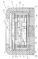
図1は、本願発明の一実施形態に係るマイクロホン装置を上向きに配置した状態で示す側断面図であり、図2は、これを分解して示す斜視図である。
【0023】
これらの図に示すように、本実施形態に係るマイクロホン装置10は、略円筒形の外周面形状を有するマイクロホン12と、このマイクロホン12を略円筒状に覆うようにして保持するゴム製のホルダ14とからなっている。
【0024】
まず、マイクロホン12の構成について説明する。
【0025】
マイクロホン12は、超小型のエレクトレットコンデンサマイクロホンであって、略円筒形のケース16内にマイクロホン本体18が収容されてなり、そのケース16の上面には、不織布等からなる円板状の音響フィルタ20が取り付けられている。
【0026】
マイクロホン本体18は、振動膜サブアッセンブリ24と、スペーサ26と、背極板28と、コイルスプリング30と、絶縁性ブッシュ32と、FET(電界効果トランジスタ)ボード34とからなっている。
【0027】
ケース16は、金属製(例えばアルミニウム製)であって、その外径は3mm程度、その高さは1.5mm程度に設定されている。このケース16は、その上端壁に放音孔16aが形成されており、また、その下端部16bにおいてFETボード34にカシメ固定されている。
【0028】
振動膜サブアッセンブリ24は、振動膜36が支持リング38に張設固定されてなっている。振動膜36は、円形の樹脂フィルムの上面に金属蒸着膜が形成されてなり、その外径はケース16の内径と略同一の値に設定されている。一方、支持リング38は、金属製であって、振動膜36と略同じ外径を有している。
【0029】
スペーサ26は、ケース16の内径と略同じ外径を有する金属製の薄板リングで構成されている。
【0030】
背極板28は、金属製の背極板本体28Aと、この背極板本体28Aの上面に熱融着されたエレクトレット28Bとからなり、該背極板28には複数の貫通孔28aが形成されている。エレクトレット28Bは、樹脂フィルムからなり、所定の表面電位(例えば−260V程度)が得られるよう分極処理が施されている。
【0031】
ケース16内においては、エレクトレット28Bと振動膜36とがスペーサ26を介して所定の微小間隔をおいて対向配置されており、これによりコンデンサ部を構成するようになっている。
【0032】
絶縁性ブッシュ32は、ケース16の内径と略同じ外径を有する円筒状部材であって、その内周側に背極板28およびコイルスプリング30が配置されるようになっている。その際、背極板28は、コイルスプリング30によりスペーサ26へ向けて弾性的に押圧されるようになっている。
【0033】
FETボード34は、ケース16の内径と略同じ外径を有するボード本体42と、このボード本体42の上面に実装されたFETチップ44およびコンデンサチップ46とからなっている。ボード本体42の上面には導電パターン42aが形成されており、ボード本体42の下面には、その中心部に円形の導電パターン42b、その外周縁部に環状の導電パターン42cが形成されている。導電パターン42cは、ケース16の下端部16bのカシメ固定代に沿って細幅で形成されている。
【0034】
FETチップ44は、そのゲート電極が導電パターン42aおよびコイルスプリング30を介して背極板28に電気的に接続されており、そのドレーン電極が導電パターン42aを介して導電パターン42bに電気的に接続されており、そのソース電極が導電パターン42a、42c、ケース16および支持リング38を介して振動膜36の金属蒸着膜に電気的に接続されている。
【0035】
そしてこれにより、本実施形態に係るマイクロホン12においては、そのケース16自体がアース端子を構成するとともに、そのFETボード34の導電パターン42bがプラス端子を構成するようになっている。
【0036】
次に、ホルダ14の構成について説明する。
【0037】
ホルダ14は、ケース16の外径と略同じ内径を有する円筒状の筒状部14Aと、この筒状部14Aの下端部からマイクロホン12の下端面へ回り込むようにして延長形成された略円板状の底壁部14Bと、筒状部14Aの上端部からマイクロホン12の上端面へ回り込むようにして環状に延長形成された環状リップ部14Cとからなっている。そして、このホルダ14に対してマイクロホン12を上方側から圧入することにより、マイクロホン装置10が構成されるようになっている。
【0038】
このホルダ14は、シリコーンゴムからなる絶縁性ゴムと、シリコーンゴムにフィラーとして金メッキが施された鉄粉を混入してなる導電性ゴムとが一体で形成されてなっている。
【0039】
具体的には、筒状部14Aおよび環状リップ部14Cは、絶縁性ゴムで構成されている。一方、底壁部14Bは、その外周縁部および中心部が導電性ゴムで構成されており、その中間に位置する環状部が絶縁性ゴムで構成されている。そして、この底壁部14Bの外周縁部が、ケース16の下端部16bに対して下方側から接触してマイクロホン12のアース端子と導通する第1導電部14aを構成しており、また、この底壁部14Bの中心部が、FETボード34の導電パターン42bに対して下方側から接触してマイクロホン12のプラス端子と導通する第2導電部14bを構成している。
【0040】
その際、第1導電部14aは、筒状部14Aの外周面の位置からその内周面よりも所定量内周側の位置までの範囲にわたって底壁部14Bの上面と面一で形成されている。一方、第2導電部14bは、その上面が底壁部14Bの他の部分に対して所定量上方へ突出するように形成されている。第2導電部14bをこのように形成することにより、FETボード34の導電パターン42bの位置がケース16の下端部16bの位置よりも幾分上方に変位しているにもかかわらず、第2導電部14bを導電パターン42bに対して確実に接触させるようになっている。
【0041】
図3は、本実施形態に係るマイクロホン装置10が搭載された携帯電話機100の要部を示す側断面図である。
【0042】
図示のように、携帯電話機100の上ケース102には、その所定位置に集音孔102aが形成されており、また、この上ケース102の内面には、集音孔102aを中心とする円筒状の環状リブ102bが形成されている。
【0043】
この上ケース102の下方には、外部基板(すなわち携帯電話機100の基板)104が設けられている。この外部基板104の上面には、円形の導電パターン104aと、この導電パターン104aを同心円状に囲む環状の導電パターン104bとが形成されている。これら各導電パターン104a、104bは、スルーホール104c、104dを介して外部基板104の下面に形成された導電パターン104e、104fに接続されている。
【0044】
そして、マイクロホン装置10は、そのホルダ14の上半部が上ケース102の環状リブ102b内の空間部に嵌め込まれた状態で、その底壁部14Bが外部基板104の上面に押し当てられることにより、携帯電話機100の所定位置に組み込まれるようになっている。その際、底壁部14Bは、その第1導電部14aが環状の導電パターン104bと接触するとともに、その第2導電部14bが円形の導電パターン104aと接触するようになっている。
【0045】
以上詳述したように、本実施形態に係るマイクロホン装置10は、そのマイクロホン12のケース16自体がアース端子として構成されるとともに、そのマイクロホン本体18の下端面中央にプラス端子としての導電パターン42bが形成されているので、マイクロホン12が超小型のマイクロホンであるにもかかわらず、その端子配置を、両端子間に十分な隙間が確保されたブルズアイ配置とすることができる。
【0046】
すなわち、本実施形態において、ボード本体42の下面外周縁部に形成された環状の導電パターン42cは、導電パターン42aおよびケース16と導通していれば足り、アース端子としての機能は不要であるので、これをケース16の下端部16bのカシメ固定代に沿って細幅で形成することができる。したがって、この導電パターン42cとボード本体42の中心部に形成された円形の導電パターン42bとの間に十分な隙間を確保することができる。
【0047】
なお、本実施形態のように導電パターン42cを介して導電パターン42aをケース16と導通させる代わりに、導電パターン42aを直接ケース16と導通させるように構成することも可能である。このようにした場合には、導電パターン42cが不要となるので、導電パターン42bとケース16の下端部16bとの間に一層大きな隙間を確保することが可能となる。
【0048】
また、本実施形態に係るマイクロホン装置10のホルダ14は、その下端部にマイクロホン12の下端面へ回り込む底壁部14Bが延長形成されており、この底壁部14Bは、その外周縁部がアース端子と導通する第1導電部14aとして導電性ゴムで構成されるとともに、その中心部がプラス端子と導通する第2導電部14bとして導電性ゴムで構成されているので、第1導電部14aと第2導電部14bとの間に十分な隙間を確保した上で、これら各導電部14a、14bと外部基板104の導通パターン104b、104aとの接触面積を十分に確保することができる。そしてこれにより、従来のようなリード線の使用を必要とすることなく、各導電部14a、14bを導通パターン104b、104aと確実に導通させることができる。
【0049】
このように本実施形態によれば、マイクロホン12が超小型であるにもかかわらず、その外部基板104への実装を容易かつ確実に行うことができる。
【0050】
特に本実施形態においては、第1導電部14aがケース16に対して下方側から接触するように構成されているので、絶縁性ゴムに比して高価な導電性ゴムの使用量を少なく抑えることができる。
【0051】
また、本実施形態に係るマイクロホン装置10においては、そのマイクロホン12のアース端子およびプラス端子のみならず、ホルダ14の第1および第2導電部14a、14bもブルズアイ配置となっており、しかもマイクロホン12のブルズアイ配置に対して一回り大きなブルズアイ配置となっているので、次のような作用効果を得ることができる。
【0052】
すなわち、外部基板104の導通パターンが、本実施形態のように同心円状に配置された導通パターン104a、104bとなっていない場合であっても、ブルズアイ配置を有するマイクロホンに対応した導通パターンであれば、これら導通パターンにホルダ14の第1および第2導電部14a、14bを確実に導通させることができる。
【0053】
しかも、ホルダ14の第1および第2導電部14a、14bは、マイクロホン12のブルズアイ配置に対して一回り大きなブルズアイ配置となっているので、超小型のマイクロホン12よりも一回り大きなマイクロホンに対応した導通パターンを有する一般的な外部基板に対して、該外部基板の構成を何ら変更することなく、マイクロホン装置10を実装することが可能となる。
【0054】
ところで、ホルダ14の第1導電部14aに関しては、これを上記実施形態のような構成とする代わりに、図4あるいは図5に示すような構成とすることも可能である。
【0055】
すなわち、図4に示す第1導電部14aは、ホルダ14の外周縁部において、その底壁部14Bの下面の位置から該底壁部14Bの上面よりも所定量上方の位置までの範囲にわたって筒状部14Aの内周面と面一で形成されている。そして、この第1導電部14aは、ケース16に対して外周側から接触するようになっている。このような構成を採用することにより、第1導電部14aと第2導電部14bとの間に一層大きな隙間を形成することができる。
【0056】
また、図5に示す第1導電部14aは、ホルダ14の外周縁部において、その筒状部14Aにおける底壁部14Bの上面よりも所定量上方の位置から底壁部14Bにおける筒状部14Aの内周面かよりも所定量内周側の位置までL字状の範囲にわたって形成されている。そして、この第1導電部14aは、ケース16に対して下方側および外周側から接触するようになっている。このような構成を採用することにより、第1導電部14aとマイクロホン12のアース端子との導通を一層確実に図ることができる。
【0057】
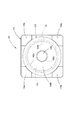
上記実施形態においては、第1導電部14aが底壁部14Bの外周縁部においてその全周にわたって形成されているものとして説明したが、図6(a)に底面図で示すように、第1導電部14aが底壁部14Bの外周縁部においてその周方向に所定間隔をおいて複数箇所に形成された構成、あるいは同図(b)に底面図で示すように、第1導電部14aが底壁部14Bの外周縁部の1箇所に形成された構成とすることも可能である。
【0058】
このような構成を採用した場合においても、マイクロホン12のアース端子を構成するケース16は環状に形成されているので、第1導電部14aとアース端子との導通を確実に図ることができる。また、上記実施形態のように、外部基板104の導通パターン104a、104bが同心円状に配置されている場合には、第1導電部14aと環状の導通パターン104bとの導通を確実に図ることができる。そして、このような構成を採用することにより、高価な導電性ゴムの使用量を一層少なく抑えることができる。
【0059】
また、上記実施形態においては、ホルダ14の筒状部14Aが円筒形の外周面形状を有するものとして説明したが、筒状部14Aの外周面形状をこれ以外の形状に設定することももちろん可能である。
【0060】
例えば、図7に底面図で示すように、筒状部14Aの外周面形状を略正方形に設定することが可能である。なお、同図に示すホルダ14は、その第1導電部14aが筒状部14Aの4箇所のコーナ部に各々形成された構成となっている。これら各第1導電部14aは、底壁部14Bの下面の位置から該底壁部14Bの上面よりも所定量上方の位置までの範囲にわたって筒状部14Aの内周面と面一で形成されており、マイクロホン12のケース16に対して外周側から接触するようになっている。
【0061】
上記実施形態においては、ホルダ14の第2導電部14bが、底壁部14Bの中心位置に円形で形成されているものとして説明したが、第1導電部14aから内周側に離れた位置で、かつマイクロホン12のプラス端子を構成する導電パターン42bとの導通を図り得る位置であれば、底壁部14Bの中心位置から多少ずれた位置に形成されたものとしてもよく、また、その形状や大きさ等についても任意に設定することが可能である。
【0062】
また、上記実施形態においては、ホルダ14を構成する絶縁性ゴムおよび導電性ゴムが、シリコーンゴムおよび金メッキが施された鉄粉をフィラーとしてシリコーンゴムに混入したもので構成されているものとして説明したが、これ以外の材質のものを用いることももちろん可能である。
【0063】
さらに、上記実施形態においては、マイクロホン12が略円筒形の外周面形状を有するものとして説明したが、略筒状の外周面形状であれば、これ以外の外周面形状(例えば断面が略矩形の外周面形状)を有するマイクロホンに、上記実施形態のホルダ14を適応させることも可能である。このようにした場合においても、上記実施形態と同様の作用効果を得ることが可能である。
【0064】
なお、上記実施形態においては、マイクロホン12がエレクトレットコンデンサマイクロホンであるものとして説明したが、これ以外の種類のマイクロホンである場合においても、上記実施形態と同様の端子構造を採用することにより、上記実施形態と同様の作用効果を得ることが可能である。
【図面の簡単な説明】
【図1】本願発明の一実施形態に係るマイクロホン装置を上向きに配置した状態で示す側断面図
【図2】上記マイクロホン装置を分解して示す斜視図
【図3】上記マイクロホン装置が搭載された携帯電話機の要部を示す側断面図
【図4】上記マイクロホン装置の第1の変形例を示す、図1と同様の図
【図5】上記マイクロホン装置の第2の変形例を示す、図1と同様の図
【図6】上記マイクロホン装置の第3および第4の変形例を示す底面図
【図7】上記マイクロホン装置の第5の変形例を示す底面図
【符号説明】
10 マイクロホン装置
12 マイクロホン
14 ホルダ
14A 筒状部
14B 底壁部
14C 環状リップ部
14a 第1導電部
14b 第2導電部
16 ケース
16a 放音孔
16b 下端部
18 マイクロホン本体
20 音響フィルタ
24 振動膜サブアッセンブリ
26 スペーサ
28 背極板
28A 背極板本体
28B エレクトレット
28a 貫通孔
30 コイルスプリング
32 絶縁性ブッシュ
34 FETボード
36 振動膜
38 支持リング
42 ボード本体
42a プラス端子としての導電パターン
42b、42c 導電パターン
44 FETチップ
46 コンデンサチップ
100 携帯電話機
102 上ケース
102a 集音孔
102b 環状リブ
104 外部基板
104a、104b、104e、104f 導電パターン
104c、104d スルーホール[0001]
TECHNICAL FIELD OF THE INVENTION
The present invention relates to a microphone device in which a microphone is held by a rubber holder, and also relates to the microphone and the holder.
[0002]
[Prior art]
Generally, a small microphone mounted on a mobile phone or the like has a substantially cylindrical outer peripheral surface shape as described in, for example, “Patent Document 1”, and a ground terminal and a positive terminal are provided on the lower end surface thereof. Is arranged. The ground terminal and the plus terminal allow conduction with a conductive pattern of a substrate (hereinafter, referred to as an “external substrate”) of a mobile phone or the like.
[0003]
At this time, the mounting of the microphone on the external substrate is performed so as to cover the microphone in a substantially cylindrical shape with a rubber holder as described in the above-mentioned “Patent Document 1” in order to prevent sound leakage and position. It is performed in a state where it is held.
[0004]
[Patent Document 1]
Japanese Patent No. 3244448 [Problems to be Solved by the Invention]
In recent years, microphones have been miniaturized, and those having a diameter of 3 mm or less have been developed. However, in such an ultra-small microphone, a ground terminal and a plus terminal are arranged on the lower end surface thereof. It is becoming difficult to secure space.
[0005]
In particular, in order to mount the microphone on the substrate without worrying about its directionality, it is preferable to employ a terminal arrangement called a bullseye (that is, a terminal arrangement in which the ground terminal and the positive terminal are concentric). However, if the outside diameter of the microphone becomes smaller than a certain degree, it will not be possible to secure a sufficient gap between both terminals, so when the microphone is attached to the external board, each terminal and the conductive pattern of the external board must be securely connected. However, there is a problem that it is difficult to conduct the current.
[0006]
For this reason, conventionally, in an ultra-small microphone, one end of a lead wire is soldered to each of a ground terminal and a plus terminal, and the other end of each lead wire is mounted when the microphone is mounted on an external board. Soldering to the conductive pattern on the external board is unavoidable, and there is a problem that the mounting workability is very poor.
[0007]
The present invention has been made in view of such circumstances, and even when a microphone is miniaturized, a microphone device that can be easily and reliably mounted on an external substrate, and the microphone and the holder. The purpose is to provide.
[0008]
[Means for Solving the Problems]
The present invention achieves the above object by devising a configuration of a ground terminal of a microphone and a configuration of a holder for holding the microphone.
[0009]
That is, the microphone device according to the present invention,
In a microphone device comprising: a microphone having a substantially cylindrical outer peripheral surface shape; and a rubber holder that holds the microphone so as to cover the microphone in a substantially cylindrical shape.
The microphone, the microphone body is housed in a substantially cylindrical metal case, the case itself is configured as a ground terminal, and a plus terminal is disposed on the lower end surface of the microphone body,
The holder includes a bottom wall extending from a lower end of the holder to a lower end surface of the microphone, and at least a part of an outer peripheral edge of the bottom wall is electrically connected to the ground terminal. The first conductive portion is made of conductive rubber, and a predetermined portion away from the first conductive portion to the inner peripheral side is made of conductive rubber as a second conductive portion that is electrically connected to the plus terminal. It is characterized by the following.
[0010]
Further, the microphone according to the present invention is
In a microphone having a substantially cylindrical outer peripheral surface shape,
The microphone body is housed in a substantially cylindrical metal case, the case itself is configured as a ground terminal, and a plus terminal is arranged on a lower end surface of the microphone body. It is.
[0011]
Further, the holder according to the present invention is:
In a rubber holder for holding a microphone having a substantially cylindrical outer peripheral surface shape so as to cover the microphone in a substantially cylindrical shape,
A bottom wall extending from the lower end of the holder to the lower end surface of the microphone; and at least a portion of an outer peripheral edge of the bottom wall and an inner peripheral side from the first conductive portion. The separated predetermined portion is made of conductive rubber.
[0012]
If the "bottom wall portion" is formed so as to extend from the lower end portion of the holder to the lower end surface of the microphone, it is not always necessary that the "bottom wall portion" is formed so as to completely close the lower end opening of the holder. Absent.
[0013]
The specific shape of the “holder” is not particularly limited as long as it is configured to cover the microphone in a substantially cylindrical shape. In this “holder”, the first and second conductive portions are made of conductive rubber. However, if electrical insulation between the first and second conductive portions is ensured, the first and second conductive portions of the holder may be removed. With respect to portions other than the first and second conductive portions, the entire region thereof may be formed of ordinary insulating rubber, or a portion formed of conductive rubber may be provided in a portion of the region.
[0014]
Effects of the Invention
As shown in the above configuration, the microphone device according to the present invention has a configuration including a microphone having a substantially cylindrical outer peripheral surface shape and a rubber holder that covers and holds the microphone in a substantially cylindrical shape. However, the microphone has a microphone body housed in a substantially cylindrical metal case, the case itself is configured as a ground terminal, and a plus terminal is arranged on the lower end surface of the microphone body. , The holder comprises a bottom wall extending from the lower end to the lower end surface of the microphone, and at least a part of the outer peripheral edge of the bottom wall is electrically connected to the ground terminal. A predetermined portion remote from the first conductive portion to the inner peripheral side is formed of conductive rubber as a second conductive portion that is electrically connected to the plus terminal. Runode, it is possible to obtain the following effects.
[0015]
That is, since the microphone case itself is configured as a ground terminal and the plus terminal is arranged on the lower end surface of the microphone body, even if the terminal arrangement is a bulls-eye arrangement in a very small microphone, the microphone terminal is connected between both terminals. A sufficient gap can be secured.
[0016]
The bottom wall portion of the holder is formed of conductive rubber as a first conductive portion at least part of an outer peripheral edge of which is electrically connected to a ground terminal, and has a predetermined distance away from the first conductive portion to an inner peripheral side. Since the portion is made of conductive rubber as the second conductive portion that is electrically connected to the positive terminal, a sufficient gap is secured between the first conductive portion and the second conductive portion, and each of these conductive portions is connected to the outside. A sufficient contact area with the conductive pattern of the substrate can be secured. Thus, each terminal of the microphone can be reliably connected to the conductive pattern of the external substrate without using a conventional lead wire.
[0017]
As described above, according to the present invention, even when the microphone is miniaturized, it can be easily and reliably mounted on the external substrate.
[0018]
In the above configuration, as described above, the specific shape of the holder is not particularly limited. However, if this is configured to have a substantially cylindrical outer peripheral surface shape, the first and second conductive portions of the holder can be bullseye. Accordingly, even when the conductive pattern of the external substrate is not a conductive pattern arranged concentrically, the conductive pattern can be formed in the conductive pattern and the first and second conductive portions. Can be reliably achieved.
[0019]
In the above configuration, the conduction between the first conductive portion of the holder and the ground terminal is performed by bringing the first conductive portion into contact with the case, but the manner of contact at that time is not particularly limited. The first conductive part is in contact with the case from below, the first conductive part is in contact with the case from the outer side, and the first conductive part is in contact with the case from the lower side and the outer side. It is possible to adopt a mode in which the operation is performed.
[0020]
In this case, if the mode in which the first conductive portion is brought into contact with the case from below is employed, the amount of the conductive rubber which is more expensive than the insulating rubber can be reduced. Further, by adopting a mode in which the first conductive portion is brought into contact with the case from the outer peripheral side, it is possible to easily form a larger gap between the first conductive portion and the second conductive portion. Further, by adopting a mode in which the first conductive portion is brought into contact with the case from the lower side and the outer peripheral side, conduction between the first conductive portion and the ground terminal can be more reliably achieved.
[0021]
BEST MODE FOR CARRYING OUT THE INVENTION
Hereinafter, embodiments of the present invention will be described with reference to the drawings.
[0022]
FIG. 1 is a side sectional view showing a microphone device according to an embodiment of the present invention arranged upward, and FIG. 2 is an exploded perspective view showing the microphone device.
[0023]
As shown in these figures, a
[0024]
First, the configuration of the
[0025]
The
[0026]
The microphone
[0027]
The
[0028]
The
[0029]
The
[0030]
The
[0031]
In the
[0032]
The insulating
[0033]
The
[0034]
The
[0035]
Thus, in the
[0036]
Next, the configuration of the
[0037]
The
[0038]
The
[0039]
Specifically, the
[0040]
At this time, the first
[0041]
FIG. 3 is a side sectional view showing a main part of a
[0042]
As shown, a
[0043]
An external board (that is, a board of the mobile phone 100) 104 is provided below the
[0044]
In the
[0045]
As described in detail above, in the
[0046]
That is, in the present embodiment, the annular
[0047]
Instead of conducting the
[0048]
The
[0049]
As described above, according to the present embodiment, the
[0050]
In particular, in the present embodiment, since the first
[0051]
In the
[0052]
That is, even if the conductive pattern of the
[0053]
In addition, the first and second
[0054]
By the way, the first
[0055]
That is, the first
[0056]
Further, the first
[0057]
In the above embodiment, the first
[0058]
Even when such a configuration is adopted, the
[0059]
In the above embodiment, the
[0060]
For example, as shown in a bottom view in FIG. 7, the outer peripheral shape of the
[0061]
In the above-described embodiment, the second
[0062]
In the above embodiment, the insulating rubber and the conductive rubber forming the
[0063]
Furthermore, in the above-described embodiment, the
[0064]
In the above embodiment, the
[Brief description of the drawings]
FIG. 1 is a side sectional view showing a microphone device according to an embodiment of the present invention in an upwardly arranged state. FIG. 2 is an exploded perspective view showing the microphone device. FIG. 3 is a perspective view showing the microphone device. FIG. 4 is a side sectional view showing a main part of a mobile phone. FIG. 4 is a view similar to FIG. 1 showing a first modification of the microphone device. FIG. 5 is a view showing a second modification of the microphone device. FIG. 6 is a bottom view showing third and fourth modifications of the microphone device. FIG. 7 is a bottom view showing a fifth modification of the microphone device.
Claims (6)
上記マイクロホンが、略筒状の金属製のケース内にマイクロホン本体が収容されてなり、上記ケース自体がアース端子として構成されるとともに上記マイクロホン本体の下端面にプラス端子が配置されており、
上記ホルダが、該ホルダの下端部から上記マイクロホンの下端面へ回り込むように延長形成された底壁部を備えてなり、この底壁部における外周縁部の少なくとも一部が上記アース端子と導通する第1導電部として導電性ゴムで構成されるとともに、該第1導電部から内周側に離れた所定部位が上記プラス端子と導通する第2導電部として導電性ゴムで構成されている、ことを特徴とするマイクロホン装置。In a microphone device comprising: a microphone having a substantially cylindrical outer peripheral surface shape; and a rubber holder that holds the microphone so as to cover the microphone in a substantially cylindrical shape.
The microphone, the microphone body is housed in a substantially cylindrical metal case, the case itself is configured as a ground terminal, and a plus terminal is disposed on the lower end surface of the microphone body,
The holder includes a bottom wall extending from a lower end of the holder to a lower end surface of the microphone, and at least a part of an outer peripheral edge of the bottom wall is electrically connected to the ground terminal. The first conductive portion is made of conductive rubber, and a predetermined portion away from the first conductive portion to the inner peripheral side is made of conductive rubber as a second conductive portion that is electrically connected to the plus terminal. A microphone device characterized by the above-mentioned.
略筒状の金属製のケース内にマイクロホン本体が収容されてなり、上記ケース自体がアース端子として構成されるとともに上記マイクロホン本体の下端面にプラス端子が配置されている、ことを特徴とするマイクロホン。In a microphone having a substantially cylindrical outer peripheral surface shape,
A microphone characterized in that the microphone body is housed in a substantially cylindrical metal case, the case itself is configured as a ground terminal, and a plus terminal is arranged on a lower end surface of the microphone body. .
該ホルダの下端部から上記マイクロホンの下端面へ回り込むように延長形成された底壁部を備えてなり、この底壁部における外周縁部の少なくとも一部および該第1導電部から内周側に離れた所定部位が導電性ゴムで構成されている、ことを特徴とするホルダ。In a rubber holder for holding a microphone having a substantially cylindrical outer peripheral surface shape so as to cover the microphone in a substantially cylindrical shape,
A bottom wall extending from the lower end of the holder to the lower end surface of the microphone; and at least a portion of an outer peripheral edge of the bottom wall and an inner peripheral side from the first conductive portion. A holder characterized in that a predetermined portion apart is made of conductive rubber.
Priority Applications (4)
| Application Number | Priority Date | Filing Date | Title |
|---|---|---|---|
| JP2002371543A JP4205420B2 (en) | 2002-12-24 | 2002-12-24 | Microphone device and holder |
| EP03258062A EP1434461A3 (en) | 2002-12-24 | 2003-12-19 | Microphone unit and holder used in the microphone unit |
| CNB2003101224020A CN100558190C (en) | 2002-12-24 | 2003-12-22 | Microphone arrangement |
| US10/743,020 US7054458B2 (en) | 2002-12-24 | 2003-12-23 | Holder used in the microphone unit |
Applications Claiming Priority (1)
| Application Number | Priority Date | Filing Date | Title |
|---|---|---|---|
| JP2002371543A JP4205420B2 (en) | 2002-12-24 | 2002-12-24 | Microphone device and holder |
Publications (2)
| Publication Number | Publication Date |
|---|---|
| JP2004207807A true JP2004207807A (en) | 2004-07-22 |
| JP4205420B2 JP4205420B2 (en) | 2009-01-07 |
Family
ID=32463499
Family Applications (1)
| Application Number | Title | Priority Date | Filing Date |
|---|---|---|---|
| JP2002371543A Expired - Fee Related JP4205420B2 (en) | 2002-12-24 | 2002-12-24 | Microphone device and holder |
Country Status (4)
| Country | Link |
|---|---|
| US (1) | US7054458B2 (en) |
| EP (1) | EP1434461A3 (en) |
| JP (1) | JP4205420B2 (en) |
| CN (1) | CN100558190C (en) |
Cited By (1)
| Publication number | Priority date | Publication date | Assignee | Title |
|---|---|---|---|---|
| US7797025B2 (en) | 2005-06-28 | 2010-09-14 | Research In Motion Limited | Microphone coupler for a communication device |
Families Citing this family (10)
| Publication number | Priority date | Publication date | Assignee | Title |
|---|---|---|---|---|
| US7787643B2 (en) * | 2004-11-24 | 2010-08-31 | Mwm Acoustics, Llc | System and method for RF immunity of electret condenser microphone |
| US20060245606A1 (en) * | 2005-04-27 | 2006-11-02 | Knowles Electronics, Llc | Electret condenser microphone and manufacturing method thereof |
| JP4761885B2 (en) * | 2005-08-18 | 2011-08-31 | ポリマテック株式会社 | Holder for small electronic components |
| DE602007005405D1 (en) * | 2006-01-26 | 2010-05-06 | Sonion Mems As | Elastomer shield for miniature microphones |
| US8213660B2 (en) * | 2006-04-07 | 2012-07-03 | Research In Motion Limited | Shielded microphone for mobile communications device |
| KR100758839B1 (en) * | 2006-05-22 | 2007-09-14 | 주식회사 비에스이 | Mounting method and holder for smd microphone |
| JP4740059B2 (en) * | 2006-07-27 | 2011-08-03 | スター精密株式会社 | Microphone housing and condenser microphone |
| JP4939922B2 (en) * | 2006-12-27 | 2012-05-30 | 株式会社オーディオテクニカ | Condenser microphone |
| CN101651913A (en) * | 2009-06-19 | 2010-02-17 | 瑞声声学科技(深圳)有限公司 | Microphone |
| CN110868680A (en) * | 2019-11-01 | 2020-03-06 | 钰太芯微电子科技(上海)有限公司 | Microphone structure with improved substrate |
Family Cites Families (6)
| Publication number | Priority date | Publication date | Assignee | Title |
|---|---|---|---|---|
| US4321432A (en) | 1978-12-23 | 1982-03-23 | Tokyo Shibaura Denki Kabushiki Kaisha | Electrostatic microphone |
| JPS622879Y2 (en) * | 1981-03-25 | 1987-01-22 | ||
| SE506093C2 (en) | 1994-04-05 | 1997-11-10 | Ericsson Ge Mobile Communicat | Elastomeric coupling |
| JP3244448B2 (en) | 1997-03-19 | 2002-01-07 | 富士高分子工業株式会社 | Small microphone assembly using conductive rubber contacts |
| EP0880299A1 (en) | 1997-05-23 | 1998-11-25 | Fuji Polymer Industries Co,, Ltd. | Miniature microphone arrangement |
| JP3283226B2 (en) * | 1997-12-26 | 2002-05-20 | ポリマテック株式会社 | How to make a holder |
-
2002
- 2002-12-24 JP JP2002371543A patent/JP4205420B2/en not_active Expired - Fee Related
-
2003
- 2003-12-19 EP EP03258062A patent/EP1434461A3/en not_active Withdrawn
- 2003-12-22 CN CNB2003101224020A patent/CN100558190C/en not_active Expired - Fee Related
- 2003-12-23 US US10/743,020 patent/US7054458B2/en not_active Expired - Fee Related
Cited By (1)
| Publication number | Priority date | Publication date | Assignee | Title |
|---|---|---|---|---|
| US7797025B2 (en) | 2005-06-28 | 2010-09-14 | Research In Motion Limited | Microphone coupler for a communication device |
Also Published As
| Publication number | Publication date |
|---|---|
| CN100558190C (en) | 2009-11-04 |
| US20040146171A1 (en) | 2004-07-29 |
| EP1434461A2 (en) | 2004-06-30 |
| EP1434461A3 (en) | 2006-01-11 |
| CN1510965A (en) | 2004-07-07 |
| US7054458B2 (en) | 2006-05-30 |
| JP4205420B2 (en) | 2009-01-07 |
Similar Documents
| Publication | Publication Date | Title |
|---|---|---|
| TWI376963B (en) | ||
| US8391515B2 (en) | Micro-speaker | |
| JP2007081614A (en) | Condenser microphone | |
| US20060115106A1 (en) | Condenser microphone unit | |
| JP4205420B2 (en) | Microphone device and holder | |
| JP3801985B2 (en) | Electret condenser microphone | |
| JP2001352597A (en) | Electro/acoustic converter having back terminal | |
| US20110158459A1 (en) | Loudspeaker and electronic device incorporating the same | |
| JP4198888B2 (en) | An apparatus comprising an electroacoustic transducer having terminal contacts extending in the transducer axial direction and a printed circuit board having mating contacts | |
| US6678383B2 (en) | Capacitor microphone | |
| JP3362640B2 (en) | Electret condenser microphone | |
| US20010031056A1 (en) | Electroacoustic transducer and structure for mounting an electroacoustic transducer | |
| JP2003163997A (en) | Capacitor microphone | |
| JP4040328B2 (en) | Electret condenser microphone | |
| JP4276108B2 (en) | Microphone unit mounting structure, electronic device including the same, and microphone unit mounting method | |
| JP2004032019A (en) | Capacitor microphone | |
| JP3609031B2 (en) | Condenser microphone | |
| JP4402470B2 (en) | Electroacoustic transducer | |
| JPH10145891A (en) | Electroacoustic transducer | |
| JP2007288669A (en) | Electret condenser microphone | |
| JP2007081844A (en) | Condenser microphone, mounting method of condenser microphone and portable terminal using the same | |
| JP2003102096A (en) | Electret condenser microphone | |
| CN109451410B (en) | Electret microphone and manufacturing method | |
| JP2003235099A (en) | Electrostatic microphone | |
| KR100526022B1 (en) | Condenser microphone |
Legal Events
| Date | Code | Title | Description |
|---|---|---|---|
| A621 | Written request for application examination |
Free format text: JAPANESE INTERMEDIATE CODE: A621 Effective date: 20051104 |
|
| A977 | Report on retrieval |
Free format text: JAPANESE INTERMEDIATE CODE: A971007 Effective date: 20071119 |
|
| A131 | Notification of reasons for refusal |
Free format text: JAPANESE INTERMEDIATE CODE: A131 Effective date: 20071127 |
|
| A521 | Request for written amendment filed |
Free format text: JAPANESE INTERMEDIATE CODE: A523 Effective date: 20080115 |
|
| A02 | Decision of refusal |
Free format text: JAPANESE INTERMEDIATE CODE: A02 Effective date: 20080507 |
|
| A521 | Request for written amendment filed |
Free format text: JAPANESE INTERMEDIATE CODE: A523 Effective date: 20080625 |
|
| A911 | Transfer to examiner for re-examination before appeal (zenchi) |
Free format text: JAPANESE INTERMEDIATE CODE: A911 Effective date: 20080717 |
|
| TRDD | Decision of grant or rejection written | ||
| A01 | Written decision to grant a patent or to grant a registration (utility model) |
Free format text: JAPANESE INTERMEDIATE CODE: A01 Effective date: 20081014 |
|
| A01 | Written decision to grant a patent or to grant a registration (utility model) |
Free format text: JAPANESE INTERMEDIATE CODE: A01 |
|
| A61 | First payment of annual fees (during grant procedure) |
Free format text: JAPANESE INTERMEDIATE CODE: A61 Effective date: 20081016 |
|
| FPAY | Renewal fee payment (event date is renewal date of database) |
Free format text: PAYMENT UNTIL: 20111024 Year of fee payment: 3 |
|
| R150 | Certificate of patent or registration of utility model |
Free format text: JAPANESE INTERMEDIATE CODE: R150 |
|
| LAPS | Cancellation because of no payment of annual fees |