JP2004205232A - Ultrasonic wave length measuring apparatus - Google Patents
Ultrasonic wave length measuring apparatus Download PDFInfo
- Publication number
- JP2004205232A JP2004205232A JP2002371318A JP2002371318A JP2004205232A JP 2004205232 A JP2004205232 A JP 2004205232A JP 2002371318 A JP2002371318 A JP 2002371318A JP 2002371318 A JP2002371318 A JP 2002371318A JP 2004205232 A JP2004205232 A JP 2004205232A
- Authority
- JP
- Japan
- Prior art keywords
- transmission
- probe
- measuring apparatus
- length measuring
- ultrasonic wave
- Prior art date
- Legal status (The legal status is an assumption and is not a legal conclusion. Google has not performed a legal analysis and makes no representation as to the accuracy of the status listed.)
- Granted
Links
Images


Abstract
Description
【0001】
【発明の属する技術分野】
本発明は、コンクリート、土中、などに埋設された、構造体の長さ計測に関するものである。
【0002】
【従来の技術】
トンネルの強度を増すために使用されるロックボルトはナトム工法としてよく利用されており、施工埋設後、その長さを確認することは管理上必要とされている。
また、過去相当時間経過した基礎コンクリート内の鋼材長さは資料が残っていないため、基礎を再利用するときに極めて有用である。
【0003】
金属物体の長さ計測において、弾性波又は超音波の端面からの反射時間を計測し、伝搬物質の音速から長さを求める手法は従来より良く知られている手法である。
【0004】
しかしながら、建築物の基礎に用いられた、鋼材などの長尺の物はその計測可能長さに限界があった。
【0005】
すなわち、金属探傷機に用いられる超音波パルス反射法を用いるか、又はインパクトハンマーを送信手段とし、AEセンサーを受信素子とする、弾性波の端面からの反射を用いる方法である。
【0006】
これらの手法は、一見合理的のように見えるが、測長という面からみると重大な欠陥がみられる。
【0007】
理由は、発生する弾性波の種類によって伝搬速度が異なるからである。
固体中の弾性波は、大きく分けて、縦波、横波、表面波、に分けられるが、伝搬媒質が同じであっても、波の速度が異なる。またこれらの波は同時に混在して発生するため、選択して利用する事は困難である。
【0008】
特に機械的打撃による弾性波は粒子速度が遅いため、周波数が低くなり、その大半は表面波として伝搬する。
このため、ムクの長尺金属端面からの反射は容易に得られるが、コンクリートで被覆拘束したり、土中に埋設すると、表面波の発生が阻害され、反射信号が極端に減少し計測不能に陥る。
この現象は、表面波が無くなり、縦波成分だけが金属中を伝搬したものをとらえるためである。
【0009】
金属探傷機は、釣鐘を撞木で打つがごとく、インパルス電圧を与えていた。あるいは、自由振動による共振回路を形成している。
インパルス電圧の時間幅をWとすれば、含まれる周波数成分の半値幅はT=1/Wとなり、振動子の帯域幅で決まる時間幅パルスが送出される。
【0010】
距離分解能を大きくするため広帯域の振動子が製作されるのが通例であり、振動子のQをできる限り、小さくする事が望まれ、計測媒体の弾性波減衰率と要求される距離分解能に応じて、周波数、すなわち発生する弾性波の波長を選んでいる。
【0011】
長尺の計測の場合は、媒質の減衰を小さくするため、周波数を下げる工夫がなされている。
【0012】
【発明が解決しようとする課題】
埋設後の、ロックボルト長が、設計仕様に定められた長さと、実際施工された長さに違いが生じており、社会資本の安全確保が求められている。
【0013】
また、資料の残っていない、古い埋設構造体の長さ計測は、基礎を再利用するという社会資本の有効活用のため、最近特に注目されている。
【0014】
長尺の鋼材などの測長可能長さは、送信エネルギーと、電気音響変換トランスジューサーの効率と受信増幅器の増幅率と信号対雑音比でよって決まってくるが、いずれの要素も限界があるため、充分ではなかった。
本考案により従来検出できなかった埋設、あるいは被覆された長尺の構造物長さを計測することが可能となる。
【0015】
【問題を解決するための手段】
探触子を共振させるため、バースト波により探触子を駆動した。
【0016】
探触子励振周波数をケーブルを含めた、反共振点に合わせた。
【0017】
探触子のQを20〜30に増加させた。
【0018】
送信エネルギーを有効に利用するため、送信時間中は受信回路を送信回路から切り離した。
【0019】
【発明の実施の形態】
本考案は、超音波パルス反射法を拘束された長尺金属の長さ計測に最適構成したものである。
【0020】
探触子の送受信効率を最大にするとともに、縦波を効果的に発生させ、拘束された、長尺金属構造体の長さを計測することを可能とした。
【0021】
【実施例】
以下、本発明の超音波測長装置の一実施例を図1〜図5を参照して説明する。
【0022】
バースト波の駆動波形は、パワーオペアンプなどによる線形電力増幅器を利用することが第一に考えられるが、電圧の高い高周波のバーストサイン波を得ることは容易ではない。
また駆動波形は振動の帯域幅で制限されるためサイン波である必要はなく、方形波で充分である。
このため、高出力を得るためのバースト波の駆動方法は、スイッチ素子による方形波の連続駆動が発熱が少なく小型軽量となり、経済性に優れるので、本実施例はこの方法によった。
【0023】
電気音響変換手段として用いられる探触子は、振動子素子として、圧電セラミックが通常用いられる。
【0024】
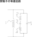
図3は圧電セラミックの等価回路である。
共振点とは、インピーダンスが最小となる周波数をいう、すなわち誘導成分L0、2とコンデンサー成分C0、3が直列共振を起こし、抵抗分R0、4だけになる点である。
反共振点とは、インピーダンスが最大となる周波数をいう、すなわちL0、2とCd、5の並列共振である。
【0025】
送信感度は共振点で、受信感度は反共振点で最大となる。従って送受2種の振動子を同軸構造に配置することも考えられるが、軸がずれるためと、各振動子の面積が半分減少するため総合感度は大きくならない。
【0026】
Cd、5は圧電セラミックの静電容量であって、実際エネルギーの送受信に寄与するのは動抵抗Rである。
【0027】
このため、L、1を並列に付加し、動作周波数での位相が出来るだけ小さく、ゼロに近くなるように工夫される。
【0028】
本考案では、送受総合感度が最大となるように、パルス反射法で用いられる振動子より逆にQを大きく作り、受信感度最大点である反共振点を動作点に設定して、数10サイクル以上のバースト波で励振をおこなう。
【0029】
このため、探触子に接続されるケーブルの静電容量も含めた周波数で共振状態となり、狭帯域で送受総合感度が著しく増大するのが本考案の特徴である。
【0030】
目的とする鋼材端からの位置検出確度を決定する反射信号時間幅は、送信バースト波のサイクル数に依存することになるが、検出感度と位置検出確度を勘案して、図1に示したゲインコントロールSTC回路で増減する。
【0031】
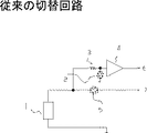
送受信切替回路について、説明する。
電圧微少であるときは、抵抗が大きくなる特徴のあるダイオードを組み合わせて、図4に示す従来例の構成でおこなわれるが、サイクルの長いバースト波の高電圧励振を反共振点で行うと、並列に加わる送受切換回路が負荷となり、送信エネルギーを消費する。このため、図5に示すように、送信時間中は、受信回路を切り離し、必要受信時間の時だけ接続される制御されたスイッチ素子8を設けた。
【0032】
図1は回路ブロック図である。
回路構成は従来のパルス反射法と基本的には類似しており、図1ゲイン信号には、図2のゲインモニタで示される信号波形が出力されるとともに、ゲインコントロールアンプで電圧に比例されたゲインが制御される。
【0033】
送信同期信号と同期してバースト送信信号が探触子に加えられ、増減制御されたDELAY時間後から時間とともに変化するゲイン制御信号が発生する。これは、STC回路としてよく知られた手法である。
【0034】
本考案の特徴は、送受信分離回路、送信バースト波発生回路、及び図2に示した送受信切替信号である。
【0035】
また、バンドパスフィルターは、送信信号の狭帯域特性に合致させるため、インパルス送信の場合より、狭帯域に設定されている。
【0036】
直径10〜25mm、長さ3〜6mのロックボルト場合、使用周波数は3〜5MHzが最適である。
【0037】
【発明の効果】
従来計測できなかった、周囲をコンクリートや、土砂などにより拘束された、長尺の金属長さを計測する事ができる。
【図面の簡単な説明】
【図1】本発明の超音波測長装置の一実施例を示すブロック図である。
【図2】信号の制御信号図である。
【図3】探触子の等価回路を示す図である。
【図4】従来の送受信切替回路を示す図である。
【図5】本実施例の送受信切替回路を示す図である。
【符号の説明】
図3
1 コイルL
2 誘導成分L0
3 コンデンサー成分CO
4 抵抗分R0
5 圧電セラミックの静電容量Cd
図4及び5
1 探触子
2 受信ダイオード
3 抵抗器
4 受信プリアンプ
5 送信ダイオード
6 受信信号
7 送信信号
8 電子スイッチ
9 送受信切替信号[0001]
TECHNICAL FIELD OF THE INVENTION
The present invention relates to measuring the length of a structure buried in concrete, soil, or the like.
[0002]
[Prior art]
Lock bolts used to increase the strength of tunnels are often used as the Natomo method, and it is necessary for management to check the length after construction and burial.
In addition, since there is no data on the length of steel in the foundation concrete after a considerable time in the past, it is extremely useful when reusing the foundation.
[0003]
In measuring the length of a metal object, a method of measuring the reflection time of an elastic wave or an ultrasonic wave from an end face and obtaining the length from the sound velocity of a propagating substance is a well-known method.
[0004]
However, long objects such as steel materials used for building foundations have a limited measurable length.
[0005]
That is, it is a method using an ultrasonic pulse reflection method used for a metal flaw detector, or a method using reflection from an end face of an elastic wave using an impact hammer as a transmitting means and an AE sensor as a receiving element.
[0006]
Although these methods seem reasonable at first glance, they have significant shortcomings in terms of length measurement.
[0007]
The reason is that the propagation speed differs depending on the type of generated elastic wave.
Elastic waves in solids can be broadly classified into longitudinal waves, transverse waves, and surface waves. Even if the propagation medium is the same, the speed of the waves is different. In addition, since these waves are generated simultaneously at the same time, it is difficult to select and use them.
[0008]
In particular, elastic waves due to mechanical impact have low particle velocities and therefore have low frequencies, and most of them propagate as surface waves.
For this reason, the reflection from the long metal end face of Muku can be easily obtained, but if it is covered with concrete or buried in the soil, the generation of surface waves will be hindered, the reflected signal will be extremely reduced and measurement will be impossible. Fall into.
This phenomenon is because the surface wave disappears, and only the longitudinal wave component catches the one that propagated in the metal.
[0009]
The metal flaw detector applied an impulse voltage, just like hitting a bell with a splinter. Alternatively, a resonance circuit by free vibration is formed.
Assuming that the time width of the impulse voltage is W, the half width of the included frequency component is T = 1 / W, and a time width pulse determined by the bandwidth of the vibrator is transmitted.
[0010]
In general, a wide-band vibrator is manufactured to increase the distance resolution, and it is desired to reduce the Q of the vibrator as much as possible. Depending on the elastic wave attenuation rate of the measurement medium and the required distance resolution, Thus, the frequency, that is, the wavelength of the generated elastic wave is selected.
[0011]
In the case of a long measurement, the frequency is reduced to reduce the attenuation of the medium.
[0012]
[Problems to be solved by the invention]
There is a difference between the length of the lock bolt after burial and the length stipulated in the design specifications and the actually constructed length, and it is required to ensure the safety of social capital.
[0013]
In addition, the measurement of the length of an old buried structure, for which no data remains, has attracted particular attention recently because of the effective use of social capital by reusing the foundation.
[0014]
The length that can be measured, such as a long steel material, is determined by the transmission energy, the efficiency of the electroacoustic transducer, the amplification factor of the receiving amplifier, and the signal-to-noise ratio. Was not enough.
According to the present invention, it is possible to measure the length of a long buried or covered long structure that could not be detected conventionally.
[0015]
[Means to solve the problem]
The probe was driven by a burst wave to resonate the probe.
[0016]
The probe excitation frequency was adjusted to the anti-resonance point including the cable.
[0017]
The Q of the probe was increased to 20-30.
[0018]
In order to make effective use of the transmission energy, the receiving circuit was disconnected from the transmitting circuit during the transmission time.
[0019]
BEST MODE FOR CARRYING OUT THE INVENTION
In the present invention, the ultrasonic pulse reflection method is optimally configured for measuring the length of a long metal constrained.
[0020]
While maximizing the transmission and reception efficiency of the probe, it was possible to effectively generate longitudinal waves and to measure the length of a constrained long metal structure.
[0021]
【Example】
Hereinafter, an embodiment of an ultrasonic length measuring apparatus according to the present invention will be described with reference to FIGS.
[0022]
As the driving waveform of the burst wave, it is first conceivable to use a linear power amplifier such as a power operational amplifier, but it is not easy to obtain a high-frequency, high-frequency burst sine wave.
Further, since the driving waveform is limited by the bandwidth of the vibration, it does not need to be a sine wave, and a square wave is sufficient.
For this reason, the method of driving a burst wave to obtain a high output is based on this method, since continuous driving of a square wave by a switch element generates little heat, is small and lightweight, and is economical.
[0023]
In a probe used as the electroacoustic conversion means, a piezoelectric ceramic is usually used as a transducer element.
[0024]
FIG. 3 is an equivalent circuit of the piezoelectric ceramic.
The resonance point refers to a frequency at which the impedance becomes minimum, that is, a point at which the induction components L0 and L2 and the capacitor components C0 and C3 cause series resonance, and only the resistance components R0 and R4 are obtained.
The anti-resonance point refers to the frequency at which the impedance becomes maximum, that is, the parallel resonance of L0, 2 and Cd, 5.
[0025]
The transmission sensitivity is at the resonance point, and the reception sensitivity is at the anti-resonance point. Therefore, it is conceivable to arrange two types of transducers in a coaxial structure. However, since the axes are shifted and the area of each transducer is reduced by half, the overall sensitivity does not increase.
[0026]
Cd and 5 are the capacitances of the piezoelectric ceramic, and the dynamic resistance R contributes to the actual transmission and reception of energy.
[0027]
Therefore, L and 1 are added in parallel so that the phase at the operating frequency is as small as possible and close to zero.
[0028]
In the present invention, the Q is made larger than the oscillator used in the pulse reflection method so that the total transmission and reception sensitivity is maximized, and the anti-resonance point which is the maximum point of the reception sensitivity is set as the operating point, and several tens of cycles Excitation is performed with the above burst waves.
[0029]
For this reason, it is a characteristic of the present invention that the resonance state occurs at the frequency including the capacitance of the cable connected to the probe, and the overall transmission / reception sensitivity is significantly increased in a narrow band.
[0030]
The reflected signal time width that determines the accuracy of position detection from the target steel material end depends on the number of cycles of the transmission burst wave. However, in consideration of the detection sensitivity and the position detection accuracy, the gain shown in FIG. It is increased or decreased by the control STC circuit.
[0031]
The transmission / reception switching circuit will be described.
When the voltage is very low, a diode having a characteristic of increasing the resistance is combined and the conventional configuration shown in FIG. 4 is used. However, when high voltage excitation of a long cycle burst wave is performed at an anti-resonance point, The transmission / reception switching circuit acting as a load becomes a load and consumes transmission energy. For this reason, as shown in FIG. 5, the receiving circuit is disconnected during the transmission time, and the controlled switch element 8 connected only during the required reception time is provided.
[0032]
FIG. 1 is a circuit block diagram.
The circuit configuration is basically similar to the conventional pulse reflection method. The signal waveform shown by the gain monitor in FIG. 2 is output as the gain signal in FIG. 1 and the gain control amplifier is proportional to the voltage. The gain is controlled.
[0033]
A burst transmission signal is applied to the probe in synchronization with the transmission synchronization signal, and a gain control signal that changes with time is generated after a delay time that has been controlled to increase or decrease. This is a technique well known as an STC circuit.
[0034]
The features of the present invention are a transmission / reception separation circuit, a transmission burst wave generation circuit, and a transmission / reception switching signal shown in FIG.
[0035]
Further, the bandpass filter is set to have a narrower band than in the case of impulse transmission in order to match the narrowband characteristic of the transmission signal.
[0036]
In the case of a lock bolt having a diameter of 10 to 25 mm and a length of 3 to 6 m, the use frequency is optimally 3 to 5 MHz.
[0037]
【The invention's effect】
It is possible to measure long metal lengths whose surroundings were constrained by concrete, earth and sand, which could not be measured conventionally.
[Brief description of the drawings]
FIG. 1 is a block diagram showing an embodiment of an ultrasonic length measuring apparatus according to the present invention.
FIG. 2 is a control signal diagram of signals.
FIG. 3 is a diagram showing an equivalent circuit of a probe.
FIG. 4 is a diagram showing a conventional transmission / reception switching circuit.
FIG. 5 is a diagram illustrating a transmission / reception switching circuit according to the embodiment;
[Explanation of symbols]
FIG.
1 coil L
2 Induction component L0
3 Condenser component CO
4 Resistance R0
5. Capacitance Cd of piezoelectric ceramic
Figures 4 and 5
REFERENCE SIGNS LIST 1 probe 2
Claims (2)
駆動周波数を電気音響変換手段の反共振点で行うことを特徴とする測長装置。Having electro-acoustic conversion means and burst wave driving means,
A length measuring device wherein the driving frequency is measured at an anti-resonance point of the electroacoustic conversion means.
Priority Applications (1)
| Application Number | Priority Date | Filing Date | Title |
|---|---|---|---|
| JP2002371318A JP4319402B2 (en) | 2002-12-24 | 2002-12-24 | Ultrasonic measuring device |
Applications Claiming Priority (1)
| Application Number | Priority Date | Filing Date | Title |
|---|---|---|---|
| JP2002371318A JP4319402B2 (en) | 2002-12-24 | 2002-12-24 | Ultrasonic measuring device |
Publications (2)
| Publication Number | Publication Date |
|---|---|
| JP2004205232A true JP2004205232A (en) | 2004-07-22 |
| JP4319402B2 JP4319402B2 (en) | 2009-08-26 |
Family
ID=32810227
Family Applications (1)
| Application Number | Title | Priority Date | Filing Date |
|---|---|---|---|
| JP2002371318A Expired - Lifetime JP4319402B2 (en) | 2002-12-24 | 2002-12-24 | Ultrasonic measuring device |
Country Status (1)
| Country | Link |
|---|---|
| JP (1) | JP4319402B2 (en) |
Cited By (4)
| Publication number | Priority date | Publication date | Assignee | Title |
|---|---|---|---|---|
| CN100374819C (en) * | 2006-04-29 | 2008-03-12 | 北京工业大学 | Method of nondestructive detecting anchor arm length buried in defferent mediums by utilizing supersonic guided wave |
| JP2008268116A (en) * | 2007-04-24 | 2008-11-06 | Tsutsui Denshi:Kk | Buried object soundness assorting device |
| CN101458232B (en) * | 2009-01-09 | 2011-01-12 | 北京理工大学 | Anchor rod anchoring quality detecting instrument |
| KR102184988B1 (en) * | 2020-10-14 | 2020-12-01 | 한국건설기술연구원 | Measuring Apparatus and Measuring Method of Embedment Depth of Embedded Anchor Using Ultrasonic Wave |
Citations (13)
| Publication number | Priority date | Publication date | Assignee | Title |
|---|---|---|---|---|
| JPS5288057A (en) * | 1976-01-16 | 1977-07-22 | Omron Tateisi Electronics Co | Object detector |
| JPS55122174A (en) * | 1979-03-14 | 1980-09-19 | Secom Co Ltd | Ultrasonic oscillator and ultrasonic sensor |
| JPS57131085A (en) * | 1981-02-05 | 1982-08-13 | Yokogawa Hokushin Electric Corp | Ultrasonic wave measuring system |
| JPS57204479A (en) * | 1981-06-12 | 1982-12-15 | Fujitsu Ltd | Ultrasonic transmitting and receiving device |
| JPS5881470A (en) * | 1981-11-10 | 1983-05-16 | 東北金属工業株式会社 | Oscillator circuit for ultrasonic processing machine |
| JPS60140168A (en) * | 1983-12-27 | 1985-07-25 | Matsushita Electric Ind Co Ltd | Ultrasonic distance measuring apparatus |
| JPH02163687A (en) * | 1988-12-19 | 1990-06-22 | Hitachi Ltd | Range finding method |
| JPH08254454A (en) * | 1995-03-15 | 1996-10-01 | Sanyo Electric Co Ltd | Ultrasonic sensor and dispensing device using it |
| JPH08327732A (en) * | 1995-05-30 | 1996-12-13 | Kasuga Denki Kk | Ultrasonic wave level sensor |
| JPH09166659A (en) * | 1995-12-15 | 1997-06-24 | Tokin Corp | Aerial ultrasonic transmitter, aerial ultrasonic receiver, and aerial ultrasonic transmitter/receiver equipped therewith |
| JPH11103496A (en) * | 1997-09-29 | 1999-04-13 | Sony Corp | Ultrasonic sensor |
| JPH11153665A (en) * | 1997-11-21 | 1999-06-08 | Sony Corp | Ultrasonic sensor |
| JP2001027520A (en) * | 1999-07-14 | 2001-01-30 | Yakichi Higo | Measuring method for rock anchor length |
-
2002
- 2002-12-24 JP JP2002371318A patent/JP4319402B2/en not_active Expired - Lifetime
Patent Citations (13)
| Publication number | Priority date | Publication date | Assignee | Title |
|---|---|---|---|---|
| JPS5288057A (en) * | 1976-01-16 | 1977-07-22 | Omron Tateisi Electronics Co | Object detector |
| JPS55122174A (en) * | 1979-03-14 | 1980-09-19 | Secom Co Ltd | Ultrasonic oscillator and ultrasonic sensor |
| JPS57131085A (en) * | 1981-02-05 | 1982-08-13 | Yokogawa Hokushin Electric Corp | Ultrasonic wave measuring system |
| JPS57204479A (en) * | 1981-06-12 | 1982-12-15 | Fujitsu Ltd | Ultrasonic transmitting and receiving device |
| JPS5881470A (en) * | 1981-11-10 | 1983-05-16 | 東北金属工業株式会社 | Oscillator circuit for ultrasonic processing machine |
| JPS60140168A (en) * | 1983-12-27 | 1985-07-25 | Matsushita Electric Ind Co Ltd | Ultrasonic distance measuring apparatus |
| JPH02163687A (en) * | 1988-12-19 | 1990-06-22 | Hitachi Ltd | Range finding method |
| JPH08254454A (en) * | 1995-03-15 | 1996-10-01 | Sanyo Electric Co Ltd | Ultrasonic sensor and dispensing device using it |
| JPH08327732A (en) * | 1995-05-30 | 1996-12-13 | Kasuga Denki Kk | Ultrasonic wave level sensor |
| JPH09166659A (en) * | 1995-12-15 | 1997-06-24 | Tokin Corp | Aerial ultrasonic transmitter, aerial ultrasonic receiver, and aerial ultrasonic transmitter/receiver equipped therewith |
| JPH11103496A (en) * | 1997-09-29 | 1999-04-13 | Sony Corp | Ultrasonic sensor |
| JPH11153665A (en) * | 1997-11-21 | 1999-06-08 | Sony Corp | Ultrasonic sensor |
| JP2001027520A (en) * | 1999-07-14 | 2001-01-30 | Yakichi Higo | Measuring method for rock anchor length |
Cited By (4)
| Publication number | Priority date | Publication date | Assignee | Title |
|---|---|---|---|---|
| CN100374819C (en) * | 2006-04-29 | 2008-03-12 | 北京工业大学 | Method of nondestructive detecting anchor arm length buried in defferent mediums by utilizing supersonic guided wave |
| JP2008268116A (en) * | 2007-04-24 | 2008-11-06 | Tsutsui Denshi:Kk | Buried object soundness assorting device |
| CN101458232B (en) * | 2009-01-09 | 2011-01-12 | 北京理工大学 | Anchor rod anchoring quality detecting instrument |
| KR102184988B1 (en) * | 2020-10-14 | 2020-12-01 | 한국건설기술연구원 | Measuring Apparatus and Measuring Method of Embedment Depth of Embedded Anchor Using Ultrasonic Wave |
Also Published As
| Publication number | Publication date |
|---|---|
| JP4319402B2 (en) | 2009-08-26 |
Similar Documents
| Publication | Publication Date | Title |
|---|---|---|
| Perez et al. | Acoustic emission detection using fiber Bragg gratings | |
| Gan et al. | The use of broadband acoustic transducers and pulse-compression techniques for air-coupled ultrasonic imaging | |
| CN102507655A (en) | Method for monitoring compaction of concrete-filled steel tube structure based on piezoelectric intelligent aggregate | |
| CN108594238B (en) | Transient signal-based device and method for calibrating electroacoustic performance of underwater acoustic transducer | |
| JPH0525045B2 (en) | ||
| Zhu et al. | Non-contact detection of surface waves in concrete using an air-coupled sensor | |
| Lee et al. | Evaluation of rock bolt integrity using Fourier and wavelet transforms | |
| CN102364336A (en) | Ultrasonic wave sensor for pile supersonic wave detection | |
| EP2574915A2 (en) | Devices, systems and methods of detecting defects in workpieces | |
| JPH07218477A (en) | Searching device | |
| WO2000013008A1 (en) | Apparatus for nondestructive testing | |
| Stepinski | Novel instrument for inspecting rock bolt integrity using ultrasonic guided waves | |
| CN109115878A (en) | A kind of bridge prestress pore channel mud jacking compactness supersonic detection device and its detection method | |
| CN202075264U (en) | Ultrasonic sensor for ultrasonic pile foundation detection | |
| JP4795925B2 (en) | Ultrasonic thickness measurement method and apparatus | |
| JP4319402B2 (en) | Ultrasonic measuring device | |
| CN1172196C (en) | Acoustic resonance method of measuring sand flow cavity volume | |
| Filipiak et al. | Surface acoustic waves for the detection of small vibrations | |
| Da Cunha et al. | Improved longitudinal EMAT transducer for elastic constant extraction | |
| CN219641637U (en) | Ultrasonic guided wave detection device for oil and gas pipeline | |
| Donskoy et al. | Nonlinear seismo-acoustic land mine detection: Field test | |
| JP2006078243A (en) | Nondestructive geometry diagnosing method for buried object and its device | |
| Puckett et al. | A time-reversal mirror in a solid circular waveguide using a single, time-reversal element | |
| CN109297580A (en) | A kind of device and method measuring ultrasonic velocity | |
| WO2020191804A1 (en) | High-precision long-distance underwater acoustic ranging method based on low-frequency continuous sound wave peak capture |
Legal Events
| Date | Code | Title | Description |
|---|---|---|---|
| A621 | Written request for application examination |
Free format text: JAPANESE INTERMEDIATE CODE: A621 Effective date: 20051219 |
|
| A977 | Report on retrieval |
Free format text: JAPANESE INTERMEDIATE CODE: A971007 Effective date: 20080131 |
|
| A131 | Notification of reasons for refusal |
Free format text: JAPANESE INTERMEDIATE CODE: A131 Effective date: 20080318 |
|
| A521 | Request for written amendment filed |
Free format text: JAPANESE INTERMEDIATE CODE: A523 Effective date: 20080508 |
|
| A131 | Notification of reasons for refusal |
Free format text: JAPANESE INTERMEDIATE CODE: A131 Effective date: 20080701 |
|
| A521 | Request for written amendment filed |
Free format text: JAPANESE INTERMEDIATE CODE: A523 Effective date: 20080829 |
|
| A521 | Request for written amendment filed |
Free format text: JAPANESE INTERMEDIATE CODE: A523 Effective date: 20081024 |
|
| A131 | Notification of reasons for refusal |
Free format text: JAPANESE INTERMEDIATE CODE: A131 Effective date: 20090223 |
|
| A521 | Request for written amendment filed |
Free format text: JAPANESE INTERMEDIATE CODE: A523 Effective date: 20090306 |
|
| TRDD | Decision of grant or rejection written | ||
| A01 | Written decision to grant a patent or to grant a registration (utility model) |
Free format text: JAPANESE INTERMEDIATE CODE: A01 Effective date: 20090526 |
|
| A01 | Written decision to grant a patent or to grant a registration (utility model) |
Free format text: JAPANESE INTERMEDIATE CODE: A01 |
|
| A61 | First payment of annual fees (during grant procedure) |
Free format text: JAPANESE INTERMEDIATE CODE: A61 Effective date: 20090528 |
|
| FPAY | Renewal fee payment (event date is renewal date of database) |
Free format text: PAYMENT UNTIL: 20120605 Year of fee payment: 3 |
|
| R150 | Certificate of patent or registration of utility model |
Ref document number: 4319402 Country of ref document: JP Free format text: JAPANESE INTERMEDIATE CODE: R150 |
|
| FPAY | Renewal fee payment (event date is renewal date of database) |
Free format text: PAYMENT UNTIL: 20120605 Year of fee payment: 3 |
|
| FPAY | Renewal fee payment (event date is renewal date of database) |
Free format text: PAYMENT UNTIL: 20150605 Year of fee payment: 6 |
|
| R250 | Receipt of annual fees |
Free format text: JAPANESE INTERMEDIATE CODE: R250 |
|
| S531 | Written request for registration of change of domicile |
Free format text: JAPANESE INTERMEDIATE CODE: R313532 |
|
| R350 | Written notification of registration of transfer |
Free format text: JAPANESE INTERMEDIATE CODE: R350 |
|
| R250 | Receipt of annual fees |
Free format text: JAPANESE INTERMEDIATE CODE: R250 |
|
| R255 | Notification that request for automated payment was rejected |
Free format text: JAPANESE INTERMEDIATE CODE: R2525 |
|
| R250 | Receipt of annual fees |
Free format text: JAPANESE INTERMEDIATE CODE: R250 |
|
| R250 | Receipt of annual fees |
Free format text: JAPANESE INTERMEDIATE CODE: R250 |
|
| R255 | Notification that request for automated payment was rejected |
Free format text: JAPANESE INTERMEDIATE CODE: R2525 |
|
| R250 | Receipt of annual fees |
Free format text: JAPANESE INTERMEDIATE CODE: R250 |
|
| EXPY | Cancellation because of completion of term |