JP2004204502A - Mounting structure of roof functional panel - Google Patents

Mounting structure of roof functional panel Download PDF

Info

Publication number
JP2004204502A
JP2004204502A JP2002373196A JP2002373196A JP2004204502A JP 2004204502 A JP2004204502 A JP 2004204502A JP 2002373196 A JP2002373196 A JP 2002373196A JP 2002373196 A JP2002373196 A JP 2002373196A JP 2004204502 A JP2004204502 A JP 2004204502A
Authority
JP
Japan
Prior art keywords
base plate
roof
base
corrugated
functional panel
Prior art date
Legal status (The legal status is an assumption and is not a legal conclusion. Google has not performed a legal analysis and makes no representation as to the accuracy of the status listed.)
Granted
Application number
JP2002373196A
Other languages
Japanese (ja)
Other versions
JP3829799B2 (en
Inventor
Masatoshi Sekoguchi
雅利 世古口
Tomohide Yoshida
朋秀 吉田
Current Assignee (The listed assignees may be inaccurate. Google has not performed a legal analysis and makes no representation or warranty as to the accuracy of the list.)
Panasonic Electric Works Co Ltd
Original Assignee
Matsushita Electric Works Ltd
Priority date (The priority date is an assumption and is not a legal conclusion. Google has not performed a legal analysis and makes no representation as to the accuracy of the date listed.)
Filing date
Publication date
Application filed by Matsushita Electric Works Ltd filed Critical Matsushita Electric Works Ltd
Priority to JP2002373196A priority Critical patent/JP3829799B2/en
Publication of JP2004204502A publication Critical patent/JP2004204502A/en
Application granted granted Critical
Publication of JP3829799B2 publication Critical patent/JP3829799B2/en
Anticipated expiration legal-status Critical
Expired - Fee Related legal-status Critical Current

Links

Images

Abstract

<P>PROBLEM TO BE SOLVED: To stably support a roof functional panel by a base plate of high rigidity while improving drainage from between the base plate and a roof surface, to easily connect a plurality of base plates and to mount the roof functional panel so that water does not infiltrate into a roof backing. <P>SOLUTION: The metal base plate 1 of a corrugated plate shape with crests 15 and trough parts 16 alternately formed in a lateral direction is placed on roofing tiles 6. Metal fixing frames 17 are placed on the crests 15 of the base plate 1 to extend in the lateral direction of the base plate 1. Fasteners 18 are driven into the roof backing 13 from the fixing frames 17 through the crests 15 of the base plate 1 and the roofing tiles 6 to fix the fixing frames 17 and the base plate 1. The roof functional panel A such as a solar battery panel 8, a solar heat collecting panel or a seeding and planting panel is placed on the base plate 1 by the fixing frames 17. Peripheral edges of the roof functional panel A are fitted by fittings 3 fixed to the base plate 1. <P>COPYRIGHT: (C)2004,JPO&NCIPI

Description

【0001】
【発明の属する技術分野】
本発明は、屋根の屋根瓦の上に太陽電池パネル、太陽熱集熱パネル、緑化パネル等の屋根機能パネルを取り付ける構造に関するものである。
【0002】
【従来の技術】
従来、太陽電池パネルを屋根の屋根瓦の上に設置する一例としては、例えば、図15に示すものがある。金属にて矩形状に形成せる平板状のベース板1′の四隅に図15(a)に示すように取り付け孔2を穿孔し、この取り付け孔2に取り付け金具3をビスにて図15(b)に示すように取着する。次いでこのベース板1′を平板瓦のような屋根瓦を葺いた屋根面上に載せ、ベース板1′に予め設けたスリット状の固定孔から釘、ビス等の固着具4を屋根下地まで打入して固定する。この際、屋根面上に複数枚のベース板1′が並べて敷設されるが、屋根面の軒棟方向に隣り合うベース板1′は重ね合わせで止水され、左右に隣り合うベース板1′間はジョイナーまたは捨て板金等を用いて止水される。固着具4を打入した部分はカバー材5で図15(c)に示すように覆われる。ベース板1′の棟側の端部とこれより棟側の屋根瓦6との間は水切り板7で止水される。このようにベース板1′を屋根面上に取り付けた状態で各ベース板1′の上には夫々太陽電池パネル8が配置され、ベース板1′に夫々太陽電池パネル8が取り付けられる。
【0003】
また従来、太陽電池パネルを屋根の屋根瓦上に設置する他の例としては、図16に示すものがある(例えば、特許文献1参照)。これは矩形状の枠組したフレーム部材9に太陽電池パネル8を嵌め込んで装着してあり、フレーム部材9の四隅に下方に突出する脚部10を設けてあり、脚部10の部分では上面から脚部10の下端まで至るように取り付け孔11を穿孔してある。そして脚部10の下端を屋根面に載置することでフレーム部材9を屋根面上に設置し、取り付け孔11から固定ねじ12を挿通して屋根瓦6の下の屋根下地13まて固定ねじ12を螺合してフレーム部材9を固定している。
【0004】
【特許文献1】
特開平11−131734号公報
【0005】
【発明が解決しようとする課題】
上記の図15に示す従来例の場合、平板瓦のような屋根瓦6を葺くことにより軒棟方向に隣り合う屋根瓦6間に屋根瓦6の厚み分の段差がある屋根面上にベース板1′を載設するためにベース板1にはある程度の剛性が必要であるが、上記従来例のベース板1は単なる平板状であるために剛性があまりない。平板状のベース板1′に剛性を持たせるには板厚を増加させるなどしなければならないが、板厚を増加させると、部材のコストを増したり重量を増したりするという問題がある。また平板状のベース板1′を屋根面に設置した場合、ベース板1′と屋根面との間の水はけが悪く、汚れ、腐食の原因となるという問題がある。また平板状のベース板1′では左右に隣り合うベース板1′間の止水をする構造が複雑になるという問題がある(平板間はジョイナーまたは捨て板金などを用いて止水を確保する必要がある)。
【0006】
また上記の図16に示す従来例の場合、脚部10でフレーム部材9が屋根面より上に浮くように取り付けられるために太陽電池パネル8やフレーム部材9との間に隙間ができて水はけがよいが、脚部10でフレーム部材9全体を浮かせて支持する構造のためにフレーム部材9には剛性を要し、フレーム部材9の重量が重くなるという問題ある。また取り付け孔11から挿通した固定ねじ12を屋根瓦6を介して屋根下地13まで螺合しているが、このようにして固定した場合、フレーム部材9の上から取り付け孔11や固定ねじ12を介して屋根下地13まで雨水が浸入し、屋根下地を腐らせるおそれがある。
【0007】
本発明は上記の点に鑑みてなされたものであり、剛性の高いベース板にて安定よく支持でき、しかもベース板と屋根面との間からの水はけをよくでき、さらに複数のベース板の接続を容易にでき、さらに屋根下地に水が浸入しないうように取り付けることができる屋根機能パネルの取り付け構造を提供することを課題とするものである。
【0008】
【課題を解決するための手段】
上記課題を解決するための本発明の屋根機能パネルの取り付け構造は、左右方向に山部15と谷部16とを交互に設けた金属の波板状のベース板1を屋根瓦6の上に載設し、山部15や谷部16の長手方向と直交する方向に長手方向が向く金属の固定フレーム17をベース板1の山部15上にベース板1の左右方向に亙るように載置し、固定フレーム17からビス、釘等の固着具18をベース板1の山部、屋根瓦6を介して屋根下地13まで打設して固定フレーム17とベース板1とを固定し、固定フレーム17を介してベース板1上に太陽電池パネル8、太陽熱集熱パネル、緑化パネル26等の屋根機能パネルAを載置し、ベース板1に固定した取り付け金具3で屋根機能パネルAの周縁を固定したことを特徴とする。上記のように山部15と谷部16を交互に設けた金属の波板状のベース板1を用いていることにより板厚を厚くしたりすることなくベース板1の剛性を上げることができ、コストを削減しながら必要な強度が得られると共に、ベース板1の重量を軽減できて施工性が向上できる。ベース板1は波板状であるためにベース板1と屋根面との水はけがよくてベース板1と屋根面との間に水が溜まらず汚れや腐食の問題を発生しないようにできる。固定フレーム17からビス、釘等の固着具18をベース板1の山部15、屋根瓦6を介して屋根下地13に打設してベース板1を固定するために固着具18を打入する部分から屋根下地13に雨水が浸入するおそれがないものであり、しかも固定フレーム17上に載設した屋根機能パネルAはベース板1に固定した取り付け金具3で取り付けるために屋根機能パネルAを固定する部分から雨水が一切浸入するおそれのないものであり、屋根下地13や小屋裏に雨水が浸入して腐食したりするおそれがない。
【0009】
また波板状のベース板1を左右に複数枚並べ、左右に隣り合うベース板1間で左右のベース板1の波板形状を互い重ね合わせて接続したことを特徴とすることも好ましい。このように左右に隣り合うベース板1の左右の端部を重ね合わせることにより防水的に接続できる。
【0010】
また波板状のベース板1を軒棟方向に複数枚並べ、軒棟方向に隣り合うベース板1間で両ベース板1の波板形状を互いに重ね合わせて接続したことを特徴とすることも好ましい。このようにすることにより、軒棟方向に隣り合うベース板1の端部間を防水的に接続できると共に軒棟方向に隣り合うベース板1を左右方向に容易に位置決めできる。
【0011】
またベース板1の左右方向の端部の少なくとも1つの山部15を越えた内側の位置で固定フレーム17からビス、釘等の固着具18をベース板1の山部15、屋根瓦6を介して屋根下地13まで打設したことを特徴とすることも好ましい。この場合、ベース板1の左右方向の端部から離れた位置で固着具18を打設することにより、固着具18を打設する位置まで水が浸入しにくく、固着具18を打入した部分から一層屋根下地13や小屋裏に雨水が浸入するおそれがなくなる。
【0012】
また左右に隣り合うベース板1の互いに重ね合わせた部分を固定フレーム17で押さえたことを特徴とすることも好ましい。この場合、左右に隣り合うベース板1を重ね合わせた部分を固定フレーム17で押さえて左右のベース板1間を一層防水的に接続できる。
【0013】
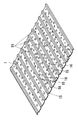
また波板状のベース板1の谷部16の上面に凹凸19を設けたことを特徴とすることも好ましい。この場合、施工者がベース板1上に乗ったとき足裏を滑りにくくでき、施工者の滑落を防止できる。
【0014】
また波板状のベース板1の軒棟方向の端部に谷部18の底部と面一の平面部20を左右方向に亙って設け、軒側の平面部20の軒側端に軒側の平面部20と棟側の平面部20との間の波板形状と同じ波板形状の部分を設けたことを特徴とすることも好ましい。このようにしたことで、ベース板1とこのベース板1より軒先側の屋根瓦6との間及びこのベース板1より棟側の屋根瓦6との間への強風時の雨水の吹き込みを防止できる。またベース板1の山部15の強度が向上するためにビス、釘等の固着具18による固着時における山部15の潰れを防止できる。
【0015】
【発明の実施の形態】
金属板で形成せるベース板1は全体は矩形状であるが、左右方向に山部15と谷部16とが交互に設けてある。本例の場合、山部15や谷部16は台形状に形成されており、山部15や谷部16は軒棟方向に亙るように設けてある。このベース板1の軒棟方向の端部の適所には取り付け金具3が装着されている。この取り付け金具3は山部15の位置で装着されるものであり、山部15に取り付け金具3の下面を沿わせ、下からビスのような固着具23を打入したりして固定される。
【0016】
取り付け金具3には図8に示すように軒先側に取り付けられる軒側取り付け金具3aと棟側に取り付けられる棟側取り付け金具3bとがあり、軒側取り付け金具3aにはコ字状の嵌合溝30を設けてあり、棟側取り付け金具3bには断面L字状の段部31を設けてある。
【0017】
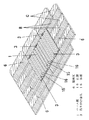
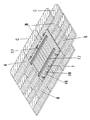
屋根は野地板のような屋根下地13の上にスレート製の平板瓦のような屋根瓦6を図1に示すように軒側から棟側に順に葺いてある。ここで符号Bで示す部分は屋根瓦6の曝露部、符号Cで示す部分は被曝露部である。このように屋根瓦6を葺いた屋根面の上に図1に示すようにベース板1が載置して取り付けられる。ベース板1を取り付けるとき、図2に示すようにチャンネル状の固定フレーム17がベース板1の山部15の上面上に載置される。本例の場合、ベース板1の軒側と棟側とに夫々載置されると共にベース板1の左右方向に亙るように載置される。固定フレーム17を載せた状態で固定フレーム17から図6に示すようにビス、釘等の固着具18が打入され、固着具18が山部15、屋根瓦6を貫通して屋根下地13まで打入され、固定フレーム17でベース板1を押さえるように固定される。このとき、固着具18を貫通させた部分には防水のためにコーキングが施される。
【0018】
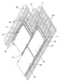
屋根面にベース板1を設置するとき図3に示す屋根面の左右方向及び軒棟方向に複数枚のベース板1が並ぶように設置される。左右に隣り合うベース板1間は一方のベース板1の端部の山部15と他方のベース板1の端部の山部15とを密着するように重ね合わせて接続される。軒棟方向に隣り合うベース板1は軒側に位置するベース板1の棟側の端部に棟側に位置するベース板1の軒側の端部を重ねると共に両ベース板1の山部15同士及び谷部16同士を重ねるように接続される。
このように複数枚のベース板1を取り付け状態で各ベース板1の上には夫々固定フレーム17が載置され、固定フレーム17から夫々固着具18を打入してベース板1が固定される。
【0019】
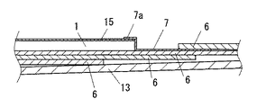
ベース板1とこのベース板1より棟側の屋根瓦6との間は水切り板7で図4、図7に示すように仕舞われる。水切り板7の棟側は軒棟方向に隣り合う屋根瓦9間に差し込まれ、水切り板7の軒側の断面逆L字状の重ね合わせ部7aをベース板1の棟側の端部に重ね合わせてある。屋根機能パネルAとしては本例の場合、太陽電池パネル8が用いられるものであって、各ベース板1の上に太陽電池パネル8が載置され、太陽電池パネル8が図5、図8に示すように取り付け金具3にて取り付けられる。
【0020】
太陽電池パネル8の軒側の端部は軒側取り付け金具3aの嵌合溝30にパッキン材32を介して嵌合してあり、太陽電池パネル8の棟側の端部はパッキン材32を介して段部31に嵌めてある。最も軒側に装着した軒側取り付け金具3aには軒側を全長に亙って覆う軒先側カバー33を配置してあり、ビスのような固着具34にて取り付けてある。最も棟側に装着した棟側取り付け金具3bには棟側を全長に亙って覆う棟側カバー35を配置してあり、この棟側カバー35を固着具34にて棟側取り付け金具3bに取り付けてある。この棟側カバー35は段部31の上方を覆っており、これにより段部31から太陽電池パネル8が脱落しないように止めている。棟側と軒側の中間部では棟側取り付け金具3bと軒側取り付け金具3aとに亙って覆う中間部カバー36を固着具34にて取り付けてあり、この中間部カバー36にて段部31の上方を覆っており、これにより段部31から太陽電池パネル8が脱落しないように止めている。
【0021】
上記のようにして屋根機能パネルAとしての太陽電池パネル8が取り付けられるが、ベース板1として波板形状に成形した板金を用いることで、コストを削減しながら必要な強度が得られる。またベース板1として波板形状に成形した板金を用いることで、ベース板1同士のジョイント(軒棟方向及び左右方向)が重ね合わせて防水を確保でき、施工上やコスト面において非常に有利である。またベース板1として波板形状に成形した板金を用いることで太陽電池パネル8のような屋根機能パネルAを取り付けるための取り付け金具3をベース板1の裏面から直接ビスのような固着具23にて固定することが可能になる。またベース板1を波形形状の板金としたことによりベース板1の重量を軽減でき、施工性が向上する。ベース板1は波板状であるためにベース板1と屋根面との水はけがよくてベース板1と屋根面との間に水が溜まらず汚れや腐食の問題を発生しないようにできる。固定フレーム17からビス、釘等の固着具18をベース板1の山部15、屋根瓦6を介して屋根下地13に打設してベース板1を固定するために固着具18を打入する部分から屋根下地13に雨水が浸入するおそれがないものであり、しかも固定フレーム17上に載設した屋根機能パネルAはベース板1に固定した取り付け金具3で取り付けるために屋根機能パネルAを固定する部分から雨水が一切浸入するおそれのないものであり、屋根下地13や小屋裏に雨水が浸入して腐食したりするおそれがない。
【0022】
またベース板1を固着具18で固着するとき、図9(a)のような構造を採用することも好ましい。ベース板1の山部15の上に固定フレーム17を載せ、固定フレーム17からベース板1、屋根瓦6を介して屋根下地13まで固着具18を打入してベース板が固着されるが、このとき左右方向の端部の1つの山部15より内側の山部15の部分で固着具18を打入している。図9(b)に示すようにベース板1の左右方向の端部に位置する山部15で固着具18を打入して固着すると図9(b)の矢印aのように固着具18を打入した部分から雨水が浸入するおそれがあるが、端部の1山より内側の山部15で固着具18を打入して固着すると、そのようなおそれがなくなる。
【0023】
またベース板1を固着具18で固着するとき、図10(a)のような構造を採用することも好ましい。左右方向に隣り合うベース板1間で端部の山部15同士を重ね合わせるが、この山部15同士を重ね合わせた部分より内側の山部15の位置で固定フレーム17からベース板1、屋根瓦6を介して屋根下地13まで固着具18を打入してベース板1を固定している。図10(b)に示すようにベース板1の端部の山部15同士を重ね合わせて部分に固着グ8を打入すると、ベース板1を重ね合わせた部分に毛細管現象で浸入した雨水が図10(b)の矢印bに示すように固着具18を打入した部分から浸入するおそれがあるが、山部15同士を重ね合わせた部分より内側の山部15の部分で固着具18を打入するとそのようなおそれがなくなる。また隣り合うベース板1の山部15を互いに重ね合わせた部分を固定フレーム17で押さえており、左右に隣り合うベース板1を重ね合わせた部分を固定フレーム17で押さえて左右のベース板1間を一層防水的に接続できるようになっている。
【0024】
またベース板1に図11に示すような構造を採用することも好ましい。この場合、ベース板1の谷部16の上面に凹凸19を設けてある。このようにベース板1の谷部16の上面に凹凸19を設けてあると、施工者が乗った場合においても滑りにくくなり、滑落を防止できる。またベース板1同士の滑りも防止できる。またベース板1と屋根瓦6とが密着する部分に、台風時などに雨水がその隙間に吹き込んだ場合においても、凹凸19にて密着部分に水が溜まりにくくなり、ベース板1に錆が生じにくくなる。また上記のようにベース板1と屋根瓦6との間に水が溜まりにくくなるため、屋根瓦6の固定具(ビス、釘等)に欠陥があった場合やベース板1の固着具18を打入した貫通穴に欠陥があった場合でも屋根下地13や小屋裏に漏水するおそれを防止できる。また棟側の水切り板7で接続する箇所も同様に雨水の吹き込みを防止できる。
【0025】
またベース板1は図12に示すような構造を採用することも好ましい。ベース板1に山部15と谷部16を左右方向に交互に設けるとき、軒側及び棟側を端部を除いて設けてある。ベース板1の軒側と棟側とに左右方向に亙って谷部16と面一の平面部20を設けると共に軒側の平面部20と棟側の平面部20との間に軒棟方向に亙って山部15と谷部16とを設けてある。そして軒側の平面部20の軒側端には上記山部15と谷部16とからなる波板形状と同じ波板形状にしてり、軒棟方向の長さの短い山部15′と谷部16′を左右方向に交互に設けてある。このベース板15には取り付け金具3を取着する場合、山部15の棟側の端部の近傍と山部15′にビス等の固着具23で取り付けてある。
【0026】
このような構造のベース板1も図13(a)に示すように屋根瓦6を吹いた屋根面の上にベース板1が載置され、図13(b)に示すようにベース板1の上に固定フレーム17が載置され、固定フレーム17から固着具18が打入されて固定される。そして図13(c)に示すように複数枚のベース板1が左右方向及び軒棟方向に並べて敷設され、左右に隣り合うベース板1の端部の同士は重ね合わせられ、軒棟方向に隣り合うベース板1の平面部20同士は重ね合わせられる。平面部20の重ね合わせたとき、山部15の棟側端部に山部15′が重ね合わせられる。次いで図13(d)に示すように水切り板7でベース板1の棟側が仕舞われ、図13(e)に示すようにベース板1の上に屋根機能パネルAとしての太陽電池パネル8が取り付け金具3にて取り付けられる。
【0027】
上記のように軒棟方向の端部が平面部20とし、平面部20間を山部15と谷部16からなる波板形状としたことにより、軒先側に設置するベース板1の軒先端と屋根瓦6との間に強風時に雨水が入り込むのを防止でき、また水切り板7で仕舞う箇所にも同様に雨水の吹き込みを防止できる。また軒棟方向の端部を平面部20とし、平面部20間を山部15と谷部16からなる波板形状としたことにより、山部15の強度が向上するため、固定フレーム17で押さえて固定した際、
固着具18の締め付けによる山部15の潰れを防止できる。また軒先側の平面部20の軒先端に山部15′を設けたことにより、軒側が平面部20であっても山部15′を利用して取り付け金具3をビスのような固着具23にて山部15′の裏面側から固定が可能になり、また山部15′と谷部16′を設けたことにより、軒棟方向に隣り合うベース板1の位置決めが容易になり、施工性や施工精度が向上する。
【0028】
上記の例では屋根機能パネルAとして太陽電池パネル8を取り付けるものについて述べたが、この太陽電池パネル8の代わりに植物25を植えた緑化パネル26を太陽電池パネル8と同様にベース板1上に取り付け金具3にて取り付けてもよい。この緑化パネル26は図14に示すように排水性や通気性を有するトレイ状のパネル本体27に培土28を入れ、コケ類等の植物25を植えたものである。緑化パネルAを屋根に設置すると、屋根の緑化ができる。このとき波板形状のベース板1の上に緑化パネル26を取り付けているので、排水が容易になり、万が一コケ類等の植物25の根が伸びてもベース板1によって屋根瓦6まで延びるのを防止でき、植物25の根によって屋根瓦6が割れるのを防止できる。
【0029】
また、このように屋根の上に取り付ける屋根機能パネルAとしては、太陽電池パネル8、緑化パネル26以外に、太陽熱集熱パネル等があり、同様に施工することができる。
【0030】
【発明の効果】
本発明の請求項1の発明は、左右方向に山部と谷部とを交互に設けた金属の波板状のベース板を屋根瓦の上に載設し、山部や谷部の長手方向と直交する方向に長手方向が向く金属の固定フレームをベース板の山部上にベース板の左右方向に亙るように載置し、固定フレームからビス、釘等の固着具をベース板の山部、屋根瓦を介して屋根下地まで打設して固定フレームとベース板とを固定し、固定フレームを介してベース板上に太陽電池パネル、太陽熱集熱パネル、緑化パネル等の屋根機能パネルを載置し、ベース板に固定した取り付け金具で屋根機能パネルの周縁を固定したものであって、山部と谷部を交互に設けた金属の波板状のベース板を用いているので、板厚を厚くしたりすることなくベース板の剛性を上げることができ、コストを削減しながら必要な強度が得られると共に、ベース板の重量を軽減できて施工性が向上できるものであり、しかもベース板は波板状であるためにベース板と屋根面との水はけがよくてベース板と屋根面との間に水が溜まらず汚れや腐食の問題を発生しないようにできるものであり、さらに固定フレームからビス、釘等の固着具をベース板の山部、屋根瓦を介して屋根下地に打設してベース板を固定するために固着具を打入する部分から屋根下地や小屋裏に雨水が浸入するおそれがないものであり、さらに固定フレーム上に載設した屋根機能パネルはベース板に固定した取り付け金具で押さえて取り付けるために屋根機能パネルを固定する部分から雨水が一切浸入するおそれのないものであり、屋根下地や小屋裏に雨水が浸入して腐食したりするおそれがないものである。
【0031】
また本発明の請求項2の発明は、請求項1において、波板状のベース板を左右に複数枚並べ、左右に隣り合うベース板間で左右のベース板の波板形状を互い重ね合わせて接続したので、左右に隣り合うベース板の左右の端部を重ね合わせることにより防水的に接続できるものである。
【0032】
また本発明の請求項3の発明は、請求項1または請求項2において、波板状のベース板を軒棟方向に複数枚並べ、軒棟方向に隣り合うベース板間で両ベース板の波板形状を互いに重ね合わせて接続したので、軒棟方向に隣り合うベース板の端部間を防水的に接続できると共に軒棟方向に隣り合うベース板を左右方向に容易に位置決めできるものである。
【0033】
また本発明の請求項4の発明は、請求項1乃至請求項3のいずれかにおいて、ベース板の左右方向の端部の少なくとも1つの山部を越えた内側の位置で固定フレームからビス、釘等の固着具をベース板の山部、屋根瓦を介して屋根下地まで打設したので、ベース板の左右方向の端部から離れた位置で固着具を打設することにより、固着具を打設する位置まで水が浸入しにくく、固着具を打入した部分から一層屋根下地や小屋裏に雨水が浸入するおそれがなくなるものである。
【0034】
また本発明の請求項5の発明は、請求項1乃至請求項4のいずれかにおいて、左右に隣り合うベース板の互いに重ね合わせた部分を固定フレームで押さえたので、左右に隣り合うベース板を重ね合わせた部分を固定フレームで押さえて左右のベース板間を一層防水的に接続できるものである。
【0035】
また本発明の請求項6の発明は、請求項1乃至請求項5のいずれかにおいて、波板状のベース板の谷部の上面に凹凸を設けたので、施工者がベース板上に乗ったとき足裏を滑りにくくでき、施工者の滑落を防止できるものである。
【0036】
また本発明の請求項7の発明は、請求項1乃至請求項6のいずれかにおいて、波板状のベース板の軒棟方向の端部に谷部の底部と面一の平面部を左右方向に亙って設け、軒側の平面部の下端に軒側の平面部と棟側の平面部との間の波板形状と同じ波板形状の部分を設けたので、ベース板とこのベース板より軒先側の屋根瓦との間及びこのベース板より棟側の屋根瓦との間への強風時の雨水の吹き込みを防止できるものであり、しかもベース板の山部の強度が向上するためにビス、釘等の固着具による固着時における山部の潰れを防止できるものである。
【図面の簡単な説明】
【図1】本発明の実施の形態の一例の施工状態を説明する斜視図である。
【図2】図1の次の施工施工状態を説明する斜視図である。
【図3】図2の次の施工状態を説明する斜視図である。
【図4】図3の次の施工状態を説明する斜視図である。
【図5】図4の次の施工状態を説明する斜視図である。
【図6】同上のベース板を固着具で固着した部分を示す断面図である。
【図7】同上の水切り板で仕舞った部分を示す断面図である。
【図8】(a)は同上の太陽電池パネルを取り付けた状態を示す一部切欠断面図、(b)は要部の分解斜視図である。
【図9】(a)は同上のベース板を固着具で固着する状態を示す断面図、(b)は比較例を示す断面図である。
【図10】(a)は同上のベース板を固着具で固着する状態を示す断面図、(b)は比較例を示す断面図である。
【図11】同上のベース板の他の例を示す斜視図である。
【図12】同上のベース板の他の例を示す斜視図である。
【図13】(a)(b)(c)(d)(e)は図12のベース板を用いて施工する状態を示す斜視図である。
【図14】同上の緑化パネルを示す一部切欠断面図である。
【図15】(a)(b)(c)(d)(e)は一従来例の施工状態を示す斜視図である。
【図16】(a)は他の従来例を説明する斜視図、(b)は要部の断面図である。
【符号の説明】
A 屋根機能パネル
1 ベース板
3 取り付け金具
6 屋根瓦
8 太陽電池パネル
13 屋根下地
15 山部
16 谷部
17 固定フレーム
18 固着具
19 凹凸
20 平面部
26 緑化パネル
[0001]
TECHNICAL FIELD OF THE INVENTION
The present invention relates to a structure for mounting a roof functional panel such as a solar cell panel, a solar heat collecting panel, and a greening panel on a roof tile of a roof.
[0002]
[Prior art]
Conventionally, as an example of installing a solar cell panel on a roof tile of a roof, for example, there is one shown in FIG. As shown in FIG. 15 (a), mounting holes 2 are drilled at four corners of a flat base plate 1 'made of metal in a rectangular shape, and mounting brackets 3 are screwed into the mounting holes 2 by screws. ). Next, the base plate 1 'is placed on a roof surface on which a roof tile such as a flat tile is roofed, and a fixing tool 4 such as a nail or a screw is punched from a slit-shaped fixing hole provided in the base plate 1' to the base of the roof. Insert and fix. At this time, a plurality of base plates 1 'are laid side by side on the roof surface, but the base plates 1' adjacent in the eaves ridge direction of the roof surface are stopped by overlapping, and the base plates 1 'adjacent on the left and right sides. The space is stopped using a joiner or a discarded sheet metal. The part into which the fixing tool 4 is driven is covered with the cover member 5 as shown in FIG. Water is stopped by a drain plate 7 between the ridge side end of the base plate 1 'and the roof tile 6 on the ridge side. In this manner, the solar cell panels 8 are arranged on each base plate 1 'with the base plate 1' mounted on the roof surface, and the solar cell panels 8 are mounted on the base plate 1 '.
[0003]
Another conventional example of installing a solar cell panel on a roof tile of a roof is shown in FIG. 16 (for example, see Patent Document 1). The solar cell panel 8 is fitted and mounted on a frame member 9 having a rectangular frame, and legs 10 are provided at four corners of the frame member 9 so as to protrude downward. A mounting hole 11 is formed so as to reach the lower end of the leg 10. Then, the frame member 9 is installed on the roof surface by placing the lower ends of the legs 10 on the roof surface, and the fixing screws 12 are inserted from the mounting holes 11 to the roof base 13 under the roof tile 6 to secure the fixing screws. 12, the frame member 9 is fixed.
[0004]
[Patent Document 1]
JP-A-11-131732
[0005]
[Problems to be solved by the invention]
In the case of the conventional example shown in FIG. 15 described above, the roof tile 6 such as a flat tile is laid, and the roof tile 6 adjacent to the eaves ridge direction has a step corresponding to the thickness of the roof tile 6 on the roof surface. The base plate 1 needs a certain degree of rigidity to mount the plate 1 ', but the base plate 1 of the above-mentioned conventional example has a small rigidity because it is simply a flat plate. In order to impart rigidity to the flat base plate 1 ', it is necessary to increase the plate thickness. However, if the plate thickness is increased, there is a problem in that the cost and weight of the members increase. In addition, when the flat base plate 1 'is installed on the roof surface, there is a problem that drainage between the base plate 1' and the roof surface is poor and causes dirt and corrosion. Further, in the case of a flat base plate 1 ', there is a problem that the structure for stopping water between the base plates 1' adjacent on the left and right becomes complicated. There is).
[0006]
In addition, in the case of the conventional example shown in FIG. 16 described above, since the frame member 9 is mounted on the leg portion 10 so as to float above the roof surface, a gap is formed between the solar cell panel 8 and the frame member 9 to drain water. However, there is a problem that the frame member 9 needs rigidity due to the structure in which the entire frame member 9 is lifted and supported by the legs 10, and the weight of the frame member 9 increases. Further, the fixing screw 12 inserted from the mounting hole 11 is screwed to the roof base 13 via the roof tile 6. In this case, when the fixing screw 12 is fixed in this manner, the mounting hole 11 and the fixing screw 12 are removed from above the frame member 9. There is a possibility that rainwater may penetrate into the roof foundation 13 via the roof, and the roof foundation may rot.
[0007]
The present invention has been made in view of the above points, and can be stably supported by a highly rigid base plate, and can be well drained between a base plate and a roof surface. It is an object of the present invention to provide a mounting structure for a roof functional panel that can be easily mounted and can be mounted so that water does not enter the roof foundation.
[0008]
[Means for Solving the Problems]
In order to solve the above-mentioned problem, the roof functional panel mounting structure according to the present invention is configured such that a metal corrugated base plate 1 provided with alternating ridges 15 and valleys 16 in the left-right direction is placed on a roof tile 6. A metal fixed frame 17 whose longitudinal direction is perpendicular to the longitudinal direction of the ridges 15 and the valleys 16 is placed on the ridges 15 of the base plate 1 so as to extend in the left-right direction of the base plate 1. Then, a fixing tool 18 such as a screw or a nail is driven from the fixing frame 17 to the roof base 13 via the crest of the base plate 1 and the roof tile 6 to fix the fixing frame 17 and the base plate 1 to each other. A roof function panel A such as a solar cell panel 8, a solar heat collecting panel, and a greening panel 26 is placed on the base plate 1 via the base plate 17, and the periphery of the roof function panel A is fixed to the mounting bracket 3 fixed to the base plate 1. It is characterized by being fixed. As described above, the rigidity of the base plate 1 can be increased without increasing the plate thickness by using the metal corrugated base plate 1 in which the peaks 15 and the valleys 16 are provided alternately. The required strength can be obtained while reducing the cost, and the weight of the base plate 1 can be reduced, so that the workability can be improved. Since the base plate 1 is corrugated, drainage between the base plate 1 and the roof surface is good, so that water does not accumulate between the base plate 1 and the roof surface, thereby preventing problems such as dirt and corrosion. A fixing tool 18 such as a screw or a nail is driven from the fixing frame 17 into the roof foundation 13 via the crest 15 of the base plate 1 and the roof tile 6, and the fixing tool 18 is driven to fix the base plate 1. The roof functional panel A mounted on the fixed frame 17 is fixed to the roof functional panel A for mounting with the mounting bracket 3 fixed to the base plate 1 without the possibility of rainwater infiltrating into the roof foundation 13 from the part. There is no danger of rainwater infiltrating from the part where the rainwater flows, and there is no danger of rainwater penetrating into the roof foundation 13 or the back of the hut and corroding.
[0009]
It is also preferable that a plurality of corrugated base plates 1 are arranged on the left and right, and the corrugated plate shapes of the right and left base plates 1 are connected to each other between the base plates 1 adjacent on the left and right. In this way, by connecting the left and right ends of the base plates 1 adjacent to each other on the left and right, a waterproof connection can be achieved.
[0010]
In addition, a plurality of corrugated base plates 1 are arranged in the eaves ridge direction, and the corrugated plate shapes of both base plates 1 are connected to each other between the base plates 1 adjacent in the eaves ridge direction. preferable. In this way, the ends of the base plates 1 adjacent in the eaves ridge direction can be waterproofly connected, and the base plates 1 adjacent in the eaves ridge direction can be easily positioned in the left-right direction.
[0011]
At the inner position beyond at least one crest 15 at the end in the left-right direction of the base plate 1, a fixing tool 18 such as a screw or a nail is attached from the fixed frame 17 via the crest 15 of the base plate 1 and the roof tile 6. It is also preferable to be characterized in that it has been driven down to the roof base 13. In this case, the fastener 18 is cast at a position away from the end in the left-right direction of the base plate 1, so that water hardly penetrates to the position where the fastener 18 is to be cast, and the portion where the fastener 18 is driven is provided. This further eliminates the possibility that rainwater will enter the roof foundation 13 and the back of the hut.
[0012]
It is also preferable that the overlapping portions of the base plates 1 adjacent to each other on the left and right are pressed by the fixed frame 17. In this case, the portion where the left and right adjacent base plates 1 are overlapped is pressed by the fixed frame 17 so that the left and right base plates 1 can be connected more waterproofly.
[0013]
It is also preferable that irregularities 19 are provided on the upper surface of the valleys 16 of the corrugated base plate 1. In this case, it is possible to prevent the sole from slipping on the sole when the constructor rides on the base plate 1, and to prevent the constructor from slipping off.
[0014]
At the end of the corrugated base plate 1 in the eaves ridge direction, a flat portion 20 flush with the bottom of the valley 18 is provided in the left-right direction. It is also preferable to provide a corrugated portion having the same shape as the corrugated plate between the flat portion 20 and the flat portion 20 on the ridge side. By doing so, it is possible to prevent rainwater from being blown during a strong wind between the base plate 1 and the roof tile 6 on the eaves side of the base plate 1 and between the base plate 1 and the roof tile 6 on the ridge side. it can. In addition, since the strength of the ridge 15 of the base plate 1 is improved, the ridge 15 can be prevented from being crushed when fixed by the fixing tool 18 such as a screw or a nail.
[0015]
BEST MODE FOR CARRYING OUT THE INVENTION
The base plate 1 formed of a metal plate has a rectangular shape as a whole, but peaks 15 and troughs 16 are provided alternately in the left-right direction. In the case of this example, the peaks 15 and the valleys 16 are formed in a trapezoidal shape, and the peaks 15 and the valleys 16 are provided so as to extend in the eaves ridge direction. A mounting bracket 3 is mounted at an appropriate position at an end of the base plate 1 in the eaves ridge direction. The mounting bracket 3 is mounted at the position of the peak 15, the lower surface of the mounting bracket 3 is arranged along the peak 15, and the mounting bracket 3 such as a screw is driven in from below to be fixed. .
[0016]
As shown in FIG. 8, the mounting bracket 3 includes an eave-side mounting bracket 3a mounted on the eaves side and a ridge-side mounting bracket 3b mounted on the ridge side. 30 is provided, and the ridge-side mounting bracket 3b is provided with a step 31 having an L-shaped cross section.
[0017]
As for the roof, a roof tile 6 such as a slate flat tile is laid on a roof foundation 13 such as a field board in order from the eaves side to the ridge side as shown in FIG. Here, a portion indicated by reference numeral B is an exposed portion of the roof tile 6, and a portion indicated by reference numeral C is an exposed portion. As shown in FIG. 1, the base plate 1 is placed and mounted on the roof surface on which the roof tile 6 is laid. When the base plate 1 is attached, a channel-shaped fixed frame 17 is placed on the upper surface of the ridge 15 of the base plate 1 as shown in FIG. In the case of this example, the base plate 1 is placed on the eaves side and the ridge side, respectively, and is placed so as to extend in the left-right direction of the base plate 1. As shown in FIG. 6, a fixing tool 18 such as a screw or a nail is driven from the fixing frame 17 with the fixing frame 17 placed thereon, and the fixing tool 18 penetrates the mountain 15 and the roof tile 6 to the roof base 13. The base plate 1 is pressed and fixed by the fixing frame 17. At this time, caulking is applied to a portion where the fixing tool 18 is penetrated for waterproofing.
[0018]
When the base plate 1 is installed on the roof surface, a plurality of base plates 1 are arranged in the left-right direction and the eaves ridge direction of the roof surface shown in FIG. The base plates 1 adjacent to each other on the left and right are connected to each other so that the crests 15 at the end of one base plate 1 and the crests 15 at the end of the other base plate 1 are in close contact with each other. The base plate 1 adjacent to the eave ridge direction overlaps the eave-side end of the base plate 1 located on the ridge side with the ridge-side end of the base plate 1 located on the eave side, and the crests 15 of both base plates 1. The valleys 16 are connected so as to overlap each other.
As described above, the fixed frames 17 are mounted on the respective base plates 1 with the plurality of base plates 1 attached, and the fixing members 18 are driven into the respective fixed frames 17 to fix the base plates 1. .
[0019]
A drain plate 7 is provided between the base plate 1 and the roof tile 6 on the ridge side of the base plate 1 as shown in FIGS. The ridge side of the draining board 7 is inserted between the roof tiles 9 adjacent to each other in the eaves ridge direction, and the eaves-side overlapping section 7a of the draining board 7 is overlapped on the ridge side end of the base plate 1. It is matched. In this example, the solar cell panel 8 is used as the roof functional panel A, and the solar cell panel 8 is mounted on each base plate 1, and the solar cell panel 8 is shown in FIGS. As shown, it is attached with the attachment fitting 3.
[0020]
The eave-side end of the solar cell panel 8 is fitted into the fitting groove 30 of the eave-side mounting bracket 3a via a packing material 32, and the ridge-side end of the solar cell panel 8 is provided via a packing material 32. It is fitted to the step 31. An eaves-side cover 33 that covers the eaves over the entire length is disposed on the eaves-side mounting bracket 3a mounted on the most eaves side, and is attached with a fixing tool 34 such as a screw. A ridge side cover 35 that covers the ridge side over the entire length is disposed on the ridge side mounting bracket 3b attached to the most ridge side, and the ridge side cover 35 is attached to the ridge side mounting bracket 3b with the fixing member 34. It is. The ridge-side cover 35 covers the upper part of the step 31, thereby stopping the solar cell panel 8 from falling off the step 31. At an intermediate portion between the ridge side and the eaves side, an intermediate portion cover 36 that covers the ridge side mounting bracket 3b and the eaves side mounting bracket 3a is attached with a fixing member 34. , So that the solar cell panel 8 is prevented from falling off from the stepped portion 31.
[0021]
The solar cell panel 8 as the roof functional panel A is attached as described above. By using a sheet metal formed into a corrugated sheet shape as the base plate 1, required strength can be obtained while reducing costs. Also, by using a sheet metal formed into a corrugated sheet shape as the base plate 1, the joints (the eaves building direction and the left and right direction) of the base plates 1 can be overlapped to ensure waterproofing, which is very advantageous in construction and cost. is there. Further, by using a sheet metal formed into a corrugated sheet shape as the base plate 1, the mounting bracket 3 for mounting the roof functional panel A such as the solar cell panel 8 is directly attached to the fixing member 23 such as a screw from the back surface of the base plate 1. Can be fixed. In addition, since the base plate 1 is formed of a corrugated sheet metal, the weight of the base plate 1 can be reduced, and workability is improved. Since the base plate 1 is corrugated, drainage between the base plate 1 and the roof surface is good, so that water does not accumulate between the base plate 1 and the roof surface, thereby preventing problems such as dirt and corrosion. A fixing tool 18 such as a screw or a nail is driven from the fixing frame 17 into the roof foundation 13 via the crest 15 of the base plate 1 and the roof tile 6, and the fixing tool 18 is driven to fix the base plate 1. The roof functional panel A mounted on the fixed frame 17 is fixed to the roof functional panel A for mounting with the mounting bracket 3 fixed to the base plate 1 without the possibility of rainwater infiltrating into the roof foundation 13 from the part. There is no danger of rainwater infiltrating from the part where the rainwater flows, and there is no danger of rainwater penetrating into the roof foundation 13 or the back of the hut and corroding.
[0022]
When the base plate 1 is fixed by the fixing member 18, it is preferable to adopt a structure as shown in FIG. The fixing frame 17 is placed on the crest 15 of the base plate 1, and the fixing tool 18 is driven from the fixing frame 17 to the roof foundation 13 through the base plate 1 and the roof tile 6 to fix the base plate. At this time, the fastener 18 is driven into the ridge 15 inside one ridge 15 at the end in the left-right direction. As shown in FIG. 9B, when the fixing tool 18 is driven into and fixed at the ridge 15 located at the end in the left-right direction of the base plate 1, the fixing tool 18 is moved as indicated by an arrow a in FIG. 9B. Although there is a possibility that rainwater may enter from the part where it is driven in. However, if the fixing tool 18 is driven in and fixed at the crest 15 inside one crest at the end, such a danger is eliminated.
[0023]
When the base plate 1 is fixed by the fixing member 18, it is preferable to adopt a structure as shown in FIG. The ridges 15 at the ends are overlapped between the base plates 1 adjacent to each other in the left-right direction. At the position of the ridges 15 inside the portion where the ridges 15 are overlapped, the fixed frame 17 and the base plate 1, The fixing plate 18 is driven into the roof foundation 13 via the tile 6 to fix the base plate 1. As shown in FIG. 10 (b), when the ridges 15 at the ends of the base plate 1 are overlapped with each other and the fixing group 8 is driven into the portion, the rainwater that has infiltrated into the portion where the base plate 1 is overlapped by the capillary phenomenon is generated. As shown by an arrow b in FIG. 10B, there is a possibility that the fastener 18 may enter from a portion where the fastener 18 is driven, but the fastener 18 is attached at a portion of the peak 15 inside the portion where the peaks 15 are overlapped. Such a fear disappears when it is driven. Further, a portion where the crests 15 of the adjacent base plates 1 overlap each other is held by the fixed frame 17, and a portion where the adjacent base plates 1 are overlapped on the left and right is held by the fixed frame 17 so that the left and right base plates 1 Can be connected more waterproofly.
[0024]
It is also preferable to employ a structure as shown in FIG. In this case, unevenness 19 is provided on the upper surface of the valley 16 of the base plate 1. When the unevenness 19 is provided on the upper surface of the valley portion 16 of the base plate 1 as described above, it becomes difficult for the builder to slip even when riding on the builder, and it is possible to prevent slipping. Also, slippage between the base plates 1 can be prevented. Also, even when rainwater blows into the gap between the base plate 1 and the roof tile 6 in the event of a typhoon or the like, water is less likely to accumulate in the tightly contacted portion due to the unevenness 19, and rust occurs on the base plate 1. It becomes difficult. In addition, since it is difficult for water to collect between the base plate 1 and the roof tile 6 as described above, if the fixing device (such as a screw or a nail) of the roof tile 6 has a defect or the fixing device 18 of the base plate 1 Even if there is a defect in the penetrated through hole, it is possible to prevent the water from leaking into the roof base 13 or the back of the cabin. In addition, it is also possible to prevent rainwater from being blown into the place connected by the drain board 7 on the ridge side.
[0025]
It is also preferable that the base plate 1 has a structure as shown in FIG. When the crests 15 and the valleys 16 are alternately provided on the base plate 1 in the left-right direction, the eaves side and the ridge side are provided except for the ends. A flat portion 20 flush with the valley portion 16 is provided on the eaves side and the ridge side of the base plate 1 in the left-right direction, and the eaves ridge direction is provided between the eaves side flat portion 20 and the ridge side flat portion 20. A peak 15 and a valley 16 are provided. The eave-side end of the eaves-side flat portion 20 has the same corrugated plate shape as the corrugated plate composed of the peaks 15 and the valleys 16. Portions 16 'are provided alternately in the left-right direction. When the mounting bracket 3 is attached to the base plate 15, it is attached to the vicinity of the ridge-side end of the ridge 15 and the ridge 15 'with a fixing tool 23 such as a screw.
[0026]
As shown in FIG. 13A, the base plate 1 having such a structure is mounted on the roof surface on which the roof tile 6 has been blown, and as shown in FIG. The fixing frame 17 is placed on the upper side, and the fixing tool 18 is driven into the fixing frame 17 and fixed. Then, as shown in FIG. 13 (c), a plurality of base plates 1 are laid side by side in the left-right direction and in the eaves ridge direction. The flat portions 20 of the mating base plates 1 are overlapped. When the flat portions 20 are overlapped, the ridge 15 ′ is overlapped with the ridge-side end of the ridge 15. Next, as shown in FIG. 13 (d), the ridge side of the base plate 1 is closed by the drain plate 7, and a solar cell panel 8 as a roof functional panel A is mounted on the base plate 1 as shown in FIG. 13 (e). It is attached with the fitting 3.
[0027]
As described above, the end in the eave ridge direction is the flat portion 20 and the corrugated plate shape including the peak portion 15 and the valley portion 16 is formed between the flat portions 20, so that the eave tip of the base plate 1 installed on the eave tip side can be used. It is possible to prevent rainwater from entering between the roof tile 6 and the wind when the wind is strong, and it is also possible to prevent rainwater from being blown into the area covered by the drain plate 7. In addition, the end in the eaves ridge direction is a flat portion 20, and a corrugated plate shape including a peak portion 15 and a valley portion 16 between the flat portions 20 enhances the strength of the peak portion 15. When fixed
It is possible to prevent the ridge 15 from being crushed due to the fastening of the fixing member 18. Also, since the crest 15 'is provided at the tip of the eaves-side flat portion 20, the mounting bracket 3 is attached to the fixing member 23 such as a screw using the crest 15' even if the eaves is the flat portion 20. The fixing of the base plate 1 adjacent to the eaves ridge direction is facilitated by the provision of the peak portion 15 'and the valley portion 16'. Construction accuracy is improved.
[0028]
In the above example, the solar cell panel 8 is attached as the roof function panel A. However, a greening panel 26 in which a plant 25 is planted in place of the solar cell panel 8 is provided on the base plate 1 similarly to the solar cell panel 8. The mounting bracket 3 may be used. As shown in FIG. 14, the greening panel 26 is obtained by putting cultivated soil 28 into a tray-like panel body 27 having drainage and air permeability, and planting plants 25 such as moss. When the greening panel A is installed on the roof, the roof can be greened. At this time, since the greening panel 26 is mounted on the corrugated base plate 1, drainage becomes easy, and even if the root of the plant 25 such as moss grows, it extends to the roof tile 6 by the base plate 1. Can be prevented, and the roof tile 6 can be prevented from being broken by the root of the plant 25.
[0029]
The roof functional panel A mounted on the roof in this way includes a solar heat collecting panel and the like in addition to the solar cell panel 8 and the greening panel 26, and can be similarly constructed.
[0030]
【The invention's effect】
According to the invention of claim 1 of the present invention, a metal corrugated base plate provided with alternating peaks and valleys in the left-right direction is placed on a roof tile, and the longitudinal direction of the peaks and valleys is set. A metal fixing frame whose longitudinal direction is perpendicular to the base plate is placed on the crest of the base plate so as to extend in the left-right direction of the base plate, and fixing tools such as screws and nails are attached from the fixing frame to the crest of the base plate. The fixed frame and the base plate are fixed by driving down to the roof base through the roof tile, and the roof functional panel such as a solar cell panel, a solar heat collecting panel, and a greening panel is mounted on the base plate via the fixed frame. The roof functional panel is fixed at its periphery with mounting brackets fixed to the base plate, and a metal corrugated base plate with alternating peaks and valleys is used. The rigidity of the base plate can be increased without increasing the The required strength can be obtained while reducing the weight, and the workability can be improved by reducing the weight of the base plate, and because the base plate is corrugated, drainage between the base plate and the roof surface is good. It prevents water from collecting between the base plate and the roof surface, and prevents problems such as dirt and corrosion.Furthermore, fixing tools such as screws and nails are fixed from the fixed frame via the base plate peaks and roof tiles. There is no danger of rainwater entering the roof base or the back of the hut from the part where the fastener is driven to fix it on the roof base and fix the base plate, and the roof function mounted on the fixed frame Since the panel is held down by the mounting bracket fixed to the base plate, there is no danger of rainwater entering the roof functional panel at the part where the roof functional panel is fixed. Fear is that there is no.
[0031]
According to a second aspect of the present invention, in the first aspect, a plurality of corrugated base plates are arranged on the left and right, and the corrugated plate shapes of the left and right base plates are overlapped between the base plates adjacent to the left and right. Since the connection is made, the left and right ends of the base plates adjacent to each other on the left and right can be connected in a waterproof manner by overlapping.
[0032]
According to a third aspect of the present invention, in the first or second aspect, a plurality of corrugated base plates are arranged in the eaves ridge direction, and the waves of the two base plates are interposed between the base plates adjacent in the eaves ridge direction. Since the plate shapes are overlapped and connected, the ends of the base plates adjacent in the eaves ridge direction can be connected in a waterproof manner, and the base plates adjacent in the eaves ridge direction can be easily positioned in the left-right direction.
[0033]
The invention according to a fourth aspect of the present invention is the invention according to any one of the first to third aspects, wherein a screw or a nail is provided from the fixed frame at a position inside at least one ridge of the left and right ends of the base plate. Since the fasteners such as are mounted on the base plate and the roof base through the roof tiles, the fasteners are cast at a position distant from the left and right ends of the base plate. Water is less likely to infiltrate to the installation position, and there is no longer a possibility that rainwater will infiltrate into the roof base or the back of the hut from the part where the fastener is driven.
[0034]
According to a fifth aspect of the present invention, in any one of the first to fourth aspects, the mutually overlapping portions of the base plates adjacent to each other are pressed by the fixed frame. The left and right base plates can be more waterproofly connected by holding the overlapped portion with a fixed frame.
[0035]
Further, in the invention of claim 6 of the present invention, in any one of claims 1 to 5, the unevenness is provided on the upper surface of the valley portion of the corrugated base plate, so that the installer got on the base plate. Sometimes the sole of the foot can be made less slippery, which can prevent the installer from slipping off.
[0036]
According to a seventh aspect of the present invention, in any one of the first to sixth aspects, a flat portion that is flush with the bottom of the valley is formed at the end of the corrugated base plate in the eaves ridge direction. The base plate and the base plate are provided at the lower end of the eaves-side flat portion at the lower end of the eaves-side flat portion and the ridge-side flat portion. In order to prevent rainwater from being blown during strong winds between the roof tiles on the eaves side and between the roof tiles on the ridge side from the base plate, and to improve the strength of the base plate peaks. It is possible to prevent the ridge from being crushed at the time of fixing with a fixing tool such as a screw or a nail.
[Brief description of the drawings]
FIG. 1 is a perspective view illustrating a construction state of an example of an embodiment of the present invention.
FIG. 2 is a perspective view for explaining a state following the execution of FIG. 1;
FIG. 3 is a perspective view illustrating a construction state next to FIG. 2;
FIG. 4 is a perspective view illustrating a construction state next to FIG. 3;
FIG. 5 is a perspective view illustrating a construction state next to FIG. 4;
FIG. 6 is a cross-sectional view showing a portion where the base plate is fixed with a fixing tool.
FIG. 7 is a cross-sectional view showing a part finished by the drain plate of the above.
FIG. 8A is a partially cutaway sectional view showing a state where the solar cell panel is attached, and FIG. 8B is an exploded perspective view of a main part.
9A is a cross-sectional view showing a state where the base plate is fixed by a fixing tool, and FIG. 9B is a cross-sectional view showing a comparative example.
10A is a cross-sectional view showing a state in which the base plate is fixed by a fixing tool, and FIG. 10B is a cross-sectional view showing a comparative example.
FIG. 11 is a perspective view showing another example of the above base plate.
FIG. 12 is a perspective view showing another example of the above base plate.
13 (a), (b), (c), (d), and (e) are perspective views showing a state where construction is performed using the base plate of FIG.
FIG. 14 is a partially cutaway sectional view showing the greening panel of the above.
FIGS. 15 (a), (b), (c), (d), and (e) are perspective views showing a construction state of one conventional example.
16A is a perspective view illustrating another conventional example, and FIG. 16B is a cross-sectional view of a main part.
[Explanation of symbols]
A Roof function panel
1 Base plate
3 Mounting bracket
6 Roof tile
8 Solar panel
13 Roof foundation
15 Yamabe
16 Tanibe
17 Fixed frame
18 Fixture
19 Unevenness
20 flat part
26 Greening panel

Claims (7)

左右方向に山部と谷部とを交互に設けた金属の波板状のベース板を屋根瓦の上に載設し、山部や谷部の長手方向と直交する方向に長手方向が向く金属の固定フレームをベース板の山部上にベース板の左右方向に亙るように載置し、固定フレームからビス、釘等の固着具をベース板の山部、屋根瓦を介して屋根下地まで打設して固定フレームとベース板とを固定し、固定フレームを介してベース板上に太陽電池パネル、太陽熱集熱パネル、緑化パネル等の屋根機能パネルを載置し、ベース板に固定した取り付け金具で屋根機能パネルの周縁を固定したことを特徴とする屋根機能パネルの取り付け構造。A metal corrugated base plate with alternating peaks and valleys in the left-right direction is placed on a roof tile, and metal whose longitudinal direction is perpendicular to the longitudinal direction of the peaks and valleys Is mounted on the base plate so as to extend in the left-right direction of the base plate, and fixing tools such as screws and nails are struck from the fixed frame to the base of the base plate and the roof tile via the roof tile. Mounting bracket that fixes the fixed frame and the base plate, and places the roof functional panel such as a solar cell panel, a solar heat collecting panel, and a greening panel on the base plate via the fixed frame, and fixes it to the base plate. The mounting structure of a roof functional panel, wherein a peripheral edge of the roof functional panel is fixed by the above. 波板状のベース板を左右に複数枚並べ、左右に隣り合うベース板間で左右のベース板の波板形状を互い重ね合わせて接続したことを特徴とする請求項1記載の屋根機能パネルの取り付け構造。2. The roof functional panel according to claim 1, wherein a plurality of corrugated base plates are arranged on the left and right, and the corrugated shapes of the left and right base plates are connected to each other between the base plates adjacent on the left and right. Mounting structure. 波板状のベース板を軒棟方向に複数枚並べ、軒棟方向に隣り合うベース板間で両のベース板の波板形状を互いに重ね合わせて接続したことを特徴とする請求項1または請求項2記載の屋根機能パネルの取り付け構造。A plurality of corrugated base plates are arranged in the eaves ridge direction, and the corrugated plate shapes of the two base plates are connected to each other between the base plates adjacent in the eaves ridge direction, or connected. Item 4. An installation structure for a roof functional panel according to Item 2. ベース板の左右方向の端部の少なくとも1つの山部を越えた内側の位置で固定フレームからビス、釘等の固着具をベース板の山部、屋根瓦を介して屋根下地まで打設したことを特徴とする請求項1乃至請求項3のいずれかに記載の屋根機能パネルの取り付け構造。A fastener such as a screw, a nail, or the like is cast from the fixed frame to the roof base through the mountain of the base plate and the roof tile at a position inside at least one mountain at the end in the left-right direction of the base plate. The mounting structure for a roof functional panel according to any one of claims 1 to 3, characterized in that: 左右に隣り合うベース板の互いに重ね合わせた部分を固定フレームで押さえたことを特徴とする請求項1乃至請求項4のいずれかに記載の屋根機能パネルの取り付け構造。The mounting structure of a roof functional panel according to any one of claims 1 to 4, wherein the overlapping portions of the base plates adjacent to each other on the left and right sides are pressed by a fixing frame. 波板状のベース板の谷部の上面に凹凸を設けたことを特徴とする請求項1乃至請求項5のいずれかに記載の屋根機能パネルの取り付け構造。The mounting structure for a roof functional panel according to any one of claims 1 to 5, wherein irregularities are provided on an upper surface of a valley portion of the corrugated base plate. 波板状のベース板の軒棟方向の端部に谷部の底部と面一の平面部を左右方向に亙って設け、軒側の平面部の軒側端に軒側の平面部と棟側の平面部との間の波板形状と同じ波板形状の部分を設けたことを特徴とする請求項1乃至請求項6のいずれかに記載の屋根機能パネルの取り付け構造。At the end of the corrugated base plate in the direction of the eaves ridge, a flat portion flush with the bottom of the valley is provided in the left-right direction, and the eaves-side flat portion and the ridge are provided at the eaves-side end of the eaves-side flat portion. The mounting structure for a roof functional panel according to any one of claims 1 to 6, wherein a portion having the same corrugated plate shape as the corrugated plate between the flat surface portion on the side is provided.
JP2002373196A 2002-12-24 2002-12-24 Roof functional panel mounting structure Expired - Fee Related JP3829799B2 (en)

Priority Applications (1)

Application Number Priority Date Filing Date Title
JP2002373196A JP3829799B2 (en) 2002-12-24 2002-12-24 Roof functional panel mounting structure

Applications Claiming Priority (1)

Application Number Priority Date Filing Date Title
JP2002373196A JP3829799B2 (en) 2002-12-24 2002-12-24 Roof functional panel mounting structure

Publications (2)

Publication Number Publication Date
JP2004204502A true JP2004204502A (en) 2004-07-22
JP3829799B2 JP3829799B2 (en) 2006-10-04

Family

ID=32811567

Family Applications (1)

Application Number Title Priority Date Filing Date
JP2002373196A Expired - Fee Related JP3829799B2 (en) 2002-12-24 2002-12-24 Roof functional panel mounting structure

Country Status (1)

Country Link
JP (1) JP3829799B2 (en)

Cited By (3)

* Cited by examiner, † Cited by third party
Publication number Priority date Publication date Assignee Title
WO2005119769A1 (en) * 2004-06-04 2005-12-15 Ats Automation Tooling Systems Inc. Method for construction of rigid photovoltaic modules
JP2010110237A (en) * 2008-11-04 2010-05-20 Mbs Inc Greening system, and method for attaching greening panel
JP2014190593A (en) * 2013-03-27 2014-10-06 Sekisui House Ltd Heat collection panel and solar heat collection device

Also Published As

Publication number Publication date
JP3829799B2 (en) 2006-10-04

Similar Documents

Publication Publication Date Title
JP5282118B2 (en) Solar cell module laying method and solar cell module blowing prevention device
JP4010666B2 (en) Solar power plant
US7155870B2 (en) Shingle assembly with support bracket
JP3846654B2 (en) Roof panel with solar cell and roof structure
JP3555719B2 (en) Solar cell mounting equipment
JP3829799B2 (en) Roof functional panel mounting structure
JP3838226B2 (en) Mounting structure of base plate for roof functional panel
JPWO2018061696A1 (en) Solar power generator
JP5136388B2 (en) Green roof tile
JP3494424B2 (en) Solar cell mounting equipment
JP5158783B2 (en) Snow clamp and its construction method
JP2577624B2 (en) Ventilated waterproof structure roof
JP5501741B2 (en) Roof structure for greening on square wave roof and its construction method
JP6364673B2 (en) Corrugated fixing bracket and roof mounting structure
JP5953625B2 (en) How to install the solar system
JP2011144574A (en) Structure of photovoltaic panel-installed roof, and method for constructing the same
JP2010053538A (en) Sloped green roof equipped with skylight window
JPS6313295Y2 (en)
JP2629140B2 (en) Installation structure of solar energy utilization equipment on the roof
JP4822227B2 (en) Greening structure of sloped roof
JP2023110587A (en) Rain flashing ventilation member, and construction structure of the same
JP2006063688A (en) Water treatment structure of and construction method for functional panel installation roof
JP2530563Y2 (en) Keraba roof panel
JP3386453B2 (en) Waterproof connecting member receiving structure and waterproof connecting member
JPH10169129A (en) Roof provided with solar battery

Legal Events

Date Code Title Description
A621 Written request for application examination

Free format text: JAPANESE INTERMEDIATE CODE: A621

Effective date: 20041026

A977 Report on retrieval

Free format text: JAPANESE INTERMEDIATE CODE: A971007

Effective date: 20060614

TRDD Decision of grant or rejection written
A01 Written decision to grant a patent or to grant a registration (utility model)

Free format text: JAPANESE INTERMEDIATE CODE: A01

Effective date: 20060620

A61 First payment of annual fees (during grant procedure)

Free format text: JAPANESE INTERMEDIATE CODE: A61

Effective date: 20060703

FPAY Renewal fee payment (prs date is renewal date of database)

Free format text: PAYMENT UNTIL: 20090721

Year of fee payment: 3

S533 Written request for registration of change of name

Free format text: JAPANESE INTERMEDIATE CODE: R313533

FPAY Renewal fee payment (prs date is renewal date of database)

Free format text: PAYMENT UNTIL: 20090721

Year of fee payment: 3

R350 Written notification of registration of transfer

Free format text: JAPANESE INTERMEDIATE CODE: R350

FPAY Renewal fee payment (prs date is renewal date of database)

Free format text: PAYMENT UNTIL: 20090721

Year of fee payment: 3

FPAY Renewal fee payment (prs date is renewal date of database)

Free format text: PAYMENT UNTIL: 20100721

Year of fee payment: 4

FPAY Renewal fee payment (prs date is renewal date of database)

Free format text: PAYMENT UNTIL: 20100721

Year of fee payment: 4

FPAY Renewal fee payment (prs date is renewal date of database)

Free format text: PAYMENT UNTIL: 20110721

Year of fee payment: 5

FPAY Renewal fee payment (prs date is renewal date of database)

Free format text: PAYMENT UNTIL: 20120721

Year of fee payment: 6

FPAY Renewal fee payment (prs date is renewal date of database)

Free format text: PAYMENT UNTIL: 20120721

Year of fee payment: 6

FPAY Renewal fee payment (prs date is renewal date of database)

Free format text: PAYMENT UNTIL: 20130721

Year of fee payment: 7

LAPS Cancellation because of no payment of annual fees