JP2004202230A - Equipment for bio-mechanical template treatment capable of controlling and for resection, and related method - Google Patents
Equipment for bio-mechanical template treatment capable of controlling and for resection, and related method Download PDFInfo
- Publication number
- JP2004202230A JP2004202230A JP2003422835A JP2003422835A JP2004202230A JP 2004202230 A JP2004202230 A JP 2004202230A JP 2003422835 A JP2003422835 A JP 2003422835A JP 2003422835 A JP2003422835 A JP 2003422835A JP 2004202230 A JP2004202230 A JP 2004202230A
- Authority
- JP
- Japan
- Prior art keywords
- tool
- segment
- body portion
- segment portion
- joint
- Prior art date
- Legal status (The legal status is an assumption and is not a legal conclusion. Google has not performed a legal analysis and makes no representation as to the accuracy of the status listed.)
- Abandoned
Links
Images


Classifications
-
- A—HUMAN NECESSITIES
- A61—MEDICAL OR VETERINARY SCIENCE; HYGIENE
- A61B—DIAGNOSIS; SURGERY; IDENTIFICATION
- A61B5/00—Measuring for diagnostic purposes; Identification of persons
- A61B5/45—For evaluating or diagnosing the musculoskeletal system or teeth
- A61B5/4528—Joints
-
- A—HUMAN NECESSITIES
- A61—MEDICAL OR VETERINARY SCIENCE; HYGIENE
- A61B—DIAGNOSIS; SURGERY; IDENTIFICATION
- A61B5/00—Measuring for diagnostic purposes; Identification of persons
- A61B5/103—Detecting, measuring or recording devices for testing the shape, pattern, colour, size or movement of the body or parts thereof, for diagnostic purposes
- A61B5/107—Measuring physical dimensions, e.g. size of the entire body or parts thereof
- A61B5/1075—Measuring physical dimensions, e.g. size of the entire body or parts thereof for measuring dimensions by non-invasive methods, e.g. for determining thickness of tissue layer
-
- A—HUMAN NECESSITIES
- A61—MEDICAL OR VETERINARY SCIENCE; HYGIENE
- A61B—DIAGNOSIS; SURGERY; IDENTIFICATION
- A61B90/00—Instruments, implements or accessories specially adapted for surgery or diagnosis and not covered by any of the groups A61B1/00 - A61B50/00, e.g. for luxation treatment or for protecting wound edges
- A61B90/06—Measuring instruments not otherwise provided for
-
- A—HUMAN NECESSITIES
- A61—MEDICAL OR VETERINARY SCIENCE; HYGIENE
- A61F—FILTERS IMPLANTABLE INTO BLOOD VESSELS; PROSTHESES; DEVICES PROVIDING PATENCY TO, OR PREVENTING COLLAPSING OF, TUBULAR STRUCTURES OF THE BODY, e.g. STENTS; ORTHOPAEDIC, NURSING OR CONTRACEPTIVE DEVICES; FOMENTATION; TREATMENT OR PROTECTION OF EYES OR EARS; BANDAGES, DRESSINGS OR ABSORBENT PADS; FIRST-AID KITS
- A61F2/00—Filters implantable into blood vessels; Prostheses, i.e. artificial substitutes or replacements for parts of the body; Appliances for connecting them with the body; Devices providing patency to, or preventing collapsing of, tubular structures of the body, e.g. stents
- A61F2/02—Prostheses implantable into the body
- A61F2/30—Joints
- A61F2/32—Joints for the hip
- A61F2/36—Femoral heads ; Femoral endoprostheses
-
- A—HUMAN NECESSITIES
- A61—MEDICAL OR VETERINARY SCIENCE; HYGIENE
- A61F—FILTERS IMPLANTABLE INTO BLOOD VESSELS; PROSTHESES; DEVICES PROVIDING PATENCY TO, OR PREVENTING COLLAPSING OF, TUBULAR STRUCTURES OF THE BODY, e.g. STENTS; ORTHOPAEDIC, NURSING OR CONTRACEPTIVE DEVICES; FOMENTATION; TREATMENT OR PROTECTION OF EYES OR EARS; BANDAGES, DRESSINGS OR ABSORBENT PADS; FIRST-AID KITS
- A61F2/00—Filters implantable into blood vessels; Prostheses, i.e. artificial substitutes or replacements for parts of the body; Appliances for connecting them with the body; Devices providing patency to, or preventing collapsing of, tubular structures of the body, e.g. stents
- A61F2/02—Prostheses implantable into the body
- A61F2/30—Joints
- A61F2/46—Special tools or methods for implanting or extracting artificial joints, accessories, bone grafts or substitutes, or particular adaptations therefor
- A61F2/4657—Measuring instruments used for implanting artificial joints
-
- A—HUMAN NECESSITIES
- A61—MEDICAL OR VETERINARY SCIENCE; HYGIENE
- A61B—DIAGNOSIS; SURGERY; IDENTIFICATION
- A61B90/00—Instruments, implements or accessories specially adapted for surgery or diagnosis and not covered by any of the groups A61B1/00 - A61B50/00, e.g. for luxation treatment or for protecting wound edges
- A61B90/06—Measuring instruments not otherwise provided for
- A61B2090/061—Measuring instruments not otherwise provided for for measuring dimensions, e.g. length
-
- A—HUMAN NECESSITIES
- A61—MEDICAL OR VETERINARY SCIENCE; HYGIENE
- A61F—FILTERS IMPLANTABLE INTO BLOOD VESSELS; PROSTHESES; DEVICES PROVIDING PATENCY TO, OR PREVENTING COLLAPSING OF, TUBULAR STRUCTURES OF THE BODY, e.g. STENTS; ORTHOPAEDIC, NURSING OR CONTRACEPTIVE DEVICES; FOMENTATION; TREATMENT OR PROTECTION OF EYES OR EARS; BANDAGES, DRESSINGS OR ABSORBENT PADS; FIRST-AID KITS
- A61F2/00—Filters implantable into blood vessels; Prostheses, i.e. artificial substitutes or replacements for parts of the body; Appliances for connecting them with the body; Devices providing patency to, or preventing collapsing of, tubular structures of the body, e.g. stents
- A61F2/02—Prostheses implantable into the body
- A61F2/30—Joints
- A61F2/32—Joints for the hip
- A61F2/36—Femoral heads ; Femoral endoprostheses
- A61F2/3662—Femoral shafts
- A61F2/367—Proximal or metaphyseal parts of shafts
-
- A—HUMAN NECESSITIES
- A61—MEDICAL OR VETERINARY SCIENCE; HYGIENE
- A61F—FILTERS IMPLANTABLE INTO BLOOD VESSELS; PROSTHESES; DEVICES PROVIDING PATENCY TO, OR PREVENTING COLLAPSING OF, TUBULAR STRUCTURES OF THE BODY, e.g. STENTS; ORTHOPAEDIC, NURSING OR CONTRACEPTIVE DEVICES; FOMENTATION; TREATMENT OR PROTECTION OF EYES OR EARS; BANDAGES, DRESSINGS OR ABSORBENT PADS; FIRST-AID KITS
- A61F2/00—Filters implantable into blood vessels; Prostheses, i.e. artificial substitutes or replacements for parts of the body; Appliances for connecting them with the body; Devices providing patency to, or preventing collapsing of, tubular structures of the body, e.g. stents
- A61F2/02—Prostheses implantable into the body
- A61F2/30—Joints
- A61F2/32—Joints for the hip
- A61F2/36—Femoral heads ; Femoral endoprostheses
- A61F2/3662—Femoral shafts
- A61F2/3676—Distal or diaphyseal parts of shafts
-
- A—HUMAN NECESSITIES
- A61—MEDICAL OR VETERINARY SCIENCE; HYGIENE
- A61F—FILTERS IMPLANTABLE INTO BLOOD VESSELS; PROSTHESES; DEVICES PROVIDING PATENCY TO, OR PREVENTING COLLAPSING OF, TUBULAR STRUCTURES OF THE BODY, e.g. STENTS; ORTHOPAEDIC, NURSING OR CONTRACEPTIVE DEVICES; FOMENTATION; TREATMENT OR PROTECTION OF EYES OR EARS; BANDAGES, DRESSINGS OR ABSORBENT PADS; FIRST-AID KITS
- A61F2/00—Filters implantable into blood vessels; Prostheses, i.e. artificial substitutes or replacements for parts of the body; Appliances for connecting them with the body; Devices providing patency to, or preventing collapsing of, tubular structures of the body, e.g. stents
- A61F2/02—Prostheses implantable into the body
- A61F2/30—Joints
- A61F2/46—Special tools or methods for implanting or extracting artificial joints, accessories, bone grafts or substitutes, or particular adaptations therefor
- A61F2/4603—Special tools or methods for implanting or extracting artificial joints, accessories, bone grafts or substitutes, or particular adaptations therefor for insertion or extraction of endoprosthetic joints or of accessories thereof
- A61F2/4607—Special tools or methods for implanting or extracting artificial joints, accessories, bone grafts or substitutes, or particular adaptations therefor for insertion or extraction of endoprosthetic joints or of accessories thereof of hip femoral endoprostheses
-
- A—HUMAN NECESSITIES
- A61—MEDICAL OR VETERINARY SCIENCE; HYGIENE
- A61F—FILTERS IMPLANTABLE INTO BLOOD VESSELS; PROSTHESES; DEVICES PROVIDING PATENCY TO, OR PREVENTING COLLAPSING OF, TUBULAR STRUCTURES OF THE BODY, e.g. STENTS; ORTHOPAEDIC, NURSING OR CONTRACEPTIVE DEVICES; FOMENTATION; TREATMENT OR PROTECTION OF EYES OR EARS; BANDAGES, DRESSINGS OR ABSORBENT PADS; FIRST-AID KITS
- A61F2/00—Filters implantable into blood vessels; Prostheses, i.e. artificial substitutes or replacements for parts of the body; Appliances for connecting them with the body; Devices providing patency to, or preventing collapsing of, tubular structures of the body, e.g. stents
- A61F2/02—Prostheses implantable into the body
- A61F2/30—Joints
- A61F2002/30001—Additional features of subject-matter classified in A61F2/28, A61F2/30 and subgroups thereof
- A61F2002/30003—Material related properties of the prosthesis or of a coating on the prosthesis
- A61F2002/3006—Properties of materials and coating materials
- A61F2002/3009—Transparent or translucent
-
- A—HUMAN NECESSITIES
- A61—MEDICAL OR VETERINARY SCIENCE; HYGIENE
- A61F—FILTERS IMPLANTABLE INTO BLOOD VESSELS; PROSTHESES; DEVICES PROVIDING PATENCY TO, OR PREVENTING COLLAPSING OF, TUBULAR STRUCTURES OF THE BODY, e.g. STENTS; ORTHOPAEDIC, NURSING OR CONTRACEPTIVE DEVICES; FOMENTATION; TREATMENT OR PROTECTION OF EYES OR EARS; BANDAGES, DRESSINGS OR ABSORBENT PADS; FIRST-AID KITS
- A61F2/00—Filters implantable into blood vessels; Prostheses, i.e. artificial substitutes or replacements for parts of the body; Appliances for connecting them with the body; Devices providing patency to, or preventing collapsing of, tubular structures of the body, e.g. stents
- A61F2/02—Prostheses implantable into the body
- A61F2/30—Joints
- A61F2002/30001—Additional features of subject-matter classified in A61F2/28, A61F2/30 and subgroups thereof
- A61F2002/30316—The prosthesis having different structural features at different locations within the same prosthesis; Connections between prosthetic parts; Special structural features of bone or joint prostheses not otherwise provided for
- A61F2002/30329—Connections or couplings between prosthetic parts, e.g. between modular parts; Connecting elements
- A61F2002/30331—Connections or couplings between prosthetic parts, e.g. between modular parts; Connecting elements made by longitudinally pushing a protrusion into a complementarily-shaped recess, e.g. held by friction fit
- A61F2002/30332—Conically- or frustoconically-shaped protrusion and recess
-
- A—HUMAN NECESSITIES
- A61—MEDICAL OR VETERINARY SCIENCE; HYGIENE
- A61F—FILTERS IMPLANTABLE INTO BLOOD VESSELS; PROSTHESES; DEVICES PROVIDING PATENCY TO, OR PREVENTING COLLAPSING OF, TUBULAR STRUCTURES OF THE BODY, e.g. STENTS; ORTHOPAEDIC, NURSING OR CONTRACEPTIVE DEVICES; FOMENTATION; TREATMENT OR PROTECTION OF EYES OR EARS; BANDAGES, DRESSINGS OR ABSORBENT PADS; FIRST-AID KITS
- A61F2/00—Filters implantable into blood vessels; Prostheses, i.e. artificial substitutes or replacements for parts of the body; Appliances for connecting them with the body; Devices providing patency to, or preventing collapsing of, tubular structures of the body, e.g. stents
- A61F2/02—Prostheses implantable into the body
- A61F2/30—Joints
- A61F2002/30001—Additional features of subject-matter classified in A61F2/28, A61F2/30 and subgroups thereof
- A61F2002/30316—The prosthesis having different structural features at different locations within the same prosthesis; Connections between prosthetic parts; Special structural features of bone or joint prostheses not otherwise provided for
- A61F2002/30329—Connections or couplings between prosthetic parts, e.g. between modular parts; Connecting elements
- A61F2002/30383—Connections or couplings between prosthetic parts, e.g. between modular parts; Connecting elements made by laterally inserting a protrusion, e.g. a rib into a complementarily-shaped groove
- A61F2002/30387—Dovetail connection
-
- A—HUMAN NECESSITIES
- A61—MEDICAL OR VETERINARY SCIENCE; HYGIENE
- A61F—FILTERS IMPLANTABLE INTO BLOOD VESSELS; PROSTHESES; DEVICES PROVIDING PATENCY TO, OR PREVENTING COLLAPSING OF, TUBULAR STRUCTURES OF THE BODY, e.g. STENTS; ORTHOPAEDIC, NURSING OR CONTRACEPTIVE DEVICES; FOMENTATION; TREATMENT OR PROTECTION OF EYES OR EARS; BANDAGES, DRESSINGS OR ABSORBENT PADS; FIRST-AID KITS
- A61F2/00—Filters implantable into blood vessels; Prostheses, i.e. artificial substitutes or replacements for parts of the body; Appliances for connecting them with the body; Devices providing patency to, or preventing collapsing of, tubular structures of the body, e.g. stents
- A61F2/02—Prostheses implantable into the body
- A61F2/30—Joints
- A61F2002/30001—Additional features of subject-matter classified in A61F2/28, A61F2/30 and subgroups thereof
- A61F2002/30316—The prosthesis having different structural features at different locations within the same prosthesis; Connections between prosthetic parts; Special structural features of bone or joint prostheses not otherwise provided for
- A61F2002/30329—Connections or couplings between prosthetic parts, e.g. between modular parts; Connecting elements
- A61F2002/30433—Connections or couplings between prosthetic parts, e.g. between modular parts; Connecting elements using additional screws, bolts, dowels, rivets or washers e.g. connecting screws
-
- A—HUMAN NECESSITIES
- A61—MEDICAL OR VETERINARY SCIENCE; HYGIENE
- A61F—FILTERS IMPLANTABLE INTO BLOOD VESSELS; PROSTHESES; DEVICES PROVIDING PATENCY TO, OR PREVENTING COLLAPSING OF, TUBULAR STRUCTURES OF THE BODY, e.g. STENTS; ORTHOPAEDIC, NURSING OR CONTRACEPTIVE DEVICES; FOMENTATION; TREATMENT OR PROTECTION OF EYES OR EARS; BANDAGES, DRESSINGS OR ABSORBENT PADS; FIRST-AID KITS
- A61F2/00—Filters implantable into blood vessels; Prostheses, i.e. artificial substitutes or replacements for parts of the body; Appliances for connecting them with the body; Devices providing patency to, or preventing collapsing of, tubular structures of the body, e.g. stents
- A61F2/02—Prostheses implantable into the body
- A61F2/30—Joints
- A61F2002/30001—Additional features of subject-matter classified in A61F2/28, A61F2/30 and subgroups thereof
- A61F2002/30316—The prosthesis having different structural features at different locations within the same prosthesis; Connections between prosthetic parts; Special structural features of bone or joint prostheses not otherwise provided for
- A61F2002/30329—Connections or couplings between prosthetic parts, e.g. between modular parts; Connecting elements
- A61F2002/30476—Connections or couplings between prosthetic parts, e.g. between modular parts; Connecting elements locked by an additional locking mechanism
- A61F2002/30487—Circumferential cooperating grooves and beads on cooperating lateral surfaces of a mainly longitudinal connection
-
- A—HUMAN NECESSITIES
- A61—MEDICAL OR VETERINARY SCIENCE; HYGIENE
- A61F—FILTERS IMPLANTABLE INTO BLOOD VESSELS; PROSTHESES; DEVICES PROVIDING PATENCY TO, OR PREVENTING COLLAPSING OF, TUBULAR STRUCTURES OF THE BODY, e.g. STENTS; ORTHOPAEDIC, NURSING OR CONTRACEPTIVE DEVICES; FOMENTATION; TREATMENT OR PROTECTION OF EYES OR EARS; BANDAGES, DRESSINGS OR ABSORBENT PADS; FIRST-AID KITS
- A61F2/00—Filters implantable into blood vessels; Prostheses, i.e. artificial substitutes or replacements for parts of the body; Appliances for connecting them with the body; Devices providing patency to, or preventing collapsing of, tubular structures of the body, e.g. stents
- A61F2/02—Prostheses implantable into the body
- A61F2/30—Joints
- A61F2002/30001—Additional features of subject-matter classified in A61F2/28, A61F2/30 and subgroups thereof
- A61F2002/30316—The prosthesis having different structural features at different locations within the same prosthesis; Connections between prosthetic parts; Special structural features of bone or joint prostheses not otherwise provided for
- A61F2002/30329—Connections or couplings between prosthetic parts, e.g. between modular parts; Connecting elements
- A61F2002/30476—Connections or couplings between prosthetic parts, e.g. between modular parts; Connecting elements locked by an additional locking mechanism
- A61F2002/30507—Connections or couplings between prosthetic parts, e.g. between modular parts; Connecting elements locked by an additional locking mechanism using a threaded locking member, e.g. a locking screw or a set screw
-
- A—HUMAN NECESSITIES
- A61—MEDICAL OR VETERINARY SCIENCE; HYGIENE
- A61F—FILTERS IMPLANTABLE INTO BLOOD VESSELS; PROSTHESES; DEVICES PROVIDING PATENCY TO, OR PREVENTING COLLAPSING OF, TUBULAR STRUCTURES OF THE BODY, e.g. STENTS; ORTHOPAEDIC, NURSING OR CONTRACEPTIVE DEVICES; FOMENTATION; TREATMENT OR PROTECTION OF EYES OR EARS; BANDAGES, DRESSINGS OR ABSORBENT PADS; FIRST-AID KITS
- A61F2/00—Filters implantable into blood vessels; Prostheses, i.e. artificial substitutes or replacements for parts of the body; Appliances for connecting them with the body; Devices providing patency to, or preventing collapsing of, tubular structures of the body, e.g. stents
- A61F2/02—Prostheses implantable into the body
- A61F2/30—Joints
- A61F2002/30001—Additional features of subject-matter classified in A61F2/28, A61F2/30 and subgroups thereof
- A61F2002/30316—The prosthesis having different structural features at different locations within the same prosthesis; Connections between prosthetic parts; Special structural features of bone or joint prostheses not otherwise provided for
- A61F2002/30535—Special structural features of bone or joint prostheses not otherwise provided for
- A61F2002/30604—Special structural features of bone or joint prostheses not otherwise provided for modular
- A61F2002/30616—Sets comprising a plurality of prosthetic parts of different sizes or orientations
-
- A—HUMAN NECESSITIES
- A61—MEDICAL OR VETERINARY SCIENCE; HYGIENE
- A61F—FILTERS IMPLANTABLE INTO BLOOD VESSELS; PROSTHESES; DEVICES PROVIDING PATENCY TO, OR PREVENTING COLLAPSING OF, TUBULAR STRUCTURES OF THE BODY, e.g. STENTS; ORTHOPAEDIC, NURSING OR CONTRACEPTIVE DEVICES; FOMENTATION; TREATMENT OR PROTECTION OF EYES OR EARS; BANDAGES, DRESSINGS OR ABSORBENT PADS; FIRST-AID KITS
- A61F2/00—Filters implantable into blood vessels; Prostheses, i.e. artificial substitutes or replacements for parts of the body; Appliances for connecting them with the body; Devices providing patency to, or preventing collapsing of, tubular structures of the body, e.g. stents
- A61F2/02—Prostheses implantable into the body
- A61F2/30—Joints
- A61F2002/30001—Additional features of subject-matter classified in A61F2/28, A61F2/30 and subgroups thereof
- A61F2002/30316—The prosthesis having different structural features at different locations within the same prosthesis; Connections between prosthetic parts; Special structural features of bone or joint prostheses not otherwise provided for
- A61F2002/30535—Special structural features of bone or joint prostheses not otherwise provided for
- A61F2002/30617—Visible markings for adjusting, locating or measuring
-
- A—HUMAN NECESSITIES
- A61—MEDICAL OR VETERINARY SCIENCE; HYGIENE
- A61F—FILTERS IMPLANTABLE INTO BLOOD VESSELS; PROSTHESES; DEVICES PROVIDING PATENCY TO, OR PREVENTING COLLAPSING OF, TUBULAR STRUCTURES OF THE BODY, e.g. STENTS; ORTHOPAEDIC, NURSING OR CONTRACEPTIVE DEVICES; FOMENTATION; TREATMENT OR PROTECTION OF EYES OR EARS; BANDAGES, DRESSINGS OR ABSORBENT PADS; FIRST-AID KITS
- A61F2/00—Filters implantable into blood vessels; Prostheses, i.e. artificial substitutes or replacements for parts of the body; Appliances for connecting them with the body; Devices providing patency to, or preventing collapsing of, tubular structures of the body, e.g. stents
- A61F2/02—Prostheses implantable into the body
- A61F2/30—Joints
- A61F2/30721—Accessories
- A61F2/30734—Modular inserts, sleeves or augments, e.g. placed on proximal part of stem for fixation purposes or wedges for bridging a bone defect
- A61F2002/30738—Sleeves
-
- A—HUMAN NECESSITIES
- A61—MEDICAL OR VETERINARY SCIENCE; HYGIENE
- A61F—FILTERS IMPLANTABLE INTO BLOOD VESSELS; PROSTHESES; DEVICES PROVIDING PATENCY TO, OR PREVENTING COLLAPSING OF, TUBULAR STRUCTURES OF THE BODY, e.g. STENTS; ORTHOPAEDIC, NURSING OR CONTRACEPTIVE DEVICES; FOMENTATION; TREATMENT OR PROTECTION OF EYES OR EARS; BANDAGES, DRESSINGS OR ABSORBENT PADS; FIRST-AID KITS
- A61F2/00—Filters implantable into blood vessels; Prostheses, i.e. artificial substitutes or replacements for parts of the body; Appliances for connecting them with the body; Devices providing patency to, or preventing collapsing of, tubular structures of the body, e.g. stents
- A61F2/02—Prostheses implantable into the body
- A61F2/30—Joints
- A61F2/30767—Special external or bone-contacting surface, e.g. coating for improving bone ingrowth
- A61F2/30771—Special external or bone-contacting surface, e.g. coating for improving bone ingrowth applied in original prostheses, e.g. holes or grooves
- A61F2002/3082—Grooves
- A61F2002/30827—Plurality of grooves
-
- A—HUMAN NECESSITIES
- A61—MEDICAL OR VETERINARY SCIENCE; HYGIENE
- A61F—FILTERS IMPLANTABLE INTO BLOOD VESSELS; PROSTHESES; DEVICES PROVIDING PATENCY TO, OR PREVENTING COLLAPSING OF, TUBULAR STRUCTURES OF THE BODY, e.g. STENTS; ORTHOPAEDIC, NURSING OR CONTRACEPTIVE DEVICES; FOMENTATION; TREATMENT OR PROTECTION OF EYES OR EARS; BANDAGES, DRESSINGS OR ABSORBENT PADS; FIRST-AID KITS
- A61F2/00—Filters implantable into blood vessels; Prostheses, i.e. artificial substitutes or replacements for parts of the body; Appliances for connecting them with the body; Devices providing patency to, or preventing collapsing of, tubular structures of the body, e.g. stents
- A61F2/02—Prostheses implantable into the body
- A61F2/30—Joints
- A61F2/30767—Special external or bone-contacting surface, e.g. coating for improving bone ingrowth
- A61F2/30771—Special external or bone-contacting surface, e.g. coating for improving bone ingrowth applied in original prostheses, e.g. holes or grooves
- A61F2002/30878—Special external or bone-contacting surface, e.g. coating for improving bone ingrowth applied in original prostheses, e.g. holes or grooves with non-sharp protrusions, for instance contacting the bone for anchoring, e.g. keels, pegs, pins, posts, shanks, stems, struts
- A61F2002/30886—Special external or bone-contacting surface, e.g. coating for improving bone ingrowth applied in original prostheses, e.g. holes or grooves with non-sharp protrusions, for instance contacting the bone for anchoring, e.g. keels, pegs, pins, posts, shanks, stems, struts externally-threaded
-
- A—HUMAN NECESSITIES
- A61—MEDICAL OR VETERINARY SCIENCE; HYGIENE
- A61F—FILTERS IMPLANTABLE INTO BLOOD VESSELS; PROSTHESES; DEVICES PROVIDING PATENCY TO, OR PREVENTING COLLAPSING OF, TUBULAR STRUCTURES OF THE BODY, e.g. STENTS; ORTHOPAEDIC, NURSING OR CONTRACEPTIVE DEVICES; FOMENTATION; TREATMENT OR PROTECTION OF EYES OR EARS; BANDAGES, DRESSINGS OR ABSORBENT PADS; FIRST-AID KITS
- A61F2/00—Filters implantable into blood vessels; Prostheses, i.e. artificial substitutes or replacements for parts of the body; Appliances for connecting them with the body; Devices providing patency to, or preventing collapsing of, tubular structures of the body, e.g. stents
- A61F2/02—Prostheses implantable into the body
- A61F2/30—Joints
- A61F2/32—Joints for the hip
- A61F2/36—Femoral heads ; Femoral endoprostheses
- A61F2/3609—Femoral heads or necks; Connections of endoprosthetic heads or necks to endoprosthetic femoral shafts
- A61F2002/3611—Heads or epiphyseal parts of femur
-
- A—HUMAN NECESSITIES
- A61—MEDICAL OR VETERINARY SCIENCE; HYGIENE
- A61F—FILTERS IMPLANTABLE INTO BLOOD VESSELS; PROSTHESES; DEVICES PROVIDING PATENCY TO, OR PREVENTING COLLAPSING OF, TUBULAR STRUCTURES OF THE BODY, e.g. STENTS; ORTHOPAEDIC, NURSING OR CONTRACEPTIVE DEVICES; FOMENTATION; TREATMENT OR PROTECTION OF EYES OR EARS; BANDAGES, DRESSINGS OR ABSORBENT PADS; FIRST-AID KITS
- A61F2/00—Filters implantable into blood vessels; Prostheses, i.e. artificial substitutes or replacements for parts of the body; Appliances for connecting them with the body; Devices providing patency to, or preventing collapsing of, tubular structures of the body, e.g. stents
- A61F2/02—Prostheses implantable into the body
- A61F2/30—Joints
- A61F2/32—Joints for the hip
- A61F2/36—Femoral heads ; Femoral endoprostheses
- A61F2/3609—Femoral heads or necks; Connections of endoprosthetic heads or necks to endoprosthetic femoral shafts
- A61F2002/3625—Necks
-
- A—HUMAN NECESSITIES
- A61—MEDICAL OR VETERINARY SCIENCE; HYGIENE
- A61F—FILTERS IMPLANTABLE INTO BLOOD VESSELS; PROSTHESES; DEVICES PROVIDING PATENCY TO, OR PREVENTING COLLAPSING OF, TUBULAR STRUCTURES OF THE BODY, e.g. STENTS; ORTHOPAEDIC, NURSING OR CONTRACEPTIVE DEVICES; FOMENTATION; TREATMENT OR PROTECTION OF EYES OR EARS; BANDAGES, DRESSINGS OR ABSORBENT PADS; FIRST-AID KITS
- A61F2/00—Filters implantable into blood vessels; Prostheses, i.e. artificial substitutes or replacements for parts of the body; Appliances for connecting them with the body; Devices providing patency to, or preventing collapsing of, tubular structures of the body, e.g. stents
- A61F2/02—Prostheses implantable into the body
- A61F2/30—Joints
- A61F2/32—Joints for the hip
- A61F2/36—Femoral heads ; Femoral endoprostheses
- A61F2/3609—Femoral heads or necks; Connections of endoprosthetic heads or necks to endoprosthetic femoral shafts
- A61F2002/365—Connections of heads to necks
-
- A—HUMAN NECESSITIES
- A61—MEDICAL OR VETERINARY SCIENCE; HYGIENE
- A61F—FILTERS IMPLANTABLE INTO BLOOD VESSELS; PROSTHESES; DEVICES PROVIDING PATENCY TO, OR PREVENTING COLLAPSING OF, TUBULAR STRUCTURES OF THE BODY, e.g. STENTS; ORTHOPAEDIC, NURSING OR CONTRACEPTIVE DEVICES; FOMENTATION; TREATMENT OR PROTECTION OF EYES OR EARS; BANDAGES, DRESSINGS OR ABSORBENT PADS; FIRST-AID KITS
- A61F2/00—Filters implantable into blood vessels; Prostheses, i.e. artificial substitutes or replacements for parts of the body; Appliances for connecting them with the body; Devices providing patency to, or preventing collapsing of, tubular structures of the body, e.g. stents
- A61F2/02—Prostheses implantable into the body
- A61F2/30—Joints
- A61F2/32—Joints for the hip
- A61F2/36—Femoral heads ; Femoral endoprostheses
- A61F2/3662—Femoral shafts
- A61F2/3672—Intermediate parts of shafts
- A61F2002/3674—Connections of proximal parts to distal parts
-
- A—HUMAN NECESSITIES
- A61—MEDICAL OR VETERINARY SCIENCE; HYGIENE
- A61F—FILTERS IMPLANTABLE INTO BLOOD VESSELS; PROSTHESES; DEVICES PROVIDING PATENCY TO, OR PREVENTING COLLAPSING OF, TUBULAR STRUCTURES OF THE BODY, e.g. STENTS; ORTHOPAEDIC, NURSING OR CONTRACEPTIVE DEVICES; FOMENTATION; TREATMENT OR PROTECTION OF EYES OR EARS; BANDAGES, DRESSINGS OR ABSORBENT PADS; FIRST-AID KITS
- A61F2/00—Filters implantable into blood vessels; Prostheses, i.e. artificial substitutes or replacements for parts of the body; Appliances for connecting them with the body; Devices providing patency to, or preventing collapsing of, tubular structures of the body, e.g. stents
- A61F2/02—Prostheses implantable into the body
- A61F2/30—Joints
- A61F2/32—Joints for the hip
- A61F2/36—Femoral heads ; Femoral endoprostheses
- A61F2/3662—Femoral shafts
- A61F2002/3678—Geometrical features
- A61F2002/3686—Geometrical features bent
-
- A—HUMAN NECESSITIES
- A61—MEDICAL OR VETERINARY SCIENCE; HYGIENE
- A61F—FILTERS IMPLANTABLE INTO BLOOD VESSELS; PROSTHESES; DEVICES PROVIDING PATENCY TO, OR PREVENTING COLLAPSING OF, TUBULAR STRUCTURES OF THE BODY, e.g. STENTS; ORTHOPAEDIC, NURSING OR CONTRACEPTIVE DEVICES; FOMENTATION; TREATMENT OR PROTECTION OF EYES OR EARS; BANDAGES, DRESSINGS OR ABSORBENT PADS; FIRST-AID KITS
- A61F2/00—Filters implantable into blood vessels; Prostheses, i.e. artificial substitutes or replacements for parts of the body; Appliances for connecting them with the body; Devices providing patency to, or preventing collapsing of, tubular structures of the body, e.g. stents
- A61F2/02—Prostheses implantable into the body
- A61F2/30—Joints
- A61F2/46—Special tools or methods for implanting or extracting artificial joints, accessories, bone grafts or substitutes, or particular adaptations therefor
- A61F2/4657—Measuring instruments used for implanting artificial joints
- A61F2002/4658—Measuring instruments used for implanting artificial joints for measuring dimensions, e.g. length
-
- A—HUMAN NECESSITIES
- A61—MEDICAL OR VETERINARY SCIENCE; HYGIENE
- A61F—FILTERS IMPLANTABLE INTO BLOOD VESSELS; PROSTHESES; DEVICES PROVIDING PATENCY TO, OR PREVENTING COLLAPSING OF, TUBULAR STRUCTURES OF THE BODY, e.g. STENTS; ORTHOPAEDIC, NURSING OR CONTRACEPTIVE DEVICES; FOMENTATION; TREATMENT OR PROTECTION OF EYES OR EARS; BANDAGES, DRESSINGS OR ABSORBENT PADS; FIRST-AID KITS
- A61F2220/00—Fixations or connections for prostheses classified in groups A61F2/00 - A61F2/26 or A61F2/82 or A61F9/00 or A61F11/00 or subgroups thereof
- A61F2220/0025—Connections or couplings between prosthetic parts, e.g. between modular parts; Connecting elements
- A61F2220/0033—Connections or couplings between prosthetic parts, e.g. between modular parts; Connecting elements made by longitudinally pushing a protrusion into a complementary-shaped recess, e.g. held by friction fit
-
- A—HUMAN NECESSITIES
- A61—MEDICAL OR VETERINARY SCIENCE; HYGIENE
- A61F—FILTERS IMPLANTABLE INTO BLOOD VESSELS; PROSTHESES; DEVICES PROVIDING PATENCY TO, OR PREVENTING COLLAPSING OF, TUBULAR STRUCTURES OF THE BODY, e.g. STENTS; ORTHOPAEDIC, NURSING OR CONTRACEPTIVE DEVICES; FOMENTATION; TREATMENT OR PROTECTION OF EYES OR EARS; BANDAGES, DRESSINGS OR ABSORBENT PADS; FIRST-AID KITS
- A61F2220/00—Fixations or connections for prostheses classified in groups A61F2/00 - A61F2/26 or A61F2/82 or A61F9/00 or A61F11/00 or subgroups thereof
- A61F2220/0025—Connections or couplings between prosthetic parts, e.g. between modular parts; Connecting elements
- A61F2220/0041—Connections or couplings between prosthetic parts, e.g. between modular parts; Connecting elements using additional screws, bolts, dowels or rivets, e.g. connecting screws
-
- A—HUMAN NECESSITIES
- A61—MEDICAL OR VETERINARY SCIENCE; HYGIENE
- A61F—FILTERS IMPLANTABLE INTO BLOOD VESSELS; PROSTHESES; DEVICES PROVIDING PATENCY TO, OR PREVENTING COLLAPSING OF, TUBULAR STRUCTURES OF THE BODY, e.g. STENTS; ORTHOPAEDIC, NURSING OR CONTRACEPTIVE DEVICES; FOMENTATION; TREATMENT OR PROTECTION OF EYES OR EARS; BANDAGES, DRESSINGS OR ABSORBENT PADS; FIRST-AID KITS
- A61F2250/00—Special features of prostheses classified in groups A61F2/00 - A61F2/26 or A61F2/82 or A61F9/00 or A61F11/00 or subgroups thereof
- A61F2250/0058—Additional features; Implant or prostheses properties not otherwise provided for
- A61F2250/0091—Additional features; Implant or prostheses properties not otherwise provided for transparent or translucent
-
- A—HUMAN NECESSITIES
- A61—MEDICAL OR VETERINARY SCIENCE; HYGIENE
- A61F—FILTERS IMPLANTABLE INTO BLOOD VESSELS; PROSTHESES; DEVICES PROVIDING PATENCY TO, OR PREVENTING COLLAPSING OF, TUBULAR STRUCTURES OF THE BODY, e.g. STENTS; ORTHOPAEDIC, NURSING OR CONTRACEPTIVE DEVICES; FOMENTATION; TREATMENT OR PROTECTION OF EYES OR EARS; BANDAGES, DRESSINGS OR ABSORBENT PADS; FIRST-AID KITS
- A61F2250/00—Special features of prostheses classified in groups A61F2/00 - A61F2/26 or A61F2/82 or A61F9/00 or A61F11/00 or subgroups thereof
- A61F2250/0058—Additional features; Implant or prostheses properties not otherwise provided for
- A61F2250/0096—Markers and sensors for detecting a position or changes of a position of an implant, e.g. RF sensors, ultrasound markers
- A61F2250/0097—Visible markings, e.g. indicia
Abstract
Description
関連出願に対するクロス−リファレンス
以下の特許出願に対してクロス−リファレンスが行なわれている。本明細書に参考文献として含まれる本特許出願と同時に出願されている「アラインメント・デバイス・フォー・モジュラー・インプランツ・アンド・メソッド(ALIGNMENT DEVICE FOR MODULAR IMPLANTS AND METHOD)」を発明の名称とするDEP666、「インストルメント・アンド・アソシエイテド・メソッド・オブ・トライアリング・フォー・モジュラー・ヒップ・ステムズ(INSTRUMENT AND ASSOCIATED METHOD OF TRIALING FOR MODULAR HIP STEMS)」を発明の名称とするDEP725、および「モジュラー・ヒップ・ステムズ・アンド・アソシエイテド・メソッド・オブ・トライアリング(MODULAR HIP STEMS AND ASSOCIATED METHOD OF TRIALING)」を発明の名称とするDEP5004。
本発明は一般に整形外科の分野に関連しており、特に、関節形成において使用するための一定の移植片に関連している。
Cross-Reference to Related Applications The following patent applications have been cross-referenced. DEP 666, entitled "ALIGNMENT DEVICE FOR MODULAR IMPLANTS AND METHOD," filed concurrently with the present patent application, which is incorporated herein by reference. , DEP725, entitled "INSTRUMENT AND ASSOCIATED METHOD OF TRIALING FOR MODULAR HIP STEMS", and "Modular Hip DEP5004, whose title is "MODULAR HIP STEMS AND ASSOCIATED METHOD OF TRIALING".
The present invention relates generally to the field of orthopedics, and more particularly to an implant for use in arthroplasty.
変形性関節症および慢性関節リウマチにより生じる痛みおよび移動不能性を伴う患者は関節置換手術の選択権を有する。この関節置換手術はかなり一般的であり、この手術を行なわない場合に不可能になると考えられる多くの個人が適正に機能することを可能にする。種々の人口関節は通常的に金属、セラミックおよび/またはプラスチックの部品を含み、これらは既存の骨に固定される。 Patients with pain and immobility caused by osteoarthritis and rheumatoid arthritis have the option of joint replacement surgery. This joint replacement surgery is fairly common and allows many individuals to function properly that would otherwise be impossible. The various prosthetic joints typically include metal, ceramic and / or plastic parts that are fixed to existing bone.
上記の関節置換手術は他に関節形成術(joint arthroplasty)として知られている。このような全体的な関節形成術または関節全置換術は一定の周知の外科処置であり、この処置により一定の病気のおよび/または損傷した関節が一定のプロテーゼ関節により置換される。典型的な関節全置換術において、その関節に隣接している種々の骨の端部または先端部分が切除されるかその骨の先端部分の一部が除去されて一定の人工関節がその部分に固定される。 The joint replacement surgery described above is also known as joint arthroplasty. Such gross arthroplasty or total joint replacement is a well-known surgical procedure in which a diseased and / or damaged joint is replaced by a prosthetic joint. In a typical total joint replacement, the ends or tips of the various bones adjacent to the joint are removed or a portion of the tip of the bone is removed, leaving an artificial joint in the joint. Fixed.
種々の骨プロテーゼ等のような移植可能な物品を製造するための多くの設計および方法が存在していることが知られている。これらの骨プロテーゼは肘、股関節部、膝および肩等のような種々の人工関節における部品を含む。 It is known that there are many designs and methods for manufacturing implantable articles, such as various bone prostheses and the like. These bone prostheses include components in various artificial joints such as elbows, hips, knees and shoulders, and the like.
現在において、重要な問題の一つは股関節全置換術における関節の不安定さである。この不安定さは関節の転位に伴う。この転位は股関節全置換術において特に問題である。 At present, one of the key issues is joint instability in total hip arthroplasty. This instability is associated with dislocation of the joint. This dislocation is particularly problematic in total hip arthroplasty.
上記の転位に関連する要因として、外科技法、移植片の設計、移植片の位置決めおよび患者に関連する要因等が含まれる。股関節全置換術において、一定範囲の横方向のずれの部分、ネック部の長さ、ヘッド部の長さおよび足部の長さを伴う一連の製品を提供することによりこの問題に対処している。これら4種類の要因の組み合わせは軟質組織のゆるみに対して影響を及ぼす。種々の生体力学的要素を最適化することにより、外科医は一定の患者に転位に対してはるかに抵抗性のある安定な股関節を提供することが可能になる。 Factors related to the transposition include surgical techniques, implant design, implant positioning, and patient-related factors. In total hip arthroplasty, this problem is addressed by providing a range of products with a range of lateral misalignments, neck length, head length and foot length. . The combination of these four factors has an effect on soft tissue loosening. By optimizing the various biomechanical factors, surgeons can provide certain patients with a stable hip joint that is much more resistant to dislocation.
一定の患者および人体計測の範囲に適応するために、本特許出願の譲受人であるデピュイ・オーソピーディックス社(DePuy Orthopaedics, Inc.)およびその他の会社により広範囲な股関節移植片の形状が現在において製造されている。特に、デピュイ・オーソピーディックス社により提供されているS−ROM(S-ROM)(登録商標)股関節全置換システムは3種類のオフセット部分、3種類のネック部の長さ、4種類のヘッド部の長さおよび1種類の足部の長さの調節を含む。しかしながら、これら全ての生体力学的な選択要素の組み合わせはかなり複雑である。 To accommodate certain patient and anthropometric ranges, the assignee of the present patent application, DePuy Orthopaedics, Inc. and other companies, now offer a wide range of hip implant shapes. Being manufactured. In particular, the S-ROM (S-ROM) total hip replacement system provided by DePuy Orthopedics, Inc. has three types of offset portions, three types of neck lengths, and four types of head portions. And adjusting the length of one foot. However, the combination of all these biomechanical options is rather complex.
現在において、適正な横方向のずれ、ネック部の長さ、ヘッド部の長さ、および足部の長さを伴う一定の患者に対応するプロテーゼの選択を補助するために、外科医は一定のラジオグラフ(X線写真)を利用している。外科医は一定のアセテート・オーバーレイを患者の大腿骨および寛骨臼のX線写真に重ね合わせることにより上記のX線写真術を利用している。それぞれのプロテーゼ移植片は特定のアセテート・オーバーレイに対応している。このようにして、外科医はその患者の自然な大腿骨に最も近く対応しているアセテート・オーバーレイを選択する。さらに、外科医はその露出した骨の頭部の中心を決定するために手術中に単一の調節不可能な器具(例えば、デピュイ(DePuy)器具番号53−1420)を利用できる。このような単一の器具または大腿骨の切除用テンプレートは一例の生体力学的な組み合わせのみを示すだけで、そのX線において患者に対応してテンプレート処理されている構造に対して適合できない。 At present, surgeons require a radio to aid in selecting a prosthesis for a given patient with proper lateral offset, neck length, head length, and foot length. A graph (X-ray photograph) is used. Surgeons have utilized the above radiography technique by overlaying an acetate overlay on a radiograph of the patient's femur and acetabulum. Each prosthesis implant corresponds to a particular acetate overlay. In this way, the surgeon selects the acetate overlay that most closely corresponds to the patient's natural femur. In addition, the surgeon can utilize a single non-adjustable instrument (eg, DePuy instrument number 53-1420) during surgery to determine the center of the exposed bone head. Such a single instrument or femoral resection template shows only one example of a biomechanical combination and is incompatible with the patient-templated structure in its X-ray.
それゆえ、付加的な機能性を伴う一定のプロテーゼ移植片に対する要望が存在している。 Therefore, a need exists for certain prosthetic implants with additional functionality.
本発明は一定の器具および一定の関連の方法を含む。この器具はその使用者が横方向のずれをテンプレート処理するために一定の中央から横の方向にそのネック部分を摺動することを可能にしている一定の調節可能な装置である。この器具はまたそのテンプレートの足部の長さまで一定の近位側から遠位側の方向に摺動可能である。随意的に、この器具はそのネック部の長さまたはヘッド部の長さまたはこれらの組み合わせのいずれかをテンプレート処理するために一定の斜めの方向に摺動できる。さらに、実際の横方向のずれ、足部の長さおよびネック部の長さがそれぞれの量を示すためにさらに移植片の選択を補助するためにその器具の一定の部分にエッチングすることができる。 The invention includes certain devices and certain related methods. The device is an adjustable device that allows the user to slide the neck in a lateral direction from a center to template the lateral offset. The instrument is also slidable in a constant proximal to distal direction up to the length of the template foot. Optionally, the instrument can slide in an oblique direction to template either the length of its neck or the length of the head or a combination thereof. Additionally, certain portions of the device can be etched to further assist in implant selection to indicate the actual lateral offset, foot length and neck length respectively. .
本発明は一定の器具または工具を伴う多数の生体力学的な組み合わせをテンプレート処理するための一定の器具および一定の方法を提供している。このテンプレート処理は多数の摺動機構を介して達成することができ、これらの機構は上記器具が所望の横方向のずれ、ネック部の長さ、ヘッド部の長さ、および/または足部の長さに拡張または収縮することを可能にしている。また、この器具は種々のX線写真の使用により手術中および手術前にテンプレート処理することを利用可能にしている。 The present invention provides an instrument and a method for templating multiple biomechanical combinations with an instrument or tool. This template processing can be accomplished via a number of sliding mechanisms, which allow the device to provide the desired lateral offset, neck length, head length, and / or foot It allows expansion or contraction to length. The instrument also makes it possible to template during and before surgery by using various radiographs.
本発明の一例の実施形態によれば、関節形成術を行なう場合に使用するための一定の適当な寸法の移植片の選択を補助するための一定の工具が提供されている。この工具は一定の解剖学的な関節または一定の解剖学的な関節の画像と共に協働する。この工具は一定の解剖学的な関節における第1の部分に対して整合するための一定の本体部分および一定のセグメント部分を有している。このセグメント部分は上記本体部分に対して移動可能である。さらに、このセグメント部分は上記解剖学的な関節における第2の部分に対して整合する。これらの本体部分およびセグメント部分は一定の適当な寸法の移植片の選択において使用するための上記解剖学的な関節における第1および第2の各部分の相対位置を測定するためにそれぞれ適合している。 According to an example embodiment of the present invention, a tool is provided to assist in selecting an appropriately sized implant for use in performing arthroplasty. The tool cooperates with an anatomical joint or an image of an anatomical joint. The tool has a body portion and a segment portion for alignment with a first portion of an anatomical joint. The segment portion is movable with respect to the body portion. Further, the segment portion is aligned with a second portion in the anatomical joint. The body and segment portions are each adapted to measure the relative position of the first and second portions in the anatomical joint for use in selecting an appropriately sized implant. I have.
本発明の別の実施形態によれば、股関節形成術を行なう場合に使用するための一定の股関節移植片における複数の大腿部品の内の適当な1個の選択を補助するための特定の寸法の内の少なくとも1個を測定することに使用するための一定の工具が提供されている。この工具は一定の解剖学的関節または一定の解剖学的関節のX線写真画像と共に協働する。また、この工具は一定の解剖学的関節における第1の部分に係合するための一定の本体部分および一定のセグメント部分を有している。このセグメント部分は上記本体部分に対して移動可能である。また、このセグメント部分は上記解剖学的な関節の第2の部分に対して係合する。上記工具は上記本体部分が上記第1の部分に整合していて上記セグメント部分が上記第2の部分に整合している場合の特定の寸法の内の1個を測定するために用いられる。 In accordance with another embodiment of the present invention, a particular size of a particular hip joint implant for use in performing a hip arthroplasty to assist in selecting an appropriate one of the plurality of femoral components. A tool is provided for use in measuring at least one of the following. The tool cooperates with an anatomical joint or a radiographic image of the anatomical joint. The tool also has a body portion and a segment portion for engaging a first portion of an anatomical joint. The segment portion is movable with respect to the body portion. The segment portion also engages a second portion of the anatomical joint. The tool is used to measure one of the specified dimensions when the body portion is aligned with the first portion and the segment portion is aligned with the second portion.
本発明のさらに別の実施形態によれば、一定の関節形成術において使用するための複数のプロテーゼ部品の内の1個を選択するための一定の方法が提供されている。この方法は一定のX線写真画像を得る工程を含む。この方法はさらに上記X線写真画像における第1の部分に対して整合するための第1の部分および当該X線写真画像における第2の部分に対して整合するための第2の部分を含む一定の工具を供給する工程を含む。この工具の第1の部分は当該工具の第2の部分に対して移動可能であり、この工具は上記X線写真画像における少なくとも1個の寸法を測定するために用いられる。上記方法はまた上記工具における第1の部分を上記X線写真画像における第1の部分に整合して上記工具における第2の部分を上記X線写真画像における第2の部分に整合する構成も含む。さらに、上記方法は上記X線写真画像における少なくとも1個の寸法を測定してこの測定された寸法に基いて複数のプロテーゼ部品の内の1個を選択するために上記工具を利用する工程も含む。 In accordance with yet another embodiment of the present invention, a method is provided for selecting one of a plurality of prosthetic components for use in an arthroplasty. The method includes obtaining a radiographic image. The method further includes a first portion for aligning to a first portion in the radiographic image and a second portion for aligning to a second portion in the radiographic image. And supplying a tool. A first portion of the tool is movable with respect to a second portion of the tool, and the tool is used to measure at least one dimension in the radiographic image. The method also includes aligning a first portion of the tool with a first portion of the radiographic image and aligning a second portion of the tool with a second portion of the radiographic image. . Further, the method includes measuring at least one dimension in the radiographic image and utilizing the tool to select one of a plurality of prosthetic components based on the measured dimension. .
本発明の技術的な利点は股関節全置換術において使用するための一定の完全な範囲の生体力学的な選択肢を示すための上記器具および方法の能力を含む。例えば、本発明の一例の態様によれば、横方向のずれ、足部の長さ、およびネック部の長さを反復するために3方向に調節可能に入子式の動作を行なうことが可能である。従って、本発明は横方向のずれ、足部の長さ、およびネック部の長さの選択を含む生体力学的な選択肢の種々の範囲を提供している。 Technical advantages of the present invention include the ability of the above-described devices and methods to represent a complete range of biomechanical options for use in total hip arthroplasty. For example, in accordance with one aspect of the present invention, telescopic operation can be performed in three directions to repeat lateral displacement, foot length, and neck length. It is. Thus, the present invention provides a variety of biomechanical options, including the choice of lateral offset, foot length, and neck length.
本発明の別の技術的な利点は上記本発明の能力が外科医により骨の切断を行なう前にその頭部の中心および切除の量を目で見て分かるようにすることを可能にすることである。例えば、本発明の一例の態様によれば、上記テンプレートは一定のX線写真の上に配置することができ、このテンプレートは自然な大腿骨および寛骨臼に相当する一定の位置に調節可能である。従って、本発明は骨に対する何らかの切断を行なう前にその頭部の中心および切除の量の可視化の能力を提供する。このような切断処理前の可視化は種々のX線写真における上記器具の使用により可能になるか、その切除処理の前に骨を曝露した後に視覚により手術中に利用される上記器具に対応することができる。 Another technical advantage of the present invention is that the ability of the present invention allows the surgeon to visually determine the center of the head and the amount of resection before performing a bone cut. is there. For example, according to one aspect of the invention, the template can be placed on a radiograph, the template being adjustable to a position corresponding to the natural femur and acetabulum. is there. Thus, the present invention provides the ability to visualize the center of the head and the amount of resection before making any cuts to the bone. Such pre-cutting visualization is made possible by the use of the instrument in various radiographs or corresponds to the instrument used visually during surgery after exposing the bone prior to the resection procedure. Can be.
本発明の別の技術的な利点は以下の添付図面、説明および特許請求の範囲により当該技術分野における熟練者において容易に明らかになる。 Other technical advantages of the present invention will be readily apparent to one skilled in the art from the following figures, descriptions, and claims.
従って、本発明によれば、従来に増して付加的な機能性を伴うプロテーゼ移植片が提供できる。 Therefore, according to the present invention, a prosthetic implant with additional functionality can be provided.
本発明によれば、図1において、一定の工具100が示されている。この工具100は関節形成術を行なう場合に使用するために適当に寸法付けられている移植片の選択を補助するために用いられている。この工具100は一定の解剖学的な関節およびその一定の画像の少なくとも一つと共に協働する。
According to the present invention, in FIG. 1 a
図1において示されているように、上記工具100は一定のアセテート・プレート・または一定のX線写真プレート102に関連して使用可能である。一定のX線写真画像104がこのアセテート・プレート102上に形成される。このX線写真画像104は、例えば、一定の大腿骨等の長い骨の輪郭等のような、例えば、図1において示されている一定の輪郭を示している一定の境界部分106を有している。
As shown in FIG. 1, the
上記工具100は一定の解剖学的関節101における第1の部分112に対して係合するための一定の本体部分110を有している。この工具100はさらに一定のセグメント部分114を有している。このセグメント部分114は上記本体部分110に対して移動可能である。また、このセグメント部分114は上記解剖学的関節101における第2の部分116に対して整合するために用いられる。さらに、上記の本体部分110およびセグメント部分114は一定の適当に寸法付けられている移植片の選択において使用するための上記解剖学的関節101における第1の部分112および第2の部分116の相対位置を測定するために用いられる。
The
図1において示されているように、工具100は第2のセグメント部分120も有することができる。この第2のセグメント部分120は上記本体部分110および第1のセグメント部分114の内の1個に対して移動可能にできる。また、この第2のセグメント部分120は上記解剖学的関節101における第3の部分122に対して整合するために用いられる。
As shown in FIG. 1, the
上記の本体部分110、第1のセグメント部分114および第2のセグメント部分120を含む工具100は任意の適当な耐久性の材料により作成可能であり、例えば、一定の金属および/またはプラスチック材により作成できる。好ましくは、一定の動作中に一定の露出している大腿骨に対する視覚による観察により一定の移植片を選択するために利用する場合に、上記工具100は一定の滅菌処理可能な材料により作成されていることが好ましい。
The
上記の本体部分110、第1のセグメント部分114および第2のセグメント部分120を含む工具100は当該工具100の機能を複製して適当なプロテーゼを選択するために利用することに適している任意の適当な寸法および形状を有することができる。好ましくは、図1において示されているように、上記工具100を一定のX線写真102と共に使用する場合に、そのX線写真が一定のフル・スケールのX線写真であれば、この工具100はその対応する移植片の輪郭と同一寸法の輪郭を有することができる。なお、このX線写真が減少されている寸法または拡大されている寸法である場合に、上記工具100がこれに追随して減少または拡大されてそのX線写真画像のスケールに対応することが必要になることが当然に認識されると考えられる。さらに、この工具100が実際の大腿骨および移植片に対する一定の視覚的な観察により手術中において利用される場合に、この工具100はその対応している移植片の寸法および形状と同一の寸法および形状を有する必要がある。
The
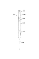
次に図2および図3において、上記工具100の本体部分110が比較的に詳細に示されている。この本体部分110は一定のステム部分124を有しており、このステム部分124は、図において示されているように、例えば、一定の長方形の断面を有している。このステム部分124は上記関節101における第1の部分112に対応している(図1を参照されたい)。この関節における第1の部分112はその大腿骨における遠位側ステム部分である。このステム部分124の一端部から本体部分110における拡大部分126が延出している。この拡大部分126は近位側大腿骨に対応している。さらに、一定のスロット130がこの本体部分110における拡大部分126の中に長手方向に沿って配置されている。
2 and 3, the
次に図4において、上記第1のセグメント部分114が比較的に詳細に示されている。この第1のセグメント部分114は第1のセグメント基部132を有している。
Referring now to FIG. 4, the
一定のカルカー(距部)スライド134が第1の中心線136に沿って第1のセグメント基部132から第1の方向に延在している。さらに、レール140が第1の中心線136に対して反対側の位置にカルカー・スライド134に沿ってそれぞれ延在している。これらのレール140は本体部分110のスロット130と共に協働する(図2を参照されたい)。
A
再び図4において、上記第1のセグメント基部132から外側に一定のオフセット・スライド142が延在している。このオフセット・スライド142は上記第1の中心線136に対して、例えば、約90度の一定の角度αにおける第2の中心線144に沿って延在している。さらに、上記レール140に類似しているレール146が第2の中心線144に対して垂直な方向にオフセット・スライド142から延出している。これらのレール146は上記第2のセグメント部分120におけるスロット150と共に協働する(図5を参照されたい)。
Referring again to FIG. 4, an offset
次に図5において、上記第2のセグメント部分120が比較的に詳細に示されている。この第2のセグメント部分120は一定の摺動部分152および当該摺動部分152から延出しているネック部分154を含む。さらに、摺動部分152は一定の摺動中心線156に沿って配置されているスロット150を含む。このスロット150は上記第1のセグメント部分114の中に第2のセグメント部分120を案内および拘束することのできる任意の形状を有することができるが、このスロット150がその摺動部分152の中に溝部164を形成している一定の近位側リップ部160および一定の遠位側リップ部162を含むことが可能であることが当然に認識されると考える。さらに、これらの溝部164は上記第1のセグメント部分114の各レール146に対して係合状態で嵌合するように寸法付けられている。
Referring now to FIG. 5, the
上記ネック部154は上記摺動中心線156に対して角度βにより定められている一定の方向におけるネック部中心線166に沿って延在している。この角度βは好ましくはこのプロテーゼのネック部の角度に相当している。
The
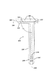
次に図6において、上記工具100は一定の長い骨または大腿骨101の上方に配置されている状態で示されている。従って、図6において示されているように、この工具100は骨の切除の開始の前、無菌パッケージからの工具の取り出しの前、および一定の試行および試行の整復の使用前に特定の移植片の適正を決定するために、手術中において利用可能であり、上記大腿骨101の上方に位置決め可能である。さらに、この工具100を大腿骨101の上方に位置決めして、その切除用の案内面部172を大腿骨101に対して配置することができる。この切除用の案内面部172に対する整合により一定の適正な切除面74が決定できる。
Referring now to FIG. 6, the
再び図1において、上記工具100は上記第1のセグメント部分114に対する上記本体部分110の相対位置の決定を補助するための指示手段176を含むことができる。この指示手段176は本体部分110における単独の標識178および第1のセグメント部分114における複数の第1セグメント標識180を含むことができる。第1のセグメント部分114が各矢印182および184の方向に本体部分110におけるスロット130に沿って摺動すると、第1セグメント標識180が本体部分標識178に対してそれぞれ整合する。例えば、図1において示されているように、これらの第1セグメント標識180はそれぞれの基準数字186により認識できる。さらに、これらの基準数字186は一定の相対的なまたは絶対的な距部の高さを示すことができ、あるいは、それぞれの第1セグメント標識180に対する本体部分標識178の整合により示される適当な距部の高さを有する特定のプロテーゼに対応できる。
Referring again to FIG. 1, the
上記の本体部分および第1のセグメント部分114は互いに選択可能に固定して取り付けることができる。例えば、この第1のセグメント部分114は一定のねじ192がねじを介して固定できる一定のねじ係合可能な穴または開口部190を有することができる。このねじ192は第1のセグメント部分114が本体部分110に対してその適正な位置に移動する際に選択的に締め付けることおよび緩めることができる。
The body portion and the
利用可能なプロテーゼの種々の距部の高さに相当する位置に上記第1のセグメント部分114を本体部分110に対して位置決めすることを補助するために、本体部分110は上記スロット130に対して中央に形成されている複数の凹部194を有することができ、これらの凹部194は、各矢印182および184の方向にスロット130に沿って適正な位置にある時に、所定の種々の距部の高さを伴って利用可能なプロテーゼに対応するように上記第1セグメント標識180を本体部分標識178に位置決めするために上記ねじ192に対して整合して操作可能に相互作用できる。このねじ192は凹部194と協働するための一定のばね負荷型のボール端部(図示されていない)を有することができる。
To assist in positioning the
さらに、上記第1のセグメント部分114および第2のセグメント部分120は当該第1のセグメント部分114の第2のセグメント部分120に対する相対位置を決定するための指示手段195を有することができる。この指示手段195は、上記指示手段176と同様に、上記第1のセグメント部分114に配置されている第1セグメント標識196および上記第2のセグメント部分120に配置されている複数の第2セグメント標識197を含むことができる。さらに、この指示手段195は上記第2セグメント標識197に付随している複数の基準数字198を含むことができる。これらの基準数字198は絶対的または相対的な意味におけるそれぞれのずれの位置を示すことができ、あるいは、特定の利用可能なプロテーゼを示すことができる。
Further, the
上記第2のセグメント部分120は、例えば、上記ねじ192と類似している一定のねじ183により上記第1のセグメント部分114に選択的に取り付け可能であり、このねじ183は第1のセグメント部分114における貫通穴181を通してねじ係合により固定できる。さらに、複数の凹部185を上記第2のセグメント部分120に形成することができ、これらの凹部185が上記ねじ183に対して整合する時に、上記第1セグメント標識196が幾つかの第2セグメント標識197の内の1個に対して整合可能になるように各凹部185が位置決めされる。
The
一定の大腿骨のX線写真画像または実際の大腿骨のいずれかに対する上記工具100の整合を補助するために、この工具100は、例えば、一定のプラスチック材料等のような一定の半透明または透明な材料により作成できる。
To assist in aligning the
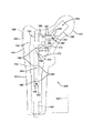
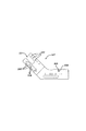
本発明によれば、図7において、本発明の別の実施形態が工具200として示されている。この工具200は、上記工具100と同様に、一定のX線写真102による一定の関節の画像104に関連して使用できる。この図7において示されている工具は左股関節に対する関節形成術において用いられる。図1の工具100と同様に、この工具200は任意の適当な耐久性の材料により作成可能であり、例えば、一定の金属またはプラスチック材により作成できる。さらに、上記工具100と同様に、この工具200は、例えば、図7において示されているように、図1の本体部分110に類似している一定の本体部分210を含む複数の部品により構成されている。さらに、図7において示されているように、本体部分210は一定のステム部分224ならびに一定の拡大部分226を有している。このステム部分224は大腿骨101の遠位側部分に整合し、拡大部分226は近位側の大腿骨に整合する。
According to the present invention, another embodiment of the present invention is shown in FIG. The
図1の工具100と同様に、上記工具200はさらにその本体部分210に対して摺動可能に固定されている第1のセグメント部分214を有している。この第1のセグメント部分214は各矢印282および284の方向に上記ステム部分224内において摺動可能に移動できる。上記工具200はさらに上記第1のセグメント部分214に対して摺動可能に移動できる第2のセグメント部分220を有している。上記工具100とは異なり、この工具200はさらに上記第2のセグメント部分220に対して摺動可能に移動できる第3のセグメント部分233を有している。この第3のセグメント部分233は大腿骨101の頭部201に対して整合する。
As with the
次に図8,9および11において、上記本体部分210が比較的に詳細に示されている。この本体部分210は遠位側ステム部224および拡大部分226を有している。図8において示されているように、この本体部分210は当該本体部分210を貫通している一定の開口部202を有している。この開口部202は第1のセグメント部分214が各矢印282および284の方向にそれぞれ上下動する際にこの第1のセグメント部分214を観察することを可能にしている。図1における工具100の本体部分110と同様に、この本体部分210は当該本体部分210の第1のセグメント部分214に対する相対位置の決定を補助するための指示手段276を有している。
8, 9 and 11, the
例えば、図11において示されているように、この指示手段276は上記第1のセグメント部分214において配置されている一定の標識278ならびに本体部分210における複数の線の形態における標識280を含む。これらの線280のそれぞれは対応するそれぞれの数字286を含むことができ、これにより、各数字286がそれぞれの線280の間の相対的な距離を示すことが可能になり、あるいは、上記工具200が適当であると示していると考えられる一定のプロテーゼに相当する状態を示すことができる。
For example, as shown in FIG. 11, the indicating means 276 includes a
再び図8において、上記第1のセグメント部分214は任意の適当な様式で各矢印282および284の方向に本体部分210に対して摺動可能に係合できる。例えば、本体部分210が一定のスロット230を有していて、第1のセグメント部分214が一定のカルカー(calcar)・スライド部分234を有することができる。このスライド部分234は上記スロット230の中に摺動可能に嵌合できる。
Referring again to FIG. 8, the
上記第1のセグメント部分214は、例えば、本体部分210に形成されている穴290において当該本体部分210にねじを介して係合可能である一定のねじ292により当該本体部分210に選択的に且つ除去可能に固定できる。このねじ292は上記第1のセグメント部分214に形成されている各凹部294に対して接触可能である一定のばね負荷型のボール形状の接触点(図示されていない)を有することができる。このねじ292の接触点は上記第1のセグメント部分214が各矢印282および284の方向に移動する際に各凹部294に対して接触して、特に一定の露出している大腿骨により配置される場合に、上記各数字286により各位置の場所を指示可能にして比較的に容易に位置決めできる。
The
次に図10において、一定の本体部分211が示されており、この本体部分211は上記本体部分210の一定の鏡像体であり、一定の右股関節形成術と共に使用可能である。なお、上記工具200の各部品に対する一定の鏡像体を形成するためにこの本体部分211と共に上記の第1のセグメント部分214、第2のセグメント部分220、および第3のセグメント部分233の各鏡像体が使用可能であることが当然に認識されると考える。
Referring now to FIG. 10, a
次に図12において、上記第1のセグメント部分214が比較的に詳細に示されている。この第1のセグメント部分214は図1の工具100における第1のセグメント部分114に類似している。この第1のセグメント部分214は一定の中央基部232を有している。さらに、この中央基部232から第1の中心線236に沿ってカルカー・スライド部分234が延在している。また、上記基部232から第1の中心線236に対して一定の角度ααで一定のオフセット・スライド部分242が延在しており、このスライド部分242は第2の中心線244に沿って延在している。
Referring now to FIG. 12, the
再び図8において、上記カルカー・スライド部分234はスロット230に沿って各矢印282および284の方向に摺動する。このカルカー・スライド部分は当該カルカー・スライド234から延出している各レール240により案内されて保持されている。一定の標識278が上記本体部分210に対する上記第1のセグメント部分214の相対位置の決定を補助するためにカルカー・スライド部分に配置されている。さらに、上記オフセット・スライド部分242が上記第2のセグメント部分220に対して摺動可能に係合していて、当該オフセット・スライド部分242から延出している各レール246により案内されている。
Referring again to FIG. 8, the
再び図8において、上記第2のセグメント部分220は上記オフセット・スライド部分242に沿って各矢印204の方向に摺動可能に移動できる。
Referring again to FIG. 8, the
次に図13,14および15において、上記第2のセグメント部分220が比較的に詳細に示されている。この第2のセグメント部分220は一定のネック部分254および一定の摺動部分252を有している。さらに、摺動部分252は上記第1のセグメント部分214におけるオフセット・スライド部分242と共に協働する一定のスロット250を有している。このスロット250は溝部264を形成している各リップ部260および262により定められており、これらの溝部264は上記オフセット・スライド部分242の各レール246に係合する(図8を参照されたい)。
13, 14, and 15, the
好ましくは、図12および図14において示されているように、上記工具200は上記第1のセグメント部分214に対する上記第2のセグメント部分220の相対位置を決定するための指示手段195を備えている。この指示手段195は、例えば、上記第1のセグメント部分214および第2のセグメント部分220の一方における複数の基準標識197および各セグメント部分214および220の他方における一定の単独標識の形態にすることができる。例えば、第2のセグメント部分220は複数の基準標識197を有することができ、第1のセグメント部分214は単一の基準標識278を有することができる。さらに、複数の基準数字298を上記の各基準標識197の近くに配置して第2のセグメント部分220の第1のセグメント部分214に対する相対的な位置決めを補助することができる。これらの基準数字298は上記基準標識の相対位置を示すことができ、あるいは、上記工具200が提示すると考えられる適当な移植片に相当する特定の寸法または数の整形外科移植片に対応できる。
Preferably, as shown in FIGS. 12 and 14, the
次に図12乃至図14において、上記第2のセグメント部分220は任意の適当な様式で上記第1のセグメント部分214に対して選択的に固定できる。例えば、この第2のセグメント部分220は当該第2のセグメント部分220を第1のセグメント部分214に対して選択的に且つ固定可能に固定するための一定の係止用の特徴部分を有することができる。例えば、上記摺動部分252は上記スロット250の中に通されている一定のねじ付きの穴206を有することができる。さらに、一定のねじ208がこのねじ付きの穴206にねじ係合により固定できる。なお、このねじ208は上記本体部分210において用いられているねじ292に類似していると考えられる。また、このねじ208は一定のばね負荷型のボール先端部分を有することができる。さらに、上記第1のセグメント部分214におけるオフセット・スライド部分242は上記の各基準数字298に対する係合において所定の位置を与える複数の凹部209を有することができる。
12-14, the
再び図8において、上記第3のセグメント部分233は第2のセグメント部分220に摺動可能に接続していて、矢印217の方向に移動可能である。
Referring again to FIG. 8, the
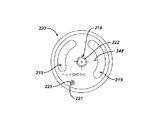
次に図14,15,16および17において、上記第3のセグメント部分233が比較的に詳細に示されている。この第3のセグメント部分233は概ね円筒形の形状を有しており、図16において示されているように、1個の中央穴218ならびに2個の弓形の開口部219を有している。この第3のセグメント部分233は一定の適当な様式で上記第2のセグメント部分220のネック部分254に摺動可能に固定できる。例えば、一定のピン219をこの第3のセグメント部分233における穴218に嵌合状態で固定することができる。さらに、このピン219は上記第2のセグメント部分220のネック部分254の中における開口部221に摺動可能に嵌合できる。
14, 15, 16 and 17, the
あるいは、または、さらに、上記ピン219の使用に対して、上記第3のセグメント部分233は上記ネック部分254が摺動可能に嵌合できる一定の中央スロット223を有することも可能である。
Alternatively or additionally, for use of the
上記第3のセグメント部分233は任意の適当な様式で上記第2のセグメント部分220に選択的に且つ固定可能に取り付けることができる。例えば、この第3のセグメント部分233はねじ227をねじ係合可能に取り付けることのできる一定のねじ付き穴225を有することができる。このねじ227は上記のねじ208と類似していると考えられ、一定のばね負荷型の球形の先端部分を有することができる。所定の位置に供給するために、上記第2の部材220は所定の各位置に供給するためにねじ227に対して整合可能な複数の凹部228を有することができる。これらの所定の位置は参照数字243に対して整合できる。
The
図14乃至図16において、上記第2のセグメント部分220におけるネック部分254は上記摺動部分252における摺動中心線231に対して一定の角度ββで延在している一定のネック部中心線229に沿って上記第2のセグメント部分220の摺動部分252から延出できる。
14 to 16, a
上記第2のセグメント部分220に対する上記第3のセグメント部分233の位置の観察を補助するために、上記第2のセグメント部分220および/または第3のセグメント部分233は当該第3のセグメント部分233の第2のセグメント部分220に対する相対位置を決定するための指示手段241を備えることができる。例えば、この指示手段241は上記第2のセグメント部分220のネック部分254における複数の標識245および上記第3のセグメント部分233に配置されている一定の単独標識248の形態にすることができる。加えて、この指示手段241は複数の基準数字243を含むことができ、これらの数字は各標識245に対して整合状態で配置可能であり、隣接しているそれぞれの標識245の間の特定の離間距離に対応することができ、あるいは、上記工具200において決定された特定の設定に対応する提示された移植片に対応できる。
To assist in observing the position of the
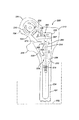
次に図18および図19において、本発明の別の実施形態が工具300として示されている。この工具300は図7乃至図17における工具200に類似しているが、当該工具200における第3のセグメント部分233の代わりに、この工具300は一定の概ねテーパー状の形状を有していて一定のプロテーゼ・ステム部分におけるネック部のテーパー形状に対応している第3のセグメント部分333を有している。なお、この工具300がさらに上記工具200の第2のセグメント部分220における指示手段195に類似している指示手段341を有し得ることが当然に認識されると考える。
18 and 19, another embodiment of the present invention is shown as a
次に図20において、一定の2個部材片型のプロテーゼ400が上記工具100に関連する使用方法において示されている。このプロテーゼ400は一定の近位側本体部分410および一定の遠位側ステム部分412を有している。なお、この近位側本体部分410は種々のずれの長さOFおよびネック部の長さNLを含む多様な形状を有し得ることが当然に認識されると考える。同様に、遠位側ステム部分412は種々のステム部の長さSLを含む多様な寸法を有することができる。
Referring now to FIG. 20, a two piece prosthesis 400 is shown in use in conjunction with the
次に図21において、一定のモノリシック型のプロテーゼ450が示されている。この場合においても、このプロテーゼが種々の横方向のずれLOF、ネック部の長さNLSおよびステム部の長さSLHを有する多様な形状を有し得ることが当然に認識されると考える。
Referring now to FIG. 21, a
次に図22において、上記プロテーゼ400と共に使用するための種々の近位側本体部分および遠位側本体部分が示されている。これらの近位側本体部分は一定のサイズ6の近位側本体部分420、サイズ8の近位側本体部分422、およびサイズ10の近位側本体部分424を含む。さらに、これらの近位側本体部分は一定のサイズ40の近位側本体部分430、サイズ21の近位側本体部分432、およびサイズ0の近位側本体部分434も含む。なお、短いステム部450、中程度の長さのステム部452および長いステム部454における好ましい遠位側ステム部が、例えば、これら3種類の可能なステム部の内の1個にそれぞれ対応している指示手段(図示されていない)を有する上記基部110から延出可能な一定の摺動アーム199(仮想線で示されている)を使用することにより本発明のテンプレート100(図1を参照されたい)の使用と共に選択可能になることが当然に認識されると考えられる。
Referring now to FIG. 22, various proximal and distal body portions for use with the prosthesis 400 are shown. These proximal body portions include a
次に図1および図22において、上記工具100における各基準数字186が各近位側本体部分430,432および434にそれぞれ対応している。それゆえ、図1において示されているように、適当な距部の高さが一定のサイズ0である場合、すなわち、上記基準数字186が上記本体部分標識178に整合している場合に、その適当な近位側本体部分は上記の近位側本体部分434である。
Next, in FIGS. 1 and 22, each
同様に、図1および図22において、適当なずれが一定のサイズ8である場合、すなわち、上記第2のセグメント部分120における基準数字198が上記第1セグメント標識196に整合している場合に、この基準数字8は上記の近位側本体部分422の選択に対応している。
Similarly, in FIGS. 1 and 22, if the appropriate offset is a
次に図23および図24において、一定の多数個部材片型のプロテーゼ股関節大腿部品500が示されている。この大腿部品500は一定の近位側本体部分504に接続している一定の遠位側ステム部502を有している。さらに、一定のヘッド部506が近位側本体部分504に接続している。また、一定のスリーブ508が近位側本体部分504の上に嵌合している。さらに、一定のナット509が上記の近位側本体部分を遠位側ステム部502に固定するために用いられている。
23 and 24, a multi-piece prosthesis hip
次に図25,26および27において、上記図7乃至図17における工具200に関連して使用するための複数の遠位側ステム部、近位側本体部分、およびヘッド部がそれぞれ示されている。例えば、図7および図25において、一定の近位側本体部分が上記工具200における第2のセグメント部分220による適正なずれを設定して適正な数字298を観察することにより適正なずれを伴って選択できる。この適正な数字298を参考にすることにより、これに対応する適当な近位側本体部分が選択できる。例えば、ずれがゼロ(0)の場合に、近位側本体部分520が選択され、ずれがサイズ6である場合に、近位側本体部分522が選択され、ずれがサイズ8である場合に、近位側本体部分524が選択され、ずれがサイズ12である場合に近位側本体部分526が選択されることになる。なお、短いステム部650、中程度の長さのステム部652および長いステム部654の内の好ましい遠位側ステム部が、例えば、これら3種類の可能なステム部の内の1個にそれぞれ対応している指示手段(図示されていない)を有する上記基部110から延出可能な一定の摺動アーム199(仮想線で示されている)を使用することにより本発明のテンプレート100(図1を参照されたい)の使用と共に選択可能になることが当然に認識されると考えられる。
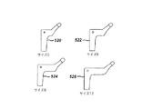
Referring now to FIGS. 25, 26 and 27, a plurality of distal stem portions, proximal body portions, and head portions, respectively, for use in connection with
次に図7および図26において、適当な近位側本体部分が当該本体部分に関する基準数字286により観察される上記工具200によるカルカー・サイズ(距部の高さ)の指示を調べることにより選択可能になる。例えば、基準数字40の場合に、近位側本体部分630が選択される。また、カルカー・サイズ(基準数字)が21の場合には、近位側本体部分632が選択され、カルカー・サイズが0の場合には近位側本体部分634が選択されることになる。
7 and 26, the appropriate proximal body portion can be selected by examining the Kalkar size (distance height) indication by the
次に図27および図14において、適当なヘッド部が図14において示されているような指示手段241により選択される各基準数字243に基いて選択可能になる。例えば、ヘッド部中心の数字6の場合に、ヘッド部640が選択され、ヘッド部中心12の場合に、ヘッド部642が選択され、ヘッド部中心0の場合に、ヘッド部644が選択され、ヘッド部中心3の場合に、ヘッド部646が選択され、ヘッド部中心9の場合にはヘッド部648が選択されることになる。
Next, in FIGS. 27 and 14, an appropriate head unit can be selected based on each
次に図28において、関節形成術において使用するための複数のプロテーゼ部品の内の1個を選択するための一定の方法700が示されている。この方法700は一定の患者の骨の解剖学的構造における一定のX線写真画像を得る第1の工程702を含む。また、この方法700は上記X線写真画像における第1の部分に整合するための第1の部分および当該X線写真画像における第2の部分に整合するための第2の部分を有する一定の工具を供給する第2の工程704を含み、当該工具の第1部分がこの工具の第2の部分に対して移動可能であり、この工具が上記X線写真画像における少なくとも1個の寸法を測定するために用いられる。さらに、上記方法700は上記X線写真画像の第1の部分に対して上記工具の第1の部分を整合する第3の工程を含む。また、この方法700は上記X線写真画像の第2の部分に対して上記工具の第2の部分を整合する第4の工程708を含む。さらに、上記方法700は上記X線写真画像における少なくとも1個の寸法を測定するために上記工具を使用する第5の工程710、および上記の測定した寸法に基いて上記複数のプロテーゼ部品の内の1個を選択する第6の工程712を含む。
Referring now to FIG. 28, a
次に図29において、関節形成術において使用するための複数のプロテーゼ部品の内の1個を選択するための一定の方法800が示されている。この方法800は一定の患者の骨の解剖学的構造における第1の部分に整合するための第1の部分および当該骨の解剖学的構造における第2の部分に整合するための第2の部分を有する一定の工具を供給する第1の工程802を含み、当該工具の第1の部分がこの工具の第2の部分に対して移動可能であり、この工具が上記骨の解剖学的構造における少なくとも1個の寸法を測定するために用いられる。また、上記方法800は上記工具の第1の部分を上記骨の解剖学的構造における第1の部分に整合する第2の工程804を含む。さらに、この方法800は上記工具の第2の部分を上記骨の解剖学的構造における第2の部分に整合する第3の工程806を含む。また、上記方法800は上記骨の解剖学的構造における少なくとも1個の寸法を測定するために上記工具を使用する第4の工程808、および上記の測定した寸法に基いて上記複数のプロテーゼ部品の内の1個を選択する第5の工程810を含む。
Referring now to FIG. 29, a
以上において、本発明およびその種々の利点を詳細に説明したが、種々の変形、置換および変更が添付の特許請求の範囲により定められている本発明の趣旨および範囲から逸脱することなく上記の説明において行なえることが当然に理解されると考える。 While the invention and its various advantages have been described in detail above, various modifications, substitutions and changes may be made without departing from the spirit and scope of the invention as defined by the appended claims. It is understood that what can be done in is understood.
本発明は従来に増して付加的な機能性を伴う一定のプロテーゼ移植片およびこれに関連の方法に適用可能である。この装置はその使用者が横方向のずれをテンプレート処理するために一定の中央から横の方向にそのネック部分を摺動することを可能にしている一定の調節可能な装置である。この装置はまたそのテンプレートの足部の長さまで一定の近位側から遠位側の方向に摺動可能である。随意的に、この器具はそのネック部の長さまたはヘッド部の長さまたはこれらの組み合わせのいずれかをテンプレート処理するために一定の斜めの方向に摺動できる。さらに、実際の横方向のずれ、足部の長さおよびネック部の長さがそれぞれの量を示すために、さらに移植片の選択を補助する目的のためにその器具の一定の部分にエッチングすることが可能である。 The present invention is applicable to certain prosthetic implants with additional functionality and related methods. The device is an adjustable device that allows the user to slide the neck in a lateral direction from a center to template the lateral offset. The device is also slidable in a constant proximal to distal direction up to the length of the template foot. Optionally, the instrument can slide in an oblique direction to template either the length of its neck or the length of the head or a combination thereof. In addition, a certain portion of the device is etched to indicate the actual lateral shift, foot length and neck length, respectively, and to aid in the selection of the implant. It is possible.
本発明の具体的な実施態様は以下のとおりである。
(1)さらに、第2のセグメント部分を備えており、当該第2のセグメント部分が前記本体部分および前記第1のセグメント部分の内の1個に対して移動可能であり、当該第2のセグメント部分が前記解剖学的な関節における第3の部分に整合するための部分である請求項1に記載の工具。
(2)さらに、第3のセグメント部分を備えており、当該第3のセグメント部分が前記本体部分、前記第1のセグメント部分および前記第2のセグメント部分の内の1個に対して移動可能であり、当該第3のセグメント部分が前記解剖学的な関節における第4の部分に整合するための部分である実施態様(1)に記載の工具。
(3)前記本体部分がその内部に一定の通路を定めており、前記第1のセグメント部分が当該通路の中において案内可能である実施態様(1)に記載の工具。
(4)前記本体部分および前記第1のセグメント部分の内の少なくとも1個が前記本体部分の前記第1のセグメント部分に対する相対位置を決定する指示手段をその上部に有している請求項1に記載の工具。
(5)前記本体部分および前記第1のセグメント部分の内の少なくとも1個が半透明である一定の部分を含んでいる請求項1に記載の工具。
Specific embodiments of the present invention are as follows.
(1) a second segment portion, wherein the second segment portion is movable with respect to one of the main body portion and the first segment portion; The tool of claim 1, wherein the portion is a portion for aligning with a third portion of the anatomical joint.
(2) Further, a third segment portion is provided, and the third segment portion is movable with respect to one of the main body portion, the first segment portion, and the second segment portion. The tool of claim 1, wherein the third segment portion is a portion for aligning with a fourth portion of the anatomical joint.
The tool of claim 1, wherein the body portion defines a passage therein, and wherein the first segment portion is guideable within the passage.
(4) At least one of the main body portion and the first segment portion has an indicator at an upper portion thereof for determining a relative position of the main body portion with respect to the first segment portion. The described tool.
5. The tool of claim 1, wherein at least one of the body portion and the first segment portion includes a portion that is translucent.
(6)前記本体部分および前記第1のセグメント部分の内の少なくとも1個が互いに選択的に且つ固定して取り付け可能である請求項1に記載の工具。
(7)前記画像が一定の解剖学的な関節のX線写真画像である請求項1に記載の工具。
(8)前記本体部分が一定の本体部分指示手段をその上部に有しており、さらに
前記第1のセグメント部分が複数のセグメント部分指示手段をその上部に有していて、当該セグメント部分指示手段の内の少なくとも一部分がプロテーゼ移植片における一定の推奨される寸法に対応している請求項1に記載の工具。
(9)前記プロテーゼ移植片における推奨される寸法が距部の高さ、ずれ、およびネック部の長さの内の1個である実施態様(9)に記載の工具。
(10)前記特定の種々の寸法の内の1個が距部の高さである請求項2に記載の工具。
6. The tool of claim 1, wherein at least one of the body portion and the first segment portion are selectively and fixedly attachable to one another.
(7) The tool according to claim 1, wherein the image is an X-ray image of an anatomical joint.
(8) The main body portion has a fixed main body portion indicating means on an upper portion thereof, and the first segment portion has a plurality of segment portion indicating means on an upper portion thereof, and the segment portion indicating means is provided. The tool of claim 1 wherein at least a portion of the tool corresponds to certain recommended dimensions of the prosthesis implant.
(9) The tool of embodiment (9), wherein the recommended dimensions of the prosthesis implant are one of a taller height, a displacement, and a neck length.
(10) The tool according to claim 2, wherein one of the specified various dimensions is a height of a distant portion.
(11)さらに、
第2のセグメント部分を備えており、当該第2のセグメント部分が前記第1のセグメント部分に対して移動可能であり、当該第1のセグメント部分が距部の高さを測定することにおいて使用するための部分であり、前記第2のセグメント部分がずれを測定することにおいて使用するための部分である請求項2に記載の工具。
(12)さらに、第3のセグメント部分を備えており、当該第3のセグメント部分が前記第2のセグメント部分に対して移動可能であり、当該第3のセグメント部分がネック部の長さを測定することにおいて使用するための部分である実施態様(11)に記載の工具。
(13)前記本体部分および前記第1のセグメント部分の内の少なくとも1個が前記特定の種々の寸法の内の少なくとも1個を測定するための指示手段をその上部に有している請求項2に記載の工具。
(14)前記本体部分および前記第1のセグメント部分の内の少なくとも1個が半透明な一定の部分を含んでいる請求項2に記載の工具。
(15)前記本体部分および前記第1のセグメント部分の内の少なくとも1個が互いに選択可能に固定して取り付け可能である請求項2に記載の工具。
(16)前記本体部分が一定の本体部分指示手段をその上部に有しており、さらに
前記第1のセグメント部分が複数のセグメント部分指示手段をその上部に有していて、当該セグメント部分指示手段の内の少なくとも一部分がプロテーゼ移植片における一定の推奨される寸法に対応している請求項2に記載の工具。
(11)
A second segment portion, the second segment portion being movable with respect to the first segment portion, wherein the first segment portion is used in measuring a height of a distance. 3. The tool of claim 2, wherein the second segment portion is a portion for use in measuring misalignment.
(12) Further, a third segment portion is provided, the third segment portion is movable with respect to the second segment portion, and the third segment portion measures a length of the neck portion. The tool of embodiment (11), which is a part for use in doing.
(13) At least one of the main body portion and the first segment portion has an indicator means thereon for measuring at least one of the specified various dimensions. Tools described in.
14. The tool of claim 2, wherein at least one of the body portion and the first segment portion includes a translucent portion.
(15) The tool according to claim 2, wherein at least one of the body portion and the first segment portion is selectably fixedly attachable to each other.
(16) The main body portion has a fixed main body portion indicating means on an upper portion thereof, and the first segment portion has a plurality of segment portion indicating means on an upper portion thereof, and the segment portion indicating means is provided. 3. The tool of claim 2, wherein at least a portion of the tools correspond to certain recommended dimensions of the prosthesis implant.
本発明および本発明の利点のさらに完全な理解のために、以下の添付図面に関連している説明が参照されている。
100 工具
101 解剖構造学的関節
102 X線写真プレート
104 X線写真画像
110 本体部分
112 第1の部分
114 セグメント部分
116 第2の部分
120 第2のセグメント部分
122 第3の部分
124 ステム部
130 スロット
132 第1セグメント基部
134 カルカー・スライド
140 レール
142 オフセット・スライド
146 レール
150 スロット
152 摺動部分
154 ネック部分
160 近位側リップ部
162 遠位側リップ部
164 溝部
176 指示手段
400 移植片
REFERENCE SIGNS
Claims (4)
前記解剖学的な関節における第1の部分に対して整合するための一定の本体部分、および
一定のセグメント部分を備えており、当該セグメント部分が前記本体部分に対して移動可能であり、当該セグメント部分が前記解剖学的な関節における第2の部分に対して整合するための部分であり、前記本体部分およびセグメント部分が一定の適当に寸法付けられている移植片の選択において使用するために前記解剖学的な関節における第1および第2の各部分の相対位置を測定するために適合している工具。 A tool for assisting in selecting an appropriately sized implant for use in performing arthroplasty, the tool comprising an anatomical joint and an anatomical joint A tool for cooperating with at least one of the images of the above, further comprising a body portion for alignment with a first portion of the anatomical joint, and a segment portion. The segment portion is movable with respect to the body portion, the segment portion is a portion for alignment with a second portion in the anatomical joint, and the body portion and the segment portion are aligned with each other. Measuring the relative position of the first and second portions in the anatomical joint for use in selecting a suitably sized implant A tool that conforms to.
前記解剖学的な関節における第1の部分に対して整合するための一定の本体部分、および
一定のセグメント部分を備えており、当該セグメント部分が前記本体部分に対して移動可能であり、当該セグメント部分が前記解剖学的な関節における第2の部分に対して整合するための部分であり、前記本体部分が前記第1の部分に対して整合していて前記セグメント部分が前記第2の部分に整合している時に、前記工具が前記特定の種々の寸法の内の1個を測定するために用いられる工具。 Use in measuring at least one of a variety of specific dimensions to assist in selecting an appropriate one of a plurality of femoral components in a hip implant for use in performing hip arthroplasty A tool for cooperating with at least one of an anatomical joint and a radiographic image of the anatomical joint; A body portion for alignment with a first portion of the natural joint, and a segment portion, wherein the segment portion is movable relative to the body portion and the segment portion is The body portion is aligned with the first portion and the segment portion is aligned with the second portion of the joint. When you are in alignment with the portion of the tool used for the tool to measure one of the particular variety of sizes.
一定の患者の骨の解剖学的構造における一定のX線写真画像を得る工程、
前記X線写真画像における第1の部分に整合するための第1の部分および当該X線写真画像における第2の部分に整合するための第2の部分を有する一定の工具を供給する工程を含み、前記工具の第1部分が当該工具の第2の部分に対して移動可能であり、当該工具が前記X線写真画像における少なくとも1個の寸法を測定するために用いられる工具であり、さらに、
前記X線写真画像の第1の部分に対して前記工具の第1の部分を整合する工程、
前記X線写真画像の第2の部分に対して前記工具の第2の部分を整合する工程、
前記X線写真画像における少なくとも1個の寸法を測定するために前記工具を用いる工程、および
前記測定した寸法に基いて前記複数のプロテーゼ部品の内の1個を選択する工程を含む方法。 A method for selecting one of a plurality of prosthetic components for use in arthroplasty, comprising:
Obtaining an x-ray image of the bone anatomy of the patient;
Providing a tool having a first portion for aligning a first portion in the radiographic image and a second portion for aligning a second portion in the radiographic image. A first portion of the tool is movable with respect to a second portion of the tool, wherein the tool is a tool used to measure at least one dimension in the radiographic image;
Aligning a first portion of the tool with a first portion of the radiographic image;
Aligning a second portion of the tool with a second portion of the radiographic image;
Using the tool to measure at least one dimension in the radiographic image; and selecting one of the plurality of prosthesis components based on the measured dimension.
一定の患者の骨の解剖学的構造における第1の部分に整合するための第1の部分および当該骨の解剖学的構造における第2の部分に整合するための第2の部分を有する一定の工具を供給する工程を含み、当該工具の第1の部分がこの工具の第2の部分に対して移動可能であり、当該工具が前記骨の解剖学的構造における少なくとも1個の寸法を測定するために用いられる工具であり、さらに
前記工具の第1の部分を前記骨の解剖学的構造における第1の部分に整合する工程、
前記工具の第2の部分を前記骨の解剖学的構造における第2の部分に整合する工程、
前記骨の解剖学的構造における少なくとも1個の寸法を測定するために前記工具を用いる工程、および
前記測定した寸法に基いて前記複数のプロテーゼ部品の内の1個を選択する工程を含む方法。 A method for selecting one of a plurality of prosthetic components for use in arthroplasty, comprising:
A first portion for matching a first portion of a bone anatomy of the patient and a second portion for matching a second portion of the bone anatomy; Providing a tool, wherein a first portion of the tool is movable relative to a second portion of the tool, the tool measuring at least one dimension in the anatomy of the bone. Aligning a first portion of the tool with a first portion in the anatomy of the bone;
Aligning a second portion of the tool with a second portion of the bone anatomy;
Using the tool to measure at least one dimension in the bone anatomy; and selecting one of the plurality of prosthesis components based on the measured dimension.
Applications Claiming Priority (1)
| Application Number | Priority Date | Filing Date | Title |
|---|---|---|---|
| US10/327,187 US20040122439A1 (en) | 2002-12-20 | 2002-12-20 | Adjustable biomechanical templating & resection instrument and associated method |
Publications (1)
| Publication Number | Publication Date |
|---|---|
| JP2004202230A true JP2004202230A (en) | 2004-07-22 |
Family
ID=32393138
Family Applications (1)
| Application Number | Title | Priority Date | Filing Date |
|---|---|---|---|
| JP2003422835A Abandoned JP2004202230A (en) | 2002-12-20 | 2003-12-19 | Equipment for bio-mechanical template treatment capable of controlling and for resection, and related method |
Country Status (6)
| Country | Link |
|---|---|
| US (1) | US20040122439A1 (en) |
| EP (1) | EP1430859B1 (en) |
| JP (1) | JP2004202230A (en) |
| AT (1) | ATE343990T1 (en) |
| AU (1) | AU2003268842B2 (en) |
| DE (1) | DE60309419T2 (en) |
Cited By (1)
| Publication number | Priority date | Publication date | Assignee | Title |
|---|---|---|---|---|
| JP2021528195A (en) * | 2018-06-26 | 2021-10-21 | デピュイ・アイルランド・アンリミテッド・カンパニーDepuy Ireland Unlimited Company | Femoral neck resection guide |
Families Citing this family (101)
| Publication number | Priority date | Publication date | Assignee | Title |
|---|---|---|---|---|
| US20040267267A1 (en) | 2003-06-25 | 2004-12-30 | Daniels David Wayne | Non-linear reamer for bone preparation and associated method |
| US7297166B2 (en) | 2003-06-25 | 2007-11-20 | Depuy Products, Inc. | Assembly tool for modular implants and associated method |
| US8998919B2 (en) | 2003-06-25 | 2015-04-07 | DePuy Synthes Products, LLC | Assembly tool for modular implants, kit and associated method |
| US7582092B2 (en) | 2003-06-25 | 2009-09-01 | Depuy Products, Inc. | Assembly tool for modular implants and associated method |
| US7967868B2 (en) | 2007-04-17 | 2011-06-28 | Biomet Manufacturing Corp. | Patient-modified implant and associated method |
| US9289253B2 (en) | 2006-02-27 | 2016-03-22 | Biomet Manufacturing, Llc | Patient-specific shoulder guide |
| US9907659B2 (en) | 2007-04-17 | 2018-03-06 | Biomet Manufacturing, Llc | Method and apparatus for manufacturing an implant |
| US8608748B2 (en) | 2006-02-27 | 2013-12-17 | Biomet Manufacturing, Llc | Patient specific guides |
| US8377066B2 (en) | 2006-02-27 | 2013-02-19 | Biomet Manufacturing Corp. | Patient-specific elbow guides and associated methods |
| US10278711B2 (en) | 2006-02-27 | 2019-05-07 | Biomet Manufacturing, Llc | Patient-specific femoral guide |
| US9918740B2 (en) | 2006-02-27 | 2018-03-20 | Biomet Manufacturing, Llc | Backup surgical instrument system and method |
| US8070752B2 (en) | 2006-02-27 | 2011-12-06 | Biomet Manufacturing Corp. | Patient specific alignment guide and inter-operative adjustment |
| US8473305B2 (en) | 2007-04-17 | 2013-06-25 | Biomet Manufacturing Corp. | Method and apparatus for manufacturing an implant |
| US8407067B2 (en) | 2007-04-17 | 2013-03-26 | Biomet Manufacturing Corp. | Method and apparatus for manufacturing an implant |
| US8535387B2 (en) | 2006-02-27 | 2013-09-17 | Biomet Manufacturing, Llc | Patient-specific tools and implants |
| US8241293B2 (en) | 2006-02-27 | 2012-08-14 | Biomet Manufacturing Corp. | Patient specific high tibia osteotomy |
| US9339278B2 (en) | 2006-02-27 | 2016-05-17 | Biomet Manufacturing, Llc | Patient-specific acetabular guides and associated instruments |
| US8864769B2 (en) | 2006-02-27 | 2014-10-21 | Biomet Manufacturing, Llc | Alignment guides with patient-specific anchoring elements |
| US8092465B2 (en) | 2006-06-09 | 2012-01-10 | Biomet Manufacturing Corp. | Patient specific knee alignment guide and associated method |
| US8282646B2 (en) | 2006-02-27 | 2012-10-09 | Biomet Manufacturing Corp. | Patient specific knee alignment guide and associated method |
| US8591516B2 (en) | 2006-02-27 | 2013-11-26 | Biomet Manufacturing, Llc | Patient-specific orthopedic instruments |
| US8568487B2 (en) | 2006-02-27 | 2013-10-29 | Biomet Manufacturing, Llc | Patient-specific hip joint devices |
| US9113971B2 (en) | 2006-02-27 | 2015-08-25 | Biomet Manufacturing, Llc | Femoral acetabular impingement guide |
| US8133234B2 (en) | 2006-02-27 | 2012-03-13 | Biomet Manufacturing Corp. | Patient specific acetabular guide and method |
| US20150335438A1 (en) | 2006-02-27 | 2015-11-26 | Biomet Manufacturing, Llc. | Patient-specific augments |
| US9173661B2 (en) | 2006-02-27 | 2015-11-03 | Biomet Manufacturing, Llc | Patient specific alignment guide with cutting surface and laser indicator |
| US8608749B2 (en) | 2006-02-27 | 2013-12-17 | Biomet Manufacturing, Llc | Patient-specific acetabular guides and associated instruments |
| US8603180B2 (en) | 2006-02-27 | 2013-12-10 | Biomet Manufacturing, Llc | Patient-specific acetabular alignment guides |
| US8858561B2 (en) | 2006-06-09 | 2014-10-14 | Blomet Manufacturing, LLC | Patient-specific alignment guide |
| US8298237B2 (en) | 2006-06-09 | 2012-10-30 | Biomet Manufacturing Corp. | Patient-specific alignment guide for multiple incisions |
| US9345548B2 (en) | 2006-02-27 | 2016-05-24 | Biomet Manufacturing, Llc | Patient-specific pre-operative planning |
| US9795399B2 (en) | 2006-06-09 | 2017-10-24 | Biomet Manufacturing, Llc | Patient-specific knee alignment guide and associated method |
| US8597298B2 (en) | 2006-09-29 | 2013-12-03 | DePuy Synthes Products, LLC | Proximal reamer |
| WO2008132424A1 (en) * | 2007-04-28 | 2008-11-06 | Depuy International Limited | Determining the offset of the head part of an orthopaedic joint prosthesis stem component |
| US8265949B2 (en) | 2007-09-27 | 2012-09-11 | Depuy Products, Inc. | Customized patient surgical plan |
| US8357111B2 (en) | 2007-09-30 | 2013-01-22 | Depuy Products, Inc. | Method and system for designing patient-specific orthopaedic surgical instruments |
| ES2802126T3 (en) | 2007-09-30 | 2021-01-15 | Depuy Products Inc | Patient Specific Custom Orthopedic Surgical Instrument |
| US8556912B2 (en) | 2007-10-30 | 2013-10-15 | DePuy Synthes Products, LLC | Taper disengagement tool |
| US8518050B2 (en) | 2007-10-31 | 2013-08-27 | DePuy Synthes Products, LLC | Modular taper assembly device |
| JP5535944B2 (en) | 2008-02-25 | 2014-07-02 | スミス アンド ネフュー インコーポレーテッド | Method and system for mapping a femoral head for registration of an artificial acetabulum |
| US9271848B2 (en) * | 2008-10-24 | 2016-03-01 | The Cleveland Clinic Foundation | Prosthetic joint component planning template |
| WO2010051457A1 (en) * | 2008-10-31 | 2010-05-06 | Zimmer, Inc. | Expandable arthroplasty plates |
| US8170641B2 (en) | 2009-02-20 | 2012-05-01 | Biomet Manufacturing Corp. | Method of imaging an extremity of a patient |
| DE102009028503B4 (en) | 2009-08-13 | 2013-11-14 | Biomet Manufacturing Corp. | Resection template for the resection of bones, method for producing such a resection template and operation set for performing knee joint surgery |
| US8632547B2 (en) | 2010-02-26 | 2014-01-21 | Biomet Sports Medicine, Llc | Patient-specific osteotomy devices and methods |
| US9066727B2 (en) | 2010-03-04 | 2015-06-30 | Materialise Nv | Patient-specific computed tomography guides |
| US8419743B2 (en) * | 2010-03-05 | 2013-04-16 | Biomet Manufacturing Corp. | Assembly tool for modular implants and associated method |
| US8460393B2 (en) | 2010-03-05 | 2013-06-11 | Biomet Manufacturing Corp. | Modular lateral hip augments |
| US8333807B2 (en) | 2010-03-05 | 2012-12-18 | Biomet Manufacturing Corp. | Method and apparatus for trialing and implanting a modular femoral hip |
| US8221432B2 (en) | 2010-03-05 | 2012-07-17 | Biomet Manufacturing Corp. | Method and apparatus for implanting a modular femoral hip |
| US8679130B2 (en) * | 2010-03-05 | 2014-03-25 | Biomet Manufacturing, Llc | Guide assembly for lateral implants and associated methods |
| US8529569B2 (en) | 2010-03-05 | 2013-09-10 | Biomet Manufacturing, Llc | Method and apparatus for preparing a proximal femur |
| US8533921B2 (en) | 2010-06-15 | 2013-09-17 | DePuy Synthes Products, LLC | Spiral assembly tool |
| US9095452B2 (en) | 2010-09-01 | 2015-08-04 | DePuy Synthes Products, Inc. | Disassembly tool |
| US9271744B2 (en) | 2010-09-29 | 2016-03-01 | Biomet Manufacturing, Llc | Patient-specific guide for partial acetabular socket replacement |
| US9968376B2 (en) | 2010-11-29 | 2018-05-15 | Biomet Manufacturing, Llc | Patient-specific orthopedic instruments |
| US9241745B2 (en) | 2011-03-07 | 2016-01-26 | Biomet Manufacturing, Llc | Patient-specific femoral version guide |
| US20120259339A1 (en) | 2011-04-06 | 2012-10-11 | Hood Megan A | Instrument assembly for implanting a revision hip prosthesis and orthopaedic surgical procedure for using the same |
| US8715289B2 (en) | 2011-04-15 | 2014-05-06 | Biomet Manufacturing, Llc | Patient-specific numerically controlled instrument |
| US9675400B2 (en) | 2011-04-19 | 2017-06-13 | Biomet Manufacturing, Llc | Patient-specific fracture fixation instrumentation and method |
| US8956364B2 (en) | 2011-04-29 | 2015-02-17 | Biomet Manufacturing, Llc | Patient-specific partial knee guides and other instruments |
| US8668700B2 (en) | 2011-04-29 | 2014-03-11 | Biomet Manufacturing, Llc | Patient-specific convertible guides |
| US8532807B2 (en) | 2011-06-06 | 2013-09-10 | Biomet Manufacturing, Llc | Pre-operative planning and manufacturing method for orthopedic procedure |
| US9084618B2 (en) | 2011-06-13 | 2015-07-21 | Biomet Manufacturing, Llc | Drill guides for confirming alignment of patient-specific alignment guides |
| US20130001121A1 (en) | 2011-07-01 | 2013-01-03 | Biomet Manufacturing Corp. | Backup kit for a patient-specific arthroplasty kit assembly |
| US8764760B2 (en) | 2011-07-01 | 2014-07-01 | Biomet Manufacturing, Llc | Patient-specific bone-cutting guidance instruments and methods |
| US8597365B2 (en) | 2011-08-04 | 2013-12-03 | Biomet Manufacturing, Llc | Patient-specific pelvic implants for acetabular reconstruction |
| US9295497B2 (en) | 2011-08-31 | 2016-03-29 | Biomet Manufacturing, Llc | Patient-specific sacroiliac and pedicle guides |
| US9066734B2 (en) | 2011-08-31 | 2015-06-30 | Biomet Manufacturing, Llc | Patient-specific sacroiliac guides and associated methods |
| US9386993B2 (en) | 2011-09-29 | 2016-07-12 | Biomet Manufacturing, Llc | Patient-specific femoroacetabular impingement instruments and methods |
| US9301812B2 (en) | 2011-10-27 | 2016-04-05 | Biomet Manufacturing, Llc | Methods for patient-specific shoulder arthroplasty |
| WO2013062848A1 (en) | 2011-10-27 | 2013-05-02 | Biomet Manufacturing Corporation | Patient-specific glenoid guides |
| US9451973B2 (en) | 2011-10-27 | 2016-09-27 | Biomet Manufacturing, Llc | Patient specific glenoid guide |
| KR20130046337A (en) | 2011-10-27 | 2013-05-07 | 삼성전자주식회사 | Multi-view device and contol method thereof, display apparatus and contol method thereof, and display system |
| US9554910B2 (en) | 2011-10-27 | 2017-01-31 | Biomet Manufacturing, Llc | Patient-specific glenoid guide and implants |
| US9237950B2 (en) | 2012-02-02 | 2016-01-19 | Biomet Manufacturing, Llc | Implant with patient-specific porous structure |
| US9204977B2 (en) | 2012-12-11 | 2015-12-08 | Biomet Manufacturing, Llc | Patient-specific acetabular guide for anterior approach |
| US9060788B2 (en) | 2012-12-11 | 2015-06-23 | Biomet Manufacturing, Llc | Patient-specific acetabular guide for anterior approach |
| US9839438B2 (en) | 2013-03-11 | 2017-12-12 | Biomet Manufacturing, Llc | Patient-specific glenoid guide with a reusable guide holder |
| US9579107B2 (en) | 2013-03-12 | 2017-02-28 | Biomet Manufacturing, Llc | Multi-point fit for patient specific guide |
| US9826981B2 (en) | 2013-03-13 | 2017-11-28 | Biomet Manufacturing, Llc | Tangential fit of patient-specific guides |
| US9498233B2 (en) | 2013-03-13 | 2016-11-22 | Biomet Manufacturing, Llc. | Universal acetabular guide and associated hardware |
| US9517145B2 (en) | 2013-03-15 | 2016-12-13 | Biomet Manufacturing, Llc | Guide alignment system and method |
| US20150112349A1 (en) | 2013-10-21 | 2015-04-23 | Biomet Manufacturing, Llc | Ligament Guide Registration |
| US10282488B2 (en) | 2014-04-25 | 2019-05-07 | Biomet Manufacturing, Llc | HTO guide with optional guided ACL/PCL tunnels |
| US9408616B2 (en) | 2014-05-12 | 2016-08-09 | Biomet Manufacturing, Llc | Humeral cut guide |
| US9561040B2 (en) | 2014-06-03 | 2017-02-07 | Biomet Manufacturing, Llc | Patient-specific glenoid depth control |
| US9839436B2 (en) | 2014-06-03 | 2017-12-12 | Biomet Manufacturing, Llc | Patient-specific glenoid depth control |
| US9833245B2 (en) | 2014-09-29 | 2017-12-05 | Biomet Sports Medicine, Llc | Tibial tubercule osteotomy |
| US9826994B2 (en) | 2014-09-29 | 2017-11-28 | Biomet Manufacturing, Llc | Adjustable glenoid pin insertion guide |
| US9820868B2 (en) | 2015-03-30 | 2017-11-21 | Biomet Manufacturing, Llc | Method and apparatus for a pin apparatus |
| US10226262B2 (en) | 2015-06-25 | 2019-03-12 | Biomet Manufacturing, Llc | Patient-specific humeral guide designs |
| US10568647B2 (en) | 2015-06-25 | 2020-02-25 | Biomet Manufacturing, Llc | Patient-specific humeral guide designs |
| US10722310B2 (en) | 2017-03-13 | 2020-07-28 | Zimmer Biomet CMF and Thoracic, LLC | Virtual surgery planning system and method |
| GB201705917D0 (en) | 2017-04-12 | 2017-05-24 | Davidson Craig | Femoral trialling kit and assembly |
| GB201713248D0 (en) * | 2017-08-18 | 2017-10-04 | Depuy (Ireland) Ltd | Adjustable trial neck |
| CN108524062B (en) * | 2018-02-24 | 2020-09-04 | 吴承锦 | Femoral stem |
| AU2019294200A1 (en) * | 2018-06-26 | 2021-01-14 | Depuy Ireland Unlimited Company | Femoral neck resection jig |
| CN112423698A (en) | 2018-06-26 | 2021-02-26 | 德普伊爱尔兰无限公司 | Surgical devices and methods |
| US11051829B2 (en) | 2018-06-26 | 2021-07-06 | DePuy Synthes Products, Inc. | Customized patient-specific orthopaedic surgical instrument |
| WO2020001830A1 (en) | 2018-06-26 | 2020-01-02 | Depuy Ireland Unlimited Company | Surgical kit and method |
Family Cites Families (76)
| Publication number | Priority date | Publication date | Assignee | Title |
|---|---|---|---|---|
| US2492249A (en) * | 1947-09-02 | 1949-12-27 | Carl L Willard | Feed helix |
| US2737724A (en) * | 1950-10-11 | 1956-03-13 | James R Herz | Gauge for femoral trochanteric osteotomy |
| US3271868A (en) * | 1963-08-07 | 1966-09-13 | Ortopedia Gmbh | Device for measuring two-dimensional representations |
| US3810312A (en) * | 1971-11-11 | 1974-05-14 | Const Supply Co | Alignment instrument |
| US4131998A (en) * | 1977-03-09 | 1979-01-02 | Spears Colin P | Tumor growth measurement device |
| FR2416002A1 (en) * | 1979-02-02 | 1979-08-31 | Science Union & Cie | Bone joint dia. measuring device - has clamp halves on bar and tube both of non-round section |
| US4335715A (en) * | 1980-06-20 | 1982-06-22 | Kirkley William H | Osteotomy guide |
| FR2492249A1 (en) * | 1980-10-21 | 1982-04-23 | Deveze Yves | Device for measuring spinal deviations from X=ray plate - comprises pair of articulated arms with adjustable position wedge blocks mounted on them |
| US4517969A (en) * | 1983-03-03 | 1985-05-21 | Zimmer, Inc. | Prosthetic gauge |
| US4608055A (en) * | 1984-01-12 | 1986-08-26 | Mayo Foundation | Femoral component for hip prosthesis |
| DE3417609A1 (en) * | 1984-05-11 | 1985-11-14 | Waldemar Link (Gmbh & Co), 2000 Hamburg | ARRANGEMENT FOR PRODUCING ANATOMICALLY APPROPRIATE ENDOPROTHESIS |
| EP0257359B1 (en) * | 1986-08-15 | 1991-11-27 | Boehringer Mannheim Corporation | Modular hip prosthesis |
| US4716894A (en) * | 1986-08-27 | 1988-01-05 | Zimmer, Inc. | Acetabular cup inserting instrument |
| US5197989A (en) * | 1987-09-03 | 1993-03-30 | Hinckfuss Bruce W | Two stage joint prosthesis |
| US4938762A (en) * | 1987-12-16 | 1990-07-03 | Protek Ag | Reference system for implantation of condylar total knee prostheses |
| US4964861A (en) * | 1988-12-22 | 1990-10-23 | John M. Agee | Instrumentation for implanting prosthetic devices |
| US5108452A (en) * | 1989-02-08 | 1992-04-28 | Smith & Nephew Richards Inc. | Modular hip prosthesis |
| US4969911A (en) * | 1989-02-17 | 1990-11-13 | United States Manufacturing Company | Adjustable prosthetic joint with alignment means |
| US4959066A (en) * | 1989-02-24 | 1990-09-25 | Zimmer, Inc. | Femoral osteotomy guide assembly |
| US4917530A (en) * | 1989-08-31 | 1990-04-17 | Boehringer Mannheim Corporation | Structural joint |
| US5201882A (en) * | 1989-11-03 | 1993-04-13 | Paxson Robert D | Modular hip joint prosthesis with adjustable anteversion |
| US5002581A (en) * | 1989-11-03 | 1991-03-26 | Dow Corning Wright Corporation | Modular hip joint prosthesis with adjustable anteversion |
| US5135529A (en) * | 1989-11-03 | 1992-08-04 | Dow Corning Wright Corporation | Instrument for implanting modular hip joint prosthesis with adjustable anteversion and method of using said instrument |
| US5133760A (en) * | 1990-02-12 | 1992-07-28 | Alvarado Orthopedic Research, Inc. | Universal modular prosthesis stem extension |
| US5100407A (en) * | 1990-09-04 | 1992-03-31 | Pfizer Hospital Products Group, Inc. | Modular trial hip replacement system |
| US5658349A (en) * | 1991-07-29 | 1997-08-19 | Joint Medical Products Corporation | Prosthetic joint system for bone replacement |
| FR2684287B3 (en) * | 1991-12-03 | 1994-03-11 | Chagneau Francis | DEVICE FOR CONTROLLING THE POSITIONING OF THE LOWER LIMB DURING HIP ARTHROPLASTY. |
| EP0558203A1 (en) * | 1992-02-20 | 1993-09-01 | Wright Medical Technology, Inc. | Modular trial instrument with interlock mechanism |
| US5364401A (en) * | 1992-10-08 | 1994-11-15 | Wright Medical Technology, Inc. | External alignment system for preparing a femur for an implant |
| US5951606A (en) * | 1992-11-20 | 1999-09-14 | Burke; Dennis W. | Centering device for femoral implant and method and apparatus for implementation thereof |
| US5507824A (en) * | 1993-02-23 | 1996-04-16 | Lennox; Dennis W. | Adjustable prosthetic socket component, for articulating anatomical joints |
| US6197065B1 (en) * | 1993-11-01 | 2001-03-06 | Biomet, Inc. | Method and apparatus for segmental bone replacement |
| AU2351395A (en) * | 1994-06-30 | 1996-01-25 | Howmedica Inc. | Modular femoral trial hip replacement system |
| US5578037A (en) * | 1994-11-14 | 1996-11-26 | Johnson & Johnson Professional, Inc. | Surgical guide for femoral resection |
| US5607431A (en) * | 1995-02-09 | 1997-03-04 | Howmedica Inc. | Prosthetic hip implantation method and apparatus |
| US5609642A (en) * | 1995-02-15 | 1997-03-11 | Smith & Nephew Richards Inc. | Tibial trial prosthesis and bone preparation system |
| US5645607A (en) * | 1995-03-02 | 1997-07-08 | Zimmer, Inc. | Hip stem provisional having adjustable neck offsets |
| DE19680996D2 (en) * | 1995-11-20 | 1999-01-28 | Artos Med Produkte | Modular endoprosthesis |
| US5858020A (en) * | 1995-12-05 | 1999-01-12 | Metagen, Llc | Modular prosthesis |
| US5766261A (en) * | 1996-02-01 | 1998-06-16 | Osteonics Corp. | Femoral revision broach with modular trial components and method |
| WO1997030641A1 (en) * | 1996-02-21 | 1997-08-28 | Smith & Nephew Inc. | Posterior stabilized/constrained reamer guide |
| US5935172A (en) * | 1996-06-28 | 1999-08-10 | Johnson & Johnson Professional, Inc. | Prosthesis with variable fit and strain distribution |
| US5876459A (en) * | 1996-08-30 | 1999-03-02 | Powell; Douglas Hunter | Adjustable modular orthopedic implant |
| US5906644A (en) * | 1996-08-30 | 1999-05-25 | Powell; Douglas Hunter | Adjustable modular orthopedic implant |
| US5879391A (en) * | 1996-09-30 | 1999-03-09 | Johnson & Johnson Professional, Inc. | Modular prosthesis |
| GB9623294D0 (en) * | 1996-11-08 | 1997-01-08 | Depuy Int Ltd | A broach for shaping a medullary cavity in a bone |
| US5993455A (en) * | 1996-11-13 | 1999-11-30 | Noble; Philip C. | Surgical broach and methods for preparing the medullary cavity of a femur in hip arthroplasty |
| US5810830A (en) * | 1996-11-13 | 1998-09-22 | Howmedica Inc. | Machining assembly and methods for preparing the medullary cavity of a femur in hip arthroplasty |
| US5700268A (en) * | 1997-01-06 | 1997-12-23 | Zimmer, Inc. | Device for measuring leg length and off-set for a total hip replacement |
| US5728128A (en) * | 1997-02-11 | 1998-03-17 | Wright Medical Technology, Inc. | Femoral neck anteversion guide |
| US6206844B1 (en) * | 1997-02-28 | 2001-03-27 | Ethicon Endo-Surgery, Inc. | Reusable ultrasonic surgical instrument with removable outer sheath |
| US5860982A (en) * | 1997-03-26 | 1999-01-19 | Johnson & Johnson Professional, Inc. | Cemented calcar replacement varying height trial |
| US5792143A (en) * | 1997-04-21 | 1998-08-11 | Biomet, Inc | Neck length measuring device and method of using same for implanting a hip prosthesis |
| US5860969A (en) * | 1997-04-30 | 1999-01-19 | Biomet, Inc. | Version adjustment instrument for modular femoral components and method of using same |
| US6097978A (en) * | 1997-07-03 | 2000-08-01 | Medtronic Inc. | Measurement confirmation devices and methods for fluoroscopically directed surgery |
| US5976147A (en) * | 1997-07-11 | 1999-11-02 | Johnson & Johnson Professional, Inc | Modular instrumentation for bone preparation and implant trial reduction of orthopedic implants |
| US5976188A (en) * | 1997-10-21 | 1999-11-02 | Johnson & Johnson Professional, Inc. | Modular prosthesis system with hybrid fixation |
| US5919195A (en) * | 1998-01-20 | 1999-07-06 | Johnson & Johnson Professional, Inc. | Oblong acetabular component instrumentation |
| US6258095B1 (en) * | 1998-03-28 | 2001-07-10 | Stryker Technologies Corporation | Methods and tools for femoral intermedullary revision surgery |
| US6027507A (en) * | 1998-04-30 | 2000-02-22 | Innomed, Inc. | Leg length gauge for total hip surgery |
| US6071311A (en) * | 1998-08-14 | 2000-06-06 | Johnson & Johnson Professional, Inc. | Cylindrical box femoral stem |
| US6080162A (en) * | 1998-09-28 | 2000-06-27 | Depuy Orthopaedics, Inc. | Modular orthopaedic clamping tool |
| US6193724B1 (en) * | 1998-11-25 | 2001-02-27 | Kwan-Ho Chan | Apparatus and method for determining the relative position of bones during surgery |
| US6102950A (en) * | 1999-01-19 | 2000-08-15 | Vaccaro; Alex | Intervertebral body fusion device |
| EP1148825B1 (en) * | 1999-02-03 | 2005-03-16 | SYNTHES AG Chur | Surgical reamer |
| US6126694A (en) * | 1999-03-05 | 2000-10-03 | Sulzer Orthopedics Inc. | Universal distal broach and stem trial |
| US6117138A (en) * | 1999-04-16 | 2000-09-12 | Sulzer Orthopedics Inc. | Instruments for forming bony cavity for implantable femoral, hip prosthesis |
| US6224605B1 (en) * | 1999-11-24 | 2001-05-01 | Bristol-Myers Squibb Co. | Orthopaedic instrumentation assembly and method of using same |
| US6238435B1 (en) * | 2000-03-10 | 2001-05-29 | Bristol-Myers Squibb Co | Assembly tool for prosthetic implant |
| US6319286B1 (en) * | 2000-03-13 | 2001-11-20 | Exactech, Inc | Modular hip prosthesis |
| US6330845B1 (en) * | 2000-05-17 | 2001-12-18 | Bristol-Myers Squibb | Wrench for an implant |
| US6361583B1 (en) * | 2000-05-19 | 2002-03-26 | Membrane Technology And Research, Inc. | Gas separation using organic-vapor-resistant membranes |
| US6258097B1 (en) * | 2000-06-02 | 2001-07-10 | Bristol-Myers Squibb Co | Head center instrument and method of using the same |
| US6361506B1 (en) * | 2000-07-20 | 2002-03-26 | Sulzer Orthopedics Inc. | Incremental varus/valgus and flexion/extension measuring instrument |
| DE20014377U1 (en) * | 2000-08-19 | 2002-01-10 | Stratec Medical Ag Oberdorf | Device for optimizing a knee endoprosthesis |
| US6355068B1 (en) * | 2001-06-07 | 2002-03-12 | Hammill Manufacturing Co. | Sight gauge modular joint and method |
-
2002
- 2002-12-20 US US10/327,187 patent/US20040122439A1/en not_active Abandoned
-
2003
- 2003-12-12 EP EP03257810A patent/EP1430859B1/en not_active Expired - Lifetime
- 2003-12-12 AT AT03257810T patent/ATE343990T1/en not_active IP Right Cessation
- 2003-12-12 DE DE60309419T patent/DE60309419T2/en not_active Expired - Fee Related
- 2003-12-15 AU AU2003268842A patent/AU2003268842B2/en not_active Ceased
- 2003-12-19 JP JP2003422835A patent/JP2004202230A/en not_active Abandoned
Cited By (2)
| Publication number | Priority date | Publication date | Assignee | Title |
|---|---|---|---|---|
| JP2021528195A (en) * | 2018-06-26 | 2021-10-21 | デピュイ・アイルランド・アンリミテッド・カンパニーDepuy Ireland Unlimited Company | Femoral neck resection guide |
| JP7460557B2 (en) | 2018-06-26 | 2024-04-02 | デピュイ・アイルランド・アンリミテッド・カンパニー | Femoral neck resection guide |
Also Published As
| Publication number | Publication date |
|---|---|
| EP1430859B1 (en) | 2006-11-02 |
| DE60309419T2 (en) | 2007-08-30 |
| ATE343990T1 (en) | 2006-11-15 |
| US20040122439A1 (en) | 2004-06-24 |
| AU2003268842A1 (en) | 2004-07-08 |
| EP1430859A1 (en) | 2004-06-23 |
| AU2003268842B2 (en) | 2008-11-13 |
| DE60309419D1 (en) | 2006-12-14 |
Similar Documents
| Publication | Publication Date | Title |
|---|---|---|
| AU2003268842B2 (en) | Adjustable, biomechanical templating & resection instrument and associated method | |
| US10806465B2 (en) | Method for positioning a bone cutting guide | |
| US5578037A (en) | Surgical guide for femoral resection | |
| EP2744431B1 (en) | Alignment plate apparatus | |
| US8070755B2 (en) | Joint arthroplasty kit and method | |
| KR101962832B1 (en) | Patient-matched acetabular alignment tool | |
| US20050021037A1 (en) | Image-guided navigated precision reamers | |
| US11344436B2 (en) | Apparatus for hip surgery | |
| JP7073399B2 (en) | Femur trial kit and assembly | |
| US20170027588A1 (en) | Combined Measured Resection Methods and Instruments for Knee Arthroplasty | |
| CN110753529A (en) | Test neck | |
| US20200107941A1 (en) | Orientation guide | |
| Eggers et al. | Can plain X-rays generate reliable data for identification and fabrication of custom implants? | |
| GB2564718A (en) | Apparatus and method for hip surgery | |
| Hartzband et al. | Navigating The Two-Incision |
Legal Events
| Date | Code | Title | Description |
|---|---|---|---|
| A621 | Written request for application examination |
Free format text: JAPANESE INTERMEDIATE CODE: A621 Effective date: 20061207 |
|
| RD04 | Notification of resignation of power of attorney |
Free format text: JAPANESE INTERMEDIATE CODE: A7424 Effective date: 20071127 |
|
| RD04 | Notification of resignation of power of attorney |
Free format text: JAPANESE INTERMEDIATE CODE: A7424 Effective date: 20080919 |
|
| A762 | Written abandonment of application |
Free format text: JAPANESE INTERMEDIATE CODE: A762 Effective date: 20090310 |
|
| A521 | Request for written amendment filed |
Free format text: JAPANESE INTERMEDIATE CODE: A821 Effective date: 20090310 |