EP2744431B1 - Alignment plate apparatus - Google Patents
Alignment plate apparatus Download PDFInfo
- Publication number
- EP2744431B1 EP2744431B1 EP12825370.5A EP12825370A EP2744431B1 EP 2744431 B1 EP2744431 B1 EP 2744431B1 EP 12825370 A EP12825370 A EP 12825370A EP 2744431 B1 EP2744431 B1 EP 2744431B1
- Authority
- EP
- European Patent Office
- Prior art keywords
- grid plate
- support plates
- grid
- medial
- dimensioned
- Prior art date
- Legal status (The legal status is an assumption and is not a legal conclusion. Google has not performed a legal analysis and makes no representation as to the accuracy of the status listed.)
- Active
Links
- 210000004197 pelvis Anatomy 0.000 claims description 17
- 238000013519 translation Methods 0.000 claims description 5
- 239000000463 material Substances 0.000 claims description 3
- 239000000853 adhesive Substances 0.000 claims description 2
- 230000001070 adhesive effect Effects 0.000 claims description 2
- 210000002414 leg Anatomy 0.000 description 22
- 210000001624 hip Anatomy 0.000 description 19
- 238000000034 method Methods 0.000 description 17
- 239000007943 implant Substances 0.000 description 16
- 238000013459 approach Methods 0.000 description 13
- 238000011882 arthroplasty Methods 0.000 description 9
- 229910052751 metal Inorganic materials 0.000 description 7
- 239000002184 metal Substances 0.000 description 7
- 238000001356 surgical procedure Methods 0.000 description 7
- 208000014674 injury Diseases 0.000 description 6
- 230000008733 trauma Effects 0.000 description 6
- 210000000588 acetabulum Anatomy 0.000 description 5
- 238000005259 measurement Methods 0.000 description 5
- 210000003423 ankle Anatomy 0.000 description 4
- 238000012937 correction Methods 0.000 description 4
- 210000003127 knee Anatomy 0.000 description 4
- 210000000528 lesser trochanter Anatomy 0.000 description 4
- 210000000689 upper leg Anatomy 0.000 description 4
- 210000000988 bone and bone Anatomy 0.000 description 3
- 238000002594 fluoroscopy Methods 0.000 description 3
- 210000003484 anatomy Anatomy 0.000 description 2
- 230000008901 benefit Effects 0.000 description 2
- 238000005530 etching Methods 0.000 description 2
- 125000001153 fluoro group Chemical group F* 0.000 description 2
- 210000002239 ischium bone Anatomy 0.000 description 2
- 210000003041 ligament Anatomy 0.000 description 2
- 210000003141 lower extremity Anatomy 0.000 description 2
- 239000003550 marker Substances 0.000 description 2
- 230000007246 mechanism Effects 0.000 description 2
- 230000000399 orthopedic effect Effects 0.000 description 2
- 230000002980 postoperative effect Effects 0.000 description 2
- 230000009467 reduction Effects 0.000 description 2
- 206010011985 Decubitus ulcer Diseases 0.000 description 1
- 239000004593 Epoxy Substances 0.000 description 1
- 239000004698 Polyethylene Substances 0.000 description 1
- 230000005856 abnormality Effects 0.000 description 1
- 230000009471 action Effects 0.000 description 1
- 238000007792 addition Methods 0.000 description 1
- 206010003246 arthritis Diseases 0.000 description 1
- 210000000845 cartilage Anatomy 0.000 description 1
- 239000000919 ceramic Substances 0.000 description 1
- 230000007797 corrosion Effects 0.000 description 1
- 238000005260 corrosion Methods 0.000 description 1
- 238000012217 deletion Methods 0.000 description 1
- 230000037430 deletion Effects 0.000 description 1
- 230000001419 dependent effect Effects 0.000 description 1
- 230000008021 deposition Effects 0.000 description 1
- 210000001513 elbow Anatomy 0.000 description 1
- 239000003822 epoxy resin Substances 0.000 description 1
- 210000002436 femur neck Anatomy 0.000 description 1
- 210000000527 greater trochanter Anatomy 0.000 description 1
- 238000011540 hip replacement Methods 0.000 description 1
- 210000003405 ileum Anatomy 0.000 description 1
- 238000003780 insertion Methods 0.000 description 1
- 230000037431 insertion Effects 0.000 description 1
- 230000003447 ipsilateral effect Effects 0.000 description 1
- 238000004519 manufacturing process Methods 0.000 description 1
- 150000002739 metals Chemical class 0.000 description 1
- 238000012986 modification Methods 0.000 description 1
- 230000004048 modification Effects 0.000 description 1
- 229920000647 polyepoxide Polymers 0.000 description 1
- -1 polyethylene Polymers 0.000 description 1
- 229920000573 polyethylene Polymers 0.000 description 1
- 230000008569 process Effects 0.000 description 1
- 238000012552 review Methods 0.000 description 1
- 210000002832 shoulder Anatomy 0.000 description 1
- 239000007787 solid Substances 0.000 description 1
- 238000012360 testing method Methods 0.000 description 1
- 210000002303 tibia Anatomy 0.000 description 1
- 238000011541 total hip replacement Methods 0.000 description 1
- WFKWXMTUELFFGS-UHFFFAOYSA-N tungsten Chemical compound [W] WFKWXMTUELFFGS-UHFFFAOYSA-N 0.000 description 1
- 229910052721 tungsten Inorganic materials 0.000 description 1
- 239000010937 tungsten Substances 0.000 description 1
Images


Classifications
-
- A—HUMAN NECESSITIES
- A61—MEDICAL OR VETERINARY SCIENCE; HYGIENE
- A61B—DIAGNOSIS; SURGERY; IDENTIFICATION
- A61B6/00—Apparatus for radiation diagnosis, e.g. combined with radiation therapy equipment
- A61B6/48—Diagnostic techniques
- A61B6/485—Diagnostic techniques involving fluorescence X-ray imaging
-
- A—HUMAN NECESSITIES
- A61—MEDICAL OR VETERINARY SCIENCE; HYGIENE
- A61B—DIAGNOSIS; SURGERY; IDENTIFICATION
- A61B6/00—Apparatus for radiation diagnosis, e.g. combined with radiation therapy equipment
- A61B6/44—Constructional features of apparatus for radiation diagnosis
- A61B6/4429—Constructional features of apparatus for radiation diagnosis related to the mounting of source units and detector units
- A61B6/4435—Constructional features of apparatus for radiation diagnosis related to the mounting of source units and detector units the source unit and the detector unit being coupled by a rigid structure
- A61B6/4441—Constructional features of apparatus for radiation diagnosis related to the mounting of source units and detector units the source unit and the detector unit being coupled by a rigid structure the rigid structure being a C-arm or U-arm
-
- A—HUMAN NECESSITIES
- A61—MEDICAL OR VETERINARY SCIENCE; HYGIENE
- A61B—DIAGNOSIS; SURGERY; IDENTIFICATION
- A61B6/00—Apparatus for radiation diagnosis, e.g. combined with radiation therapy equipment
- A61B6/48—Diagnostic techniques
- A61B6/486—Diagnostic techniques involving generating temporal series of image data
- A61B6/487—Diagnostic techniques involving generating temporal series of image data involving fluoroscopy
-
- A—HUMAN NECESSITIES
- A61—MEDICAL OR VETERINARY SCIENCE; HYGIENE
- A61B—DIAGNOSIS; SURGERY; IDENTIFICATION
- A61B6/00—Apparatus for radiation diagnosis, e.g. combined with radiation therapy equipment
- A61B6/58—Testing, adjusting or calibrating apparatus or devices for radiation diagnosis
-
- A—HUMAN NECESSITIES
- A61—MEDICAL OR VETERINARY SCIENCE; HYGIENE
- A61B—DIAGNOSIS; SURGERY; IDENTIFICATION
- A61B6/00—Apparatus for radiation diagnosis, e.g. combined with radiation therapy equipment
- A61B6/58—Testing, adjusting or calibrating apparatus or devices for radiation diagnosis
- A61B6/582—Calibration
- A61B6/583—Calibration using calibration phantoms
-
- A—HUMAN NECESSITIES
- A61—MEDICAL OR VETERINARY SCIENCE; HYGIENE
- A61B—DIAGNOSIS; SURGERY; IDENTIFICATION
- A61B90/00—Instruments, implements or accessories specially adapted for surgery or diagnosis and not covered by any of the groups A61B1/00 - A61B50/00, e.g. for luxation treatment or for protecting wound edges
- A61B90/06—Measuring instruments not otherwise provided for
-
- A—HUMAN NECESSITIES
- A61—MEDICAL OR VETERINARY SCIENCE; HYGIENE
- A61B—DIAGNOSIS; SURGERY; IDENTIFICATION
- A61B90/00—Instruments, implements or accessories specially adapted for surgery or diagnosis and not covered by any of the groups A61B1/00 - A61B50/00, e.g. for luxation treatment or for protecting wound edges
- A61B90/36—Image-producing devices or illumination devices not otherwise provided for
- A61B90/37—Surgical systems with images on a monitor during operation
-
- A—HUMAN NECESSITIES
- A61—MEDICAL OR VETERINARY SCIENCE; HYGIENE
- A61B—DIAGNOSIS; SURGERY; IDENTIFICATION
- A61B90/00—Instruments, implements or accessories specially adapted for surgery or diagnosis and not covered by any of the groups A61B1/00 - A61B50/00, e.g. for luxation treatment or for protecting wound edges
- A61B90/50—Supports for surgical instruments, e.g. articulated arms
-
- A—HUMAN NECESSITIES
- A61—MEDICAL OR VETERINARY SCIENCE; HYGIENE
- A61B—DIAGNOSIS; SURGERY; IDENTIFICATION
- A61B90/00—Instruments, implements or accessories specially adapted for surgery or diagnosis and not covered by any of the groups A61B1/00 - A61B50/00, e.g. for luxation treatment or for protecting wound edges
- A61B90/06—Measuring instruments not otherwise provided for
- A61B2090/061—Measuring instruments not otherwise provided for for measuring dimensions, e.g. length
-
- A—HUMAN NECESSITIES
- A61—MEDICAL OR VETERINARY SCIENCE; HYGIENE
- A61B—DIAGNOSIS; SURGERY; IDENTIFICATION
- A61B90/00—Instruments, implements or accessories specially adapted for surgery or diagnosis and not covered by any of the groups A61B1/00 - A61B50/00, e.g. for luxation treatment or for protecting wound edges
- A61B90/06—Measuring instruments not otherwise provided for
- A61B2090/067—Measuring instruments not otherwise provided for for measuring angles
-
- A—HUMAN NECESSITIES
- A61—MEDICAL OR VETERINARY SCIENCE; HYGIENE
- A61B—DIAGNOSIS; SURGERY; IDENTIFICATION
- A61B90/00—Instruments, implements or accessories specially adapted for surgery or diagnosis and not covered by any of the groups A61B1/00 - A61B50/00, e.g. for luxation treatment or for protecting wound edges
- A61B90/36—Image-producing devices or illumination devices not otherwise provided for
- A61B90/37—Surgical systems with images on a monitor during operation
- A61B2090/376—Surgical systems with images on a monitor during operation using X-rays, e.g. fluoroscopy
-
- A—HUMAN NECESSITIES
- A61—MEDICAL OR VETERINARY SCIENCE; HYGIENE
- A61B—DIAGNOSIS; SURGERY; IDENTIFICATION
- A61B6/00—Apparatus for radiation diagnosis, e.g. combined with radiation therapy equipment
- A61B6/50—Clinical applications
- A61B6/505—Clinical applications involving diagnosis of bone
Definitions
- the present invention relates to a fluoroscopic alignment plate apparatus for use in various orthopedic applications, such as, an anterior total hip arthroplasty.
- TSA total hip arthroplasty
- the placement of an implant may still not be as close as desired by the surgeon.
- malpositioning of the acetabular component during hip arthroplasty can lead to problems.
- the surgeon know the position of the patient's pelvis during surgery.
- the position of the patient's pelvis varies widely during surgery and from patient to patient.
- a transverse acetabular ligament has been suggested as a qualitative marker of the orientation of the acetabulum.
- Archbold HA et al. The Transverse Acetabular Ligament; an Aid to Orientation of the Acetabular Component During Primary Total Hip Replacement: a Preliminary Study of 1000 Cases Investigating Postoperative Stability, J Bone Joint Surg BR. 2006 Jul; 88(7):883-7 .
- the acetabulum may be deteriorated due to arthritis.
- Others have proposed using a tripod device that uses the anatomy of the ipsilateral hemi pelvis as the guide to position the prosthetic acetabular component.
- US Patent Publication Number 20090306679 This instrument has three points. The first leg is positioned in the area of the posterior inferior acetabulum, a second leg is positioned in the area of the anterior superior iliac spine and a third leg is positioned on the ileum of the subject. Another prior art alignment fixture is described in WO201105 3491 . However, a need exists in the industry for a device that is not implantable or invasive and is adaptable to a variety of applications.
- the invention is disclosed in claim 1 with preferred embodiments in the dependent claims.
- the present invention provides an apparatus for determining and measuring leg length, offset, and cup position during arthroplasty surgery by using a dimensioned grid plate positioned under the patient in conjunction with x-ray to measure variables, such as, hip implant position to determine the relative leg length and offset measurements for the implant.
- Arthroplasty surgery includes, for example: hip (anterior approach), hip (posterior approach), knee, ankle, elbow, and shoulder.
- the apparatus of this invention includes a dimensioned radiolucent grid plate having a known quantifiable grid pattern which has geometry with known dimensioned symbols or numbers representing each or multiple grid lines.
- the dimensioned grid plate has a known angled grid line which may be any angle between about 30 and 60 degrees, preferably 45 degrees +/- 15 degrees which are used for determination and alignment of the prosthetic acetabular cup position (version, abduction) in any and all x-ray views and a medial-lateral slot in the grid plate.
- At least one of a plurality of support plates are configured to retain the dimensioned grid plate and a central axis pin connected to at least one of the plurality of support plates.
- a medial lateral slot is configured to retain a pin and to allow medial-lateral translation of the grid plate relative to the support members and to rotate around the axis of the pin. This rotation is accomplished by the configuration of the medial lateral slot.
- the slot is made of a plurality countersunk grooves that are configured to retain the central axis pin. Additionally, the surface opposite one of the plurality of countersunk grooves is configured to retain a spring-loaded device. A plurality of spring-loaded devices mediate the movement of the grid.
- An exemplary method employs x-rays to obtain an image that shows the position of the pelvis and both proximal femurs relative to the dimensioned grid plate.
- Subject specific data from an image of a patient consists of: data on a leg length, an off set and a cup position.
- a method to facilitate fracture reduction during a trauma procedure or to correct a deformity in a subject involves placing the dimensioned radiolucent grid plate apparatus adjacent to a patient during a procedure; and obtaining subject specific data from an image of the patient, wherein the data consists of a "Y" axis corresponding to an anatomical axis of the patient and an "X" axis corresponding to an angle related to an abnormality.
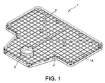
- an exemplary radiolucent dimensioned grid plate 1 is designed to be sufficiently large to ensure that the body part in questions, such as the entire pelvis and proximal femurs (left and right), is captured in a fluoro image.
- the radio-opaque grid (any and all metals, ceramics) has a (1cm) quantifiable pattern (other quantifiable patterns, English) with each individual "block” having a square geometry. These grid lines align parallel to each other in two directions-vertical (cephalad/caudad) 14 and horizontal (medial/lateral) 2 .
- a radiolucent dimensioned grid plate 1 for hip arthroplasty is provided.
- the dimensioned grid plate 1 is "sandwiched" between support plates 4 that have an extended aspect 6 in the caudal direction, to form the grid plate apparatus 19 .
- This caudal aspect has a cutout 5 that matches and mates with an operating table's peg for use in an anterior approach procedure.
- the outer layer of the support plates 4 are joined together at the corners 15 by a solid metal piece that will also serve as the attachment place for the clamps that will attach the a dimensioned grid plate apparatus 19 to the operating table 72 or to the hip positioning apparatus (not shown).
- support rods (not shown) can be added to the caudal aspect.
- two grid lines form a V and are angled at 45 degrees to the vertical and horizontal.
- these two lines represent a guide 3 for quantifying the abduction angle of an acetabular cup used during an arthroplasty procedure.
- the desired angle for the guide 3 relates to the type of implant. Metal on metal implants use a 40 degree angle of abduction, while polyethylene based articular surfaces use a 45 degree angle.
- the left half side of the grid plate apparatus 19 is a mirror image of the right hand side.
- the dimensioned grid plate 1 can have the following radio opaque markings (any and all methods of etching or marking): Two 45 degree angled radio opaque guide lines 3 ; two elliptical etchings which represent the proper version of the acetabular component 8 adjacent and cephalad to the 45 degree lines with a distance of approximately 20 cm from the apex of the two 45 lines (correlates to average standardized measurements of human pelvis between the radiolucent lines representing the quadrilateral surface, the roof of the obturator foramen, and the fossa acetabulae (the "teardrop")); numbers representing the vertical lines with zero being the midline and the numbers counted off in both medial and lateral directions from zero 10 ; letters of the alphabet on both sides of the grid representing the horizontal (x-axis) 9 ; and an image of an anatomical feature, such as a pelvis outline. All these grid lines and markings guide the physician in defining the orientation for insertion of the implants and specifically determining and measuring leg length, offset
- the dimensioned grid plate 1 is enclosed on either side in an epoxy resin that is both transparent and with a plurality of support plates 4 to form the grid plate apparatus 19 .
- the epoxy creates a complete seal for the metal to prevent corrosion and support cleanability of the grid plate apparatus 19 .
- Other manufacturing processes known to those skilled in the art include: laser etched: etched, then filled with radio-opaque marker in etched negative areas, then sandwiched; molded: with metal on support plates 4 ; using tungsten as the radio-opaque material for use in grid lines and numbers; sandwich deposition: printing process (like circuit boards); CNC Machined: back filled and radio-opaque decal: use of radio-opaque ink placed on support plates 4 .
- the plurality of support plates 4 is shown surrounding the dimensioned grid plate 1 .
- This central axis pin 11 is attached to the outer support plates 4 , by conventional means such as a screw threaded through the support plate into the end of the axis pin 11.
- the axis pin 11 will be captured on either end by a screw threaded through the support plates 4 and into the end of the axis pin - on both ends.
- the medial-lateral slot 13 allows +/- 5 cm medial-lateral translation of the dimensioned grid plate 1 relative to the support plates 4 .
- the central axis pin 11 is oriented perpendicularly to the surface of the plurality of support plates 4 and the central axis pin 11 projects upwardly.
- This dimensioned grid plate 1 has a slot 13 .
- the slot 13 allows the dimensioned grid plate 1 to be shifted from side to side or medially-laterally.
- the dimensioned grid plate 1 articulates within the support plates 4 by a central axis pin 11 .
- the medial-lateral slot 13 allows +/- 5 cm medial-lateral translation of the dimensioned grid plate 1 relative to the support plates 4 and the patient 27 .
- the dimensioned grid plate 1 can also be rotated +/- 40 degrees about the central axis pin 11 axis relative to the support plates 4 and the patient 27 .
- the dimensioned grid plate 1 is rotated or translated by using the handle 12 that is attached to the grid plate apparatus 19 .
- the dimensioned grid plate 1 rotates about the central axis pin 11 .
- the slot 13 is configured with scalloped sides or edges that allow the dimensioned grid plate 1 to be indexed at a plurality of positions.
- the central axis pin 11 has a groove 21 about which the dimensioned grid plate 1 will rotate.
- the central axis pin groove 21 will further have a series of countersunk grooves 22 for engagement of spring-loaded ball 23 (for location of rotational position of the dimensioned grid plate 1 relative to the outer support plates.
- the dimensioned grid plate 1 translates in a medial lateral direction along the central axis pin 11 . This translational movement is achieved by utilizing countersunk grooves 26 with a spring-loaded device (SLD) 24 having a uniform groove and countersunk slot configuration.
- SLD spring-loaded device
- the indexing is accomplished by a translation/rotational mechanism 25 .
- the central axis pin 11 has the ability to translate along the medial-lateral slot 13 and engage in any one of a series of positions in the medial lateral direction. This is accomplished by having a plurality of spring-loaded device 25 used in conjunction with a plurality of corresponding countersunk slots 26 . This rotation is accomplished by the configuration of the medial lateral slot 13 .
- the slot 13 is made of a plurality countersunk grooves 26 that are configured to retain the central axis pin 11 . Additionally, the surface opposite 30 one of the plurality of countersunk grooves 26 is configured to retain a spring-loaded device 24 .
- a plurality of spring-loaded devices 24 mediate the movement of the grid 1 .
- the spring-loaded device 25 releasably holds the central axis pin 11 in the selected scalloped or notched position. The engagement/disengagement position and force will be determined based upon spring-loaded device holding capacity.
- the central axis pin 11 can be fluted longitudinally 22 which allows a rotational detent action as the patient (on the grid plate apparatus 20 ) is rotated in the horizontal plane about the central axis pin 1.
- this embodiment allows for use in all surgical approaches to the hip.
- the grid plate apparatus 19 is used as shown in FIG. 6A , the patient is in a supine position with the grid apparatus 19 placed beneath the patient's pelvis.
- the added benefit is having the ability to rotate, translate ML, and ideally position the grid to the anatomy of the patient.
- the dimensioned grid plate 1 has the ability to rotate +/- 40 degrees from the vertical and translate in the medial lateral direction +/- 5cm.
- the dimensioned grid plate 1 can translate cephalad/caudad by adjusting the clamps which fix the dimensioned grid plate apparatus 19 to the bed or the hip positioning device.
- the rotational/translational grid can also be used for an anterior approach procedure.
- the Hilgenreiner's line 31 is a line drawn horizontally through the superior aspect of both triradiate cartilages. It should be horizontal, but is mainly used as a reference for Perkin's line and measurement of the acetabular angle.
- the grid plate apparatus 19 has an extension in the caudad direction that has enough distance to allow the grid to lock onto the operating table 72 and then also ensure that the dimensioned grid plate apparatus 19 is directly behind (posterior) the patients' pelvis.
- the extension piece has a slot 5 cut out that matches the diameter of the peg (not shown) on the surgical table 72 that is being used.
- the peg (not shown) is fixed to the table and so by locking the peg to the plate there will be no motion of the plate 19 relative to the patient 27 during the surgery.
- tables that are conducive to the direct anterior approach were used.
- the present apparatus 1 and method can be used on any radiolucent operating table.
- Fig 6B the patient 27 is placed in the appropriate position for hip replacement surgery.
- the surgeon places the patient 27 in a Lateral Decubitus position; the surgeon positions the dimensioned grid plate 19 directly behind the pelvis of the patient 27 .
- the surgeon will bring in the mobile x-ray machine (C-arm) and align the C-arm beam with the pelvis and grid plate in the anterior posterior plane.
- the image generated by the C-arm will provide a fluoro view of the anterior posterior pelvis and a grid pattern overlay.
- the patient 27 can be placed on his or her side in an appropriate and traditional manner.
- the surgeon will examine the x-ray image to determine subject specific data. Three parameters will be measured and determined at this point: 1) leg length, 2) offset, and 3) cup position.
- the patient's anatomical landmark(s) can be geometrically dimensioned relative to the grid lines. For example, points on the grid line drawn through the bottom of the ischium may be viewed as points on the grid marked along the H grid line. The proximal aspect of the left and right lesser trochanters may be viewed as points on the grid marked as G3 and F3 respectively.
- the distance measured counting or using the grid squares between the ischial axis grid line and the respective two lesser trochanter points is the leg length discrepancy.
- a surgeon's preference may be to use points on the grid marking the greater trochanter in conjunction with the grid lines through the obturator foramina.
- Offset The offset of the femoral component is the distance from the center of rotation of the femoral head to a line bisecting the long axis of the stem.): In a similar technique to leg length, offset can be quantified. Corresponding radiographic points identified on the patient's left and right pelvis and proximal femur can be measured with the grid lines and blocks. The difference between the left and right measurements will quantify the offset mismatch and provide the surgeon with a numerical number to allow restoration of proper offset.
- the optimal position of the acetabular component can be determined using the dimensioned grid plate apparatus 19 as an alignment and measurement device.
- the dimensioned grid plate apparatus 19 has a 45 degree angled metal line 3 .
- the radiographic image will display the trial or final implanted acetabular cup positioned in the acetabulum relative to the 45 degree guide line 3 that will be superimposed on the image.
- the cup position can then be adjusted based upon image feedback until correct positioning of the final implant is determined.
- a dimensioned grid plate 20 can be adapted for a variety of end-uses such as to facilitate the placement of an implant in arthroplasty or trauma procedure; for fracture reduction/correction during a trauma procedure or for deformity correction planning.
- the proximal femoral angle at 40 is determined.
- the distal femoral angle is determined at 42 .
- the proximal tibial angle 42 is determined.
- the distal tibial angle 43 is determined to form the "X" axis relative to the "Y" axis 35 of the dimensional grid plate apparatus 20 .
- the Y axis 35 is the center line that creates a mirror image of grid and reference lines on either side of it, thus allowing use for either a left or a right leg application.
- 49 marks the center of the femoral head location.
- the proximal pelvic section of the device also has two 45 degree lines 45 that intersect at the center of the femoral head point 49 . These same lines can also be used to quantify femoral neck angle 51 .
- the knee section 48 is comprised of a grid pattern matching that of grid plate 20 .
- the ankle section is comprised of a grid pattern matching that of grid plate 20 .
- the knee section has a central x-axis 42 .
- the ankle section has central x-axis 43 .
- the knee grid section has two 3 degree lines 46 for use in quantifying alignment as needed.
- a dimensioned grid plate apparatus 20 for use with a trauma procedure on a lower extremity is disclosed.
- the trauma implications go beyond the pelvis and acetabulum.
- a larger grid plate 20 that runs from the patient's pelvis to beyond the ankle allows a surgeon to confirm length using the contralateral side. Additionally, the grid plate 20 allows the surgeon to confirm alignment prior to and after placement of an implant.
- the y-axis 35 correlates with the mechanical axis that runs from the head of the femur through bony landmarks in the tibial plateau through to the distal tibia. Angles that may create the x-axis 40 (depending upon fracture location) could be: proximal femoral angle; lateral distal femoral angle; medial proximal tibial angle; distal tibial angle.
- the patient's anatomical landmark(s) can be geometrically dimensioned relative to the grid lines.
- points on the grid line drawn through the bottom of the ischium may be viewed as points on the grid marked along the H grid line 91 .
- the proximal aspect of the left lesser trochanters of the affected hip may be viewed as A point on the grid marked as G6.5 93 on the unaffected hip it can be determined that this same point is G5.5.
- the distance measured counting or using the grid squares between the ischial axis grid line H 91 and the respective two lesser trochanter points is the leg length discrepancy, relating to the inserted cup 90 .
- deformity correction works much the same as the trauma description above.
- An existing deformity is evaluated against the patient's contralateral side.
- the grid plate apparatus 19 or 20 is used to ensure that the bone length and alignment correlate to the contralateral side.
- the grid plate apparatus 19 or 20 allows the surgeon to evaluate whether the osteotomy is sufficient to correct alignment and/or length intraoperatively, as well as making it visually easier to plan a correction procedure by using the grid to obtain pre-operative radiographs (i.e. , surgeon does not have to draw his own lines and angles on plain radiographs to try to determine the appropriate amount of bone to remove and/or cut and re-angle).
- CLINICAL STUDY Example This retrospective cohort study reviews postoperative radiographic findings of 160 consecutive primary total hip athroplasties performed through an anterior supine approach with the aid of intraoperative fluoroscopy.
- the control group was 100 total hip athroplasties performed without the grid plate apparatus 19 or 20 .
- the study group was 54 total hip athroplasties performed with the use of the grid plate apparatus 19 or 20 to aid in assessing acetabular component inclination, femoral offset, and leg length.
- Femoral offset, component abduction and leg length differences were measured by two readers blinded to the group status. Surgeon aims included an inclination angle of 40-45 degrees and a leg length and offset equal to the contralateral side. Additionally, the two groups were assessed for differences in demographics and clinical outcomes including complications such as dislocation and symptomatic leg length discrepancy.
- Inclination angle averaged 42 degrees (SD 1.5 degrees) for the grid group compared to 45 degrees (SD 4 degrees).
Description
- The present invention relates to a fluoroscopic alignment plate apparatus for use in various orthopedic applications, such as, an anterior total hip arthroplasty.
- Many of the radiographic parameters essential to total hip arthroplasty (THA) component performance, such as wear, and stability, can be assessed intraoperatively with fluoroscopy. However even with intraoperative fluoroscopic guidance, the placement of an implant may still not be as close as desired by the surgeon. For example, malpositioning of the acetabular component during hip arthroplasty can lead to problems. For the acetabular implant to be inserted in the proper position relative to the pelvis during hip arthroplasty requires that the surgeon know the position of the patient's pelvis during surgery. Unfortunately, the position of the patient's pelvis varies widely during surgery and from patient to patient.
- Various devices have been suggested to reduce malpositioning of these surgical components. For example, a transverse acetabular ligament has been suggested as a qualitative marker of the orientation of the acetabulum. (Archbold HA, et al. The Transverse Acetabular Ligament; an Aid to Orientation of the Acetabular Component During Primary Total Hip Replacement: a Preliminary Study of 1000 Cases Investigating Postoperative Stability, J Bone Joint Surg BR. 2006 Jul; 88(7):883-7. However, it has been suggested that the acetabulum may be deteriorated due to arthritis. Others have proposed using a tripod device that uses the anatomy of the ipsilateral hemi pelvis as the guide to position the prosthetic acetabular component.
US Patent Publication Number 20090306679 . This instrument has three points. The first leg is positioned in the area of the posterior inferior acetabulum, a second leg is positioned in the area of the anterior superior iliac spine and a third leg is positioned on the ileum of the subject. Another prior art alignment fixture is described inWO201105 3491 . However, a need exists in the industry for a device that is not implantable or invasive and is adaptable to a variety of applications. - The invention is disclosed in
claim 1 with preferred embodiments in the dependent claims. The present invention, provides an apparatus for determining and measuring leg length, offset, and cup position during arthroplasty surgery by using a dimensioned grid plate positioned under the patient in conjunction with x-ray to measure variables, such as, hip implant position to determine the relative leg length and offset measurements for the implant. Arthroplasty surgery includes, for example: hip (anterior approach), hip (posterior approach), knee, ankle, elbow, and shoulder. - The apparatus of this invention includes a dimensioned radiolucent grid plate having a known quantifiable grid pattern which has geometry with known dimensioned symbols or numbers representing each or multiple grid lines. The dimensioned grid plate has a known angled grid line which may be any angle between about 30 and 60 degrees, preferably 45 degrees +/- 15 degrees which are used for determination and alignment of the prosthetic acetabular cup position (version, abduction) in any and all x-ray views and a medial-lateral slot in the grid plate. At least one of a plurality of support plates are configured to retain the dimensioned grid plate and a central axis pin connected to at least one of the plurality of support plates. A medial lateral slot is configured to retain a pin and to allow medial-lateral translation of the grid plate relative to the support members and to rotate around the axis of the pin. This rotation is accomplished by the configuration of the medial lateral slot. The slot is made of a plurality countersunk grooves that are configured to retain the central axis pin. Additionally, the surface opposite one of the plurality of countersunk grooves is configured to retain a spring-loaded device. A plurality of spring-loaded devices mediate the movement of the grid.
- An exemplary method employs x-rays to obtain an image that shows the position of the pelvis and both proximal femurs relative to the dimensioned grid plate. Subject specific data from an image of a patient consists of: data on a leg length, an off set and a cup position.
- In another example a method to facilitate fracture reduction during a trauma procedure or to correct a deformity in a subject involves placing the dimensioned radiolucent grid plate apparatus adjacent to a patient during a procedure; and obtaining subject specific data from an image of the patient, wherein the data consists of a "Y" axis corresponding to an anatomical axis of the patient and an "X" axis corresponding to an angle related to an abnormality.
- The drawing shows schematically a fluoroscopic alignment plate apparatus and an exemplary method of use according to an example form of the present invention. The invention description refers to the accompanying drawings:
-
FIG. 1 is a perspective view of an exemplary grid plate; -
FIG. 2 is a front view of an embodiment of the dimensioned grid plate apparatus of the present invention; -
FIG. 3 is a side view of an embodiment of the dimensioned grid plate apparatus of the present invention; -
FIG. 4A is a side view of the apparatus of the apparatus of the present invention; -
FIG. 4B is a top view of the translational/rotational mechanism of the present invention; -
FIG. 5 is a rear view of an embodiment of the dimensioned grid plate apparatus of the present invention; -
FIG. 6A is an illustrative sketch showing the relationship of the patient to the apparatus in an anterior approach. -
FIG. 6B is an illustrative sketch showing the relationship of the patient to the apparatus in an posterior approach; -
FIG. 7 is a front view of another embodiment of the dimensioned grid plate apparatus of the present invention; -
FIG. 8 is a sketch of x-ray view showing hip anatomy with implant and the grid overlay. -
FIG. 9 is a schematic of an x-ray view of the hip anatomy with implant grid overview. - The present invention may be understood more readily by reference to the following detailed description of the invention. It is to be understood that this invention is not limited to the specific devices, methods, conditions or parameters described herein, and that the terminology used herein is for the purpose of describing particular embodiments by way of example only and is not intended to be limiting of the claimed invention. Also, as used in the specification including the appended claims, the singular forms "a," "an," and "the" include the plural, and reference to a particular numerical value includes at least that particular value, unless the context clearly dictates otherwise. Ranges may be expressed herein as from "about" or "approximately" one particular value and/or to "about" or "approximately" another particular value. When such a range is expressed, another embodiment includes from the one particular value and/or to the other particular value. Similarly, when values are expressed as approximations, by use of the antecedent "about," it will be understood that the particular value forms another embodiment.
- These and other aspects, features and advantages of the invention will be understood with reference to the detailed description herein, and will be realized by means of the various elements and combinations particularly pointed out in the appended claims. It is to be understood that both the foregoing general description and the following detailed description of the invention are exemplary and explanatory of preferred embodiments of the inventions, and are not restrictive of the invention as claimed. Unless defined otherwise, all technical and scientific terms used herein have the same meaning as commonly understood by one of ordinary skill in the art to which this invention belongs.
- Now referring to
FIG. 1 an exemplary radiolucent dimensionedgrid plate 1 is designed to be sufficiently large to ensure that the body part in questions, such as the entire pelvis and proximal femurs (left and right), is captured in a fluoro image. The radio-opaque grid (any and all metals, ceramics) has a (1cm) quantifiable pattern (other quantifiable patterns, English) with each individual "block" having a square geometry. These grid lines align parallel to each other in two directions-vertical (cephalad/caudad) 14 and horizontal (medial/lateral) 2. - Now referring to
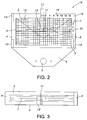
FIG. 2 , a radiolucent dimensionedgrid plate 1 for hip arthroplasty is provided. The dimensionedgrid plate 1 is "sandwiched" betweensupport plates 4 that have anextended aspect 6 in the caudal direction, to form thegrid plate apparatus 19.. This caudal aspect has acutout 5 that matches and mates with an operating table's peg for use in an anterior approach procedure. The outer layer of thesupport plates 4 are joined together at thecorners 15 by a solid metal piece that will also serve as the attachment place for the clamps that will attach the a dimensionedgrid plate apparatus 19 to the operating table 72 or to the hip positioning apparatus (not shown). For strength, support rods (not shown) can be added to the caudal aspect. - In this dimensioned
grid plate 1, two grid lines form a V and are angled at 45 degrees to the vertical and horizontal. In this dimensionedgrid plate 1, these two lines represent aguide 3 for quantifying the abduction angle of an acetabular cup used during an arthroplasty procedure. However, the desired angle for theguide 3 relates to the type of implant. Metal on metal implants use a 40 degree angle of abduction, while polyethylene based articular surfaces use a 45 degree angle. The left half side of thegrid plate apparatus 19 is a mirror image of the right hand side. The dimensionedgrid plate 1 can have the following radio opaque markings (any and all methods of etching or marking): Two 45 degree angled radioopaque guide lines 3; two elliptical etchings which represent the proper version of theacetabular component 8 adjacent and cephalad to the 45 degree lines with a distance of approximately 20 cm from the apex of the two 45 lines (correlates to average standardized measurements of human pelvis between the radiolucent lines representing the quadrilateral surface, the roof of the obturator foramen, and the fossa acetabulae (the "teardrop")); numbers representing the vertical lines with zero being the midline and the numbers counted off in both medial and lateral directions from zero 10; letters of the alphabet on both sides of the grid representing the horizontal (x-axis) 9; and an image of an anatomical feature, such as a pelvis outline. All these grid lines and markings guide the physician in defining the orientation for insertion of the implants and specifically determining and measuring leg length, offset, cup placement, and femoral head center of rotation and mechanical axis of lower limb. - The dimensioned
grid plate 1 is enclosed on either side in an epoxy resin that is both transparent and with a plurality ofsupport plates 4 to form thegrid plate apparatus 19. The epoxy creates a complete seal for the metal to prevent corrosion and support cleanability of thegrid plate apparatus 19. Other manufacturing processes known to those skilled in the art include: laser etched: etched, then filled with radio-opaque marker in etched negative areas, then sandwiched; molded: with metal onsupport plates 4; using tungsten as the radio-opaque material for use in grid lines and numbers; sandwich deposition: printing process (like circuit boards); CNC Machined: back filled and radio-opaque decal: use of radio-opaque ink placed onsupport plates 4. - Now referring to
FIG. 3 , the plurality ofsupport plates 4 is shown surrounding the dimensionedgrid plate 1. Thiscentral axis pin 11 is attached to theouter support plates 4, by conventional means such as a screw threaded through the support plate into the end of theaxis pin 11. Theaxis pin 11 will be captured on either end by a screw threaded through thesupport plates 4 and into the end of the axis pin - on both ends. The medial-lateral slot 13 allows +/- 5 cm medial-lateral translation of the dimensionedgrid plate 1 relative to thesupport plates 4. Thecentral axis pin 11 is oriented perpendicularly to the surface of the plurality ofsupport plates 4 and thecentral axis pin 11 projects upwardly. This dimensionedgrid plate 1 has aslot 13. Theslot 13 allows the dimensionedgrid plate 1 to be shifted from side to side or medially-laterally. - Now referring to
FIG. 4A and 4B , the dimensionedgrid plate 1 articulates within thesupport plates 4 by acentral axis pin 11. The medial-lateral slot 13 allows +/- 5 cm medial-lateral translation of the dimensionedgrid plate 1 relative to thesupport plates 4 and thepatient 27. The dimensionedgrid plate 1 can also be rotated +/- 40 degrees about thecentral axis pin 11 axis relative to thesupport plates 4 and thepatient 27. The dimensionedgrid plate 1 is rotated or translated by using thehandle 12 that is attached to thegrid plate apparatus 19. The dimensionedgrid plate 1 rotates about thecentral axis pin 11. - The
slot 13 is configured with scalloped sides or edges that allow the dimensionedgrid plate 1 to be indexed at a plurality of positions. Thecentral axis pin 11 has agroove 21 about which the dimensionedgrid plate 1 will rotate. The centralaxis pin groove 21 will further have a series of countersunkgrooves 22 for engagement of spring-loaded ball 23 (for location of rotational position of the dimensionedgrid plate 1 relative to the outer support plates. Furthermore, the dimensionedgrid plate 1 translates in a medial lateral direction along thecentral axis pin 11. This translational movement is achieved by utilizing countersunkgrooves 26 with a spring-loaded device (SLD) 24 having a uniform groove and countersunk slot configuration. The indexing is accomplished by a translation/rotational mechanism 25. Thecentral axis pin 11 has the ability to translate along the medial-lateral slot 13 and engage in any one of a series of positions in the medial lateral direction. This is accomplished by having a plurality of spring-loadeddevice 25 used in conjunction with a plurality of corresponding countersunkslots 26. This rotation is accomplished by the configuration of the mediallateral slot 13. - The
slot 13 is made of a plurality countersunkgrooves 26 that are configured to retain thecentral axis pin 11. Additionally, the surface opposite 30 one of the plurality of countersunkgrooves 26 is configured to retain a spring-loadeddevice 24. A plurality of spring-loadeddevices 24 mediate the movement of thegrid 1. The spring-loadeddevice 25 releasably holds thecentral axis pin 11 in the selected scalloped or notched position. The engagement/disengagement position and force will be determined based upon spring-loaded device holding capacity. Thecentral axis pin 11 can be fluted longitudinally 22 which allows a rotational detent action as the patient (on the grid plate apparatus 20) is rotated in the horizontal plane about thecentral axis pin 1. - Now referring to
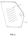
FIG. 5 , on the underside of thegrid plate apparatus 19 there are strips of an adhesive material such asVELCRO 17 to further secure the plate to the table. This prevents thegrid plate apparatus 19 from moving relative to the surgical table or patient during the surgical procedure. - Now referring to
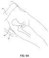
FIG. 6A , this embodiment allows for use in all surgical approaches to the hip. For the anterior approach, thegrid plate apparatus 19 is used as shown inFIG. 6A , the patient is in a supine position with thegrid apparatus 19 placed beneath the patient's pelvis. For the posterior approach as shown inFIG 6B . the added benefit is having the ability to rotate, translate ML, and ideally position the grid to the anatomy of the patient. The dimensionedgrid plate 1 has the ability to rotate +/- 40 degrees from the vertical and translate in the medial lateral direction +/- 5cm. The dimensionedgrid plate 1 can translate cephalad/caudad by adjusting the clamps which fix the dimensionedgrid plate apparatus 19 to the bed or the hip positioning device. The rotational/translational grid can also be used for an anterior approach procedure. The Hilgenreiner'sline 31 is a line drawn horizontally through the superior aspect of both triradiate cartilages. It should be horizontal, but is mainly used as a reference for Perkin's line and measurement of the acetabular angle. - The
grid plate apparatus 19 has an extension in the caudad direction that has enough distance to allow the grid to lock onto the operating table 72 and then also ensure that the dimensionedgrid plate apparatus 19 is directly behind (posterior) the patients' pelvis. The extension piece has aslot 5 cut out that matches the diameter of the peg (not shown) on the surgical table 72 that is being used. The peg (not shown) is fixed to the table and so by locking the peg to the plate there will be no motion of theplate 19 relative to the patient 27 during the surgery. In testing that was performed, tables that are conducive to the direct anterior approach were used. Thepresent apparatus 1 and method can be used on any radiolucent operating table. - For a posterior surgical approach,
Fig 6B , thepatient 27 is placed in the appropriate position for hip replacement surgery. The surgeon places the patient 27 in a Lateral Decubitus position; the surgeon positions the dimensionedgrid plate 19 directly behind the pelvis of thepatient 27. Once the surgeon has the trial implants or final implants inserted in the correct position inside the body, he or she will bring in the mobile x-ray machine (C-arm) and align the C-arm beam with the pelvis and grid plate in the anterior posterior plane. The image generated by the C-arm will provide a fluoro view of the anterior posterior pelvis and a grid pattern overlay. For the use in a posterior surgical approach, the patient 27 can be placed on his or her side in an appropriate and traditional manner. The surgeon will examine the x-ray image to determine subject specific data. Three parameters will be measured and determined at this point: 1) leg length, 2) offset, and 3) cup position. - Leg length: In quantifying leg length discrepancy, the patient's anatomical landmark(s) can be geometrically dimensioned relative to the grid lines. For example, points on the grid line drawn through the bottom of the ischium may be viewed as points on the grid marked along the H grid line. The proximal aspect of the left and right lesser trochanters may be viewed as points on the grid marked as G3 and F3 respectively.
- The distance measured counting or using the grid squares between the ischial axis grid line and the respective two lesser trochanter points (G3 and F3 for example) is the leg length discrepancy.) Alternatively, a surgeon's preference may be to use points on the grid marking the greater trochanter in conjunction with the grid lines through the obturator foramina.
- Offset. The offset of the femoral component is the distance from the center of rotation of the femoral head to a line bisecting the long axis of the stem.): In a similar technique to leg length, offset can be quantified. Corresponding radiographic points identified on the patient's left and right pelvis and proximal femur can be measured with the grid lines and blocks. The difference between the left and right measurements will quantify the offset mismatch and provide the surgeon with a numerical number to allow restoration of proper offset.
- Pelvic Acetabular Implant commonly referred to as the "cup": The optimal position of the acetabular component can be determined using the dimensioned
grid plate apparatus 19 as an alignment and measurement device. The dimensionedgrid plate apparatus 19 has a 45 degree angledmetal line 3. The radiographic image will display the trial or final implanted acetabular cup positioned in the acetabulum relative to the 45degree guide line 3 that will be superimposed on the image. The cup position can then be adjusted based upon image feedback until correct positioning of the final implant is determined. - Now referring to
FIGS. 7-8 a dimensionedgrid plate 20 can be adapted for a variety of end-uses such as to facilitate the placement of an implant in arthroplasty or trauma procedure; for fracture reduction/correction during a trauma procedure or for deformity correction planning. In operation, the proximal femoral angle at 40 is determined. Next the distal femoral angle is determined at 42. Next theproximal tibial angle 42 is determined. Next thedistal tibial angle 43 is determined to form the "X" axis relative to the "Y"axis 35 of the dimensionalgrid plate apparatus 20. - The
Y axis 35 is the center line that creates a mirror image of grid and reference lines on either side of it, thus allowing use for either a left or a right leg application. 49 marks the center of the femoral head location. The proximal pelvic section of the device also has two 45degree lines 45 that intersect at the center of thefemoral head point 49. These same lines can also be used to quantifyfemoral neck angle 51. Theknee section 48 is comprised of a grid pattern matching that ofgrid plate 20. Similarly, the ankle section is comprised of a grid pattern matching that ofgrid plate 20. The knee section has acentral x-axis 42. Similarly, the ankle section hascentral x-axis 43. The knee grid section has two 3degree lines 46 for use in quantifying alignment as needed. - In another embodiment, and now referring to
FIG. 8 , a dimensionedgrid plate apparatus 20 for use with a trauma procedure on a lower extremity is disclosed. The trauma implications go beyond the pelvis and acetabulum. Alarger grid plate 20 that runs from the patient's pelvis to beyond the ankle allows a surgeon to confirm length using the contralateral side. Additionally, thegrid plate 20 allows the surgeon to confirm alignment prior to and after placement of an implant. The y-axis 35 correlates with the mechanical axis that runs from the head of the femur through bony landmarks in the tibial plateau through to the distal tibia. Angles that may create the x-axis 40 (depending upon fracture location) could be: proximal femoral angle; lateral distal femoral angle; medial proximal tibial angle; distal tibial angle. - Now referring to
FIG. 9 , an x-ray view of hip anatomy within implant and grid overview is shown. In quantifying leg length discrepancy, the patient's anatomical landmark(s) can be geometrically dimensioned relative to the grid lines. For example, points on the grid line drawn through the bottom of the ischium may be viewed as points on the grid marked along theH grid line 91. For example the proximal aspect of the left lesser trochanters of the affected hip may be viewed as A point on the grid marked as G6.5 93 on the unaffected hip it can be determined that this same point is G5.5. For example, the distance measured counting or using the grid squares between the ischial axisgrid line H 91 and the respective two lesser trochanter points (G6.5 and G5.5 for example) is the leg length discrepancy, relating to the insertedcup 90. - In another embodiment, deformity correction works much the same as the trauma description above. An existing deformity is evaluated against the patient's contralateral side. The
grid plate apparatus grid plate apparatus - CLINICAL STUDY Example: This retrospective cohort study reviews postoperative radiographic findings of 160 consecutive primary total hip athroplasties performed through an anterior supine approach with the aid of intraoperative fluoroscopy. The control group was 100 total hip athroplasties performed without the
grid plate apparatus grid plate apparatus - Inclination angle averaged 42 degrees (SD 1.5 degrees) for the grid group compared to 45 degrees (
SD 4 degrees). - Femoral offset averaged + 1.5 mm (
SD 1 mm) compared to the contralateral side for the grid group compared to - 1 mm (SD 3 mm) for the control group. - Leg length differences averaged + 1.5 mm (
SD 1 mm) compared to the contralateral side for the grid group compared to - 1 mm (SD 3 mm) for the control group. - There were no statistically significant differences in age, gender, BMI or dislocation rate between groups. However, the group using the
grid plate apparatus 20 had a lower rate of symptomatic leg length discrepancy than the control group. - While intraoperative use of fluoroscopy to guide femoral offset, leg length and acetabular inclination is helpful, a radiopaque guide with abduction angle references can be helpful to improve precision and accuracy in accomplishing the orthopedic surgeon's goals.
- While the invention has been described with reference to preferred and example embodiments, it will be understood by those skilled in the art that a variety of modifications, additions and deletions are within the scope of the invention, as defined by the following claims.
Claims (6)
- An apparatus (19) comprising:a radiolucent dimensioned grid plate (1) having a top surface and a bottom surface, at least one of the top and bottom surfaces having a plurality of dimensioned radio-opaque horizontal lines (14) and vertical lines (2) formed thereon, the horizontal lines (14) and vertical lines (2) being spaced apart as in a grid pattern with identical distance between each subsequent vertical line (2) in a horizontal direction and each subsequent horizontal line (14) in a vertical direction, and an oblique grid line at an angle of between about 30 to 50 degrees relative to the horizontal lines (14) , and a medial-lateral slot (13) formed in one of the top and bottom surfaces of said grid plate (1), a longer side of a shape of the medial-lateral slot being parallel to the horizontal lines;at least one of a plurality of support plates (4) configured to retain said dimensioned grid plate (1) by receiving one of the top and bottom surface on a front or back surface of at least one of the plurality of support plates (4); anda central axis pin (11) connected to at least one of said plurality of support plates (4) perpendicularly relative to a plane of the at least one support plates (4),wherein said medial-lateral slot (13) is configured to retain the central axis pin (11) therethrough,wherein the medial-lateral slot (13) is configured to allow medial-lateral translation of the grid plate (1) relative to a horizontal line of said support plates (4), the horizontal line of the support plates being generally aligned with the longer side of the shape of the medial-lateral slot,wherein the medial-lateral slot (13) is configured to allow the grid plate (1) to rotate around the axis of said central axis pin (11) relative to the support plates (4), andwherein the medial-lateral slot (13) is comprised of a plurality countersunk grooves (26) that are configured to retain said central axis pin (11) to the grid plate (1).
- The apparatus of claim 1 wherein the surface opposite the one of the plurality of countersunk grooves (26) in the top surface or bottom surface of the grid plate (1) is configured to retain a spring-loaded device (25).
- The apparatus of claim 1 wherein said plurality of support plates (4) have an extended portion including a hole (5) extending through the plurality of support plates (4) coaxially, the hole (5) being sized to accommodate an operating table peg for attaching the support plates (4) to an operating table (72).
- The apparatus of claim 1 further comprising said grid plate (1) having a plurality of radio-opaque elliptical figures representing an acetabular component.
- The apparatus of claim 1 further comprising a radio-opaque image of an anatomical feature on said grid, the anatomical feature being a pelvis outline.
- The apparatus of claim 1 further comprising an adhesive material (17) applied to the bottom surface of at least one of the plurality of support plates (4) to secure said apparatus to an operating table (72).
Applications Claiming Priority (2)
| Application Number | Priority Date | Filing Date | Title |
|---|---|---|---|
| US201161525259P | 2011-08-19 | 2011-08-19 | |
| PCT/US2012/051512 WO2013028582A1 (en) | 2011-08-19 | 2012-08-18 | Alignment plate apparatus and method of use |
Publications (3)
| Publication Number | Publication Date |
|---|---|
| EP2744431A1 EP2744431A1 (en) | 2014-06-25 |
| EP2744431A4 EP2744431A4 (en) | 2015-03-04 |
| EP2744431B1 true EP2744431B1 (en) | 2016-04-20 |
Family
ID=47746795
Family Applications (1)
| Application Number | Title | Priority Date | Filing Date |
|---|---|---|---|
| EP12825370.5A Active EP2744431B1 (en) | 2011-08-19 | 2012-08-18 | Alignment plate apparatus |
Country Status (9)
| Country | Link |
|---|---|
| US (2) | US8611504B2 (en) |
| EP (1) | EP2744431B1 (en) |
| JP (1) | JP3192485U (en) |
| CN (1) | CN204092141U (en) |
| AU (1) | AU2012299072B2 (en) |
| BR (1) | BR212014003881U2 (en) |
| CA (1) | CA2845839C (en) |
| WO (1) | WO2013028582A1 (en) |
| ZA (1) | ZA201401222B (en) |
Families Citing this family (28)
| Publication number | Priority date | Publication date | Assignee | Title |
|---|---|---|---|---|
| JP6172534B2 (en) | 2011-09-29 | 2017-08-02 | アースロメダ、 インコーポレイテッド | System used for precise prosthesis positioning in hip arthroplasty |
| US10441236B2 (en) | 2012-10-19 | 2019-10-15 | Biosense Webster (Israel) Ltd. | Integration between 3D maps and fluoroscopic images |
| US9750459B2 (en) | 2012-11-05 | 2017-09-05 | Andrew B. Lytle | Imaging alignment apparatus and method of use therefor |
| AU2014217929B2 (en) | 2013-02-18 | 2018-04-19 | Orthogrid Systems Holdings, Llc | Alignment plate apparatus and system and method of use |
| US9597096B2 (en) | 2013-03-15 | 2017-03-21 | Arthromeda, Inc. | Systems and methods for providing alignment in total knee arthroplasty |
| EP3565474A1 (en) * | 2013-04-26 | 2019-11-13 | Arealis, Georgios | Pathology localizer and therapeutical procedure guide system |
| US10052060B2 (en) * | 2013-10-31 | 2018-08-21 | Andrew B. Lytle | System and method for adjusting alignment of a body part with an imaging apparatus |
| USD750776S1 (en) | 2014-02-27 | 2016-03-01 | Andrew B. Lytle | Surgical alignment device |
| US20170296273A9 (en) * | 2014-03-17 | 2017-10-19 | Roy Anthony Brown | Surgical Targeting Systems and Methods |
| US10390843B1 (en) * | 2015-02-03 | 2019-08-27 | Dartmouth-Hitchcock Clinic | Trajectory and aiming guide for use with fluoroscopy |
| USD775344S1 (en) * | 2015-04-07 | 2016-12-27 | Tecmen Electronics Co., Ltd. | Filter cartridge for welding respirator |
| US10123883B2 (en) | 2015-07-22 | 2018-11-13 | Karl Baird | Length/offset reproducing device for total hip arthroplasty |
| US10098707B2 (en) | 2015-08-17 | 2018-10-16 | Orthogrid Systems Inc. | Surgical positioning system, apparatus and method of use |
| USD788300S1 (en) | 2015-10-27 | 2017-05-30 | Orthogrid Systems, Inc. | Grid positioning device |
| JP2019517323A (en) * | 2016-06-03 | 2019-06-24 | デピュイ・シンセス・プロダクツ・インコーポレイテッド | Surgical template with radiopaque marking |
| CN106091865A (en) * | 2016-06-16 | 2016-11-09 | 国家电网公司 | Eight foundation bolts are with the measuring method of packet size error and instrument |
| JP6436586B2 (en) * | 2016-09-02 | 2018-12-12 | 学校法人北里研究所 | Leg position holder |
| TWI649067B (en) * | 2017-03-01 | 2019-02-01 | 醫百科技股份有限公司 | Positioning corrector |
| US10905477B2 (en) * | 2017-03-13 | 2021-02-02 | Globus Medical, Inc. | Bone stabilization systems |
| JP6876524B2 (en) * | 2017-05-26 | 2021-05-26 | 温雄 名倉 | Bone alignment check sheet |
| US10716682B2 (en) * | 2017-07-19 | 2020-07-21 | Acumed Llc | Orthopedic alignment guide |
| US10451411B1 (en) * | 2017-08-30 | 2019-10-22 | Katherine Joan Bradley | Multifunctional centering tool |
| USD870893S1 (en) * | 2017-11-22 | 2019-12-24 | Guoxiang He | Lumbar vertebra correcting instrument |
| US10813637B2 (en) | 2018-02-21 | 2020-10-27 | Ethicon Llc | Three dimensional adjuncts |
| USD882782S1 (en) | 2018-02-21 | 2020-04-28 | Ethicon Llc | Three dimensional adjunct |
| US10959721B2 (en) | 2018-02-21 | 2021-03-30 | Ethicon Llc | Three dimensional adjuncts |
| US11490890B2 (en) | 2019-09-16 | 2022-11-08 | Cilag Gmbh International | Compressible non-fibrous adjuncts |
| US11672537B2 (en) | 2019-09-16 | 2023-06-13 | Cilag Gmbh International | Compressible non-fibrous adjuncts |
Family Cites Families (74)
| Publication number | Priority date | Publication date | Assignee | Title |
|---|---|---|---|---|
| US2344824A (en) * | 1944-03-21 | Method and means of making x-ray | ||
| US2523050A (en) * | 1950-09-19 | Method and apparatus used in | ||
| US865418A (en) * | 1905-04-10 | 1907-09-10 | Gerhard Moe | Background for photographic measurements. |
| US2245350A (en) * | 1939-05-23 | 1941-06-10 | George R Marshall | Sacral foramina finder |
| US3542022A (en) * | 1968-02-28 | 1970-11-24 | Richard W Bartnik | Template guide for medication injection into gluteus medius muscle area |
| US3547121A (en) * | 1968-03-04 | 1970-12-15 | Mount Sinai Hospital Research | Abdominal grid for intrauterine fetal transfusion |
| US3639764A (en) * | 1969-04-02 | 1972-02-01 | Packard Instrument Co Inc | Bone-density measuring instrument |
| BE789486A (en) * | 1971-12-30 | 1973-01-15 | Buckbee Mears Co | RONTGEN SPOKES BLOCKING GRID |
| US3999504A (en) * | 1975-09-22 | 1976-12-28 | Kearse George P | Insulin injection reminder |
| US4228796A (en) * | 1979-03-19 | 1980-10-21 | Gardiner Marie A | Insulin injection guide |
| US4583538A (en) * | 1984-05-04 | 1986-04-22 | Onik Gary M | Method and apparatus for stereotaxic placement of probes in the body utilizing CT scanner localization |
| DE3417609A1 (en) * | 1984-05-11 | 1985-11-14 | Waldemar Link (Gmbh & Co), 2000 Hamburg | ARRANGEMENT FOR PRODUCING ANATOMICALLY APPROPRIATE ENDOPROTHESIS |
| US4630375A (en) * | 1985-05-02 | 1986-12-23 | Spolyar John L | Apparatus for gauging and determining spatial coordinates for a source of radiation to be employed in obtaining a radiograph of a patient |
| US4838265A (en) * | 1985-05-24 | 1989-06-13 | Cosman Eric R | Localization device for probe placement under CT scanner imaging |
| US4823476A (en) * | 1986-08-12 | 1989-04-25 | Curtin Marilyn A | Method and apparatus for measuring physical attributes of a human body |
| US4883053A (en) * | 1987-09-18 | 1989-11-28 | Beth Israel Hospital | Self-supporting angulator device for precise percutaneous insertion of a needle or other object |
| US4985019A (en) * | 1988-03-11 | 1991-01-15 | Michelson Gary K | X-ray marker |
| US5020088A (en) * | 1988-03-25 | 1991-05-28 | Tobin John A | Tissue sample localizer device and method |
| US5002735A (en) * | 1988-07-12 | 1991-03-26 | Mark T. Alberhasky | Tissue analysis device |
| US4953193A (en) * | 1988-08-25 | 1990-08-28 | Robinson Norman L | Fastening combination having special utility in affixing an X-ray marking device to a cassette adapted to hold X-ray film |
| US5178146A (en) * | 1988-11-03 | 1993-01-12 | Giese William L | Grid and patient alignment system for use with MRI and other imaging modalities |
| US4918715A (en) * | 1989-05-01 | 1990-04-17 | Webb Research Ii Corporation | Image location marking devices for radiographs, method of making and methods of use |
| US5030223A (en) | 1989-06-30 | 1991-07-09 | Iowa State University Research Foundation, Inc. | Head mounted stereotaxic apparatus |
| US5052035A (en) * | 1989-11-02 | 1991-09-24 | Webb Research Ii Corporation | Image location marking devices for radiographs, method of making and methods of use |
| US5105457A (en) * | 1990-04-19 | 1992-04-14 | Glassman Stuart L | Mammograph x-ray grid |
| US5285785A (en) * | 1991-10-30 | 1994-02-15 | Meyer Seymour W | Apparatus and method for locating foreign bodies in humans and animals |
| US5232452A (en) * | 1991-12-13 | 1993-08-03 | Beekley Corporation | Radiology marker system and dispenser |
| US5342366A (en) * | 1992-02-19 | 1994-08-30 | Biomet, Inc. | Surgical instruments for hip revision |
| US5260985A (en) * | 1992-08-14 | 1993-11-09 | Mosby Richard A | Conforming localization/biopsy grid and control apparatus |
| US5634904A (en) * | 1993-10-26 | 1997-06-03 | Battenfield; Harold L. | Universal template for knee injections |
| US20040015176A1 (en) | 1994-06-20 | 2004-01-22 | Cosman Eric R. | Stereotactic localizer system with dental impression |
| EP0714636B1 (en) * | 1994-11-28 | 2003-04-16 | The Ohio State University | Interventional medicine apparatus |
| US5950320A (en) * | 1997-08-29 | 1999-09-14 | Dorsey; Thomas R. | Medico-scientific measuring device |
| US6366643B1 (en) * | 1998-10-29 | 2002-04-02 | Direct Radiography Corp. | Anti scatter radiation grid for a detector having discreet sensing elements |
| US6690767B2 (en) * | 1998-10-29 | 2004-02-10 | Direct Radiography Corp. | Prototile motif for anti-scatter grids |
| US6269148B1 (en) | 1998-11-09 | 2001-07-31 | The Suremark Company | Radiographic image marking system |
| US6159221A (en) * | 1998-11-25 | 2000-12-12 | The Ohio State University | Stereotactic apparatus and methods |
| US7853311B1 (en) * | 1999-04-23 | 2010-12-14 | 3M Innovative Properties Company | Surgical targeting system |
| US6406482B1 (en) * | 1999-09-13 | 2002-06-18 | The Ohio State University | Stereotactic apparatus and methods |
| US6261299B1 (en) * | 1999-11-26 | 2001-07-17 | The Ohio State University | Stereotactic apparatus and methods |
| US20040068187A1 (en) | 2000-04-07 | 2004-04-08 | Krause Norman M. | Computer-aided orthopedic surgery |
| US6427080B1 (en) * | 2000-05-16 | 2002-07-30 | Richard E. Radak | Cervical spine gauge and process |
| US6921406B1 (en) * | 2001-04-19 | 2005-07-26 | The Ohio State University | Stereotactic apparatus and methods |
| US6533794B2 (en) * | 2001-04-19 | 2003-03-18 | The Ohio State University | Simplified stereotactic apparatus and methods |
| US6846315B2 (en) * | 2001-06-01 | 2005-01-25 | Barzell-Whitmore Maroon Bells, Inc. | Template grid |
| US6714628B2 (en) | 2001-10-29 | 2004-03-30 | Beekley Corporation | Marking grid for radiographic imaging, and method of making such a grid |
| US6839402B2 (en) * | 2002-02-05 | 2005-01-04 | Kimberly-Clark Worldwide, Inc. | Method and apparatus for examining absorbent articles |
| US6723097B2 (en) * | 2002-07-23 | 2004-04-20 | Depuy Spine, Inc. | Surgical trial implant |
| US20040103903A1 (en) * | 2002-10-18 | 2004-06-03 | Falahee Mark H. | Surgical surface localizing grid |
| WO2004050169A2 (en) * | 2002-11-29 | 2004-06-17 | Russell Donald G | Markers, methods of marking, and marking systems for use in association with images |
| US7313430B2 (en) * | 2003-08-28 | 2007-12-25 | Medtronic Navigation, Inc. | Method and apparatus for performing stereotactic surgery |
| US8014575B2 (en) * | 2004-03-11 | 2011-09-06 | Weiss Kenneth L | Automated neuroaxis (brain and spine) imaging with iterative scan prescriptions, analysis, reconstructions, labeling, surface localization and guided intervention |
| US20070250047A1 (en) | 2004-05-28 | 2007-10-25 | Marvel Medtech, Llc | Interventional Immobilization Device |
| US7508919B2 (en) * | 2005-05-06 | 2009-03-24 | Young Matthew D | Diagnostic kit, device, and method of using same |
| US8215957B2 (en) | 2005-05-12 | 2012-07-10 | Robert Shelton | Dental implant placement locator and method of use |
| US7482601B2 (en) | 2005-07-22 | 2009-01-27 | Isp Investments Inc. | Radiation sensitive film including a measuring scale |
| US7464480B2 (en) * | 2006-02-22 | 2008-12-16 | Sonsarae Vetromila | Craft board assembly and method of use |
| US9439581B2 (en) * | 2006-08-11 | 2016-09-13 | Medtronic, Inc. | Guided medical element implantation |
| US8204575B2 (en) * | 2006-08-11 | 2012-06-19 | Medtronic, Inc. | Locating guide |
| US8858469B2 (en) * | 2007-04-28 | 2014-10-14 | Depuy International Limited | Determining the offset of the head part of an orthopaedic joint prosthesis stem component |
| US8644909B2 (en) * | 2007-07-12 | 2014-02-04 | T. Derek V. Cooke | Radiographic imaging method and apparatus |
| AU2008317311B2 (en) * | 2007-10-24 | 2013-07-04 | Nuvasive, Inc. | Surgical trajectory monitoring system and related methods |
| US8357145B2 (en) | 2007-11-12 | 2013-01-22 | Boston Scientific Neuromodulation Corporation | Implanting medical devices |
| WO2009067428A1 (en) * | 2007-11-19 | 2009-05-28 | Pyronia Medical Technologies, Inc. | Patient positining system and methods for diagnostic radiology and radiotherapy |
| US8249693B2 (en) * | 2008-07-16 | 2012-08-21 | Dilon Technologies, Inc. | Gamma guided stereotactic localization system |
| USD597869S1 (en) * | 2008-09-17 | 2009-08-11 | Lora Elias | Measuring element |
| DE102009033495A1 (en) * | 2009-03-13 | 2010-09-23 | Heraeus Kulzer Gmbh | Measuring device for determining several parameters in the manufacture of total dentures |
| US8235594B2 (en) * | 2009-11-02 | 2012-08-07 | Carn Ronald M | Alignment fixture for X-ray images |
| US20110195373A1 (en) * | 2010-02-03 | 2011-08-11 | Waugh Robert L | Template for Selecting Orthodontic Arch Wires and Method of Placement |
| US8209876B2 (en) * | 2010-10-04 | 2012-07-03 | King Saud University | Device and method for measuring the skeletal dental relationships |
| USD664661S1 (en) * | 2011-08-19 | 2012-07-31 | Erik Noble Kubiak | Alignment plate apparatus |
| US9113822B2 (en) * | 2011-10-27 | 2015-08-25 | Covidien Lp | Collimated beam metrology systems for in-situ surgical applications |
| US9408671B2 (en) * | 2011-12-08 | 2016-08-09 | Parker Laboratories, Inc. | Biopsy grid |
| US9055915B2 (en) * | 2012-07-10 | 2015-06-16 | Ghansham D. Agarwal | Device for externally marking the location of organs on skin during a cat scan |
-
2012
- 2012-08-18 CN CN201290000761.1U patent/CN204092141U/en not_active Expired - Lifetime
- 2012-08-18 JP JP2014600036U patent/JP3192485U/en not_active Expired - Lifetime
- 2012-08-18 AU AU2012299072A patent/AU2012299072B2/en active Active
- 2012-08-18 EP EP12825370.5A patent/EP2744431B1/en active Active
- 2012-08-18 US US13/805,069 patent/US8611504B2/en active Active
- 2012-08-18 BR BR212014003881U patent/BR212014003881U2/en not_active IP Right Cessation
- 2012-08-18 WO PCT/US2012/051512 patent/WO2013028582A1/en active Application Filing
- 2012-08-18 CA CA2845839A patent/CA2845839C/en active Active
-
2014
- 2014-02-17 US US14/181,887 patent/US20150351858A9/en not_active Abandoned
- 2014-02-18 ZA ZA2014/01222A patent/ZA201401222B/en unknown
Also Published As
| Publication number | Publication date |
|---|---|
| AU2012299072B2 (en) | 2015-07-02 |
| EP2744431A4 (en) | 2015-03-04 |
| JP3192485U (en) | 2014-08-21 |
| CN204092141U (en) | 2015-01-14 |
| US20150230873A1 (en) | 2015-08-20 |
| US20150351858A9 (en) | 2015-12-10 |
| CA2845839C (en) | 2016-09-13 |
| WO2013028582A1 (en) | 2013-02-28 |
| US20130178863A1 (en) | 2013-07-11 |
| ZA201401222B (en) | 2015-08-26 |
| CA2845839A1 (en) | 2013-02-28 |
| AU2012299072A1 (en) | 2014-04-03 |
| BR212014003881U2 (en) | 2015-11-10 |
| US8611504B2 (en) | 2013-12-17 |
| EP2744431A1 (en) | 2014-06-25 |
Similar Documents
| Publication | Publication Date | Title |
|---|---|---|
| EP2744431B1 (en) | Alignment plate apparatus | |
| EP2956046B1 (en) | Computer system to digitally quantify alignment and placement parameters in a musculoskeletal application | |
| EP1430859B1 (en) | Adjustable biomechanical measuring instrument | |
| US9295566B2 (en) | Alignment guide | |
| US9693879B2 (en) | Alignment guide with spirit level | |
| US20190282376A1 (en) | Instrument assembly for use in hip replacement surgery | |
| US10098707B2 (en) | Surgical positioning system, apparatus and method of use | |
| Murayama et al. | A novel non-invasive mechanical technique of cup and stem placement and leg length adjustment in total hip arthroplasty for dysplastic hips | |
| WO2018189126A1 (en) | Trial neck | |
| Crutcher Jr | Preoperative planning for total hip arthroplasty | |
| US20200107941A1 (en) | Orientation guide | |
| SHAN | CONVENTIONAL VERSUS DIGITAL PREOPERATIVE TEMPLATING IN PRIMARY TOTAL HIP ARTHROPLASTY AT HOSPITAL SULTANAH BAHIYAH | |
| Kanawade et al. | Orthopedic surgery: hip | |
| WO2013110910A1 (en) | Alignment guide with spirit level |
Legal Events
| Date | Code | Title | Description |
|---|---|---|---|
| PUAI | Public reference made under article 153(3) epc to a published international application that has entered the european phase |
Free format text: ORIGINAL CODE: 0009012 |
|
| 17P | Request for examination filed |
Effective date: 20140319 |
|
| AK | Designated contracting states |
Kind code of ref document: A1 Designated state(s): AL AT BE BG CH CY CZ DE DK EE ES FI FR GB GR HR HU IE IS IT LI LT LU LV MC MK MT NL NO PL PT RO RS SE SI SK SM TR |
|
| DAX | Request for extension of the european patent (deleted) | ||
| A4 | Supplementary search report drawn up and despatched |
Effective date: 20150130 |
|
| RIC1 | Information provided on ipc code assigned before grant |
Ipc: A61B 17/58 20060101AFI20150126BHEP Ipc: A61B 19/00 20060101ALI20150126BHEP Ipc: A61B 17/60 20060101ALI20150126BHEP Ipc: A61F 2/46 20060101ALI20150126BHEP |
|
| 17Q | First examination report despatched |
Effective date: 20151007 |
|
| GRAP | Despatch of communication of intention to grant a patent |
Free format text: ORIGINAL CODE: EPIDOSNIGR1 |
|
| INTG | Intention to grant announced |
Effective date: 20151117 |
|
| GRAS | Grant fee paid |
Free format text: ORIGINAL CODE: EPIDOSNIGR3 |
|
| RAP1 | Party data changed (applicant data changed or rights of an application transferred) |
Owner name: ORTHOGRID SYSTEMS, LLC |
|
| RAP1 | Party data changed (applicant data changed or rights of an application transferred) |
Owner name: ORTHOGRID SYSTEMS, INC. |
|
| GRAA | (expected) grant |
Free format text: ORIGINAL CODE: 0009210 |
|
| RIC1 | Information provided on ipc code assigned before grant |
Ipc: A61B 90/00 20160101ALI20160301BHEP Ipc: A61B 17/60 20060101ALI20160301BHEP Ipc: A61F 2/46 20060101ALI20160301BHEP Ipc: A61B 17/58 20060101AFI20160301BHEP |
|
| AK | Designated contracting states |
Kind code of ref document: B1 Designated state(s): AL AT BE BG CH CY CZ DE DK EE ES FI FR GB GR HR HU IE IS IT LI LT LU LV MC MK MT NL NO PL PT RO RS SE SI SK SM TR |
|
| REG | Reference to a national code |
Ref country code: GB Ref legal event code: FG4D |
|
| REG | Reference to a national code |
Ref country code: CH Ref legal event code: EP |
|
| REG | Reference to a national code |
Ref country code: AT Ref legal event code: REF Ref document number: 791508 Country of ref document: AT Kind code of ref document: T Effective date: 20160515 |
|
| REG | Reference to a national code |
Ref country code: IE Ref legal event code: FG4D |
|
| REG | Reference to a national code |
Ref country code: DE Ref legal event code: R096 Ref document number: 602012017469 Country of ref document: DE |
|
| RAP2 | Party data changed (patent owner data changed or rights of a patent transferred) |
Owner name: ORTHOGRID SYSTEMS S.A.R.L. |
|
| REG | Reference to a national code |
Ref country code: LT Ref legal event code: MG4D Ref country code: FR Ref legal event code: PLFP Year of fee payment: 5 |
|
| REG | Reference to a national code |
Ref country code: AT Ref legal event code: MK05 Ref document number: 791508 Country of ref document: AT Kind code of ref document: T Effective date: 20160420 |
|
| REG | Reference to a national code |
Ref country code: NL Ref legal event code: MP Effective date: 20160420 |
|
| PG25 | Lapsed in a contracting state [announced via postgrant information from national office to epo] |
Ref country code: PL Free format text: LAPSE BECAUSE OF FAILURE TO SUBMIT A TRANSLATION OF THE DESCRIPTION OR TO PAY THE FEE WITHIN THE PRESCRIBED TIME-LIMIT Effective date: 20160420 Ref country code: FI Free format text: LAPSE BECAUSE OF FAILURE TO SUBMIT A TRANSLATION OF THE DESCRIPTION OR TO PAY THE FEE WITHIN THE PRESCRIBED TIME-LIMIT Effective date: 20160420 Ref country code: NL Free format text: LAPSE BECAUSE OF FAILURE TO SUBMIT A TRANSLATION OF THE DESCRIPTION OR TO PAY THE FEE WITHIN THE PRESCRIBED TIME-LIMIT Effective date: 20160420 Ref country code: LT Free format text: LAPSE BECAUSE OF FAILURE TO SUBMIT A TRANSLATION OF THE DESCRIPTION OR TO PAY THE FEE WITHIN THE PRESCRIBED TIME-LIMIT Effective date: 20160420 Ref country code: NO Free format text: LAPSE BECAUSE OF FAILURE TO SUBMIT A TRANSLATION OF THE DESCRIPTION OR TO PAY THE FEE WITHIN THE PRESCRIBED TIME-LIMIT Effective date: 20160720 |
|
| PG25 | Lapsed in a contracting state [announced via postgrant information from national office to epo] |
Ref country code: GR Free format text: LAPSE BECAUSE OF FAILURE TO SUBMIT A TRANSLATION OF THE DESCRIPTION OR TO PAY THE FEE WITHIN THE PRESCRIBED TIME-LIMIT Effective date: 20160721 Ref country code: HR Free format text: LAPSE BECAUSE OF FAILURE TO SUBMIT A TRANSLATION OF THE DESCRIPTION OR TO PAY THE FEE WITHIN THE PRESCRIBED TIME-LIMIT Effective date: 20160420 Ref country code: RS Free format text: LAPSE BECAUSE OF FAILURE TO SUBMIT A TRANSLATION OF THE DESCRIPTION OR TO PAY THE FEE WITHIN THE PRESCRIBED TIME-LIMIT Effective date: 20160420 Ref country code: SE Free format text: LAPSE BECAUSE OF FAILURE TO SUBMIT A TRANSLATION OF THE DESCRIPTION OR TO PAY THE FEE WITHIN THE PRESCRIBED TIME-LIMIT Effective date: 20160420 Ref country code: AT Free format text: LAPSE BECAUSE OF FAILURE TO SUBMIT A TRANSLATION OF THE DESCRIPTION OR TO PAY THE FEE WITHIN THE PRESCRIBED TIME-LIMIT Effective date: 20160420 Ref country code: PT Free format text: LAPSE BECAUSE OF FAILURE TO SUBMIT A TRANSLATION OF THE DESCRIPTION OR TO PAY THE FEE WITHIN THE PRESCRIBED TIME-LIMIT Effective date: 20160822 Ref country code: LV Free format text: LAPSE BECAUSE OF FAILURE TO SUBMIT A TRANSLATION OF THE DESCRIPTION OR TO PAY THE FEE WITHIN THE PRESCRIBED TIME-LIMIT Effective date: 20160420 Ref country code: ES Free format text: LAPSE BECAUSE OF FAILURE TO SUBMIT A TRANSLATION OF THE DESCRIPTION OR TO PAY THE FEE WITHIN THE PRESCRIBED TIME-LIMIT Effective date: 20160420 |
|
| PG25 | Lapsed in a contracting state [announced via postgrant information from national office to epo] |
Ref country code: IT Free format text: LAPSE BECAUSE OF FAILURE TO SUBMIT A TRANSLATION OF THE DESCRIPTION OR TO PAY THE FEE WITHIN THE PRESCRIBED TIME-LIMIT Effective date: 20160420 Ref country code: BE Free format text: LAPSE BECAUSE OF FAILURE TO SUBMIT A TRANSLATION OF THE DESCRIPTION OR TO PAY THE FEE WITHIN THE PRESCRIBED TIME-LIMIT Effective date: 20160420 |
|
| REG | Reference to a national code |
Ref country code: DE Ref legal event code: R097 Ref document number: 602012017469 Country of ref document: DE |
|
| PG25 | Lapsed in a contracting state [announced via postgrant information from national office to epo] |
Ref country code: EE Free format text: LAPSE BECAUSE OF FAILURE TO SUBMIT A TRANSLATION OF THE DESCRIPTION OR TO PAY THE FEE WITHIN THE PRESCRIBED TIME-LIMIT Effective date: 20160420 Ref country code: SK Free format text: LAPSE BECAUSE OF FAILURE TO SUBMIT A TRANSLATION OF THE DESCRIPTION OR TO PAY THE FEE WITHIN THE PRESCRIBED TIME-LIMIT Effective date: 20160420 Ref country code: RO Free format text: LAPSE BECAUSE OF FAILURE TO SUBMIT A TRANSLATION OF THE DESCRIPTION OR TO PAY THE FEE WITHIN THE PRESCRIBED TIME-LIMIT Effective date: 20160420 Ref country code: DK Free format text: LAPSE BECAUSE OF FAILURE TO SUBMIT A TRANSLATION OF THE DESCRIPTION OR TO PAY THE FEE WITHIN THE PRESCRIBED TIME-LIMIT Effective date: 20160420 Ref country code: CZ Free format text: LAPSE BECAUSE OF FAILURE TO SUBMIT A TRANSLATION OF THE DESCRIPTION OR TO PAY THE FEE WITHIN THE PRESCRIBED TIME-LIMIT Effective date: 20160420 |
|
| PLBE | No opposition filed within time limit |
Free format text: ORIGINAL CODE: 0009261 |
|
| STAA | Information on the status of an ep patent application or granted ep patent |
Free format text: STATUS: NO OPPOSITION FILED WITHIN TIME LIMIT |
|
| PG25 | Lapsed in a contracting state [announced via postgrant information from national office to epo] |
Ref country code: SM Free format text: LAPSE BECAUSE OF FAILURE TO SUBMIT A TRANSLATION OF THE DESCRIPTION OR TO PAY THE FEE WITHIN THE PRESCRIBED TIME-LIMIT Effective date: 20160420 |
|
| 26N | No opposition filed |
Effective date: 20170123 |
|
| PG25 | Lapsed in a contracting state [announced via postgrant information from national office to epo] |
Ref country code: MC Free format text: LAPSE BECAUSE OF FAILURE TO SUBMIT A TRANSLATION OF THE DESCRIPTION OR TO PAY THE FEE WITHIN THE PRESCRIBED TIME-LIMIT Effective date: 20160420 |
|
| REG | Reference to a national code |
Ref country code: CH Ref legal event code: PL |
|
| PG25 | Lapsed in a contracting state [announced via postgrant information from national office to epo] |
Ref country code: LI Free format text: LAPSE BECAUSE OF NON-PAYMENT OF DUE FEES Effective date: 20160831 Ref country code: CH Free format text: LAPSE BECAUSE OF NON-PAYMENT OF DUE FEES Effective date: 20160831 |
|
| PG25 | Lapsed in a contracting state [announced via postgrant information from national office to epo] |
Ref country code: SI Free format text: LAPSE BECAUSE OF FAILURE TO SUBMIT A TRANSLATION OF THE DESCRIPTION OR TO PAY THE FEE WITHIN THE PRESCRIBED TIME-LIMIT Effective date: 20160420 |
|
| REG | Reference to a national code |
Ref country code: IE Ref legal event code: MM4A |
|
| PG25 | Lapsed in a contracting state [announced via postgrant information from national office to epo] |
Ref country code: IE Free format text: LAPSE BECAUSE OF NON-PAYMENT OF DUE FEES Effective date: 20160818 |
|
| REG | Reference to a national code |
Ref country code: FR Ref legal event code: PLFP Year of fee payment: 6 |
|
| PG25 | Lapsed in a contracting state [announced via postgrant information from national office to epo] |
Ref country code: CY Free format text: LAPSE BECAUSE OF FAILURE TO SUBMIT A TRANSLATION OF THE DESCRIPTION OR TO PAY THE FEE WITHIN THE PRESCRIBED TIME-LIMIT Effective date: 20160420 Ref country code: HU Free format text: LAPSE BECAUSE OF FAILURE TO SUBMIT A TRANSLATION OF THE DESCRIPTION OR TO PAY THE FEE WITHIN THE PRESCRIBED TIME-LIMIT; INVALID AB INITIO Effective date: 20120818 |
|
| PG25 | Lapsed in a contracting state [announced via postgrant information from national office to epo] |
Ref country code: MT Free format text: LAPSE BECAUSE OF NON-PAYMENT OF DUE FEES Effective date: 20160831 Ref country code: IS Free format text: LAPSE BECAUSE OF FAILURE TO SUBMIT A TRANSLATION OF THE DESCRIPTION OR TO PAY THE FEE WITHIN THE PRESCRIBED TIME-LIMIT Effective date: 20160420 Ref country code: MK Free format text: LAPSE BECAUSE OF FAILURE TO SUBMIT A TRANSLATION OF THE DESCRIPTION OR TO PAY THE FEE WITHIN THE PRESCRIBED TIME-LIMIT Effective date: 20160420 |
|
| PG25 | Lapsed in a contracting state [announced via postgrant information from national office to epo] |
Ref country code: BG Free format text: LAPSE BECAUSE OF FAILURE TO SUBMIT A TRANSLATION OF THE DESCRIPTION OR TO PAY THE FEE WITHIN THE PRESCRIBED TIME-LIMIT Effective date: 20160420 |
|
| REG | Reference to a national code |
Ref country code: FR Ref legal event code: PLFP Year of fee payment: 7 |
|
| PG25 | Lapsed in a contracting state [announced via postgrant information from national office to epo] |
Ref country code: TR Free format text: LAPSE BECAUSE OF FAILURE TO SUBMIT A TRANSLATION OF THE DESCRIPTION OR TO PAY THE FEE WITHIN THE PRESCRIBED TIME-LIMIT Effective date: 20160420 Ref country code: AL Free format text: LAPSE BECAUSE OF FAILURE TO SUBMIT A TRANSLATION OF THE DESCRIPTION OR TO PAY THE FEE WITHIN THE PRESCRIBED TIME-LIMIT Effective date: 20160420 |
|
| PGFP | Annual fee paid to national office [announced via postgrant information from national office to epo] |
Ref country code: LU Payment date: 20200827 Year of fee payment: 9 |
|
| REG | Reference to a national code |
Ref country code: GB Ref legal event code: 732E Free format text: REGISTERED BETWEEN 20211125 AND 20211201 |
|
| REG | Reference to a national code |
Ref country code: DE Ref legal event code: R081 Ref document number: 602012017469 Country of ref document: DE Owner name: ORTHOGRID SYSTEMS HOLDINGS, LLC, SALT LAKE CIT, US Free format text: FORMER OWNER: ORTHOGRID SYSTEMS, INC., SALT LAKE CITY, UTAH, US |
|
| PG25 | Lapsed in a contracting state [announced via postgrant information from national office to epo] |
Ref country code: LU Free format text: LAPSE BECAUSE OF NON-PAYMENT OF DUE FEES Effective date: 20210818 |
|
| PGFP | Annual fee paid to national office [announced via postgrant information from national office to epo] |
Ref country code: GB Payment date: 20230828 Year of fee payment: 12 |
|
| PGFP | Annual fee paid to national office [announced via postgrant information from national office to epo] |
Ref country code: FR Payment date: 20230825 Year of fee payment: 12 Ref country code: DE Payment date: 20230829 Year of fee payment: 12 |