JP2004201488A - Synchronous motor and its manufacturing method - Google Patents
Synchronous motor and its manufacturing method Download PDFInfo
- Publication number
- JP2004201488A JP2004201488A JP2003391978A JP2003391978A JP2004201488A JP 2004201488 A JP2004201488 A JP 2004201488A JP 2003391978 A JP2003391978 A JP 2003391978A JP 2003391978 A JP2003391978 A JP 2003391978A JP 2004201488 A JP2004201488 A JP 2004201488A
- Authority
- JP
- Japan
- Prior art keywords
- core
- bent
- rotor
- teeth
- synchronous motor
- Prior art date
- Legal status (The legal status is an assumption and is not a legal conclusion. Google has not performed a legal analysis and makes no representation as to the accuracy of the status listed.)
- Pending
Links
Images


Landscapes
- Iron Core Of Rotating Electric Machines (AREA)
- Windings For Motors And Generators (AREA)
- Manufacture Of Motors, Generators (AREA)
- Synchronous Machinery (AREA)
Abstract
Description
本発明は、固定子コイルが巻回される複数のティース部が内周部に設けられたステータと、複数のロータティース部が外周部に設けられたロータとから構成される同期電動機に関するものである。 The present invention relates to a synchronous motor including a stator in which a plurality of teeth around which a stator coil is wound are provided on an inner peripheral portion, and a rotor in which a plurality of rotor teeth are provided on an outer peripheral portion. is there.
従来より、ステータやロータの鉄損やトルクリップル等を小さくし、効率を高めた同期電動機が種々提案されている。
例えば、従来の同期電動機では、固定子コイルが巻回されるティースを備えたステータを複数枚、厚さ方向に積層・固定して用いる同期電動機のステータ構造であって、少なくともティースとヨークとを別体とし、このティースを方向性電磁鋼板により形成すると共に、該方向性電磁鋼板の磁化容易方向を径方向としている。また、このヨークを周方向に複数に分割し、該ヨークを方向性電磁鋼板により形成すると共に、方向性電磁鋼板の磁化容易方向を各ヨークの周方向としている(例えば、特許文献1参照。)。
2. Description of the Related Art Conventionally, various synchronous motors have been proposed in which iron loss of a stator or a rotor, torque ripple, and the like are reduced and efficiency is improved.
For example, in a conventional synchronous motor, a stator structure of a synchronous motor using a plurality of stators each having teeth around which a stator coil is wound and stacked and fixed in a thickness direction, wherein at least the teeth and the yoke are provided. Separately, the teeth are formed of a grain-oriented electrical steel sheet, and the direction of easy magnetization of the grain-oriented electrical steel sheet is the radial direction. Further, this yoke is divided into a plurality of parts in the circumferential direction, the yoke is formed of a directional magnetic steel sheet, and the direction of easy magnetization of the directional magnetic steel sheet is the circumferential direction of each yoke (for example, see Patent Document 1). .
これにより、別体とされたティースとヨークのうち、ティースを方向性電磁鋼板により形成し、しかも方向性電磁鋼板の磁化容易方向を径方向とすることによって、ティースにおける鉄損は、これが無方向性電磁鋼板により形成されている場合と較べて大きく低減される。また、別体とされたティースとヨークのうち、ヨークを周方向に更に複数に分割すると共にこれを方向性電磁鋼板により形成し、しかも方向性電磁鋼板の磁化容易方向を周方向とすることによって、ヨークにおける鉄損は、これが無方向性電磁鋼板により形成されている場合と較べて大きく低減される。
しかしながら、上記した従来の同期電動機では、固定子コイルは、ステータのティース部に巻回されるため、この固定子コイルの巻長さを短くして軽量化を図る場合には、ティース部の厚さ寸法が短くなりトルクが低下するという問題がある。また、ティースとヨークとを別体とした場合には、ステータの組立工数が増加し、製造コストアップになるという問題がある。 However, in the above-described conventional synchronous motor, the stator coil is wound around the teeth of the stator. Therefore, when the length of the stator coil is reduced to reduce the weight, the thickness of the teeth is increased. However, there is a problem that the length is shortened and the torque is reduced. Further, when the teeth and the yoke are separately provided, there is a problem that the number of man-hours for assembling the stator increases and the manufacturing cost increases.
そこで、本発明は上記した問題点を解決するためになされたものであり、固定子コイルの巻長さを短くして軽量化を図ることができると共に、トルク及び効率の向上並びに組立工数の削減化を図ることができる同期電動機を提供することを目的とする。 Therefore, the present invention has been made to solve the above-described problems, and it is possible to shorten the winding length of the stator coil to reduce the weight, to improve the torque and efficiency, and to reduce the number of assembly steps. It is an object of the present invention to provide a synchronous motor capable of realizing an electric motor.
前記目的を達成するため請求項1に係る同期電動機は、固定子コイルが巻回される複数のティース部が内周部に設けられたステータと、複数のロータティース部が外周部に設けられたロータと、を備えた同期電動機において、略長方形の電磁鋼板を内側対向面間に所定間隔を形成するように長手方向に折り曲げると共に、この電磁鋼板を複数枚、厚さ方向に積層・固着して形成され、前記各ティース部の軸方向の上下各端面部に折曲先端部が半径方向内側に向くように固着される第1曲げコアと、略長方形の電磁鋼板が内側対向面間に所定間隔を形成するように長手方向に折り曲げられると共に、この電磁鋼板が複数枚、厚さ方向に積層・固着して形成され、前記各ロータティース部の軸方向の上下各端面部に折曲先端部が半径方向外側に向くように固着される第2曲げコアと、を備え、前記固定子コイルは、前記ティース部の周方向両側面及び該ティース部の上下各端面部に固着される前記各第1曲げコアの内側面に巻回され、前記ティース部とロータティース部とが対向した場合には、該ティース部に固着される各第1曲げコアの折曲先端部と該ロータティース部に固着される各第2曲げコアの折曲先端部とが対向配置され、該第1曲げコアとこの第1曲げコアに対向配置される第2曲げコアとによって磁気閉回路が形成されることを特徴とする。
In order to achieve the above object, a synchronous motor according to
このような特徴を有する請求項1に係る同期電動機では、ステータの各ティース部の軸方向上下端面部には、略長方形の電磁鋼板を内側対向面間に所定間隔を形成するように長手方向に折り曲げると共に、この電磁鋼板を複数枚、厚さ方向に積層・固着して形成される第1曲げコアが、その折曲先端部が半径方向内側に向くように固着されている。また、固定子コイルは、各ティース部の周方向両側面及び該各ティース部の上下各端面部に固着される各第1曲げコアの内側面に巻回されている。
一方、ロータの各ロータティース部の軸方向上下端面部には、略長方形の電磁鋼板を内側対向面間に所定間隔を形成するように長手方向に折り曲げると共に、この電磁鋼板を複数枚、厚さ方向に積層・固着して形成される第2曲げコアが、その折曲先端部が半径方向外側に向くように固着されている。
そして、ティース部とロータティース部の該ティース部に対向する部分とによって磁気閉回路が形成されると共に、このティース部に固着される第1曲げコアとロータティース部に固着される第2曲げコアの該第1曲げコアに対向する部分とによって磁気閉回路が形成される。
In the synchronous motor according to
On the other hand, on the upper and lower end surfaces in the axial direction of each rotor tooth portion of the rotor, a substantially rectangular electromagnetic steel plate is bent in the longitudinal direction so as to form a predetermined space between the inner facing surfaces, and a plurality of such electromagnetic steel plates are formed. A second bending core formed by laminating and fixing in the direction is fixed so that the bent front end portion faces outward in the radial direction.
A magnetic closed circuit is formed by the teeth and the portion of the rotor teeth facing the teeth, and a first bent core fixed to the teeth and a second bent core fixed to the rotor teeth. And a portion opposed to the first bending core forms a magnetic closed circuit.
また、請求項2に係る同期電動機は、請求項1に記載の同期電動機において、前記第1曲げコアは、ティース部に積層されない所定外周部に巻回される曲げコア部コイルを有することを特徴とする。 According to a second aspect of the present invention, in the synchronous motor according to the first aspect, the first bending core has a bending core coil wound around a predetermined outer peripheral portion that is not stacked on the teeth portion. And
このような特徴を有する請求項2に係る同期電動機では、各第1曲げコアのティース部に積層されない所定外周部に曲げコア部コイルが巻回され、該曲げコア部コイルに通電することによって該第1曲げコア内に磁束が新たに生じる。
In the synchronous motor according to
また、請求項3に係る同期電動機は、請求項2に記載の同期電動機において、前記所定外周部は、前記第1曲げコアの折曲後端部の外周部を含むことを特徴とする。 In the synchronous motor according to a third aspect, in the synchronous motor according to the second aspect, the predetermined outer peripheral portion includes an outer peripheral portion of a bent rear end portion of the first bending core.
このような特徴を有する請求項3に係る同期電動機では、各第1曲げコアの折曲後端部の外周部に曲げコア部コイルが巻回されている。従って、各曲げコア部コイルは、固定子コイルの上下端縁部の半径方向外側に配設されている。 In the synchronous motor according to the third aspect having such a feature, the bending core coil is wound around the outer peripheral portion of the bent rear end of each first bending core. Therefore, each bending core portion coil is disposed radially outside the upper and lower edges of the stator coil.
また、請求項4に係る同期電動機は、請求項1乃至請求項3のいずれかに記載の同期電動機において、前記第1曲げコア及び第2曲げコアは、曲げ方向に沿った磁化容易方向を有する方向性電磁鋼板により形成されていることを特徴とする。 A synchronous motor according to a fourth aspect is the synchronous motor according to any one of the first to third aspects, wherein the first bending core and the second bending core have an easy magnetization direction along a bending direction. It is characterized by being formed of a grain-oriented electrical steel sheet.
このような特徴を有する請求項4に係る同期電動機では、前記第1曲げコア及び第2曲げコアは、曲げ方向に沿った磁化容易方向を有する方向性電磁鋼板により形成され、該第1曲げコアと、この第1曲げコアに対向する第2曲げコアとによって磁気閉回路が形成される。 5. The synchronous motor according to claim 4, wherein the first bending core and the second bending core are formed of a directional magnetic steel sheet having an easy magnetization direction along a bending direction. And the second bent core opposing the first bent core forms a magnetically closed circuit.
また、請求項5に係る同期電動機は、請求項1乃至請求項4のいずれかに記載の同期電動機において、前記ステータは、周方向ティース部を含む部分ごとに分割される電磁鋼板が複数枚厚さ方向に積層・固定されて形成され、前記電磁鋼板は、半径方向と周方向とに磁化容易方向を有する2方向性電磁鋼板で形成されることを特徴とする。
The synchronous motor according to
このような特徴を有する請求項5に係る同期電動機では、前記ステータは、周方向ティース部を含む部分ごとに分割した形状に形成された2方向性電磁鋼板が、複数枚厚さ方向に積層・固定されて形成されている。また、この各2方向性電磁鋼板は、ティース部の磁束の流れる方向である半径方向とヨーク部の磁束の流れる方向である周方向とに磁化容易方向を有している。
In the synchronous motor according to
また、請求項6に係る同期電動機は、請求項1乃至請求項4のいずれかに記載の同期電動機において、前記ステータは、周方向各ティース部で分割される電磁鋼板が複数枚厚さ方向に積層・固定されて形成され、前記電磁鋼板は、半径方向と周方向とに磁化容易方向を有する2方向性電磁鋼板で形成されることを特徴とする。 According to a sixth aspect of the present invention, in the synchronous motor according to any one of the first to fourth aspects, the stator includes a plurality of electromagnetic steel sheets divided at each of the teeth portions in a circumferential direction in a thickness direction. The magnetic steel sheet is laminated and fixed, and is formed of a bidirectional magnetic steel sheet having an easy magnetization direction in a radial direction and a circumferential direction.
このような特徴を有する請求項6に係る同期電動機では、前記ステータは、周方向各ティース部で分割した形状に形成された2方向性電磁鋼板が、複数枚厚さ方向に積層・固定されて形成されている。また、この各2方向性電磁鋼板は、ティース部の磁束の流れる方向である半径方向とヨーク部の磁束の流れる方向である周方向とに磁化容易方向を有している。
In the synchronous motor according to
また、請求項7に係る同期電動機は、請求項1乃至請求項6のいずれかに記載の同期電動機において、前記ロータは、周方向ロータティース部を含む部分ごとに分割される電磁鋼板が複数枚厚さ方向に積層・固定されて形成され、前記電磁鋼板は、半径方向と周方向とに磁化容易方向を有する2方向性電磁鋼板で形成されることを特徴とする。
The synchronous motor according to
このような特徴を有する請求項7に係る同期電動機では、前記ロータは、周方向ロータティース部を含む部分ごとに分割した形状に形成された2方向性電磁鋼板が、複数枚厚さ方向に積層・固定されて形成されている。また、この各2方向性電磁鋼板は、ロータティース部の磁束の流れる方向である半径方向とロータ部の磁束の流れる方向である周方向とに磁化容易方向を有している。
In the synchronous motor according to
また、請求項8に係る同期電動機は、請求項1乃至請求項6のいずれかに記載の同期電動機において、前記ロータは、周方向各ロータティース部で分割される電磁鋼板が複数枚厚さ方向に積層・固定されて形成され、前記電磁鋼板は、半径方向と周方向とに磁化容易方向を有する2方向性電磁鋼板で形成されることを特徴とする。
The synchronous motor according to claim 8 is the synchronous motor according to any one of
このような特徴を有する請求項8に係る同期電動機では、前記ロータは、周方向各ロータティース部で分割した形状に形成された2方向性電磁鋼板が、複数枚厚さ方向に積層・固定されて形成されている。また、この各2方向性電磁鋼板は、ロータティース部の磁束の流れる方向である半径方向とロータ部の磁束の流れる方向である周方向とに磁化容易方向を有している。 In the synchronous motor according to claim 8 having such a characteristic, the rotor is formed by laminating and fixing a plurality of bidirectional electromagnetic steel sheets formed in a shape divided by each circumferential rotor tooth portion in a thickness direction. It is formed. Each of the bidirectional magnetic steel sheets has an easy magnetization direction in a radial direction, which is a direction in which the magnetic flux of the rotor teeth flows, and a circumferential direction, which is a direction in which the magnetic flux of the rotor flows.
また、請求項9に係る同期電動機の製造方法は、固定子コイルが巻回される複数のティース部が内周部に設けられたステータと、複数のロータティース部が外周部に設けられたロータと、を備えた同期電動機の製造方法において、少なくとも、複数のティースが内周部に設けられた第1電磁鋼板を複数枚厚さ方向に積層・固着して前記ステータを形成する第1工程と、複数のロータティースが外周部に設けられた第2電磁鋼板を複数枚厚さ方向に積層・固着して前記ロータを形成する第2工程と、断面略長四角形の芯部材に長尺状の第3電磁鋼板を所定回数巻回後、前記芯部材を取り除き該第3電磁鋼板を固着して巻コア部材を形成する第3工程と、前記巻コア部材を長辺方向の所定箇所で巻回方向に対して略垂直に切断して、第1曲げコアと第2曲げコアとに分割形成する第4工程と、前記第1曲げコアを前記各ティース部の軸方向の上下各端面部に切断面が半径方向内側へ向くように積層・固着する第5工程と、前記第2曲げコアを前記各ロータティース部の軸方向の上下各端面部に切断面が半径方向外側へ向くように積層・固着する第6工程と、前記固定子コイルを前記ティース部の周方向両側面及び該ティース部に積層・固着される各第1曲げコアの内側面に巻回する第7工程と、からなることを特徴とする。 A method of manufacturing a synchronous motor according to a ninth aspect of the present invention provides a method of manufacturing a synchronous motor, in which a stator in which a plurality of teeth around which a stator coil is wound is provided on an inner periphery, and a rotor in which a plurality of rotor teeth are provided on an outer periphery. A synchronous motor manufacturing method comprising: a first step in which at least a plurality of teeth are stacked and fixed in a thickness direction on a plurality of first electromagnetic steel sheets provided on an inner peripheral portion to form the stator; A second step of laminating and fixing a plurality of second electromagnetic steel sheets having a plurality of rotor teeth provided on an outer peripheral portion in a thickness direction to form the rotor, and an elongated core member having a substantially rectangular cross section. A third step of winding the third electromagnetic steel sheet a predetermined number of times, removing the core member and fixing the third electromagnetic steel sheet to form a wound core member, and winding the wound core member at a predetermined position in a long side direction. Cut in a direction substantially perpendicular to the A fourth step of dividing and forming the second bent core and a fifth step of laminating and fixing the first bent core to each of the upper and lower end faces in the axial direction of each of the teeth so that the cut surface faces radially inward. A sixth step of laminating and fixing the second bent core to upper and lower end faces in the axial direction of the rotor teeth so that the cut surface faces radially outward; and And a seventh step of winding around the inner side surface of each of the first bending cores laminated and fixed to the circumferential side surfaces and the teeth portion.
このような特徴を有する請求項9に係る同期電動機の製造方法では、先ず、第1工程において、複数のティースが内周部に設けられた第1電磁鋼板を複数枚厚さ方向に積層・固着してステータが形成される。続いて、第2工程において、複数のロータティースが外周部に設けられた第2電磁鋼板を複数枚厚さ方向に積層・固着してロータが形成される。また、第3工程において、断面略長四角形の芯部材に長尺状の第3電磁鋼板を所定回数巻回後、この芯部材を取り除き該第3電磁鋼板を固着して巻コア部材が形成される。そして、第4工程において、この巻コア部材を長辺方向の所定箇所で巻回方向に対して略垂直に切断して、第1曲げコアと第2曲げコアとに分割形成する。その後、第5工程において、第1曲げコアをステータの各ティース部の軸方向の上下各端面部に切断面が半径方向内側へ向くように積層・固着すると共に、第6工程において、第2曲げコアをロータの各ロータティース部の軸方向の上下各端面部に切断面が半径方向外側へ向くように積層・固着する。その後、第7工程において、固定子コイルをステータの各ティース部の周方向両側面及び該ティース部に積層・固着される各第1曲げコアの内側面に巻回することによって同期電動機が作製される。 In the method for manufacturing a synchronous motor according to the ninth aspect having such features, first, in the first step, a plurality of first electromagnetic steel sheets having a plurality of teeth provided on an inner peripheral portion are stacked and fixed in a thickness direction. Thus, a stator is formed. Subsequently, in a second step, a plurality of second electromagnetic steel sheets having a plurality of rotor teeth provided on an outer peripheral portion are stacked and fixed in a thickness direction to form a rotor. In the third step, after winding a long third electromagnetic steel sheet around a core member having a substantially rectangular cross section a predetermined number of times, the core member is removed, and the third electromagnetic steel sheet is fixed to form a wound core member. You. Then, in a fourth step, the wound core member is cut substantially perpendicularly to the winding direction at a predetermined location in the long side direction, and divided into a first bent core and a second bent core. Thereafter, in a fifth step, the first bending core is laminated and fixed to the upper and lower end faces in the axial direction of each tooth portion of the stator such that the cut surface faces inward in the radial direction. The core is laminated and fixed to the upper and lower end faces in the axial direction of each rotor tooth portion of the rotor such that the cut surface faces radially outward. Thereafter, in a seventh step, a synchronous motor is manufactured by winding the stator coil on both circumferential sides of each of the teeth of the stator and on the inside of each of the first bent cores laminated and fixed to the teeth. You.
また、請求項10に係る同期電動機の製造方法は、請求項9に記載の同期電動機の製造方法において、前記第4工程は、分割形成された前記第1曲げコアのティース部に積層されない所定外周部に曲げコア部コイルを巻回する工程を含むことを特徴とする。 According to a tenth aspect of the present invention, in the method for manufacturing a synchronous motor according to the ninth aspect, the fourth step includes a step of forming a predetermined outer periphery that is not laminated on the teeth portion of the first bent core formed by division. And a step of winding a bent core part coil around the part.
このような特徴を有する請求項10に係る同期電動機の製造方法では、第4工程において、第1曲げコアを分割形成後、この第1曲げコアのティース部に積層されない所定外周部に、予め曲げコア部コイルが巻回される。 In the method for manufacturing a synchronous motor according to claim 10 having the above feature, in the fourth step, after the first bent core is divided and formed, the first bent core is bent in advance to a predetermined outer peripheral portion which is not laminated on the teeth portion of the first bent core. The core coil is wound.
また、請求項11に係る同期電動機の製造方法は、請求項10に記載の同期電動機の製造方法において、前記所定外周部は、前記第1曲げコアの折曲後端部の外周部を含むことを特徴とする。
In the method for manufacturing a synchronous motor according to
このような特徴を有する請求項11に係る同期電動機の製造方法では、第1曲げコアを分割形成後、この第1曲げコアの折曲後端部の外周部に、予め曲げコア部コイルが巻回される。 In the synchronous motor manufacturing method according to the eleventh aspect having such a feature, after the first bending core is divided and formed, a bending core portion coil is previously wound around an outer peripheral portion of a bent rear end portion of the first bending core. Turned.
また、請求項12に係る同期電動機の製造方法は、請求項9乃至請求項11のいずれかに記載の同期電動機の製造方法において、前記第1工程は、周方向各ティースを含む部分ごとに分割された半径方向と周方向とに磁化容易方向を有する2方向性電磁鋼板を複数枚、周方向に連結接続して前記第1電磁鋼板を形成する工程を含むことを特徴とする。 According to a twelfth aspect of the present invention, in the method for manufacturing a synchronous motor according to any one of the ninth to eleventh aspects, the first step is performed by dividing each part including each tooth in the circumferential direction. A step of forming a plurality of bidirectional electromagnetic steel sheets having easy magnetization directions in a radial direction and a circumferential direction by connecting and connecting the plurality of bidirectional magnetic steel sheets in the circumferential direction to form the first electromagnetic steel sheet.
このような特徴を有する請求項12に係る同期電動機の製造方法では、前記第1工程では、周方向各ティースを含む部分ごとに分割された半径方向と周方向とに磁化容易方向を有する2方向性電磁鋼板を複数枚、周方向に連結接続して第1電磁鋼板が形成され、該第1電磁鋼板を複数枚厚さ方向に積層・固着してステータが形成される。
In the method of manufacturing a synchronous motor according to
また、請求項13に係る同期電動機の製造方法は、請求項9乃至請求項11のいずれかに記載の同期電動機の製造方法において、前記第1工程は、周方向各ティースで分割された半径方向と周方向とに磁化容易方向を有する2方向性電磁鋼板を複数枚、周方向に連結接続して前記第1電磁鋼板を形成する工程を含むことを特徴とする。
The method for manufacturing a synchronous motor according to
このような特徴を有する請求項13に係る同期電動機の製造方法では、前記第1工程では、周方向各ティースで分割された半径方向と周方向とに磁化容易方向を有する2方向性電磁鋼板を複数枚、周方向に連結接続して第1電磁鋼板が形成され、該第1電磁鋼板を複数枚厚さ方向に積層・固着してステータが形成される。 In the method for manufacturing a synchronous motor according to claim 13 having the above features, in the first step, the bidirectional electrical steel sheet having an easy magnetization direction in the radial direction and the circumferential direction divided by each circumferential tooth is used. A plurality of sheets are connected and connected in the circumferential direction to form a first electromagnetic steel sheet, and the plurality of first electromagnetic steel sheets are stacked and fixed in the thickness direction to form a stator.
また、請求項14に係る同期電動機の製造方法は、請求項9乃至請求項13のいずれかに記載の同期電動機の製造方法において、前記第2工程は、周方向ロータティースを含む部分ごとに分割された半径方向と周方向とに磁化容易方向を有する2方向性電磁鋼板を複数枚、周方向に連結接続して前記第2電磁鋼板を形成する工程を含むことを特徴とする。 According to a fourteenth aspect of the present invention, in the method for manufacturing a synchronous motor according to any one of the ninth to thirteenth aspects, the second step is divided into portions each including a circumferential rotor tooth. Forming a plurality of bidirectional magnetic steel sheets having easy magnetization directions in the radial direction and the circumferential direction by connecting and connecting the plurality of bidirectional magnetic steel sheets in the circumferential direction.
このような特徴を有する請求項14に係る同期電動機の製造方法では、前記第2工程では、周方向ロータティースを含む部分ごとに分割された半径方向と周方向とに磁化容易方向を有する2方向性電磁鋼板を複数枚、周方向に連結接続して第2電磁鋼板が形成され、該第2電磁鋼板を複数枚厚さ方向に積層・固着してロータが形成される。 In the method for manufacturing a synchronous motor according to claim 14 having the above-described characteristics, in the second step, two directions having easy magnetization directions in a radial direction and a circumferential direction divided into portions including a circumferential rotor tooth. A plurality of conductive magnetic steel sheets are connected and connected in the circumferential direction to form a second magnetic steel sheet, and a plurality of the second magnetic steel sheets are stacked and fixed in the thickness direction to form a rotor.
また、請求項15に係る同期電動機の製造方法は、請求項9乃至請求項13のいずれかに記載の同期電動機の製造方法において、前記第2工程は、周方向ロータティースで分割された半径方向と周方向とに磁化容易方向を有する2方向性電磁鋼板を複数枚、周方向に連結接続して前記第2電磁鋼板を形成する工程を含むことを特徴とする。 According to a fifteenth aspect of the present invention, in the method for manufacturing a synchronous motor according to any one of the ninth to thirteenth aspects, the second step is performed in a radial direction divided by a circumferential rotor tooth. And forming a second magnetic steel sheet by connecting and connecting a plurality of bi-directional magnetic steel sheets having an easy magnetization direction in the circumferential direction.
このような特徴を有する請求項15に係る同期電動機の製造方法では、前記第2工程では、周方向ロータティースで分割された半径方向と周方向とに磁化容易方向を有する2方向性電磁鋼板を複数枚、周方向に連結接続して第2電磁鋼板が形成され、該第2電磁鋼板を複数枚厚さ方向に積層・固着してロータが形成される。 In the method for manufacturing a synchronous motor according to claim 15 having the above features, in the second step, the two-directional electrical steel sheet having an easy magnetization direction in the radial direction and the circumferential direction divided by the circumferential rotor teeth is used. A plurality of sheets are connected and connected in the circumferential direction to form a second electromagnetic steel sheet, and the plurality of second electromagnetic steel sheets are stacked and fixed in the thickness direction to form a rotor.
更に、請求項16に係る同期電動機の製造方法は、請求項9乃至請求項15のいずれかに記載の同期電動機の製造方法において、前記第3工程は、前記第3電磁鋼板を長手方向に磁化容易方向を有する長尺状の方向性電磁鋼板により形成することを特徴とする。
Further, the method for manufacturing a synchronous motor according to claim 16 is the method for manufacturing a synchronous motor according to any one of
このような特徴を有する請求項16に係る同期電動機の製造方法では、前記第3工程では、第3電磁鋼板を長手方向に磁化容易方向を有する長尺状の方向性電磁鋼板により形成することにより、巻きコア部材は巻回方向に磁化容易方向を有することとなる。 In the method for manufacturing a synchronous motor according to claim 16 having such features, in the third step, the third magnetic steel sheet is formed of a long directional magnetic steel sheet having a direction of easy magnetization in a longitudinal direction. The wound core member has an easy magnetization direction in the winding direction.
請求項1に係る同期電動機では、ティース部とロータティース部とが対向した場合には、対向配置される第1曲げコアと第2曲げコアとによって磁気閉回路が形成されるため、磁路長を短くでき、低鉄損化及び効率の向上を図ることができる。また、ティース部の軸方向厚さ寸法を軸方向上下端面部に固着される各第1曲げコアの軸方向厚さ寸法分ずつ短くしても、従来のティース部の磁路断面積と同一の磁路断面積を得ることができるため、各第1曲げコア間のヨーク部を無くすことができ、同期電動機の軽量化を図ることができる。また、固定子コイルがティース部の両側面部と上下第1曲げコアの内側面に巻回されるため、この固定子コイルの軸方向の巻長さを左右側面部において、各第1曲げコアの軸方向厚さ寸法分ずつ短くして巻回することができ、同期電動機の軽量化を図ることができる。また、同様に、ロータティース部の軸方向厚さ寸法を軸方向上下端面部に固着される各第2曲げコアの軸方向厚さ寸法分ずつ短くしても、従来のロータティース部の磁路断面積と同一の磁路断面積を得ることができるため、各第2曲げコア間のロータ部を無くすことができ、同期電動機の軽量化を図ることができる。また、第1曲げコアと第2曲げコアは、略長方形の電磁鋼板を内側対向面間に所定間隔を形成するように長手方向に折り曲げると共に、この電磁鋼板を複数枚、厚さ方向に積層・固着することにより形成されるため、簡易な構成により形成することができ組立作業の効率化を図ることができる。 In the synchronous motor according to the first aspect, when the teeth and the rotor teeth face each other, a magnetic closed circuit is formed by the first bending core and the second bending core that are arranged to face each other. Can be shortened, and reduction in iron loss and improvement in efficiency can be achieved. Further, even if the axial thickness of the teeth is shortened by the axial thickness of each of the first bending cores fixed to the upper and lower end surfaces in the axial direction, the magnetic path cross-sectional area of the conventional teeth is the same. Since the magnetic path cross-sectional area can be obtained, the yoke between the first bending cores can be eliminated, and the weight of the synchronous motor can be reduced. In addition, since the stator coil is wound on both side surfaces of the teeth portion and the inner surfaces of the upper and lower first bending cores, the length of the stator coil in the axial direction is set at the left and right side surfaces of each of the first bending cores. The winding can be shortened by an amount corresponding to the thickness in the axial direction, and the weight of the synchronous motor can be reduced. Similarly, even if the axial thickness of the rotor teeth portion is reduced by the axial thickness of each of the second bending cores fixed to the upper and lower end surfaces in the axial direction, the magnetic path of the conventional rotor teeth portion is reduced. Since the same magnetic path cross-sectional area as the cross-sectional area can be obtained, the rotor section between the second bending cores can be eliminated, and the weight of the synchronous motor can be reduced. The first bent core and the second bent core are formed by bending a substantially rectangular electromagnetic steel plate in the longitudinal direction so as to form a predetermined gap between the inner facing surfaces, and laminating a plurality of the electromagnetic steel plates in the thickness direction. Since it is formed by fixing, it can be formed with a simple configuration, and the efficiency of the assembling work can be improved.
また、請求項2に係る同期電動機では、各第1曲げコアのティース部に積層されない所定外周部に曲げコア部コイルが巻回され、該曲げコア部コイルに通電することによって第1曲げコア内に磁束が新たに生じるため、この第1曲げコア内を流れる磁束量を大幅に増大させることができ、対向配置される第2曲げコアと協働して形成される磁路長の短い磁気閉回路の効果と相まって、更なる高トルク化及び高効率化を図ることができる。 Further, in the synchronous motor according to the second aspect, the bent core portion coil is wound around a predetermined outer peripheral portion which is not laminated on the teeth portion of each first bent core, and the first bent core is energized by energizing the bent core portion coil. Newly generated magnetic flux, the amount of magnetic flux flowing in the first bending core can be greatly increased, and a magnetic path having a short magnetic path length formed in cooperation with the second bending core disposed oppositely. Combined with the effect of the circuit, higher torque and higher efficiency can be achieved.
また、請求項3に係る同期電動機では、各第1曲げコアの折曲後端部の外周部に曲げコア部コイルが巻回されて、各曲げコア部コイルは、固定子コイルの上下端縁部の半径方向外側に配設されるため、各第1曲げコアの軸方向高さ寸法の増加を防止して、同期電動機の薄型化を図りつつ、更なる高トルク化及び高効率化を図ることができる。 Further, in the synchronous motor according to the third aspect, the bent core portion coil is wound around the outer peripheral portion of the bent rear end portion of each first bent core, and each bent core portion coil is connected to the upper and lower edges of the stator coil. Since it is disposed radially outward of the portion, it is possible to prevent an increase in the axial height of each of the first bending cores and to further increase the torque and increase the efficiency while reducing the thickness of the synchronous motor. be able to.
また、請求項4に係る同期電動機では、第1曲げコア及び第2曲げコアは、曲げ方向に沿った磁化容易方向を有する方向性電磁鋼板により形成されるため、第1曲げコアと第2曲げコアとが無方向性電磁鋼板により構成されている場合よりも更なる低鉄損化を図ることができ、効率の更なる向上を図ることができる。 Further, in the synchronous motor according to the fourth aspect, since the first bending core and the second bending core are formed of a grain-oriented electrical steel sheet having an easy magnetization direction along the bending direction, the first bending core and the second bending core are formed. The iron loss can be further reduced as compared with the case where the core is made of a non-oriented electrical steel sheet, and the efficiency can be further improved.
また、請求項5に係る同期電動機では、ステータは、周方向ティース部を含む部分ごとに分割した形状とし、半径方向と周方向とに磁化容易方向を有する2方向性電磁鋼板で形成した場合には、無方向性電磁鋼板により構成した場合よりもティース部およびヨーク部の低鉄損化を図ることができると共に、材料取りの歩留まりの向上を図ることができる。
Further, in the synchronous motor according to
また、請求項6に係る同期電動機では、ステータは、周方向各ティース部で分割した形状とし、半径方向と周方向とに磁化容易方向を有する2方向性電磁鋼板で形成した場合には、無方向性電磁鋼板により構成した場合よりもティース部およびヨーク部の低鉄損化を図ることができると共に、材料取りの歩留まりの向上を図ることができる。また、各ティース部を形成すると共にこの各ティース部の軸方向上下端面部に第1曲げコアを配置して接着剤を含浸させたプリプレグ(ガラス繊維状接着シート)等で巻回、加熱接着することにより、ステータの形成と各第1曲げコアの固着を同時にすることができ、組立作業の更なる効率化を図ることができる。
Further, in the synchronous motor according to
また、請求項7に係る同期電動機では、ロータは、周方向ロータティース部を含む部分ごとに分割した形状とし、半径方向と周方向とに磁化容易方向を有する2方向性電磁鋼板で形成した場合には、無方向性電磁鋼板により構成した場合よりもロータの低鉄損化を図ることができると共に、材料取りの歩留まりの向上を図ることができる。
Further, in the synchronous motor according to
また、請求項8に係る同期電動機では、ロータは、周方向各ロータティース部で分割した形状とし、半径方向と周方向とに磁化容易方向を有する2方向性電磁鋼板で形成した場合には、無方向性電磁鋼板により構成した場合よりもロータの低鉄損化を図ることができると共に、材料取りの歩留まりの向上を図ることができる。また、各ロータティース部を形成すると共にこの各ロータティース部の軸方向上下端面部に第2曲げコアを配置して接着剤を含浸させたプリプレグ(ガラス繊維状接着シート)等で巻回、加熱接着することにより、ロータの形成と各第2曲げコアの固着を同時にすることができ、組立作業の更なる効率化を図ることができる。 Further, in the synchronous motor according to claim 8, when the rotor has a shape divided by each rotor tooth portion in the circumferential direction, and is formed of a bidirectional electromagnetic steel sheet having an easy magnetization direction in the radial direction and the circumferential direction, The iron loss of the rotor can be reduced as compared with the case where the rotor is made of non-oriented electrical steel sheets, and the yield of material removal can be improved. In addition, each rotor tooth portion is formed, and a second bending core is disposed on the upper and lower end surfaces in the axial direction of each rotor tooth portion, and is wound with a prepreg (glass fiber adhesive sheet) impregnated with an adhesive and heated. By bonding, the formation of the rotor and the fixing of each of the second bent cores can be performed at the same time, and the efficiency of the assembling operation can be further improved.
また、請求項9に係る同期電動機の製造方法では、第1工程乃至第7工程によって構成される同期電動機の第1曲げコアと第2曲げコアとは、断面略長四角形の芯部材に長尺状の第3電磁鋼板を所定回数巻回後、前記芯部材を抜き取り固着して巻コア部材を形成した後、この巻コア部材を長辺方向の所定箇所で巻回方向に対して略垂直に切断することにより作製できるため、各第1曲げコアと第2曲げコアを容易に作製することができる。また、各第1曲げコアを各ティース部の軸方向の上下各端面部に切断面が半径方向内側へ向くように積層・固着し、固定子コイルをティース部の周方向両側面及び該ティース部に積層・固着される各第1曲げコアの内側面に巻回することによって固定子側を形成できるため、該固定子を容易に製造することができる。また、各第2曲げコアを各ロータティース部の軸方向の上下各端面部に切断面が半径方向外側へ向くように積層・固着することにより回転子を形成できるため、該回転子を容易に製造することができる。更に、ステータとロータとの製造に従来のステータとロータとを作製する製造設備を使用することが可能なため、製造コストの削減化を図ることができる。 In the method for manufacturing a synchronous motor according to the ninth aspect, the first bent core and the second bent core of the synchronous motor constituted by the first to seventh steps are elongated into a core member having a substantially rectangular cross section. After winding the third electromagnetic steel sheet in a predetermined number of times, the core member is pulled out and fixed to form a wound core member, and the wound core member is substantially perpendicular to the winding direction at a predetermined position in the long side direction. Since the first bent core and the second bent core can be manufactured by cutting, the first bent core and the second bent core can be easily manufactured. In addition, the first bent cores are laminated and fixed to the upper and lower end faces in the axial direction of the teeth so that the cut surface faces inward in the radial direction, and the stator coil is attached to both sides of the teeth in the circumferential direction and the teeth. Since the stator side can be formed by winding around the inner surface of each of the first bending cores laminated and fixed on the stator, the stator can be easily manufactured. In addition, the rotor can be formed by laminating and fixing each of the second bending cores to the upper and lower end faces in the axial direction of each of the rotor teeth so that the cut surface faces outward in the radial direction, so that the rotor can be easily formed. Can be manufactured. Furthermore, since the conventional manufacturing equipment for manufacturing the stator and the rotor can be used for manufacturing the stator and the rotor, the manufacturing cost can be reduced.
また、請求項10に係る同期電動機の製造方法では、第4工程において、第1曲げコアを分割形成後、この第1曲げコアのティース部に積層されない所定外周部に、予め曲げコア部コイルを巻回しておくことができ、この曲げコア部コイルの巻回された各第1曲げコアを各ティース部の軸方向の上下各端面部に迅速に積層・固着することができ、組立作業の迅速化及び製造コストの削減化を図ることができる。 In the method for manufacturing a synchronous motor according to claim 10, in the fourth step, after forming the first bent core in a divided manner, a bent core portion coil is previously formed on a predetermined outer peripheral portion which is not laminated on the teeth portion of the first bent core. Each of the wound first bent cores of the coil of the bent core portion can be quickly laminated and fixed to the upper and lower end faces in the axial direction of each of the teeth portions, so that the assembling work can be performed quickly. And reduction of manufacturing cost can be achieved.
また、請求項11に係る同期電動機の製造方法では、第1曲げコアを分割形成後、この第1曲げコアの折曲後端部の外周部に、曲げコア部コイルを巻回するため、各第1曲げコアの相対向する各折曲部を把持して、該折曲後端部に曲げコア部コイルを容易に巻回することができ、この曲げコア部コイルの巻回作業の迅速化及び製造コストの削減化を図ることができる。 In the method for manufacturing a synchronous motor according to the eleventh aspect, since the first bent core is divided and formed, a bent core portion coil is wound around an outer peripheral portion of a bent rear end portion of the first bent core. By gripping the opposed bent portions of the first bent core, the bent core portion coil can be easily wound around the rear end of the bent portion, and the winding operation of the bent core portion coil can be speeded up. In addition, the manufacturing cost can be reduced.
また、請求項12に係る同期電動機の製造方法では、第1工程において、周方向各ティースを含む部分ごとに分割された半径方向と周方向とに磁化容易方向を有する2方向性電磁鋼板を複数枚、周方向に連結接続して第1電磁鋼板を形成するため、第1電磁鋼板を無方向性電磁鋼板により構成した場合よりもティース部およびヨーク部の低鉄損化を図ることができると共に、材料取りの歩留まりの向上や型コストの低減化を図ることができる。 In the method for manufacturing a synchronous motor according to the twelfth aspect, in the first step, a plurality of two-directional electrical steel sheets each having a radial direction and an easy magnetization direction in a circumferential direction divided into portions including each of the teeth in the circumferential direction are provided. Since the first magnetic steel sheet is formed by connecting and connecting the sheets in the circumferential direction, the iron loss of the teeth portion and the yoke portion can be reduced as compared with the case where the first magnetic steel sheet is formed of a non-oriented magnetic steel sheet. In addition, it is possible to improve the yield of material removal and reduce the die cost.
また、請求項13に係る同期電動機の製造方法では、第1工程において、周方向各ティースで分割された半径方向と周方向とに磁化容易方向を有する2方向性電磁鋼板を複数枚、周方向に連結接続して第1電磁鋼板を形成するため、第1電磁鋼板を無方向性電磁鋼板により構成した場合よりもティース部およびヨーク部の低鉄損化を図ることができると共に、材料取りの歩留まりの向上や型コストの低減化を図ることができる。また、ティース部を形成すると共にこの各ティース部の軸方向上下端面部に第1曲げコアを配置して接着剤を含浸させたプリプレグ(ガラス繊維状接着シート)等で巻回、加熱接着することにより、ステータの形成と各第1曲げコアの固着を同時にすることが可能となるため、組立作業の更なる効率化を図ることができる。 In the method for manufacturing a synchronous motor according to the thirteenth aspect, in the first step, a plurality of bidirectional electromagnetic steel sheets each having an easy magnetization direction in a radial direction and a circumferential direction divided by each of the circumferential teeth are formed. To form the first magnetic steel sheet by connecting to the first magnetic steel sheet, it is possible to reduce the iron loss of the teeth portion and the yoke portion as compared with the case where the first magnetic steel sheet is formed of a non-oriented magnetic steel sheet, The yield can be improved and the die cost can be reduced. In addition, the first bent core is disposed at the upper and lower end surfaces in the axial direction of each of the teeth, and the teeth are wound with a prepreg (glass fibrous adhesive sheet) impregnated with an adhesive and heat-bonded. Thereby, it is possible to simultaneously form the stator and fix the first bent cores, so that the efficiency of the assembling operation can be further improved.
また、請求項14に係る同期電動機の製造方法では、第2工程において、周方向ロータティースを含む部分ごとに分割された半径方向と周方向とに磁化容易方向を有する2方向性電磁鋼板を複数枚、周方向に連結接続して第2電磁鋼板を形成するため、第2電磁鋼板を無方向性電磁鋼板により構成した場合よりもロータの低鉄損化を図ることができると共に、材料取りの歩留まりの向上や型コストの低減化を図ることができる。 Further, in the method for manufacturing a synchronous motor according to claim 14, in the second step, a plurality of bidirectional electromagnetic steel sheets having an easy magnetization direction in a radial direction and a circumferential direction divided into portions including a circumferential rotor tooth are provided. Since the second magnetic steel sheet is formed by connecting and connecting the sheets in the circumferential direction, the iron loss of the rotor can be reduced as compared with a case where the second magnetic steel sheet is formed of a non-oriented magnetic steel sheet, and material can be removed. The yield can be improved and the die cost can be reduced.
また、請求項15に係る同期電動機の製造方法では、第2工程において、周方向ロータティースで分割された半径方向と周方向とに磁化容易方向を有する2方向性電磁鋼板を複数枚、周方向に連結接続して第2電磁鋼板を形成するため、第2電磁鋼板を無方向性電磁鋼板により構成した場合よりもロータの低鉄損化を図ることができると共に、材料取りの歩留まりの向上や型コストの低減化を図ることができる。また、各ロータティース部を形成すると共にこの各ロータティース部の軸方向上下端面部に第2曲げコアを配置して接着剤を含浸させたプリプレグ(ガラス繊維状接着シート)等で巻回、加熱接着することにより、ロータの形成と各第2曲げコアの固着を同時にすることが可能となるため、組立作業の更なる効率化を図ることができる。 In the method for manufacturing a synchronous motor according to the fifteenth aspect, in the second step, a plurality of bidirectional electromagnetic steel sheets each having an easy magnetization direction in a radial direction and a circumferential direction divided by the circumferential rotor teeth are formed. To form a second magnetic steel sheet by connecting the second magnetic steel sheet to the second magnetic steel sheet, the iron loss of the rotor can be reduced as compared with the case where the second magnetic steel sheet is formed of a non-oriented magnetic steel sheet, and the yield of material removal can be improved. The mold cost can be reduced. In addition, each rotor tooth portion is formed, and a second bending core is disposed on the upper and lower end surfaces in the axial direction of each rotor tooth portion, and is wound with a prepreg (glass fiber adhesive sheet) impregnated with an adhesive and heated. By bonding, the formation of the rotor and the fixing of each of the second bent cores can be performed at the same time, so that the efficiency of the assembly operation can be further improved.
更に、請求項16に係る同期電動機の製造方法では第3工程において、長手方向に磁化容易方向を有する長尺状の方向性電磁鋼板を芯部材に所定回数巻回、固着してに巻コア部材が形成されるため、この巻コア部材を第4工程で分割形成することによって、曲げ方向に磁化容易方向を有して大きく低鉄損化を図ることができる第1曲げコア及び第2曲げコアを同時に製造することができる。 Furthermore, in the method for manufacturing a synchronous motor according to claim 16, in the third step, a long directional electromagnetic steel sheet having an easy magnetization direction in the longitudinal direction is wound around a core member a predetermined number of times, and is fixed to the core member. The first bent core and the second bent core that have a direction of easy magnetization in the bending direction and can greatly reduce iron loss by dividing the wound core member in the fourth step. Can be manufactured simultaneously.
以下、本発明に係る同期電動機を三相同期モータについて具体化した第1実施形態乃至第4実施形態を図面に基づき説明する。 Hereinafter, first to fourth embodiments in which the synchronous motor according to the present invention is embodied as a three-phase synchronous motor will be described with reference to the drawings.
先ず、第1実施形態に係る三相同期モータの概略構成について図1及び図2に基づき説明する。
図1及び図2に示すように、第1実施形態に係る三相同期モータ1は、固定子2と回転子3とこれらを収納する不図示のケースとから構成されている。
固定子2は、12個のティース部5が内周部に設けられるステータ6と、この各ティース部5の軸方向上下端面部に後述のように半径方向内側向きに固着される24個の断面略横U字形の第1曲げコア7と、各ティース部5の周方向両側面及びこのティース部5の上下端面部に固着される各第1曲げコア7の内側面に順番に巻装される樹脂製ボビン9に巻回された各固定子コイル8A、8B、8Cと、から構成されている。この各第1曲げコア7の周方向幅寸法は、ティース部5の周方向幅寸法にほぼ等しく形成されている。また、各第1曲げコア7の各折曲先端面は、各ティース部5の内周面と同一面上に配置されると共に、各第1曲げコア7は各ティース部5の基端部で略横U字形に半径方向内側向きに折り曲げられている。
First, a schematic configuration of a three-phase synchronous motor according to the first embodiment will be described with reference to FIGS.
As shown in FIGS. 1 and 2, the three-phase
The
また、回転子3は、8個のロータティース部11が外周部に設けられたロータ12と、その回転中心に設けられて回転自在に軸支される回転軸13と、各ロータティース部11の軸方向上下端面部に後述のように半径方向外側向きに固着される16個の断面略横U字形の第2曲げコア15とから構成されている。この各第2曲げコア15の周方向幅寸法は、ロータティース部11の周方向幅寸法にほぼ等しく形成されている。また、各第2曲げコア15の各折曲先端面は、各ロータティース部11の内周面と同一面上に配置されると共に、各第2曲げコア15は各ロータティース部11の基端部で略横U字形に半径方向外側向きに折り曲げられている。
The
ここで、三相同期モータ1の固定子2及び回転子3の製造方法について図3に基づいて説明する。
図3(A)に示すように、ステータ6は、内周部に等間隔に12個のティースを有するように打ち抜いて成形した略円環状の無方向性電磁鋼板(第1電磁鋼板として機能する。)を複数枚積層し、溶接やカシメ等により固定したものである(第1工程)。
また、ロータ12は、外周部に等間隔に8個のロータティースを有するように打ち抜いて成形した略円環状の無方向性電磁鋼板(第2電磁鋼板として機能する。)を複数枚積層し、溶接やカシメ等により固定したものである(第2工程)。そして、このロータ12に回転軸13を圧入して固定する。
尚、ステータ6を構成する無方向性電磁鋼板の各ティースの周方向幅寸法と、ロータ12を構成する無方向性電磁鋼板の各ロータティースの周方向幅寸法とは同一の幅寸法に成形されている。また、ステータ6の軸方向厚さ寸法とロータ12の軸方向厚さ寸法とは同一の厚さ寸法になるように積層・固定されている。
Here, a method of manufacturing the
As shown in FIG. 3 (A), the
In addition, the
The circumferential width of each tooth of the non-oriented electrical steel sheet forming the
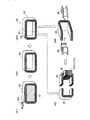
また、第1曲げコア7と第2曲げコア15の作製は、先ず、図3(B1)に示すように、断面略長四角形の芯部材17に長手方向(図3(B1)中、矢印18A方向)に磁化容易方向を有する長尺状の方向性電磁鋼板18(第3電磁鋼板として機能する。)を所定回数巻きつける。また、この芯部材17の断面の長辺部の長さは、ティース部5の半径方向の長さ寸法とロータティース部11の半径方向の長さ寸法との合計寸法にほぼ等しい寸法に形成されている。また、この方向性電磁鋼板18の幅寸法は、ティース部5及びロータティース部11の各周方向幅寸法に等しく形成されている。
そして、図3(B2)に示すように、芯部材17を抜き去り、ワニス等で固めて巻コア部材19を形成する(第3工程)。
続いて、図3(B3)に示すように、巻コア部材19の内側貫通孔の長辺部をティース部5の半径方向の長さ寸法とロータティース部11の半径方向の長さ寸法とにほぼ等しくなるように分割する切断位置21で巻方向に対して略垂直に切断して、第1曲げコア7と第2曲げコア15とに分割形成する(第4工程)。
First, as shown in FIG. 3 (B1), first, as shown in FIG. 3 (B1), the first
Then, as shown in FIG. 3 (B2), the
Subsequently, as shown in FIG. 3 (B3), the long side of the inner through-hole of the
その後、図3(C)に示すように、ステータ6の各ティース部5の軸方向上下端面部に各第1曲げコア7を切断面が半径方向内側を向くように積層し、プリプレグ(ガラス繊維状接着シート)22で巻回後所定温度に加熱してこのプリプレグ22を溶融して積層・接着する(第5工程)。
また、ロータ12の各ロータティース部11の軸方向上下端面部に各第2曲げコア15を切断面が半径方向外側を向くように積層し、プリプレグ(ガラス繊維状接着シート)23で巻回後所定温度に加熱してこのプリプレグ23を溶融して積層・接着する(第6工程)。これにより、回転子3が形成される。
Then, as shown in FIG. 3C, the
Further, the second
そして、図3(D)に示すように、各固定子コイル8A〜8Cの巻回されるボビン9をステータ6の各ティース部5とこのティース部5に積層・接着される各第1曲げコア7の内側面に半径方向内側から挿入して装着する(第7工程)。これにより、固定子2が形成される。
Then, as shown in FIG. 3 (D), the
次に、上記製造方法により作製された三相同期モータ1の各固定子コイル8A〜8Cに順次通電して励磁した場合に形成される磁気回路について図1及び図2に基づいて説明する。
尚、図1及び図2には各固定子コイル8Aに通電して励磁した場合に、固定子2と回転子3に形成される磁気回路が示されているが、各固定子コイル8B、8Cにそれぞれ通電した場合にも固定子2と回転子3に同様な磁気回路が形成される。
図1及び図2に示すように、各固定子コイル8Aに通電することにより、この固定子コイル8Aが巻回される各ティース部5内とこのティース部5に積層・固着される各第1曲げコア7の固着側内に半径方向に流れる磁束が発生する。
Next, a magnetic circuit formed when the stator coils 8A to 8C of the three-phase
FIGS. 1 and 2 show magnetic circuits formed in the
As shown in FIGS. 1 and 2, when current is applied to each stator coil 8 </ b> A, each of the
そして、無方向性電磁鋼板を複数枚積層して形成されるステータ6の各ティース部5内に発生した半径方向外側に流れる磁束は、各ティース部5の基端部で周方向に約90度曲げられてステータ6のヨーク部内を流れる。
続いて、ステータ6のヨーク部内を流れる磁束は、直交する位置の各固定子コイル8Aにより、該固定子コイル8Aが巻回されるティース部5の基端部で再度、約90度曲げられてこのティース部5内を半径方向内側に流れ、対向配置されるロータティース部11内を半径方向内側に流れる。そして、このロータティース部11内に発生した半径方向内側に流れる磁束は、各ロータティース部11の基端部で周方向に約90度曲げられて無方向性電磁鋼板を複数枚積層して形成されるロータ12内を流れる。そしてまた、ロータ12内を周方向に流れる磁束は、直交する位置の各ロータティース部11の基端部で再度、約90度曲げられてこのロータティース部11内を半径方向外側に流れ、対向配置されるティース部5内を半径方向外側に流れる。
これにより、図1に示すように、無方向性電磁鋼板を複数枚、積層・固着して形成されるステータ6とロータ12内を流れる4つの磁気閉回路(図1(A)中、太実線で示す磁気閉回路)25が形成される。
The magnetic flux generated in each
Subsequently, the magnetic flux flowing in the yoke portion of the
As a result, as shown in FIG. 1, a plurality of non-oriented electrical steel sheets are stacked and fixed, and four magnetic closed circuits flowing in the
また、固定子コイル8Aへの通電によって各ティース部5に積層・固着される各第1曲げコア7の固着側内に発生した磁束は、図1(B)に示すように、半径方向外側に流れる場合には、方向性電磁鋼板18を複数枚、積層して形成される第1曲げコア7の磁化容易方向、即ち、曲げ方向に沿って流れ、軸方向外側の切断面まで流れて、この第1曲げコア7に対向配置される第2曲げコア15内に流れ込む。そして、この第2曲げコア15内に流れ込んだ磁束は、方向性電磁鋼板18を複数枚、積層して形成される第2曲げコア15の磁化容易方向、即ち、曲げ方向に沿って流れ、第2曲げコア15の固着側の切断面まで流れて、対向配置される第1曲げコア7の固着側切断面に流れる。
一方、固定子コイル8Aへの通電によって各ティース部5に積層・固着される各第1曲げコア7の固着側内に発生した磁束が、半径方向内側に流れる場合には、各第1曲げコア7と各第2曲げコア15内には、図1(B)に示す磁束の流れと反対方向に磁束が流れる。
これにより、図1に示すように、各ティース部5とロータティース部11の軸方向上下端面部に積層・固着されて、対向配置される各第1曲げコア7と第2曲げコア15内を流れる8個の磁気閉回路(図1(A)中、破線で示す磁気閉回路)26が形成される。
Further, the magnetic flux generated in the fixed side of each
On the other hand, when the magnetic flux generated in the fixed side of each of the first
As a result, as shown in FIG. 1, the inside of each of the
従って、第1実施形態に係る三相同期モータ1は、各固定子コイル8A〜8Cが順番に通電されて、各ティース部5とロータティース部11とが対向した場合には、対向配置される各第1曲げコア7と第2曲げコア15とによって磁気閉回路26が形成されるため、磁路長を短くでき、低鉄損化を図ることができる。また、各第1曲げコア7及び第2曲げコア15は、曲げ方向に沿った磁化容易方向を有する方向性電磁鋼板18により形成されるため、各第1曲げコア7と第2曲げコア15とが無方向性電磁鋼板により構成されている場合よりも更なる低鉄損化を図ることができ、また、トルクの更なる向上を図ることができる。
Therefore, in the three-phase
また、各ティース部5の軸方向厚さ寸法を軸方向上下端面部に固着される各第1曲げコア7の軸方向厚さ寸法分ずつ短くしても、従来のティース部の磁路断面積と同一の磁路断面積を得ることができるため、各第1曲げコア7間のヨーク部を無くすことができ、三相同期モータ1の軽量化を図ることができる。また、各固定子コイル8A〜8Cが各ティース部5の両側面部と上下各第1曲げコア7の内側面に巻回されるため、この各固定子コイル8A〜8Cの軸方向の巻長さを左右側面部において、各第1曲げコア7の軸方向厚さ寸法分ずつ短くして巻回することができ、三相同期モータ1の軽量化を図ることができる。また、同様に、各ロータティース部11の軸方向厚さ寸法を軸方向上下端面部に固着される各第2曲げコア15の軸方向厚さ寸法分ずつ短くしても、従来のロータティース部の磁路断面積と同一の磁路断面積を得ることができるため、各第2曲げコア15間のロータ部を無くすことができ、三相同期モータ1の軽量化を図ることができる。
Even if the axial thickness of each
また、三相同期モータ1の各第1曲げコア7と第2曲げコア15とは、断面略長四角形の芯部材17に長尺状の方向性電磁鋼板18を所定回数巻回後、この芯部材17を取り除き、該方向性電磁鋼板18を固着して巻コア部材19を形成した後、この巻コア部材19を内側貫通孔の長辺方向の所定箇所で巻回方向に対して略垂直に切断することにより作製できるため、各第1曲げコア7と第2曲げコア15を容易に作製することができる。また、各第1曲げコア7を各ティース部5の軸方向の上下各端面部に切断面が半径方向内側へ向くように積層・固着し、各固定子コイル8A〜8Cをティース部5の周方向両側面及び該ティース部5に積層・固着される各第1曲げコア7の内側面に巻装することによって固定子2を形成できるため、該固定子2を容易に製造することができる。また、各第2曲げコア15を各ロータティース部11の軸方向の上下各端面部に切断面が半径方向外側へ向くように積層・固着することにより回転子3を形成できるため、該回転子3を容易に製造することができる。更に、ステータ6とロータ12との製造に従来のステータとロータとを作製する製造設備を使用することが可能なため、製造コストの削減化を図ることができる。
更に、各第1曲げコア7と第2曲げコア15は、長手方向に磁化容易方向を有する長尺状の方向性電磁鋼板18により作製される巻きコア部材19を所定切断位置で切断して形成されるため、曲げ方向に磁化容易方向を有して大きく低鉄損化を図ることができる第1曲げコア7及び第2曲げコア15を同時に製造することができる。
The first
Furthermore, each of the first
次に、第2実施形態に係る三相同期モータについて図4乃至図6に基づいて説明する。尚、上記第1実施形態に係る三相同期モータ1と同一符号は、上記第1実施形態に係る三相同期モータ1と同一あるいは相当部分を示すものである。
この第2実施形態に係る三相同期モータの全体構成は、第1実施形態に係る三相同期モータ1の全体構成とほぼ同じ構成である。但し、各ティース部5の軸方向上下端面部に固着される各第1曲げコアと各ロータティース部11の軸方向上下端面部に固着される各第2曲げコアの構成が上記第1実施形態に係る三相同期モータ1と異なっている。
Next, a three-phase synchronous motor according to a second embodiment will be described with reference to FIGS. The same reference numerals as those of the three-phase
The overall configuration of the three-phase synchronous motor according to the second embodiment is substantially the same as the overall configuration of the three-phase
先ず、第2実施形態に係る三相同期モータの概略構成について図4に基づき説明する。
図4に示すように、第2実施形態に係る三相同期モータ31は、固定子32と回転子33とこれらを収納する不図示のケースとから構成されている。
固定子32は、上記第1実施形態に係る固定子2とほぼ同じ構成であるが、各ティース部5の軸方向上下端面部には、24個の断面略横長コの字形の第1曲げコア35が、折曲先端部を半径方向内側向きして積層・固着されている。この各第1曲げコア35の周方向幅寸法は、ティース部5の周方向幅寸法にほぼ等しく形成されている。また、この各第1曲げコア35の各折曲先端面は、各ティース部5の内周面と同一面上に配置されると共に、各第1曲げコア35は、各ティース部5の基端部より半径方向外側の位置で略横長コの字形に半径方向内側向きに折り曲げられ、この折曲後端部の外周部に巻装される樹脂製ボビン36に各曲げコア部コイル37A、37B、37Cが、各ティース部5毎に順番に巻回されている。また、各ティース部5の周方向両側面及びこのティース部5の上下端面部に固着される各第1曲げコア35の内側面に巻装される樹脂製ボビン9に各固定子コイル8A、8B、8Cが順番に巻回されている。尚、各第1曲げコア35は、望ましくは、ステータ6のヨーク部外周部分の半径方向略中央位置に折曲後端部が位置するように構成されているのが望ましい。これにより、各曲げコア部コイル37A〜37Cの巻回数を容易に増加させることができる。
First, a schematic configuration of the three-phase synchronous motor according to the second embodiment will be described with reference to FIG.
As shown in FIG. 4, a three-phase
The
また、回転子33は、上記第1実施形態に係る回転子3とほぼ同じ構成であるが、各ロータティース部11の軸方向上下端面部には、16個の断面略コの字形の第2曲げコア39が、折曲先端部を半径方向外側向きにして固着されている。この各第2曲げコア39の周方向幅寸法は、ロータティース部11の周方向幅寸法にほぼ等しく形成されている。また、各第2曲げコア39の各折曲先端面は、各ロータティース部11の内周面と同一面上に配置されると共に、各第2曲げコア39は各ロータティース部11の基端部で略コの字形に半径方向外側向きに折り曲げられている。
The
ここで、三相同期モータ31の固定子32及び回転子33の製造方法について図5及び図6に基づいて説明する。尚、三相同期モータ31の製造方法は、第1実施形態に係る三相同期モータ1の製造方法とほぼ同じであるが、後述のように各曲げコア部コイル37A〜37Cが巻回された第1曲げコア35を各ティース部5の軸方向上下端面部に固着する点で異なっている。従って、ステータ6の作製工程(第1工程)とロータ12の作製工程(第2工程)とは、上記第1実施形態に係る各作製工程とほぼ同じ製造方法である。
先ず、各曲げコア部コイル37A〜37Cを巻回した第1曲げコア35及び第2曲げコア39の製造方法について図5に基づいて説明する。
(第3工程)
この第1曲げコア35と第2曲げコア39の作製は、最初に、図5(A1)に示すように、断面横長四角形の芯部材41に長手方向(図5(A1)中、矢印18A方向)に磁化容易方向を有する長尺状の方向性電磁鋼板18を所定回数巻きつける。また、この芯部材41の断面の長辺部の長さは、ティース部5の先端部からヨーク部の半径方向略中央位置までの長さ寸法とロータティース部11の半径方向の長さ寸法との合計寸法にほぼ等しい寸法に形成されている。また、この方向性電磁鋼板18の幅寸法は、ティース部5及びロータティース部11の各周方向幅寸法に等しく形成されている。
そして、図5(A2)に示すように、芯部材41を抜き去り、ワニス等で固めて巻コア部材42を形成する。
Here, a method of manufacturing the
First, a method of manufacturing the first
(3rd step)
First, as shown in FIG. 5 (A1), the first
Then, as shown in FIG. 5 (A2), the
(第4工程)
続いて、図5(A3)に示すように、巻コア部材42の内側貫通孔の長辺部を一方の短辺部からロータティース部11の半径方向の長さ寸法にほぼ等しくなる切断位置43で巻方向に対して略垂直に切断して、第1曲げコア35と第2曲げコア39とに分割形成する。
その後、図5(A4)に示すように、第1曲げコア35の折曲後端部の両側端縁部に水平断面略コの字状に二分割した樹脂製ボビン36を嵌挿して、巻装・固着する。
そして、図5(A5)に示すように、このボビン36に各曲げコア部コイル37A〜37Cを巻回する。これにより、各曲げコア部コイル37A〜37Cを巻回した第1曲げコア35及び第2曲げコア39が作製される。尚、各第1曲げコア35の折曲先端部から各曲げコア部コイル37A〜37Cの折曲先端側の端面部までの距離寸法は、ほぼティース部5の半径方向長さ寸法にほぼ等しくなるように形成されている。
(4th process)
Subsequently, as shown in FIG. 5 (A3), the long side portion of the inner through hole of the
Thereafter, as shown in FIG. 5 (A4), a
Then, as shown in FIG. 5 (A5), each of the bent core portion coils 37A to 37C is wound around the
続いて、三相同期モータ31の固定子32と回転子33の作製工程について図6に基づいて説明する。
(第5工程)
図6(A)に示すように、ステータ6の各ティース部5の軸方向上下端面部に各第1曲げコア35を切断面が半径方向内側を向くように積層し、プリプレグ(ガラス繊維状接着シート)45で巻回後所定温度に加熱してこのプリプレグ45を溶融して積層・接着する。
(第6工程)
また、ロータ12の各ロータティース部11の軸方向上下端面部に各第2曲げコア39を切断面が半径方向外側を向くように積層し、プリプレグ(ガラス繊維状接着シート)46で巻回後所定温度に加熱してこのプリプレグ46を溶融して積層・接着する。これにより、回転子33が形成される。
(第7工程)
そして、図6(B)に示すように、各固定子コイル8A〜8Cの巻回されるボビン9をステータ6の各ティース部5とこのティース部5に積層・接着される各第1曲げコア35の内側面に半径方向内側から挿入して装着する。これにより、固定子32が形成される。
Next, a process of manufacturing the
(Fifth step)
As shown in FIG. 6 (A), the
(Sixth step)
Further, the second
(Seventh step)
Then, as shown in FIG. 6 (B), the
次に、上記製造方法により作製された三相同期モータ31の各固定子コイル8A〜8C及び各曲げコア部コイル37A〜37Cに順次通電して励磁した場合に形成される磁気回路について図4に基づいて説明する。
尚、図4には各固定子コイル8A及び各曲げコア部コイル37Aに通電して励磁した場合に、固定子32と回転子33に形成される磁気回路が示されているが、各固定子コイル8B、8C及び各曲げコア部コイル37B、37Cにそれぞれ通電した場合にも固定子32と回転子33に同様な磁気回路が形成される。
図4に示すように、各固定子コイル8Aに通電することにより、この固定子コイル8Aが巻回される各ティース部5内に流れる(矢印51方向に流れる)磁束とこのティース部5に積層・固着される各第1曲げコア35の固着側内に半径方向に流れる(各矢印52方向に流れる)磁束が発生する。また、各曲げコア部コイル37Aに通電することにより、この曲げコア部コイル37Aが巻回される第1曲げコア35の折曲後端部内に軸方向外側に向かって流れる(各矢印53方向に流れる)磁束が発生する。
Next, FIG. 4 shows a magnetic circuit formed when the stator coils 8A to 8C and the
FIG. 4 shows a magnetic circuit formed on the
As shown in FIG. 4, when the
そして、無方向性電磁鋼板を複数枚積層して形成されるステータ6の各ティース部5内に発生した半径方向外側に流れる磁束は、各ティース部5の基端部で周方向に約90度曲げられてステータ6のヨーク部内を流れる。
続いて、ステータ6のヨーク部内を流れる磁束は、直交する位置の各固定子コイル8Aにより、該固定子コイル8Aが巻回されるティース部5の基端部で再度、約90度曲げられてこのティース部5内を半径方向内側に流れ、対向配置されるロータティース部11内を半径方向内側に流れる。そして、このロータティース部11内に発生した半径方向内側に流れる磁束は、各ロータティース部11の基端部で周方向に約90度曲げられて無方向性電磁鋼板を複数枚積層して形成されるロータ12内を流れる。そしてまた、ロータ12内を周方向に流れる磁束は、直交する位置の各ロータティース部11の基端部で再度、約90度曲げられてこのロータティース部11内を半径方向外側に流れ、対向配置されるティース部5内を半径方向外側に流れる。
これにより、図4(A)に示すように、無方向性電磁鋼板を複数枚、積層・固着して形成されるステータ6とロータ12内を流れる4つの磁気閉回路(図4(A)中、太実線で示す磁気閉回路)25が形成される。
The magnetic flux generated in each
Subsequently, the magnetic flux flowing in the yoke portion of the
As a result, as shown in FIG. 4A, a plurality of non-oriented electrical steel sheets are stacked and fixed, and four magnetic closed circuits flowing in the
また、図4(B)に示すように、固定子コイル8Aと各曲げコア部コイル37Aとの通電によって各ティース部5に積層・固着される各第1曲げコア35内に発生した磁束は、共に方向性電磁鋼板18を複数枚、積層して形成される各第1曲げコア35の磁化容易方向、即ち、曲げ方向に沿って流れる(図4(B)中、各第1曲げコア35の上下外側の折曲部内の各矢印52、53方向に流れる)。そして、各第1曲げコア35のティース部5への固着側に相対する他方の折曲部内を半径方向内側に流れた磁束は、該各第1曲げコア35の軸方向外側の切断面まで流れて、対向配置される各第2曲げコア39内に流れ込む。そして、この第2曲げコア39内に流れ込んだ磁束は、方向性電磁鋼板18を複数枚、積層して形成される第2曲げコア39の磁化容易方向、即ち、曲げ方向に沿って流れ(各矢印55、56、57方向に流れ)、第2曲げコア39の固着側の切断面まで流れて、対向配置される各第1曲げコア35の固着側切断面に流れる。
Further, as shown in FIG. 4B, the magnetic flux generated in each
一方、固定子コイル8Aへの通電によって各ティース部5に積層・固着される各第1曲げコア35の固着側内に発生した磁束が、半径方向内側に流れる場合には、該固定子コイル8Aが巻回される各第1曲げコア35に巻回された各曲げコア部コイル37Aは、軸方向内側に流れる磁束が発生するように通電される。そして、固定子コイル8Aと各曲げコア部コイル37Aとの通電によって各第1曲げコア35内に発生した磁束は、共に図4(B)に示す磁束の流れと反対方向に(図4(B)中、各矢印52〜57方向と反対方向に)流れる。
これにより、図4に示すように、各ティース部5とロータティース部11の軸方向上下端面部に積層・固着されて、対向配置される各第1曲げコア35と第2曲げコア39内を流れる8個の磁気閉回路(図4(A)中、破線で示す磁気閉回路)59が形成される。
On the other hand, when the magnetic flux generated in the fixed side of each of the
As a result, as shown in FIG. 4, the inside of each of the
従って、第2実施形態に係る三相同期モータ31は、各固定子コイル8A〜8C及び各曲げコア部コイル37A〜37Cが順番に通電されて、各ティース部5とロータティース部11とが対向した場合には、対向配置される各第1曲げコア35と第2曲げコア39内には、各固定子コイル8A〜8C及び各曲げコア部コイル37A〜37Cの通電によって発生した磁束が共に流れて、該各第1曲げコア35と第2曲げコア39内を流れる磁束量を大幅に増大させることができ、各第1曲げコア35に対向配置される第2曲げコア39と協働して形成される磁路長の短い磁気閉回路59が形成される効果と相まって、低鉄損化を図ると共に、更なる高トルク化及び高効率化を図ることができる。
また、各第1曲げコア35及び第2曲げコア39は、曲げ方向に沿った磁化容易方向を有する方向性電磁鋼板18により形成されるため、各第1曲げコア35と第2曲げコア39とが無方向性電磁鋼板により構成されている場合よりも更なる低鉄損化を図ることができ、また、トルクの更なる向上を図ることができる。
Therefore, in the three-phase
Further, since each of the first
また、各ティース部5の軸方向厚さ寸法を軸方向上下端面部に固着される各第1曲げコア35の軸方向厚さ寸法分ずつ短くしても、従来のティース部の磁路断面積と同一の磁路断面積を得ることができるため、各第1曲げコア35間のヨーク部を無くすことができ、三相同期モータ31の軽量化を図ることができる。また、各固定子コイル8A〜8Cが各ティース部5の両側面部と上下各第1曲げコア35の内側面に巻回されるため、この各固定子コイル8A〜8Cの軸方向の巻長さを左右側面部において、各第1曲げコア35の軸方向厚さ寸法分ずつ短くして巻回することができ、三相同期モータ31の軽量化を図ることができる。また、同様に、各ロータティース部11の軸方向厚さ寸法を軸方向上下端面部に固着される各第2曲げコア39の軸方向厚さ寸法分ずつ短くしても、従来のロータティース部の磁路断面積と同一の磁路断面積を得ることができるため、各第2曲げコア39間のロータ部を無くすことができ、三相同期モータ31の軽量化を図ることができる。
また、各第1曲げコア35の折曲後端部の外周部に曲げコア部コイル37A〜37Cを巻回して、該各第1曲げコア35の折曲先端部を半径方向内側向きにティース部5の軸方向上下端面部に固着できるため、各第1曲げコア35の軸方向高さ寸法の増加を防止して、三相同期モータ31の薄型化を図りつつ、更なる高トルク化及び高効率化を図ることができる。
Further, even if the axial thickness of each
In addition, the bent core portion coils 37A to 37C are wound around the outer peripheral portion of the bent rear end portion of each first
また、三相同期モータ31の各第1曲げコア35と第2曲げコア39とは、断面長四角形の芯部材41に長尺状の方向性電磁鋼板18を所定回数巻回後、この芯部材41を取り除き、該方向性電磁鋼板18を固着して巻コア部材42を形成した後、この巻コア部材42を内側貫通孔の長辺方向の所定箇所で巻回方向に対して略垂直に切断することにより作製できるため、各第1曲げコア35と第2曲げコア39を容易に作製することができる。また、各第1曲げコア35に曲げコア部コイル37A〜37Cを予め巻回後、該第1曲げコア35を各ティース部5の軸方向の上下各端面部に切断面が半径方向内側へ向くように積層・固着し、各固定子コイル8A〜8Cをティース部5の周方向両側面及び該ティース部5に積層・固着される各第1曲げコア35の内側面に巻装することによって固定子32を形成できるため、該固定子32を容易に製造することができると共に、組み立て作業の迅速化及び製造コストの削減化を図ることができる。また、巻きコア部材42を所定切断位置43で分割して第1曲げコア35を分割形成後、この第1曲げコア35の折曲後端部の外周部に、ボビン36を巻装して各曲げコア部コイル37A〜37Cを巻回するため、各第1曲げコア35の相対向する各折曲部を把持して、該折曲後端部に各曲げコア部コイル37A〜37Cを容易に巻回することができ、該各曲げコア部コイル37A〜37Cの巻回作業の迅速化及び製造コストの削減化を図ることができる。
また、各第2曲げコア39を各ロータティース部11の軸方向の上下各端面部に切断面が半径方向外側へ向くように積層・固着することにより回転子33を形成できるため、該回転子33を容易に製造することができる。更に、ステータ6とロータ12との製造に従来のステータとロータとを作製する製造設備を使用することが可能なため、製造コストの削減化を図ることができる。
更に、各第1曲げコア35と第2曲げコア39は、長手方向に磁化容易方向を有する長尺状の方向性電磁鋼板18により作製される巻きコア部材42を所定切断位置で切断して形成されるため、曲げ方向に磁化容易方向を有して大きく低鉄損化を図ることができる第1曲げコア35及び第2曲げコア39を同時に製造することができる。
The first
Further, the
Further, each of the first
次に、第3実施形態に係る三相同期モータについて図7及び図8に基づいて説明する。尚、上記第2実施形態に係る三相同期モータ31と同一符号は、上記第2実施形態に係る三相同期モータ31と同一あるいは相当部分を示すものである。
この第3実施形態に係る三相同期モータの全体構成は、第2実施形態に係る三相同期モータ31の全体構成とほぼ同じ構成である。但し、各ティース部5の軸方向上下端面部に固着される各第1曲げコアの構成が上記第2実施形態に係る三相同期モータ31と異なっている。
Next, a three-phase synchronous motor according to a third embodiment will be described with reference to FIGS. The same reference numerals as those of the three-phase
The overall configuration of the three-phase synchronous motor according to the third embodiment is substantially the same as the overall configuration of the three-phase
先ず、第3実施形態に係る三相同期モータの概略構成について図7に基づき説明する。
図7に示すように、第3実施形態に係る三相同期モータ61は、固定子62と回転子63とこれらを収納する不図示のケースとから構成されている。
固定子62は、上記第2実施形態に係る固定子32とほぼ同じ構成であるが、各ティース部5の軸方向上下端面部には、上記第2実施形態に係る第1曲げコア35と同様に方向性電磁鋼板18により作製された24個の断面略コの字形の第1曲げコア65が、折曲先端部を半径方向内側向きして積層・固着されている。この各第1曲げコア65の周方向幅寸法は、ティース部5の周方向幅寸法にほぼ等しく形成されている。また、この各第1曲げコア65の各折曲先端面は、各ティース部5の内周面と同一面上に配置されている。また、各第1曲げコア65は、各ティース部5の基端部より断面略コの字形に半径方向内側向きに折り曲げられ、この各第1曲げコア65のティース部5への固着側に相対する他方の折曲部の外周部に巻装される各樹脂製ボビン66に各曲げコア部コイル37A、37B、37Cが、各ティース部5毎に順番に巻回されている。また、各ティース部5の周方向両側面及びこのティース部5の上下端面部に固着される各第1曲げコア65の内側面に巻装される樹脂製ボビン9に各固定子コイル8A、8B、8Cが順番に巻回されている。
First, a schematic configuration of the three-phase synchronous motor according to the third embodiment will be described with reference to FIG.
As shown in FIG. 7, the three-phase
The
また、回転子63は、上記第2実施形態に係る回転子33とほぼ同じ構成で、各ロータティース部11の軸方向上下端面部には、上記第2実施形態に係る第2曲げコア39と同様に方向性電磁鋼板18により作製された16個の断面略コの字形の第2曲げコア68が、折曲先端部を半径方向外側向きにして固着されている。この各第2曲げコア68の周方向幅寸法は、ロータティース部11の周方向幅寸法にほぼ等しく形成されている。また、各第2曲げコア68の各折曲先端面は、各ロータティース部11の内周面と同一面上に配置されると共に、各第2曲げコア68は各ロータティース部11の基端部で略コの字形に半径方向外側向きに折り曲げられている。
The
次に、三相同期モータ61の固定子62製造方法について図8に基づいて説明する。尚、三相同期モータ61の製造方法は、第2実施形態に係る三相同期モータ31の製造方法とほぼ同じであるが、後述のように各曲げコア部コイル37A〜37Cを第1曲げコア65のティース部5への固着側に相対する他方の折曲部の外周部にボビン66を介して巻回している点で異なっている。
ここで、ステータ6の作製工程(第1工程)とロータ12の作製工程(第2工程)とは、上記第2実施形態に係る各作製工程とほぼ同じ製造方法である。
(第3工程)
また、上記第2実施形態に係る芯部材41に替えて長辺部の長さ寸法が、ティース部5の半径方向の長さ寸法とロータティース部11の半径方向の長さ寸法との合計寸法にほぼ等しい寸法に形成された断面四角形の芯部材に長尺状の方向性電磁鋼板18を所定回数巻きつけて巻きコア部材を作製する。
(第4工程)
そして、この巻きコア部材の内側貫通孔の長辺部を一方の短辺部からロータティース部11の半径方向の長さ寸法にほぼ等しくなる切断位置で巻方向に対して略垂直に切断して、第1曲げコア65と第2曲げコア68とに分割形成する。
そして、図8(A)に示すように、各第1曲げコア65の一方の折曲部に樹脂製ボビン66を嵌挿して、巻装・固着する。そして、このボビン66に各曲げコア部コイル37A〜37Cを巻回する。これにより、各曲げコア部コイル37A〜37Cを巻回した第1曲げコア65及び第2曲げコア68が作製される。
Next, a method of manufacturing the
Here, the manufacturing process of the stator 6 (first process) and the manufacturing process of the rotor 12 (second process) are almost the same manufacturing method as each manufacturing process according to the second embodiment.
(3rd step)
In addition, the length of the long side portion is replaced by the
(4th process)
Then, the long side of the inner through hole of the wound core member is cut substantially perpendicularly to the winding direction from one short side at a cutting position where the length in the radial direction of the
Then, as shown in FIG. 8A, a
(第5工程)
そして、図8に示すように、三相同期モータ61の固定子62は、先ず、ステータ6の各ティース部5の軸方向上下端面部に、各曲げコア部コイル37A〜37Cが巻回された第1曲げコア65を該各曲げコア部コイル37A〜37Cが軸方向外側に位置し、且つ各第1曲げコア65の切断面が半径方向内側を向くように積層し、プリプレグ(ガラス繊維状接着シート)45で巻回後所定温度に加熱してこのプリプレグ45を溶融して積層・固着する。
(第6工程)
また、三相同期モータ61の回転子63は、上記第2実施形態に係る回転子33と同様に作製され、ロータ12の各ロータティース部11の軸方向上下端面部に各第2曲げコア68を切断面が半径方向外側を向くように積層し、プリプレグ(ガラス繊維状接着シート)46で巻回後所定温度に加熱してこのプリプレグ46を溶融して積層・固着することにより作製される。
(第7工程)
そして、図8(B)に示すように、各固定子コイル8A〜8Cの巻回されるボビン9をステータ6の各ティース部5とこのティース部5に積層・接着される各第1曲げコア65の内側面に半径方向内側から挿入して装着する。これにより、固定子62が形成される。
(Fifth step)
Then, as shown in FIG. 8, in the
(Sixth step)
The
(Seventh step)
Then, as shown in FIG. 8B, the
次に、上記製造方法により作製された三相同期モータ61の各固定子コイル8A〜8C及び各曲げコア部コイル37A〜37Cに順次通電して励磁した場合に形成される磁気回路について図7に基づいて説明する。
尚、図7には各固定子コイル8A及び各曲げコア部コイル37Aに通電して励磁した場合に、固定子62と回転子63に形成される磁気回路が示されているが、各固定子コイル8B、8C及び各曲げコア部コイル37B、37Cにそれぞれ通電した場合にも固定子62と回転子63に同様な磁気回路が形成される。
図7に示すように、各固定子コイル8Aに通電することにより、この固定子コイル8Aが巻回される各ティース部5内に流れる(矢印71方向に流れる)磁束とこのティース部5に積層・固着される各第1曲げコア65の固着側内に半径方向に流れる(各矢印72方向に流れる)磁束が発生する。また、各曲げコア部コイル37Aに通電することにより、この曲げコア部コイル37Aが巻回される第1曲げコア65の折曲部内に半径方向内側に向かって流れる(各矢印73方向に流れる)磁束が発生する。
Next, FIG. 7 shows a magnetic circuit formed when the stator coils 8A to 8C and the
FIG. 7 shows a magnetic circuit formed on the
As shown in FIG. 7, when the
そして、無方向性電磁鋼板を複数枚積層して形成されるステータ6の各ティース部5内に発生した半径方向外側に流れる磁束は、各ティース部5の基端部で周方向に約90度曲げられてステータ6のヨーク部内を流れる。
続いて、ステータ6のヨーク部内を流れる磁束は、直交する位置の各固定子コイル8Aにより、該固定子コイル8Aが巻回されるティース部5の基端部で再度、約90度曲げられてこのティース部5内を半径方向内側に流れ、対向配置されるロータティース部11内を半径方向内側に流れる。そして、このロータティース部11内に発生した半径方向内側に流れる磁束は、各ロータティース部11の基端部で周方向に約90度曲げられて無方向性電磁鋼板を複数枚積層して形成されるロータ12内を流れる。そしてまた、ロータ12内を周方向に流れる磁束は、直交する位置の各ロータティース部11の基端部で再度、約90度曲げられてこのロータティース部11内を半径方向外側に流れ、対向配置されるティース部5内を半径方向外側に流れる。
これにより、図7(A)に示すように、無方向性電磁鋼板を複数枚、積層・固着して形成されるステータ6とロータ12内を流れる4つの磁気閉回路(図7(A)中、太実線で示す磁気閉回路)25が形成される。
The magnetic flux generated in each
Subsequently, the magnetic flux flowing in the yoke portion of the
As a result, as shown in FIG. 7A, a plurality of non-oriented electrical steel sheets are stacked and fixed, and four magnetic closed circuits flowing in the
また、図7(B)に示すように、固定子コイル8Aと各曲げコア部コイル37Aとの通電によって各ティース部5に積層・固着される各第1曲げコア65内に発生した磁束は、共に方向性電磁鋼板18を複数枚、積層して形成される各第1曲げコア65の磁化容易方向、即ち、曲げ方向に沿って流れる(図7(B)中、各矢印72、73方向に流れる)。そして、各第1曲げコア65を流れた磁束は、該各第1曲げコア65の軸方向外側の切断面まで流れて、対向配置される各第2曲げコア68内に流れ込む。そして、この第2曲げコア68内に流れ込んだ磁束は、方向性電磁鋼板18を複数枚、積層して形成される第2曲げコア68の磁化容易方向、即ち、曲げ方向に沿って流れ(各矢印74、75、76方向に流れ)、第2曲げコア68の固着側の切断面まで流れて、対向配置される各第1曲げコア65の固着側切断面に流れる。
Further, as shown in FIG. 7B, the magnetic flux generated in each
一方、固定子コイル8Aへの通電によって各ティース部5に積層・固着される各第1曲げコア65の固着側内に発生した磁束が、半径方向内側に流れる場合には、該固定子コイル8Aが巻回される各第1曲げコア65に巻回された各曲げコア部コイル37Aは、この曲げコア部コイル37Aが巻回される第1曲げコア65の折曲部内に半径方向外側に向かって流れる磁束が発生するように通電される。そして、固定子コイル8Aと各曲げコア部コイル37Aとの通電によって各第1曲げコア65内に発生した磁束は、共に図7(B)に示す磁束の流れと反対方向に(図7(B)中、各矢印72〜76方向と反対方向に)流れる。
これにより、図7に示すように、各ティース部5とロータティース部11の軸方向上下端面部に積層・固着されて、対向配置される各第1曲げコア65と第2曲げコア68内を流れる8個の磁気閉回路(図7(A)中、破線で示す磁気閉回路)78が形成される。
On the other hand, when the magnetic flux generated in the fixed side of each of the
As a result, as shown in FIG. 7, the
従って、第3実施形態に係る三相同期モータ61は、各固定子コイル8A〜8C及び各曲げコア部コイル37A〜37Cが順番に通電されて、各ティース部5とロータティース部11とが対向した場合には、対向配置される各第1曲げコア65と第2曲げコア68内には、各固定子コイル8A〜8C及び各曲げコア部コイル37A〜37Cの通電によって発生した磁束が共に流れて、該各第1曲げコア65と第2曲げコア68内を流れる磁束量を大幅に増大させることができ、各第1曲げコア65に対向配置される第2曲げコア68と協働して形成される磁路長の短い磁気閉回路78が形成される効果と相まって、低鉄損化を図ると共に、更なる高トルク化及び高効率化を図ることができる。
また、各第1曲げコア65及び第2曲げコア68は、曲げ方向に沿った磁化容易方向を有する方向性電磁鋼板18により形成されるため、各第1曲げコア65と第2曲げコア68とが無方向性電磁鋼板により構成されている場合よりも更なる低鉄損化を図ることができ、また、トルクの更なる向上を図ることができる。
Therefore, in the three-phase
Further, since each of the
また、各ティース部5の軸方向厚さ寸法を軸方向上下端面部に固着される各第1曲げコア65の軸方向厚さ寸法分ずつ短くしても、従来のティース部の磁路断面積と同一の磁路断面積を得ることができるため、各第1曲げコア65間のヨーク部を無くすことができ、三相同期モータ61の軽量化を図ることができる。また、各固定子コイル8A〜8Cが各ティース部5の両側面部と上下各第1曲げコア65の内側面に巻回されるため、この各固定子コイル8A〜8Cの軸方向の巻長さを左右側面部において、各第1曲げコア65の軸方向厚さ寸法分ずつ短くして巻回することができ、三相同期モータ61の軽量化を図ることができる。また、同様に、各ロータティース部11の軸方向厚さ寸法を軸方向上下端面部に固着される各第2曲げコア68の軸方向厚さ寸法分ずつ短くしても、従来のロータティース部の磁路断面積と同一の磁路断面積を得ることができるため、各第2曲げコア68間のロータ部を無くすことができ、三相同期モータ61の軽量化を図ることができる。
また、各第1曲げコア65の軸方向外側の折曲部の外周部に曲げコア部コイル37A〜37Cを巻回して、該各第1曲げコア65の折曲先端部を半径方向内側向きにティース部5の軸方向上下端面部に固着できるため、各第1曲げコア65の外径寸法の増加を防止して、三相同期モータ61の細径化を図りつつ、更なる高トルク化及び高効率化を図ることができる。
Even if the axial thickness of each
In addition, the bending core portion coils 37A to 37C are wound around the outer peripheral portion of the bending portion on the outer side in the axial direction of each
また、三相同期モータ61の各第1曲げコア65と第2曲げコア68とは、断面四角形の芯部材に長尺状の方向性電磁鋼板18を所定回数巻回後、この芯部材を取り除き、該方向性電磁鋼板18を固着して巻コア部材を形成した後、この巻コア部材を内側貫通孔の長辺方向の所定箇所で巻回方向に対して略垂直に切断することにより作製できるため、各第1曲げコア65と第2曲げコア68を容易に作製することができる。また、各第1曲げコア65に曲げコア部コイル37A〜37Cを予め巻回後、該第1曲げコア65を各ティース部5の軸方向の上下各端面部に、該各曲げコア部コイル37A〜37Cを軸方向外側に配置すると共に、各第1曲げコア65の切断面が半径方向内側へ向くように積層・固着し、その後、各固定子コイル8A〜8Cをティース部5の周方向両側面及び該ティース部5に積層・固着される各第1曲げコア7の内側面に巻装することによって固定子62を形成できるため、該固定子62を容易に製造することができると共に、組み立て作業の迅速化及び製造コストの削減化を図ることができる。また、巻きコア部材を所定切断位置で分割して第1曲げコア65を分割形成後、この第1曲げコア65の一方の折曲部の外周部に、ボビン66を巻装して各曲げコア部コイル37A〜37Cを巻回できるため、該折曲部に各曲げコア部コイル37A〜37Cを容易に巻回することができ、該各曲げコア部コイル37A〜37Cの巻回作業の迅速化及び製造コストの削減化を図ることができる。
また、各第2曲げコア68を各ロータティース部11の軸方向の上下各端面部に切断面が半径方向外側へ向くように積層・固着することにより回転子63を形成できるため、該回転子63を容易に製造することができる。更に、ステータ6とロータ12との製造に従来のステータとロータとを作製する製造設備を使用することが可能なため、製造コストの削減化を図ることができる。
更に、各第1曲げコア65と第2曲げコア68は、長手方向に磁化容易方向を有する長尺状の方向性電磁鋼板18により作製される巻きコア部材を所定切断位置で切断して形成されるため、曲げ方向に磁化容易方向を有して大きく低鉄損化を図ることができる第1曲げコア65及び第2曲げコア68を同時に製造することができる。
The
Further, the
Further, each of the first
次に、第4実施形態に係る三相同期モータについて図9に基づいて説明する。尚、上記第3実施形態に係る三相同期モータ61と同一符号は、上記第3実施形態に係る三相同期モータ61と同一あるいは相当部分を示すものである。
この第4実施形態に係る三相同期モータの全体構成は、第3実施形態に係る三相同期モータ61の全体構成とほぼ同じ構成である。但し、後述のように各曲げコア部コイル37A〜37Cを各第1曲げコア65に装着する組立工程が異なっている。ここで、第4実施形態に係る三相同期モータの各曲げコア部コイル37A〜37Cを各第1曲げコア65に装着する組立工程について図9に基づき説明する。
図9(A)に示すように、第4実施形態に係る三相同期モータ81の固定子62の組立工程は、先ず、各ティース部5の軸方向上下端面部に24個の断面略コの字形の第1曲げコア65が、折曲先端部を半径方向内側向きして積層され、プリプレグ45によって固着される(第5工程)。
続いて、各固定子コイル8A〜8Cの巻回されるボビン9をステータ6の各ティース部5とこのティース部5に積層・接着される各第1曲げコア65の内側面に半径方向内側から挿入して装着する(第7工程)。
そして、各第1曲げコア65のティース部5に積層される一方の折曲部に相対する他方の折曲部、即ち軸方向外側の各折曲部に、予め樹脂製ボビン66に巻回される各曲げコア部コイル37A〜37Cを半径方向内側から挿入して装着する(第8工程)。これにより、固定子62が形成される(図9(B)参照)。
Next, a three-phase synchronous motor according to a fourth embodiment will be described with reference to FIG. The same reference numerals as those of the three-phase
The overall configuration of the three-phase synchronous motor according to the fourth embodiment is substantially the same as the overall configuration of the three-phase
As shown in FIG. 9A, the assembling process of the
Subsequently, the
Then, the first
従って、第4実施形態に係る三相同期モータ81は、上記第3実施形態に係る三相同期モータ61の効果に加えて、更に、ティース部5の軸方向上下各端面部に各第1曲げコア65を積層・固着後、該各第1曲げコア65のティース部5に積層される一方の折曲部に相対する他方の折曲部の外周部に各曲げコア部コイル37A〜37Cを巻回するため、各第1曲げコア65の取付位置精度の向上を図ることができると共に、この第1曲げコア65をティース部5に積層・固着する際に、曲げコア部コイル37A〜37Cを切断したり、被覆を剥ぐ虞が無く、信頼性の向上及び製造品質の向上を図ることができる。
Therefore, in addition to the effect of the three-phase
尚、本発明は前記第1実施形態乃至第4実施形態に限定されるものではなく、本発明の要旨を逸脱しない範囲内で種々の改良、変形が可能であることは勿論である。例えば、以下のようにしてもよい。 It should be noted that the present invention is not limited to the first to fourth embodiments, and it goes without saying that various improvements and modifications can be made without departing from the scope of the present invention. For example, the following may be performed.
(A)前記第1実施形態乃至第4実施形態では、ステータ6とロータ12とは無方向性電磁鋼板を略円環状に打ち抜いて複数枚、積層・固着して作製したが、該ステータ6とロータ12とを図10に示すように構成してもよい。尚、上記第1実施形態乃至第4実施形態に係る各三相同期モータ1、31、61、81と同一符号は、上記第1実施形態乃至第4実施形態に係る各三相同期モータ1、31、61、81と同一あるいは相当部分を示すものである。
図10(A)に示すように、ロータ12は、周方向ロータティース部11を含む部分ごとに分割された8個のロータ片91を、該ロータ片91の一側の分割面の略中央部に突き出して形成される凸部91Aを隣接するロータ片91の他側の分割面の略中央部に形成される溝部91Bに嵌入させることによって、周方向に連結接続して一枚分を形成し(第2電磁鋼板として機能する。)、これを複数枚積層し、溶接やカシメ等により固定したものである。そして、このロータ12に回転軸13が圧入されて固定される。また、この各ロータ片91は、図10(A)に矢印で示したように半径方向と周方向に磁化容易方向を有する2方向性電磁鋼板により形成されている。
(A) In the first to fourth embodiments, the
As shown in FIG. 10A, the
また、図10(B)に示すように、ステータ6は、周方向ティース部5を含む部分ごとに分割された12個のステータ片92を、該ステータ片92の一側の分割面の略中央部に突き出して形成される凸部92Aを隣接するステータ片92の他側の分割面の略中央部に形成される溝部92Bに嵌入させることによって、周方向に連結接続して一枚分を形成し(第1電磁鋼板として機能する。)、これを複数枚積層し、溶接やカシメ等により固定したものである。また、この各ステータ片92は、図10(B)に矢印で示したように半径方向と周方向に磁化容易方向を有する2方向性電磁鋼板により形成されている。
As shown in FIG. 10B, the
従って、上記第1実施形態乃至第4実施形態に係る各三相同期モータ1、31、61、81の効果に加えて、ロータ12とステータ6とが、半径方向と周方向に磁化容易方向を有する2方向性電磁鋼板で形成されているため、このロータ12とステータ6との低鉄損化を図ることができ、効率の更なる向上を図ることができる。また、2方向性電磁鋼板の磁化容易方向を半径方向と周方向に合わせて各ロータ片91とステータ片92とを打ち抜いて形成することができるため、材料取りの歩留まりの向上や型コストの低減化を図ることができる。
Therefore, in addition to the effect of each of the three-phase
(B)前記第1実施形態乃至第4実施形態では、ステータ6とロータ12とは無方向性電磁鋼板を略円環状に打ち抜いて複数枚、積層・固着して作製したが、該ステータ6とロータ12とを図11に示すように構成してもよい。尚、上記第1実施形態乃至第4実施形態に係る各三相同期モータ1、31、61、81と同一符号は、上記第1実施形態乃至第4実施形態に係る各三相同期モータ1、31、61、81と同一あるいは相当部分を示すものである。
図11(A)に示すように、ロータ12は、周方向ロータティース部11で半径方向に分割された8個のロータ片95を、該ロータ片95のロータティース部11での一側の分割面を、隣接するロータ片95のロータティース部11での他側の分割面に当接させて、周方向に連結接続して一枚分を形成し(第2電磁鋼板として機能する。)、これを複数枚積層したものである。そして、各ロータティース部11の軸方向上下端面部に各第2曲げコア15、35、68を切断面が半径方向外側を向くように積層し、各プリプレグ(ガラス繊維状接着シート)23、46で巻回後所定温度に加熱してこの各プリプレグ23、46を溶融して接着する(図3(C)、図6(A)参照)。これにより、ロータ12が形成される。そして、このロータ12に回転軸13が圧入されて固定される。また、この各ロータ片95は、図11(A)に矢印で示したように半径方向と周方向に磁化容易方向を有する2方向性電磁鋼板により形成されている。
(B) In the first to fourth embodiments, the
As shown in FIG. 11A, the
また、図11(B)に示すように、ステータ6は、周方向ティース部5で半径方向に分割された12個のステータ片96を、該ステータ片96のティース部5での一側の分割面を、隣接するステータ片96のティース部5での他側の分割面に当接させて、周方向に連結接続して一枚分を形成し(第1電磁鋼板として機能する。)、これを複数枚積層したものである。そして、各ティース部5の軸方向上下端面部に各第1曲げコア7、35、65を切断面が半径方向内側を向くように積層し、各プリプレグ(ガラス繊維状接着シート)22、45で巻回後所定温度に加熱してこの各プリプレグ22、45を溶融して接着する(図3(C)、図6(A)参照)。これにより、ステータ6が形成されると共に、このステータ6の各ティース部5の軸方向上下端面部に各第1曲げコア7、35、65を取り付けることができる。また、この各ステータ片96は、図11(B)に矢印で示したように半径方向と周方向に磁化容易方向を有する2方向性電磁鋼板により形成されている。
As shown in FIG. 11B, the
従って、第1実施形態乃至第4実施形態の各三相同期モータ1、31、61、81の効果に加えて、ロータ12とステータ6とが、半径方向と周方向に磁化容易方向を有する2方向性電磁鋼板で形成されているため、このロータ12とステータ6との低鉄損化を図ることができ、効率の更なる向上を図ることができる。また、2方向性電磁鋼板の磁化容易方向を半径方向と周方向に合わせて各ロータ片95とステータ片96とを打ち抜いて形成することができるため、材料取りの歩留まりの向上や型コストの低減化を図ることができる。また、各ロータ片95の積層・固着と、各ロータティース部11の軸方向上下端面部への各第2曲げコア15、35、68の積層・接着とを同時にできるため、組立作業の効率化を図ることができる。更に、各ステータ片96の積層・固着と、各ティース部5の軸方向上下端面部への各第1曲げコア7、35、65の積層・接着とを同時にできるため、組立作業の更なる効率化を図ることができる。
Therefore, in addition to the effects of each of the three-phase
(C)前記第1実施形態乃至第4実施形態では、長尺状の方向性電磁鋼板18を各芯部材17、41等に所定回数巻回して各巻コア部材19、42等を作製後、所定箇所で切断して各第1曲げコア7、35、65と各第2曲げコア15、39、68とを作製したが、この方向性電磁鋼板18を所定長さで複数枚切断後、それぞれを断面略コの字形に折り曲げ、厚さ方向に積層・固着して各第1曲げコア7、35、65と各第2曲げコア15、39、68とを作製してもよい。これにより、全てプレス工程で作製することができ、部品精度の高精度化を図ることができる。
(C) In the first to fourth embodiments, the elongated directional
(D)前記第1実施形態乃至第4実施形態では、長尺状の方向性電磁鋼板18を各芯部材17、41等に所定回数巻回して各巻コア部材19、42等を作製後、所定箇所で切断して各第1曲げコア7、35、65と各第2曲げコア15、39、68とを作製したが、各芯部材17、41等の長辺部の長さ寸法を、各第1曲げコア7、35、65の内側の長さ寸法の2倍の長さ寸法、又は各第2曲げコア15、39、68の内側の長さ寸法の2倍の長さ寸法にして、各巻コア部材19、42等の内側貫通孔の長辺部の中央位置で切断分割して、各第1曲げコア7、35、65又は各第2曲げコア15、39、68を一度に2個ずつ作製するようにしてもよい。これにより、各第1曲げコア7、35、65と各第2曲げコア15、39、68との作製個数を個別に変更することができ、部品余りを防止することができる。
(D) In the first to fourth embodiments, the elongated directional
(E)前記第1実施形態乃至第4実施形態では、各第1曲げコア7、35、65又は各第2曲げコア15、39、68は、方向性電磁鋼板18で形成したが、長尺状の無方向性電磁鋼板で形成してもよい。これにより、三相同期モータの軽量化を図ると共に、効率の向上及び製造コストの削減化を図ることができる。
(E) In the first to fourth embodiments, each of the first
(F)前記第1実施形態では、第1曲げコア7又は第2曲げコア15は、断面略横U字形であったが、断面略横コの字形など任意の形状でもよい。また、前記第3実施形態及び第4実施形態では、第1曲げコア65又は第2曲げコア68は、断面略コの字形であったが、断面略横U字形など任意の形状でもよい。
(F) In the first embodiment, the first
1、31、61、81 三相同期モータ、 2、32、62 固定子
3、33、63 回転子、 5 ティース部、 6 ステータ、
7、35、65 第1曲げコア、 8A、8B、8C 固定子コイル
9、36、66 ボビン、 11 ロータティース部、 12 ロータ
13 回転軸、 15、39、68 第2曲げコア、 17、41 芯部材
18 方向性電磁鋼板、 19、42 巻コア部材
22、23、45、46 プリプレグ、 25、26、59、78 磁気閉回路
31、35 ロータ片、 32、36 ステータ片
1, 31, 61, 81 three-phase synchronous motor, 2, 32, 62
7, 35, 65 1st bending core, 8A, 8B,
Claims (16)
略長方形の電磁鋼板を内側対向面間に所定間隔を形成するように長手方向に折り曲げると共に、この電磁鋼板を複数枚、厚さ方向に積層・固着して形成され、前記各ティース部の軸方向の上下各端面部に折曲先端部が半径方向内側に向くように固着される第1曲げコアと、
略長方形の電磁鋼板が内側対向面間に所定間隔を形成するように長手方向に折り曲げられると共に、この電磁鋼板が複数枚、厚さ方向に積層・固着して形成され、前記各ロータティース部の軸方向の上下各端面部に折曲先端部が半径方向外側に向くように固着される第2曲げコアと、を備え、
前記固定子コイルは、前記ティース部の周方向両側面及び該ティース部の上下各端面部に固着される前記各第1曲げコアの内側面に巻回され、
前記ティース部とロータティース部とが対向した場合には、該ティース部に固着される各第1曲げコアの折曲先端部と該ロータティース部に固着される各第2曲げコアの折曲先端部とが対向配置され、該第1曲げコアとこの第1曲げコアに対向配置される第2曲げコアとによって磁気閉回路が形成されることを特徴とする同期電動機。 In a synchronous motor including a stator in which a plurality of teeth portions around which a stator coil is wound are provided on an inner peripheral portion, and a rotor in which a plurality of rotor teeth portions are provided on an outer peripheral portion,
A substantially rectangular electromagnetic steel sheet is bent in the longitudinal direction so as to form a predetermined gap between the inner facing surfaces, and a plurality of such electromagnetic steel sheets are laminated and fixed in the thickness direction, and formed in the axial direction of each tooth portion. A first bending core fixed to each of the upper and lower end face portions such that a bent front end portion faces inward in the radial direction;
A substantially rectangular electromagnetic steel sheet is bent in the longitudinal direction so as to form a predetermined interval between the inner facing surfaces, and a plurality of such electromagnetic steel sheets are formed by laminating and fixing in the thickness direction. A second bending core fixed to each of the upper and lower end surfaces in the axial direction so that the bent front end portion faces outward in the radial direction.
The stator coil is wound around the inner side surface of each of the first bending cores fixed to both circumferential side surfaces of the teeth portion and upper and lower end surfaces of the teeth portion,
When the teeth and the rotor teeth face each other, the bent ends of the first bent cores fixed to the teeth and the bent ends of the second bent cores fixed to the rotor teeth. The synchronous motor is characterized in that the first bending core and the second bending core facing the first bending core form a magnetically closed circuit.
少なくとも、複数のティースが内周部に設けられた第1電磁鋼板を複数枚厚さ方向に積層・固着して前記ステータを形成する第1工程と、
複数のロータティースが外周部に設けられた第2電磁鋼板を複数枚厚さ方向に積層・固着して前記ロータを形成する第2工程と、
断面略長四角形の芯部材に長尺状の第3電磁鋼板を所定回数巻回後、前記芯部材を取り除き該第3電磁鋼板を固着して巻コア部材を形成する第3工程と、
前記巻コア部材を長辺方向の所定箇所で巻回方向に対して略垂直に切断して、第1曲げコアと第2曲げコアとに分割形成する第4工程と、
前記第1曲げコアを前記各ティース部の軸方向の上下各端面部に切断面が半径方向内側へ向くように積層・固着する第5工程と、
前記第2曲げコアを前記各ロータティース部の軸方向の上下各端面部に切断面が半径方向外側へ向くように積層・固着する第6工程と、
前記固定子コイルを前記ティース部の周方向両側面及び該ティース部に積層・固着される各第1曲げコアの内側面に巻回する第7工程と、からなることを特徴とする同期電動機の製造方法。 In a method of manufacturing a synchronous motor including: a stator in which a plurality of teeth portions around which a stator coil is wound are provided on an inner peripheral portion; and a rotor in which a plurality of rotor teeth portions are provided on an outer peripheral portion.
At least a first step of laminating and fixing a plurality of first electromagnetic steel sheets having a plurality of teeth provided on an inner peripheral portion in a thickness direction to form the stator;
A second step of laminating and fixing a plurality of second electromagnetic steel sheets provided with a plurality of rotor teeth on an outer peripheral portion in a thickness direction to form the rotor;
A third step of winding a long third electromagnetic steel sheet around a core member having a substantially rectangular cross section a predetermined number of times, removing the core member and fixing the third electromagnetic steel sheet to form a wound core member;
A fourth step of cutting the wound core member at a predetermined location in the long side direction substantially perpendicularly to the winding direction and dividing and forming the first bent core and the second bent core;
A fifth step of laminating and fixing the first bending core to the upper and lower end faces in the axial direction of the teeth so that the cut surface faces radially inward;
A sixth step of laminating and fixing the second bent core to upper and lower end faces in the axial direction of the rotor teeth portions so that the cut surface faces outward in the radial direction;
A seventh step of winding the stator coil around both circumferential sides of the teeth portion and the inner surface of each of the first bent cores laminated and fixed to the teeth portion. Production method.
Priority Applications (1)
| Application Number | Priority Date | Filing Date | Title |
|---|---|---|---|
| JP2003391978A JP2004201488A (en) | 2002-12-03 | 2003-11-21 | Synchronous motor and its manufacturing method |
Applications Claiming Priority (2)
| Application Number | Priority Date | Filing Date | Title |
|---|---|---|---|
| JP2002350948 | 2002-12-03 | ||
| JP2003391978A JP2004201488A (en) | 2002-12-03 | 2003-11-21 | Synchronous motor and its manufacturing method |
Publications (1)
| Publication Number | Publication Date |
|---|---|
| JP2004201488A true JP2004201488A (en) | 2004-07-15 |
Family
ID=32775004
Family Applications (1)
| Application Number | Title | Priority Date | Filing Date |
|---|---|---|---|
| JP2003391978A Pending JP2004201488A (en) | 2002-12-03 | 2003-11-21 | Synchronous motor and its manufacturing method |
Country Status (1)
| Country | Link |
|---|---|
| JP (1) | JP2004201488A (en) |
Cited By (7)
| Publication number | Priority date | Publication date | Assignee | Title |
|---|---|---|---|---|
| JP2010093894A (en) * | 2008-10-06 | 2010-04-22 | Mitsubishi Electric Corp | Commutator motor, vacuum cleaner and hand drier |
| JP2010161916A (en) * | 2009-01-09 | 2010-07-22 | Toyota Motor Corp | Stator and electric motor |
| WO2012007984A1 (en) * | 2010-07-12 | 2012-01-19 | 株式会社日立産機システム | Amorphous core, electromagnetic member and rotating electrical machine using same, and manufacturing methods therefor |
| JP2012210100A (en) * | 2011-03-30 | 2012-10-25 | Denso Corp | Rotating electric machine |
| WO2014104184A1 (en) * | 2012-12-28 | 2014-07-03 | 株式会社Ihi | Double stator switched reluctance rotating machine |
| JP2016192841A (en) * | 2015-03-31 | 2016-11-10 | 株式会社Ihi | Switched reluctance rotating machine |
| US9647520B2 (en) | 2013-01-10 | 2017-05-09 | Ihi Corporation | Double stator switched reluctance rotating machine |
-
2003
- 2003-11-21 JP JP2003391978A patent/JP2004201488A/en active Pending
Cited By (10)
| Publication number | Priority date | Publication date | Assignee | Title |
|---|---|---|---|---|
| JP2010093894A (en) * | 2008-10-06 | 2010-04-22 | Mitsubishi Electric Corp | Commutator motor, vacuum cleaner and hand drier |
| JP2010161916A (en) * | 2009-01-09 | 2010-07-22 | Toyota Motor Corp | Stator and electric motor |
| WO2012007984A1 (en) * | 2010-07-12 | 2012-01-19 | 株式会社日立産機システム | Amorphous core, electromagnetic member and rotating electrical machine using same, and manufacturing methods therefor |
| JP2012210100A (en) * | 2011-03-30 | 2012-10-25 | Denso Corp | Rotating electric machine |
| WO2014104184A1 (en) * | 2012-12-28 | 2014-07-03 | 株式会社Ihi | Double stator switched reluctance rotating machine |
| JP5867626B2 (en) * | 2012-12-28 | 2016-02-24 | 株式会社Ihi | Double stator type switched reluctance rotating machine |
| EP2940841A4 (en) * | 2012-12-28 | 2016-08-10 | Ihi Corp | Double stator switched reluctance rotating machine |
| US9692267B2 (en) | 2012-12-28 | 2017-06-27 | Ihi Corporation | Double stator switched reluctance rotating machine |
| US9647520B2 (en) | 2013-01-10 | 2017-05-09 | Ihi Corporation | Double stator switched reluctance rotating machine |
| JP2016192841A (en) * | 2015-03-31 | 2016-11-10 | 株式会社Ihi | Switched reluctance rotating machine |
Similar Documents
| Publication | Publication Date | Title |
|---|---|---|
| KR100898202B1 (en) | Stator and motor, to which the stator is applied, and method of manufacturing the stator | |
| CN1874114B (en) | Production method for rotating electric machine and stator coils, and electric power steering motor | |
| US10862380B2 (en) | Rotor, stator and motor | |
| JP5480106B2 (en) | Rotating electric machine | |
| JP2019519181A (en) | Stator for axial flux machines, in which the stator ring consists of modules | |
| US20030030345A1 (en) | Core, rotating machine using the core and production method thereof | |
| US20030168926A1 (en) | Electrical machine construction using axially inserted teeth in a stator ring or armature | |
| KR20100134673A (en) | Integrated rotor pole pieces | |
| WO2012007984A1 (en) | Amorphous core, electromagnetic member and rotating electrical machine using same, and manufacturing methods therefor | |
| JPH11355981A (en) | Radial gap type small cylindrical dynamo-electric machine | |
| JPWO2018037529A1 (en) | Rotating electric machine | |
| JP2006050853A (en) | Motor | |
| US7245055B2 (en) | Stator of an electrical machine | |
| JP2008104288A (en) | Capacitor motor, and manufacturing method therefor | |
| JP4032280B2 (en) | AC motor stator manufacturing method | |
| WO2021131575A1 (en) | Coil, stator comprising same, and motor | |
| JP2004201488A (en) | Synchronous motor and its manufacturing method | |
| KR101048055B1 (en) | Transverse flux electric equipment with slit in core | |
| JP5274496B2 (en) | Magnetic metal body and method for manufacturing rotating electrical machine using magnetic metal body | |
| JP2003304656A (en) | Stator structure of dynamo-electric machine and method of manufacturing stator | |
| JP2003274583A (en) | Stator core structure of rotating motor, and manufacturing method for the stator | |
| KR100937843B1 (en) | Method of Producing Cylinder Type Back Yoke Formed of Amorphous Alloy, and Method of Producing Slotless Motor Using the Same | |
| JP4742947B2 (en) | Stator, electric motor, and stator manufacturing method | |
| JP2002315251A (en) | Stator of motor and method of manufacturing the same | |
| JP2014082935A (en) | Stator of rotary electric machine, and rotary electric machine having the same |