JP2004201380A - Ultrasonic motor and electronic apparatus therewith - Google Patents
Ultrasonic motor and electronic apparatus therewith Download PDFInfo
- Publication number
- JP2004201380A JP2004201380A JP2002364974A JP2002364974A JP2004201380A JP 2004201380 A JP2004201380 A JP 2004201380A JP 2002364974 A JP2002364974 A JP 2002364974A JP 2002364974 A JP2002364974 A JP 2002364974A JP 2004201380 A JP2004201380 A JP 2004201380A
- Authority
- JP
- Japan
- Prior art keywords
- vibration
- piezoelectric element
- ultrasonic motor
- vibrating body
- electrodes
- Prior art date
- Legal status (The legal status is an assumption and is not a legal conclusion. Google has not performed a legal analysis and makes no representation as to the accuracy of the status listed.)
- Granted
Links
Images


Abstract
Description
【0001】
【発明の属する技術分野】
本発明は振動体の振動により、移動体を摩擦駆動する超音波モータに関し、特に矩形状の振動体に伸縮振動と屈曲振動を励振し移動体を駆動する超音波モータに関する。
【0002】
【従来の技術】
弾性体の共振モードを利用した超音波モータは電磁型のモータには無い様々な特徴を有することから精密機器、情報機器、自動車、産業機器等においてアプリケーション開発が進められている。最近では矩形状振動体の伸縮振動と屈曲振動を利用したモータも、薄型構造、回転型/リニヤ型の両構成が可能等の理由から注目されている(例えば、特許文献1及び特許文献2参照。)。
【0003】
【特許文献1】
特開平2−41673号公報(第2−3頁、第1−3図)
【0004】
【特許文献2】
特開平7−184382号公報(第5−6頁、第1図)
【0005】
【発明が解決しようとする課題】
しかしながら特許文献1に示すものは、4分割された電極の対角となる電極を一組とし、一組の電極に駆動信号を印加することにより振動体に伸縮(縦)振動と屈曲振動の両方を励振している。そして、駆動信号を印加する電極の組を選択する事で伸縮振動と屈曲振動の位相を逆転させ、容易に移動体の移動方向を変えることができる。しかしながら本方式では屈曲振動の励振力が弱く、移動体の推進力、もしくは速度が小さかった。また、圧電素子の半分のみを駆動に用いているため大きな駆動力が得られなかった。
【0006】
また、特許文献2に示すものは一枚の圧電素子に伸縮振動を励振する分極部と、屈曲振動を励振する分極部を設けている。そして、伸縮振動を励振する分極部に加える駆動信号と屈曲振動を励振する分極部に加える駆動信号の位相を変えることにより移動体の移動方向を変えている。しかしながら本方式では二つの位相の異なる駆動信号を必要とするため自励発振回路での駆動が難しくなった。またリード線等の導通手段を複数圧電素子に設けなければならないため小型化した際には振動ロスの原因となりモータの特性、効率を低下させるだけでなくモータ個々の特性ばらつきの原因となっていた。
【0007】
【課題を解決するための手段】
そこで、本発明の超音波モータは第一の振動を励振する分極部と、第二の振動を励振する分極部とを有する第一の圧電素子と、前記第一の振動を励振する分極部と、前記第二の振動を励振する分極部とを有する第二の圧電素子とを有する振動体と、前記振動体と接触する移動体とを備え、前記第一の圧電素子もしくは前記第二の圧電素子の何れかに駆動信号を印加することにより前記移動体を駆動する超音波モータにおいて、前記第一の圧電素子により励振される前記第一の振動と前記第二の振動の位相関係と、前記第二の圧電素子により励振される前記第一の振動と前記第二の振動の位相関係とは180度ずれていることを特徴とする超音波モータとした。これにより圧電素子全面を駆動に使えると共に、大きな屈曲振動も励振することが可能となる。そして、移動体の移動方向の切り替えは、単に駆動信号を印加する圧電素子を選択するのみで良く、自励発振回路での駆動が可能となる。
【0008】
本発明の超音波モータは特に、前記振動体は前記第一の圧電素子と前記第二の振動体と弾性体から構成するか、前記振動体は前記第一の圧電素子と前記第二の圧電素子を一体的に積層して焼成して形成されたものである。前者によれば弾性体で支持部材や移動体と接する突起を同時に形成することができる。また後者によれば接着が不要なため、接着層での振動のロスや、製品個々のばらつきがなくなるとともに信頼性に優れた超音波モータが実現できる。
【0009】
そして本発明の超音波モータは駆動信号を印加していない側の圧電素子の電極を短絡した。これによれば駆動中に発生する、駆動信号を印加していない側の圧電素子で発生する電荷が振動を抑制することがなくなる為、振動振幅も大きく大きな出力が得られる。
【0010】
また、前記圧電素子の同一面における各分極部に対応して設けられた電極全てを短絡する短絡手段を設けた。これによれば複数に分割された電極面からも一つの導通手段によって導通が取れると共に、特に節部から導通をとっているため、小型化しても振動体の振動に影響を与えることは無く、高効率でばらつきの小さい超音波モータが実現できる。
【0011】
これらの構成を実現する為、本発明の超音波モータの前記第一の振動は伸縮振動であり、前記第二の振動は屈曲振動であることを特徴とする。
【0012】
そして、本発明の超音波モータを電子機器の駆動源として利用することで小型、特に製品の薄型化が実現できる。
【0013】
【発明の実施の形態】
本発明の実施の形態を従来例との差異を中心に図面を基に説明する。
【0014】
(実施の形態1)
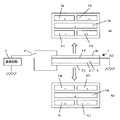
図1は本発明の超音波モータの振動体並びにその駆動法を示したものである。振動体1は圧電素子2a、2bと金属等の弾性体3から構成されている。図1(b)は側面から見た図、図1(a)は上面から見た図、図1(c)は下面から見た図である。第一の圧電素子2aは五つの領域に分けられ分極処理されている。幅方向に三分割され、更に両端の領域は長手方向に二分割された領域、即ち第一の圧電素子2aの一方の面に設けられた電極4a、4b、4c、4d、4eで示される領域に図中+、−の方向に厚み方向に分極処理されている。また、他方の面には、ほぼ全面に渡って電極4fが設けられている。電極4a、4b、4c、4dで示される領域は屈曲振動を、電極4eで示される領域は伸縮(縦)振動を励振する。第二の圧電素子2bも第一の圧電素子2bと同様に五つの領域に分けられ分極処理されている。但し図中+、−で示されるように屈曲振動を励振する領域の分極方向が第一の圧電素子2aとは反対になっている。また、他方の面には、ほぼ全面に渡って電極4lが設けられている。
【0015】
第一の圧電素子2a、第二の圧電素子2bの一方の面と他方の面の間に交流電圧を印加した際のモードパターンを夫々図2(a)、(b)に示す。左図が振動体1の長手方向に対する伸縮(縦)振動の振幅の変化の様子を、右図は屈曲振動の振幅の変化の様子を示したものである。図2から分かるように第一の圧電素子2aで励振される伸縮振動と屈曲振動の位相と第二の圧電素子2bで励振される伸縮振動と屈曲振動の位相とは逆になっている。
【0016】
従って、図1(b)に示すように弾性体3の両側に第一の圧電素子2aと第二の圧電素子2bを接着等の手段により接合し、電極4f、4lと接する弾性体3を接地する。そしてスイッチ6によって駆動回路5からの駆動信号を第一の圧電素子2aの電極4a、4b、4c、4d、4eに印加するか第二の圧電素子2bの電極4g、4h、4i、4j、4kに印加するかを選択する事により振動体1の端面に発生する振動変位による楕円運動の方向が逆転するため、振動体1と接する図示しない移動体は移動方向を変えられる。尚、振動体1の形状は伸縮振動の固有周波数と屈曲振動の固有周波数が一致するように決められている。そして駆動回路5からの駆動信号はこの固有周波数近傍の周波数の交流電圧である。
【0017】
この様に弾性体3に厚みの薄い圧電素子2a、2bを接着した構成としている為、低電圧で駆動出来ると共に、大きな機械的強度を保てる。
【0018】
(実施の形態2)
図3は本発明の超音波モータの振動体の第二の例を示したものである。
基本的な原理は実施の形態1と同じな為、相違点のみを述べる。本発明では弾性体3を用いずに第一の圧電素子2aと第二の圧電素子2bを一体的に積層し焼き固めた例である。ここでは駆動信号を印加しない側にある圧電素子の一方の面に有る電極と他方の面に有る電極をスイッチ7、8によって短絡する。このような構成にすることにより、駆動状態で発生した電荷による反電界により振動体9の振動が抑えられるのを防ぐことが可能となる。
尚、第一の圧電素子2a並びに第二の圧電素子2bは複数枚重ねて構成しても良い。
【0019】
この様に、駆動回路からの駆動信号が印加されていない電極を短絡する方法は本構成のモータに限ることではなく、他の原理・構成のモータに応用しても同様の効果が得られる。
【0020】
(実施の形態3)
図4、図5は本発明の超音波モータの圧電素子の別の例を示したものである。ここでも実施の形態1、2との相違点のみについて述べる。
【0021】
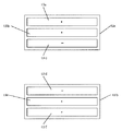
図4に示す圧電素子10a、10bは圧電素子2a、2bの変形例であり屈曲振動を励振する電極4a、4b、4c、4d並びに4g、4h、4i、4jに対応して電極11a、11b、11c、11d並びに11f、11g、11h、11iが設けられている。伸縮振動を励振する4e、4kに対応して電極11e、11jが設けられている。電極11e、11jは伸縮振動を強く励振するように振動の節部となる中央部分において幅方向全体に渡って電極を設けている。
【0022】
図5に示す圧電素子は実施の形態1に示したものと異なり、屈曲振動に一次の振動を励振する例を示したものである。圧電素子12a、12bの幅方向に三分割された領域、即ち圧電素子12a、12bの一方の面に設けられた電極13a、13b、13c並びに13d、13e、13fに示される領域に図中+、−の方向に分極処理されている。また他方の面には図示しないが全体に渡って電極が設けられている。
【0023】
このような構成とすることで第一の圧電素子12aで駆動した際には図6(a)の様に、第二の圧電素子12bで駆動した際には図6(b)の様に伸縮振動ならびに屈曲振動が励振される。図6から分かるように第一の圧電素子12aで励振される伸縮振動と屈曲振動の位相と第二の圧電素子2bで励振される伸縮振動と屈曲振動の位相とは逆になっている。従って、どちらの圧電素子を用いて駆動するかによって振動変位がなす楕円運動の方向が変わり、振動体と接する移動体の移動方向が変えられる。
【0024】
ここで電極13a、13b並びに13e、13fを繋ぎ合わせ、一つの電極で構成しても構わない。
【0025】
この様に、本発明においては圧電素子の電極や使用する振動モードの種類は問わない。そして、振動体の形状も矩形に限ることではなく円板状の形状等であっても構わない。
【0026】
(実施の形態4)
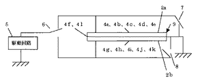
本発明の超音波モータを用いて電子機器を構成した例を図7を基に説明する。
【0027】
振動体1の中央部に設けられた弾性体3の長手方向中央部、即ち伸縮振動並びに屈曲振動の節部から幅方向に張り出し部3a、3bを有している。張り出し部3aを軸19の回転案内とすると共に、もう一方の張り出し部3bを加圧ばね14で加圧することにより弾性体3から張り出させた突起3cと移動体15が加圧接触する。移動体15の中心軸15a及び15bは案内板16、17によって回転可能に支持されている。第一の圧電素子2aの中央、即ち振動体に発生する伸縮振動と屈曲振動の節の位置には、電極4a、4b、4c、4d、4eを短絡する導通パターン20が設けられ、リード線21aが半田付けされている。導通パターンは半田でも良い。電極4fとの導通は張り出し部3aに接合したリード線21bによってとられている。また、図示しないが第二の圧電素子2bの導通も同様になされている。振動体1に駆動信号を印加し、伸縮振動と屈曲振動を励振すると、移動体15は回転し、中心軸15bに設けられた指針18も回転し、案内板17に印刷された文字盤の数字を示す。従って実施例1〜3記載の超音波モータ並びに本実施例に記載の導通構造を用いることで、小型薄型で効率の高い超音波モータが実現できるから、本実施例の様に時計を始めとする電子機器の駆動源に用いることで電子機器の小型薄型、軽量化並びに低消費電力化が図れる。
【0028】
ここでは移動体15を回転動作させたがレール等を駆動してリニヤ駆動しても構わない。また、移動体を固定して振動体自身を駆動しても構わない。
【0029】
【発明の効果】
本発明によれば小型、薄型、高出力で回転型/リニヤ型の両方にも適用可能な超音波モータが実現できる。特に単相信号で駆動でき、移動体の移動方向の切り替えは駆動信号を印加する圧電素子を選択するのみでよいから回路構成が簡単で小型な自励発振回路での駆動が可能となる。
【0030】
また、リード線等の導通手段の数も少なく構成できるため、小型化しても振動体の振動に影響を与えることは無く、高効率でばらつきの小さい超音波モータが実現できる。
【図面の簡単な説明】
【図1】本発明の実施の形態1にかかわる超音波モータの振動体の構成を示す図である。
【図2】本発明の実施の形態1にかかわる振動体の振動モードを示す図である。
【図3】本発明の実施の形態2にかかわる超音波モータの振動体の構成を示す図である。
【図4】本発明の実施の形態3にかかわる圧電素子の電極を示す図である。
【図5】本発明の実施の形態3にかかわる圧電素子の電極の別の例を示す図である。
【図6】本発明の実施の形態3にかかわる振動体の振動モードを示す図である。
【図7】本発明の超音波モータを用いた電子機器を示す図である。
【符号の説明】
圧電素子 2,10,12
弾性体 3
電極 4,11,13
振動体 1
移動体 15
加圧ばね 14[0001]
TECHNICAL FIELD OF THE INVENTION
The present invention relates to an ultrasonic motor that frictionally drives a moving body by vibration of a vibrating body, and more particularly to an ultrasonic motor that drives a moving body by exciting a stretching vibration and a bending vibration of a rectangular vibrating body.
[0002]
[Prior art]
Ultrasonic motors using the resonance mode of an elastic body have various features not found in electromagnetic motors, and are being developed for applications in precision equipment, information equipment, automobiles, industrial equipment, and the like. In recent years, a motor using the expansion and contraction vibration and the bending vibration of a rectangular vibrating body has been attracting attention because of its thin structure and both rotary / linear constructions (for example, see
[0003]
[Patent Document 1]
JP-A-2-41673 (page 2-3, FIG. 1-3)
[0004]
[Patent Document 2]
JP-A-7-184382 (pages 5-6, FIG. 1)
[0005]
[Problems to be solved by the invention]
However, what is disclosed in
[0006]
Further, the one disclosed in Patent Document 2 is provided with a polarization part for exciting stretching vibration and a polarization part for exciting bending vibration in one piezoelectric element. The moving direction of the moving body is changed by changing the phase of the drive signal applied to the polarization unit that excites the stretching vibration and the phase of the drive signal applied to the polarization unit that excites the bending vibration. However, in this method, it is difficult to drive the self-oscillation circuit because two different driving signals having different phases are required. In addition, since conducting means such as lead wires must be provided on a plurality of piezoelectric elements, when the device is miniaturized, it causes vibration loss, which not only reduces the characteristics and efficiency of the motor but also causes variations in the characteristics of each motor. .
[0007]
[Means for Solving the Problems]
Therefore, the ultrasonic motor of the present invention has a polarization unit for exciting the first vibration, a first piezoelectric element having a polarization unit for exciting the second vibration, and a polarization unit for exciting the first vibration. A vibrating body having a second piezoelectric element having a polarizing portion for exciting the second vibration, and a moving body in contact with the vibrating body, wherein the first piezoelectric element or the second piezoelectric element In an ultrasonic motor that drives the moving body by applying a drive signal to any of the elements, a phase relationship between the first vibration and the second vibration excited by the first piezoelectric element, An ultrasonic motor is characterized in that the phase relationship between the first vibration and the second vibration excited by the second piezoelectric element is shifted by 180 degrees. This makes it possible to use the entire surface of the piezoelectric element for driving and to excite a large bending vibration. The switching of the moving direction of the moving body may be performed simply by selecting the piezoelectric element to which the driving signal is applied, and the driving by the self-excited oscillation circuit becomes possible.
[0008]
In the ultrasonic motor according to the present invention, in particular, the vibrating body is formed of the first piezoelectric element, the second vibrating body, and the elastic body, or the vibrating body is formed of the first piezoelectric element and the second piezoelectric element. The element is formed by integrally laminating and firing. According to the former, the projections in contact with the support member and the moving body can be formed simultaneously by the elastic body. According to the latter, since no bonding is required, an ultrasonic motor having excellent reliability while eliminating loss of vibration in the bonding layer and individual products can be realized.
[0009]
In the ultrasonic motor of the present invention, the electrodes of the piezoelectric element to which no drive signal was applied were short-circuited. According to this, the electric charge generated in the piezoelectric element to which the drive signal is not applied during driving does not suppress the vibration, so that a large amplitude and a large output can be obtained.
[0010]
Further, a short-circuit means for short-circuiting all the electrodes provided corresponding to the respective polarized portions on the same surface of the piezoelectric element is provided. According to this, continuity can be obtained by one conduction means from the electrode surface divided into a plurality of parts, and particularly since conduction is obtained from the node portion, it does not affect the vibration of the vibrating body even if the size is reduced, An ultrasonic motor with high efficiency and small variation can be realized.
[0011]
In order to realize these configurations, the first vibration of the ultrasonic motor according to the present invention is a stretching vibration, and the second vibration is a bending vibration.
[0012]
By using the ultrasonic motor of the present invention as a drive source of an electronic device, it is possible to realize a small size, especially a thin product.
[0013]
BEST MODE FOR CARRYING OUT THE INVENTION
An embodiment of the present invention will be described with reference to the drawings, focusing on differences from the conventional example.
[0014]
(Embodiment 1)
FIG. 1 shows a vibrating body of an ultrasonic motor according to the present invention and a driving method thereof. The vibrating
[0015]
FIGS. 2A and 2B show mode patterns when an AC voltage is applied between one surface and the other surface of the first piezoelectric element 2a and the second
[0016]
Therefore, as shown in FIG. 1B, the first piezoelectric element 2a and the second
[0017]
Since the thin
[0018]
(Embodiment 2)
FIG. 3 shows a second example of the vibrator of the ultrasonic motor according to the present invention.
Since the basic principle is the same as in the first embodiment, only the differences will be described. The present invention is an example in which the first piezoelectric element 2a and the second
Note that the first piezoelectric element 2a and the second
[0019]
As described above, the method of short-circuiting the electrode to which the drive signal from the drive circuit is not applied is not limited to the motor having the present configuration, and the same effect can be obtained by applying to a motor having another principle and configuration.
[0020]
(Embodiment 3)
4 and 5 show another example of the piezoelectric element of the ultrasonic motor according to the present invention. Here, only the differences from the first and second embodiments will be described.
[0021]
The
[0022]
The piezoelectric element shown in FIG. 5 is different from that shown in the first embodiment and shows an example in which primary vibration is excited in bending vibration. In the area divided into three in the width direction of the
[0023]
With such a configuration, when driven by the first
[0024]
Here, the
[0025]
Thus, in the present invention, the type of the electrode of the piezoelectric element and the type of vibration mode to be used are not limited. The shape of the vibrating body is not limited to a rectangle, but may be a disk shape or the like.
[0026]
(Embodiment 4)
An example in which an electronic device is configured using the ultrasonic motor of the present invention will be described with reference to FIG.
[0027]
The
[0028]
Here, the moving
[0029]
【The invention's effect】
According to the present invention, it is possible to realize an ultrasonic motor that is small, thin, and has a high output and is applicable to both a rotary type and a linear type. In particular, it can be driven by a single-phase signal, and the moving direction of the moving body can be switched only by selecting the piezoelectric element to which the driving signal is applied.
[0030]
Further, since the number of conducting means such as lead wires can be reduced, the vibration of the vibrating body is not affected even if the size is reduced, and an ultrasonic motor with high efficiency and small variation can be realized.
[Brief description of the drawings]
FIG. 1 is a diagram showing a configuration of a vibrating body of an ultrasonic motor according to a first embodiment of the present invention.
FIG. 2 is a diagram showing a vibration mode of the vibrating body according to
FIG. 3 is a diagram showing a configuration of a vibrating body of an ultrasonic motor according to a second embodiment of the present invention.
FIG. 4 is a diagram showing electrodes of a piezoelectric element according to a third embodiment of the present invention.
FIG. 5 is a diagram showing another example of the electrodes of the piezoelectric element according to the third embodiment of the present invention.
FIG. 6 is a diagram showing a vibration mode of a vibrating body according to
FIG. 7 is a diagram showing an electronic device using the ultrasonic motor of the present invention.
[Explanation of symbols]
Piezoelectric elements 2, 10, 12
Moving
Pressure spring 14
Claims (7)
前記第一の圧電素子により励振される前記第一の振動と前記第二の振動の位相関係と、前記第二の圧電素子により励振される前記第一の振動と前記第二の振動の位相関係とは180度ずれていることを特徴とする超音波モータ。A first piezoelectric element having a polarization unit that excites the first vibration and a polarization unit that excites the second vibration, a polarization unit that excites the first vibration, and excites the second vibration A vibrating body having a second piezoelectric element having a polarizing portion, and a moving body that comes into contact with the vibrating body, and applying a drive signal to either the first piezoelectric element or the second piezoelectric element. In the ultrasonic motor that drives the moving body by doing
The phase relationship between the first vibration and the second vibration excited by the first piezoelectric element, and the phase relationship between the first vibration and the second vibration excited by the second piezoelectric element An ultrasonic motor characterized by being shifted 180 degrees from the ultrasonic motor.
Priority Applications (1)
| Application Number | Priority Date | Filing Date | Title |
|---|---|---|---|
| JP2002364974A JP4388273B2 (en) | 2002-12-17 | 2002-12-17 | Ultrasonic motor and electronic device with ultrasonic motor |
Applications Claiming Priority (1)
| Application Number | Priority Date | Filing Date | Title |
|---|---|---|---|
| JP2002364974A JP4388273B2 (en) | 2002-12-17 | 2002-12-17 | Ultrasonic motor and electronic device with ultrasonic motor |
Related Child Applications (1)
| Application Number | Title | Priority Date | Filing Date |
|---|---|---|---|
| JP2009199958A Division JP4918122B2 (en) | 2009-08-31 | 2009-08-31 | Ultrasonic motor and electronic device with ultrasonic motor |
Publications (2)
| Publication Number | Publication Date |
|---|---|
| JP2004201380A true JP2004201380A (en) | 2004-07-15 |
| JP4388273B2 JP4388273B2 (en) | 2009-12-24 |
Family
ID=32762649
Family Applications (1)
| Application Number | Title | Priority Date | Filing Date |
|---|---|---|---|
| JP2002364974A Expired - Fee Related JP4388273B2 (en) | 2002-12-17 | 2002-12-17 | Ultrasonic motor and electronic device with ultrasonic motor |
Country Status (1)
| Country | Link |
|---|---|
| JP (1) | JP4388273B2 (en) |
Cited By (1)
| Publication number | Priority date | Publication date | Assignee | Title |
|---|---|---|---|---|
| EP1928036A2 (en) | 2006-11-29 | 2008-06-04 | Olympus Corporation | Ultrasonic motor and microscope stage |
-
2002
- 2002-12-17 JP JP2002364974A patent/JP4388273B2/en not_active Expired - Fee Related
Cited By (2)
| Publication number | Priority date | Publication date | Assignee | Title |
|---|---|---|---|---|
| EP1928036A2 (en) | 2006-11-29 | 2008-06-04 | Olympus Corporation | Ultrasonic motor and microscope stage |
| US7635940B2 (en) | 2006-11-29 | 2009-12-22 | Olympus Corporation | Ultrasonic motor and microscope stage |
Also Published As
| Publication number | Publication date |
|---|---|
| JP4388273B2 (en) | 2009-12-24 |
Similar Documents
| Publication | Publication Date | Title |
|---|---|---|
| JP4510179B2 (en) | Ultrasonic motor and electronic equipment with ultrasonic motor | |
| US4678956A (en) | Vibration wave motor | |
| JP2004282841A (en) | Ultrasonic oscillator and ultrasonic motor | |
| JP4918122B2 (en) | Ultrasonic motor and electronic device with ultrasonic motor | |
| JP4564582B2 (en) | Ultrasonic actuator | |
| JPH0458273B2 (en) | ||
| JPH0421371A (en) | Oscillation wave motor | |
| JP4563490B2 (en) | Ultrasonic motor and electronic device with ultrasonic motor | |
| JPH05146171A (en) | Ultrasonic oscillator | |
| JP4388273B2 (en) | Ultrasonic motor and electronic device with ultrasonic motor | |
| JP4641709B2 (en) | Ultrasonic motor using laminated piezoelectric vibrator and electronic device using the same | |
| JP2004304963A (en) | Piezoelectric actuator | |
| JP4673420B2 (en) | Multilayer piezoelectric vibrator, ultrasonic motor, and electronic device with ultrasonic motor | |
| JP2008278710A (en) | Piezoelectric element and vibration actuator | |
| JP3432056B2 (en) | Laminated piezoelectric element, method of manufacturing laminated piezoelectric element, vibration device using laminated piezoelectric element, and driving device using the same | |
| JPH03265477A (en) | Ultrasonic wave oscillator, oscillating method, driver and driving method employing the same | |
| JP5216822B2 (en) | Ultrasonic motor using laminated piezoelectric vibrator and electronic device using the same | |
| JP2010004625A (en) | Piezoelectric vibrator and method of driving the same | |
| JP2010246347A (en) | Ultrasonic motor | |
| JPH0284076A (en) | Vibrator type actuator | |
| JPH0628951Y2 (en) | Piezoelectric actuator | |
| JP2002017094A (en) | Ultrasonic motor drive | |
| JPH07274549A (en) | Ultrasonic motor and driving apparatus therefor | |
| JPH06121557A (en) | Ultrasonic motor and driving method therefor | |
| US8421309B2 (en) | Ultrasonic motor |
Legal Events
| Date | Code | Title | Description |
|---|---|---|---|
| A621 | Written request for application examination |
Free format text: JAPANESE INTERMEDIATE CODE: A621 Effective date: 20051109 |
|
| A131 | Notification of reasons for refusal |
Free format text: JAPANESE INTERMEDIATE CODE: A131 Effective date: 20080924 |
|
| A521 | Written amendment |
Free format text: JAPANESE INTERMEDIATE CODE: A523 Effective date: 20081121 |
|
| A131 | Notification of reasons for refusal |
Free format text: JAPANESE INTERMEDIATE CODE: A131 Effective date: 20090707 |
|
| A521 | Written amendment |
Free format text: JAPANESE INTERMEDIATE CODE: A523 Effective date: 20090831 |
|
| TRDD | Decision of grant or rejection written | ||
| A01 | Written decision to grant a patent or to grant a registration (utility model) |
Free format text: JAPANESE INTERMEDIATE CODE: A01 Effective date: 20090929 |
|
| A01 | Written decision to grant a patent or to grant a registration (utility model) |
Free format text: JAPANESE INTERMEDIATE CODE: A01 |
|
| A61 | First payment of annual fees (during grant procedure) |
Free format text: JAPANESE INTERMEDIATE CODE: A61 Effective date: 20091002 |
|
| R150 | Certificate of patent or registration of utility model |
Free format text: JAPANESE INTERMEDIATE CODE: R150 |
|
| FPAY | Renewal fee payment (event date is renewal date of database) |
Free format text: PAYMENT UNTIL: 20121009 Year of fee payment: 3 |
|
| RD01 | Notification of change of attorney |
Free format text: JAPANESE INTERMEDIATE CODE: A7421 Effective date: 20091113 |
|
| FPAY | Renewal fee payment (event date is renewal date of database) |
Free format text: PAYMENT UNTIL: 20121009 Year of fee payment: 3 |
|
| FPAY | Renewal fee payment (event date is renewal date of database) |
Free format text: PAYMENT UNTIL: 20131009 Year of fee payment: 4 |
|
| LAPS | Cancellation because of no payment of annual fees |