JP2004201248A - Surveillance camera system - Google Patents
Surveillance camera system Download PDFInfo
- Publication number
- JP2004201248A JP2004201248A JP2002370695A JP2002370695A JP2004201248A JP 2004201248 A JP2004201248 A JP 2004201248A JP 2002370695 A JP2002370695 A JP 2002370695A JP 2002370695 A JP2002370695 A JP 2002370695A JP 2004201248 A JP2004201248 A JP 2004201248A
- Authority
- JP
- Japan
- Prior art keywords
- cmd
- surveillance camera
- communication network
- server
- transmitted
- Prior art date
- Legal status (The legal status is an assumption and is not a legal conclusion. Google has not performed a legal analysis and makes no representation as to the accuracy of the status listed.)
- Granted
Links
Images


Landscapes
- Studio Devices (AREA)
- Selective Calling Equipment (AREA)
- Closed-Circuit Television Systems (AREA)
Abstract
Description
【0001】
【発明の属する技術分野】
本発明は、監視カメラと、監視カメラの動作を制御する制御手段と、通信ネットワークを介して制御手段に監視カメラの動作制御命令を送信するとともに、監視カメラで撮影した画像を受信する情報送受信手段とから構成される監視カメラシステムに関する。
【0002】
【従来の技術】
現在、監視カメラは、金融機関、コンビニエンスストアなどに設置される防犯を目的としたものだけでなく、老人介護や工場の自動生産管理などにも広く利用されている。従来、このような監視カメラで撮影した画像を、パソコンや携帯型情報端末などのディスプレイ画面上に表示し、この表示画面を観察しながら監視カメラの撮影位置(パン、チルト、ズームなど)を遠隔操作するシステムが知られている。
【0003】
上記のようなシステムには、遠隔操作の指示命令に迅速に対処するために、複数の遠隔操作装置からの監視カメラの制御権獲得要求を管理するサーバを備えたものが提案されている(特許文献1参照)。このサーバは、それぞれの遠隔操作装置から発行された獲得要求を、現在制御権を有する遠隔操作装置が制御権を放棄するまでキューイングし、キューイングされた情報に応じて監視カメラの制御権を遠隔操作装置に付与する。
【0004】
【特許文献1】
特開平10−93855号公報
【0005】
【発明が解決しようとする課題】
特許文献1に記載されるシステムでは、監視カメラの動作を制御する制御装置、または制御装置に接続されたサーバは、遠隔操作装置からの制御命令を受信するために、ネットワークに常時接続され、常にネットワークからの接続要求に対応可能にしておく必要がある。このため、ネットワークの構築作業が複雑にならざるを得ず、且つシステムの安全性に問題があった。
【0006】
本発明は、ネットワークの構築が容易で、システムの安全性を向上させることができる監視カメラシステムを提供することを目的とする。
【0007】
【課題を解決するための手段】
上記目的を達成するために、本発明は、監視対象を撮影する監視カメラと、監視カメラの動作を制御する制御手段と、通信ネットワークを介して制御手段に監視カメラの動作制御命令を送信するとともに、監視カメラで撮影した画像を受信する情報送受信手段とから構成される監視カメラシステムにおいて、前記通信ネットワークに接続され、前記監視カメラで撮影した画像および前記動作制御命令を保存するサーバを備えたことを特徴とする。
【0008】
なお、前記制御手段は、間欠的に前記通信ネットワークに接続することが好ましい。また、前記サーバは、前記制御手段に前回送信された動作制御命令と、今回送信する動作制御命令との重複部分を相殺・整理して送信することが好ましい。
【0009】
【発明の実施の形態】
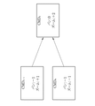
図1において、監視カメラシステム2は、監視カメラ10と、パーソナルコンピュータ(PC)11と、第1、第2携帯型情報端末(PA 、PB )12、13とから構成される。この監視カメラシステム2は、システムの管理者が所有するPA 12、PB 13から送信され、監視カメラ10の撮影方向および撮影範囲を指定する動作制御命令(CMD)に応じて、監視カメラ10を遠隔操作するものである。
【0010】
監視カメラ10は、PC11により動作制御され、所定の撮影間隔で監視対象の静止画像を撮影する。この監視カメラ10は、上下左右に首振り自在な首振り機能とズーム機能とを有しており、撮影方向および撮影範囲の変更が可能となっている。監視カメラ10で撮影された画像は、PC11のモニタ11aに表示され、図示しないメモリに保存される。なお、監視カメラ10とPC11との接続方法は、ケーブルなどを用いた有線接続であってもよいし、無線接続であってもよい。
【0011】
PC11は、電話回線14を介して通信ネットワーク15に間欠的に接続されており、一定の間隔で通信ネットワーク15との接続・切断を繰り返し行っている。このPC11は、メモリに保存された監視カメラ10で撮影した画像を、通信ネットワーク15を介してPA 12、PB 13に送信するとともに、PA 12、PB 13から後述するサーバ16を介してCMDを受信し、受信したCMDに基づいて監視カメラ10の動作を制御する。
【0012】
PA 12、PB 13には、アンテナ12a、13aと、モニタ12b、13bと、操作部12c、13cとが設けられている。PA 12、PB 13は、アンテナ12a、13aにより通信ネットワーク15との無線通信が可能となっており、監視カメラ10の動作とは関係なく、非同期で通信ネットワーク15に接続することができる。モニタ12b、13bには、監視カメラ10で撮影した画像が表示される。操作部12c、13cは、CMDを入力する際に操作される。
【0013】
通信ネットワーク15には、サーバ16が接続されている。サーバ16は、PC11から送信される監視カメラ10で撮影した画像と、PA 12、PB 13から送信されるCMDを保存する。
【0014】
図2に、サーバ16の動作フローチャートを示す。初期状態では、サーバ16はPC11、およびPA 12、PB 13からのアクセス待ち状態となっている。PC11からアクセスがあり、且つCMDがサーバ16に保存されている場合は、PC11にCMDを送信する。このとき、サーバ16は、PC11に前回送信されたCMDn-1 と、今回送信するCMDn との重複部分を相殺・整理して送信する。すなわち、図3に示すように、CMDn-1 が左方向にパン1段階(−1、基準の撮影位置および撮影範囲を0とする。)、ワイド側にズーム1段階(+1)、CMDn が左方向にパン1段階(−1)、テレ側にズーム1段階(−1)変更する命令であった場合、パンの変更を相殺して、ワイド側にズーム2段階(+2)変更する命令をPC11に送信する。このようにすると、CMDのデータ量やCMDを実行する際の動作ステップを減らすことができる。
【0015】
図2において、サーバ16は、送信済みのCMDを消去した後、PC11から送信された画像を保存する。CMDが保存されていない場合は、直ちにPC11からの画像送信待ち状態となり、PC11から送信された画像を保存する。画像保存後は処理をリターンして再びアクセス待ち状態となる。
【0016】
PA 12、PB 13からアクセスがあり、送信された信号が監視カメラ10で撮影した画像の取得要求であった場合は、保存した画像をPA 12、PB 13に送信する。送信された信号がCMDであった場合は、このCMDを保存する。画像送信後、またはCMDの保存後は、処理をリターンして再びアクセス待ち状態となる。
【0017】
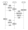
次に、監視カメラシステム2の動作手順について、図4〜図6のフローチャートを参照して説明する。図4および図5に示すように、PC11は、所定の撮影間隔で監視対象の撮影を監視カメラ10に指示する。また、PC11は、電話回線14を介して一定の間隔で通信ネットワーク15に接続し、監視カメラ10で撮影した画像をサーバ16に送信した後、通信ネットワーク15との接続を切断する。
【0018】
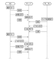
サーバ16は、PC11から送信された画像を保存し、PA 12、PB 13から監視カメラ10で撮影した画像の取得要求を受信した場合は、直近に保存した画像をPA 12、PB 13に送信する。一方、図5に示すように、PA 12、PB 13からCMDを受信した場合は、このCMDを保存し、次にPC11からのアクセスがあったときに、保存したCMDをPC11に送信して消去する。
【0019】
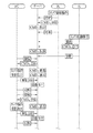
図6に示すように、PA 12、PB 13の双方からCMDが送信された場合は、サーバ16はPA 12、PB 13から送信されるCMDA 、CMDB をそれぞれ保存する。CMDA 、CMDB の保存後、PC11からの最初のアクセスでPC11にCMDA を送信する。PC11は、CMDA に基づいて監視カメラ10の撮影位置および撮影範囲を変更し、監視カメラ10に撮影を指示する。監視カメラ10は、PC11で制御された撮影位置および撮影範囲で監視対象の撮影を行い、撮影した画像をPC11に送信する。
【0020】
CMDA の送信後、サーバ16は、CMDB とCMDA との重複部分を相殺・整理し、CMDA を消去する。そして、PC11からの次のアクセスで、PC11にCMDB を送信し、消去する。PC11は、CMDA が送信された場合と同様に、CMDB に基づいて監視カメラ10の撮影位置および撮影範囲を変更し、監視カメラ10に撮影を指示する。監視カメラ10は、PC11で制御された撮影位置および撮影範囲で監視対象の撮影を行い、撮影した画像をPC11に送信する。このような構成であると、通信ネットワーク15を介してPC11がPA 12、PB 13と常時接続されていなくても、画像やCMDの送受信を確実に行うことができる。
【0021】
上記実施形態では、1台の監視カメラ、2台の携帯型情報端末からシステムを構成しているが、本発明はこれに限らず、複数台の監視カメラ、2台以上の携帯型情報端末からなるシステムにも適用することができる。また、携帯型情報端末から送信する動作制御命令としては、ストロボ発光の有無や撮影画像の記録サイズなど適宜付加することが可能である。さらに、サーバから携帯型情報端末への画像送信は、定期的に自動で行ってもよい。
【0022】
【発明の効果】
以上のように、本発明の監視カメラシステムによれば、通信ネットワークに接続され、監視カメラで撮影した画像および動作制御命令を保存するサーバを備えたので、ネットワークの構築が容易で、システムの安全性を向上させることができる。
【0023】
また、サーバは、制御手段に前回送信された動作制御命令と、今回送信する動作制御命令との重複部分を相殺・整理して送信するので、動作制御命令のデータ量や動作制御命令を実行する際の動作ステップを減らすことができる。
【図面の簡単な説明】
【図1】本発明の監視カメラシステムを示す概略図である。
【図2】サーバの動作手順を示すフローチャートである。
【図3】動作制御命令を相殺・整理する際の一例を示す図である。
【図4】監視カメラシステムの動作を示すフローチャートである。
【図5】監視カメラシステムの動作を示すフローチャートである。
【図6】監視カメラシステムの動作を示すフローチャートである。
【符号の説明】
2 監視カメラシステム
10 監視カメラ
11 パーソナルコンピュータ(PC)
12 第1携帯型情報端末(PA )
13 第2携帯型情報端末(PB )
15 通信ネットワーク
16 サーバ[0001]
BACKGROUND OF THE INVENTION
The present invention relates to a surveillance camera, a control means for controlling the operation of the surveillance camera, and an information transmission / reception means for transmitting an operation control command of the surveillance camera to the control means via a communication network and receiving an image taken by the surveillance camera. The surveillance camera system comprised from these.
[0002]
[Prior art]
Currently, surveillance cameras are widely used not only for crime prevention purposes installed at financial institutions and convenience stores, but also for elderly care and automatic production management at factories. Conventionally, images taken with such a surveillance camera are displayed on the display screen of a personal computer or portable information terminal, etc., and the shooting position (pan, tilt, zoom, etc.) of the surveillance camera is remotely monitored while observing this display screen. Systems to operate are known.
[0003]
In order to quickly cope with a remote operation instruction command, a system including a server that manages a request for acquiring a control right of a monitoring camera from a plurality of remote operation devices has been proposed (patent) Reference 1). This server queues the acquisition request issued from each remote control device until the remote control device having the current control right gives up the control right, and assigns the control right of the surveillance camera according to the queued information. It is given to the remote control device.
[0004]
[Patent Document 1]
Japanese Patent Application Laid-Open No. 10-93855
[Problems to be solved by the invention]
In the system described in
[0006]
It is an object of the present invention to provide a surveillance camera system that can easily construct a network and can improve the safety of the system.
[0007]
[Means for Solving the Problems]
In order to achieve the above object, the present invention transmits a monitoring camera operation control command to a control unit via a communication network, a control unit that controls the operation of the monitoring camera, and a control unit that controls the operation of the monitoring camera. And a monitoring camera system comprising information transmitting / receiving means for receiving an image taken by the surveillance camera, comprising a server connected to the communication network and storing the image taken by the surveillance camera and the operation control command. It is characterized by.
[0008]
The control means is preferably intermittently connected to the communication network. Moreover, it is preferable that the server cancels and arranges an overlapping portion between the operation control command transmitted to the control unit last time and the operation control command transmitted this time, and transmits the same.
[0009]
DETAILED DESCRIPTION OF THE INVENTION
In FIG. 1, the monitoring camera system 2 includes a monitoring camera 10, a personal computer (PC) 11, and first and second portable information terminals (P A and P B ) 12 and 13. The surveillance camera system 2 is transmitted from the
[0010]
The surveillance camera 10 is controlled in operation by the PC 11 and shoots a still image to be monitored at a predetermined shooting interval. This surveillance camera 10 has a swing function and a zoom function that can be swung up and down and left and right, and can change a shooting direction and a shooting range. An image taken by the monitoring camera 10 is displayed on the
[0011]
The PC 11 is intermittently connected to the
[0012]
The
[0013]
A
[0014]
FIG. 2 shows an operation flowchart of the
[0015]
In FIG. 2, the
[0016]
When there is an access from
[0017]
Next, the operation procedure of the surveillance camera system 2 will be described with reference to the flowcharts of FIGS. As shown in FIGS. 4 and 5, the
[0018]
When the
[0019]
As shown in FIG. 6, when CMD is transmitted from both
[0020]
After the transmission of CMD A , the
[0021]
In the above embodiment, the system is composed of one surveillance camera and two portable information terminals. However, the present invention is not limited to this, and a plurality of surveillance cameras and two or more portable information terminals are used. It can be applied to the system. Further, as the operation control command transmitted from the portable information terminal, it is possible to appropriately add the presence / absence of strobe light emission, the recording size of the photographed image, and the like. Furthermore, the image transmission from the server to the portable information terminal may be automatically performed periodically.
[0022]
【The invention's effect】
As described above, according to the surveillance camera system of the present invention, the server is connected to the communication network and stores the images taken by the surveillance camera and the operation control commands, so that the network can be easily constructed and the system is safe. Can be improved.
[0023]
In addition, since the server cancels and arranges the overlapping part of the operation control command transmitted to the control means last time and the operation control command transmitted this time, the data amount of the operation control command and the operation control command are executed. The operation step can be reduced.
[Brief description of the drawings]
FIG. 1 is a schematic diagram showing a surveillance camera system of the present invention.
FIG. 2 is a flowchart showing an operation procedure of the server.
FIG. 3 is a diagram illustrating an example when canceling and organizing operation control commands.
FIG. 4 is a flowchart showing the operation of the surveillance camera system.
FIG. 5 is a flowchart showing the operation of the surveillance camera system.
FIG. 6 is a flowchart showing the operation of the surveillance camera system.
[Explanation of symbols]
2 Surveillance camera system 10
12 first portable information terminal (P A)
13 Second portable information terminal (P B )
15
Claims (3)
前記通信ネットワークに接続され、前記監視カメラで撮影した画像および前記動作制御命令を保存するサーバを備えたことを特徴とする監視カメラシステム。Information transmission / reception for transmitting monitoring camera operation control commands to the control means via the communication network and receiving images taken by the monitoring camera, and a monitoring camera for capturing the monitoring target, a control means for controlling the operation of the monitoring camera A surveillance camera system comprising:
A surveillance camera system comprising a server connected to the communication network and storing an image taken by the surveillance camera and the operation control command.
Priority Applications (1)
| Application Number | Priority Date | Filing Date | Title |
|---|---|---|---|
| JP2002370695A JP3992189B2 (en) | 2002-12-20 | 2002-12-20 | Surveillance camera system |
Applications Claiming Priority (1)
| Application Number | Priority Date | Filing Date | Title |
|---|---|---|---|
| JP2002370695A JP3992189B2 (en) | 2002-12-20 | 2002-12-20 | Surveillance camera system |
Publications (2)
| Publication Number | Publication Date |
|---|---|
| JP2004201248A true JP2004201248A (en) | 2004-07-15 |
| JP3992189B2 JP3992189B2 (en) | 2007-10-17 |
Family
ID=32766544
Family Applications (1)
| Application Number | Title | Priority Date | Filing Date |
|---|---|---|---|
| JP2002370695A Expired - Fee Related JP3992189B2 (en) | 2002-12-20 | 2002-12-20 | Surveillance camera system |
Country Status (1)
| Country | Link |
|---|---|
| JP (1) | JP3992189B2 (en) |
-
2002
- 2002-12-20 JP JP2002370695A patent/JP3992189B2/en not_active Expired - Fee Related
Also Published As
| Publication number | Publication date |
|---|---|
| JP3992189B2 (en) | 2007-10-17 |
Similar Documents
| Publication | Publication Date | Title |
|---|---|---|
| US7231654B2 (en) | Remote monitoring method and monitor control server | |
| US7218993B2 (en) | Robot system and autonomous mobile robot | |
| US8064080B2 (en) | Control of data distribution apparatus and data distribution system | |
| CN104468578A (en) | Priority communication system and communication method of wireless communication device | |
| WO2005002228A1 (en) | Portable surveillance camera and personal surveillance system using the same | |
| JP2012216102A (en) | Image storage system | |
| US20180213185A1 (en) | Method and system for monitoring a scene based on a panoramic view | |
| JP7344703B2 (en) | Control device and its control method and program | |
| JP5154341B2 (en) | Image monitoring apparatus and program | |
| JP2012119971A (en) | Monitoring video display unit | |
| JP6941458B2 (en) | Monitoring system | |
| JP3992189B2 (en) | Surveillance camera system | |
| JP4533708B2 (en) | Surveillance camera system, control device for surveillance camera system, and control method | |
| KR100323651B1 (en) | Monitoring System using a network | |
| KR20180028282A (en) | Image duplexing repeater system using ip camera | |
| KR101902276B1 (en) | Portable Security Surveillance System and Method by Using Camera | |
| KR20190114223A (en) | Surveillance system and operation method thereof | |
| JP2005318445A (en) | Home device of remote monitor system | |
| KR20070105062A (en) | Remote monitoring system and method using an image capturing terminal | |
| JP2003023619A (en) | Image server and image server system | |
| JP2001006094A (en) | Surveillance camera device and surveillance system using the same | |
| JP7212257B2 (en) | Surveillance system, image licensing method, and image usage licensing program | |
| JP2001157105A (en) | Remote photographing system | |
| KR101087075B1 (en) | How to send / receive command using video line | |
| KR200279418Y1 (en) | Wireless remote security system |
Legal Events
| Date | Code | Title | Description |
|---|---|---|---|
| A621 | Written request for application examination |
Free format text: JAPANESE INTERMEDIATE CODE: A621 Effective date: 20050217 |
|
| A711 | Notification of change in applicant |
Free format text: JAPANESE INTERMEDIATE CODE: A712 Effective date: 20061218 |
|
| A977 | Report on retrieval |
Free format text: JAPANESE INTERMEDIATE CODE: A971007 Effective date: 20070709 |
|
| TRDD | Decision of grant or rejection written | ||
| A01 | Written decision to grant a patent or to grant a registration (utility model) |
Free format text: JAPANESE INTERMEDIATE CODE: A01 Effective date: 20070718 |
|
| A61 | First payment of annual fees (during grant procedure) |
Free format text: JAPANESE INTERMEDIATE CODE: A61 Effective date: 20070719 |
|
| R150 | Certificate of patent or registration of utility model |
Ref document number: 3992189 Country of ref document: JP Free format text: JAPANESE INTERMEDIATE CODE: R150 Free format text: JAPANESE INTERMEDIATE CODE: R150 |
|
| FPAY | Renewal fee payment (event date is renewal date of database) |
Free format text: PAYMENT UNTIL: 20100803 Year of fee payment: 3 |
|
| FPAY | Renewal fee payment (event date is renewal date of database) |
Free format text: PAYMENT UNTIL: 20110803 Year of fee payment: 4 |
|
| R250 | Receipt of annual fees |
Free format text: JAPANESE INTERMEDIATE CODE: R250 |
|
| FPAY | Renewal fee payment (event date is renewal date of database) |
Free format text: PAYMENT UNTIL: 20110803 Year of fee payment: 4 |
|
| FPAY | Renewal fee payment (event date is renewal date of database) |
Free format text: PAYMENT UNTIL: 20120803 Year of fee payment: 5 |
|
| R250 | Receipt of annual fees |
Free format text: JAPANESE INTERMEDIATE CODE: R250 |
|
| FPAY | Renewal fee payment (event date is renewal date of database) |
Free format text: PAYMENT UNTIL: 20120803 Year of fee payment: 5 |
|
| FPAY | Renewal fee payment (event date is renewal date of database) |
Free format text: PAYMENT UNTIL: 20130803 Year of fee payment: 6 |
|
| R250 | Receipt of annual fees |
Free format text: JAPANESE INTERMEDIATE CODE: R250 |
|
| R250 | Receipt of annual fees |
Free format text: JAPANESE INTERMEDIATE CODE: R250 |
|
| R250 | Receipt of annual fees |
Free format text: JAPANESE INTERMEDIATE CODE: R250 |
|
| R250 | Receipt of annual fees |
Free format text: JAPANESE INTERMEDIATE CODE: R250 |
|
| R250 | Receipt of annual fees |
Free format text: JAPANESE INTERMEDIATE CODE: R250 |
|
| R250 | Receipt of annual fees |
Free format text: JAPANESE INTERMEDIATE CODE: R250 |
|
| R250 | Receipt of annual fees |
Free format text: JAPANESE INTERMEDIATE CODE: R250 |
|
| R250 | Receipt of annual fees |
Free format text: JAPANESE INTERMEDIATE CODE: R250 |
|
| R250 | Receipt of annual fees |
Free format text: JAPANESE INTERMEDIATE CODE: R250 |
|
| R250 | Receipt of annual fees |
Free format text: JAPANESE INTERMEDIATE CODE: R250 |
|
| LAPS | Cancellation because of no payment of annual fees |