JP2004200641A - Nand type magnetic resistance ram - Google Patents
Nand type magnetic resistance ram Download PDFInfo
- Publication number
- JP2004200641A JP2004200641A JP2003187061A JP2003187061A JP2004200641A JP 2004200641 A JP2004200641 A JP 2004200641A JP 2003187061 A JP2003187061 A JP 2003187061A JP 2003187061 A JP2003187061 A JP 2003187061A JP 2004200641 A JP2004200641 A JP 2004200641A
- Authority
- JP
- Japan
- Prior art keywords
- nand type
- read
- transistors
- mtj cells
- magnetoresistive ram
- Prior art date
- Legal status (The legal status is an assumption and is not a legal conclusion. Google has not performed a legal analysis and makes no representation as to the accuracy of the status listed.)
- Granted
Links
Images


Classifications
-
- B—PERFORMING OPERATIONS; TRANSPORTING
- B82—NANOTECHNOLOGY
- B82Y—SPECIFIC USES OR APPLICATIONS OF NANOSTRUCTURES; MEASUREMENT OR ANALYSIS OF NANOSTRUCTURES; MANUFACTURE OR TREATMENT OF NANOSTRUCTURES
- B82Y10/00—Nanotechnology for information processing, storage or transmission, e.g. quantum computing or single electron logic
-
- G—PHYSICS
- G11—INFORMATION STORAGE
- G11C—STATIC STORES
- G11C11/00—Digital stores characterised by the use of particular electric or magnetic storage elements; Storage elements therefor
- G11C11/02—Digital stores characterised by the use of particular electric or magnetic storage elements; Storage elements therefor using magnetic elements
- G11C11/14—Digital stores characterised by the use of particular electric or magnetic storage elements; Storage elements therefor using magnetic elements using thin-film elements
- G11C11/15—Digital stores characterised by the use of particular electric or magnetic storage elements; Storage elements therefor using magnetic elements using thin-film elements using multiple magnetic layers
-
- G—PHYSICS
- G11—INFORMATION STORAGE
- G11C—STATIC STORES
- G11C11/00—Digital stores characterised by the use of particular electric or magnetic storage elements; Storage elements therefor
- G11C11/02—Digital stores characterised by the use of particular electric or magnetic storage elements; Storage elements therefor using magnetic elements
- G11C11/16—Digital stores characterised by the use of particular electric or magnetic storage elements; Storage elements therefor using magnetic elements using elements in which the storage effect is based on magnetic spin effect
-
- H—ELECTRICITY
- H10—SEMICONDUCTOR DEVICES; ELECTRIC SOLID-STATE DEVICES NOT OTHERWISE PROVIDED FOR
- H10B—ELECTRONIC MEMORY DEVICES
- H10B61/00—Magnetic memory devices, e.g. magnetoresistive RAM [MRAM] devices
- H10B61/20—Magnetic memory devices, e.g. magnetoresistive RAM [MRAM] devices comprising components having three or more electrodes, e.g. transistors
- H10B61/22—Magnetic memory devices, e.g. magnetoresistive RAM [MRAM] devices comprising components having three or more electrodes, e.g. transistors of the field-effect transistor [FET] type
Landscapes
- Engineering & Computer Science (AREA)
- Chemical & Material Sciences (AREA)
- Nanotechnology (AREA)
- Computer Hardware Design (AREA)
- Physics & Mathematics (AREA)
- Mathematical Physics (AREA)
- Theoretical Computer Science (AREA)
- Crystallography & Structural Chemistry (AREA)
- Mram Or Spin Memory Techniques (AREA)
- Hall/Mr Elements (AREA)
- Semiconductor Memories (AREA)
Abstract
Description
【0001】
【発明の属する技術分野】
本発明はNAND型磁気抵抗ラムに関し、磁気抵抗ラムのセル構造を改善してセル当りの有効面積を減少させ、集積度を向上させることができるようにするNAND型磁気抵抗ラムに関する。
【0002】
【従来の技術】
現在、殆どの半導体メモリ製造会社等は、次世代記憶素子の1つとして強磁性体物質を利用した磁気抵抗ラムの開発に積極的に参加している。
【0003】
磁気抵抗ラムは、強磁性薄膜を多層に形成して各薄膜層の磁化方向に伴う電流変化を感知することによりデータを読出し及び書込みすることができる記憶素子である。このような磁気抵抗ラムは、磁性薄膜固有の特性により高速、低電力及び高集積化が可能であるだけでなく、フラッシュメモリのように非揮発性メモリ動作が可能な素子である。
【0004】
これに対する研究は現在初期段階にあり、主に多層磁性薄膜の形成に集中されている。そして、単位セルの構造及び周辺感知回路等に対する研究は未だ不完全な実情である。
【0005】
図4は、このような従来の磁気抵抗ラムの多層磁性薄膜構造であり、MTJ(Magnetic Tunnel Junction、磁気トンネル接合)セルの断面図である。
一般に、MTJセル5は半磁性体(anti-ferroelectric)薄膜1、固定層強磁性体薄膜2、トンネリング電流が流れる薄い絶縁層3、及び自由層強磁性体薄膜4で形成される。
【0006】
ここで、固定層強磁性体薄膜2は磁化方向が一方向に固定されている。そして、半磁性体薄膜1は固定層強磁性体薄膜2の磁化方向が変化しないよう固定する役割を果たす。一方、自由層強磁性体薄膜4は外部磁場により磁化方向が変化することになる。そして、自由層強磁性体薄膜4の磁化方向に従い「0」又は「1」のデータを記憶することができる。
【0007】
このようなMTJセル5の垂直方向に電流が流れる場合、薄い絶縁層3を通じてトンネリング電流が発生することになる。このとき、固定層強磁性体薄膜2と自由層強磁性体薄膜4の磁化方向が同一であれば、トンネリング電流の大きさが大きい。逆に、固定層強磁性体薄膜2と自由層強磁性体薄膜4の磁化方向が逆の場合は、小さいトンネリング電流が流れることになる。
【0008】
このような現象をTMR(Tunneling Magnetoresistance、トンネル磁気抵抗)効果という。このトンネリング電流の大きさを感知することにより自由層強磁性体薄膜4の磁化方向が分かり、セルに貯蔵されたデータを読み出すことができるようになる。
【0009】
図5は、電界効果トランジスタ(Field Effect Transistor)を利用して磁気抵抗ラムのセルを実現した実施の形態を示す図である。
磁気抵抗ラムの単位セルは、1つの水平構造電界効果トランジスタ(Metal-Oxide-Silicon Field Effect Transistor)9、MTJセル5、読出しワードライン6、ビットライン7及び書込みワードライン8を備える。
【0010】
ここで、読出しワードライン6はデータのリード時に用いられる。書込みワードライン8は、電流の印加に伴い外部磁場を形成し、MTJセル5内の自由層強磁性体薄膜4の磁化方向の変化に従いデータを貯蔵することができるようにする。ビットライン7は、MTJセル5の垂直方向に電流を印加して自由層強磁性体薄膜4の磁化方向が分かるようにする。
【0011】
このような構成を有する従来の磁気抵抗ラムは、リード時に読出しワードライン6に電圧を加えて電界効果トランジスタ9を動作させる。そして、ビットライン7に電流を印加した後、MTJセル5に流れる電流の大きさを感知する。
【0012】
さらに、ライト時には電界効果トランジスタ9をオフ状態に維持しながら、書込みワードライン8とビットライン7に電流を印加させる。そして、これにより発生する外部磁場がMTJセル5自由層の磁化方向を変化させる。
【0013】
ここで、ビットライン7と書込みワードライン8に同時に電流を印加させる理由は、2つの金属線が垂直に交差する地点で磁場が最大に発生するためである。これにより、幾多のセル配列の中から1つのセルを選択することができるようになる。
【0014】
図6は、図5の従来の磁気抵抗ラムセルと対応する磁気抵抗ラムの断面図である。
図6に示されているように、水平構造トランジスタ9のソース10の上部に接地線12が形成され、ゲートの上部に読出しワードライン6が形成される。そして、ドレイン11の上部には導電層13、コンタクトプラグ14、導電層15及びコンタクトプラグ16が順次形成される。さらに、書込みワードライン8の上部に連結層17が形成され、連結層17の上部にMTJセル5とビットライン7がスタック(stack)形式で形成される。
【0015】
【発明が解決しようとする課題】
しかし、このような従来の磁気抵抗ラムは1つのトランジスタ及びそれに従うMTJセル、読出しワードライン、書込みワードライン、ビットラインが1つのセルを構成する。したがって、セルが占める有効面積が大きくなり、メモリ素子の集積度が低下するという問題点がある。
【0016】
本発明は、前述のような問題点を解決するためになされたもので、ソース及びドレイン領域を共有する2つ以上のトランジスタをNAND型に連結し、ビットラインと連結された1つの読出しノードを複数のトランジスタが共有するように構成することにより、セル当りの有効面積を減少させて集積度を向上させることができるようにすることを目的とする。
【0017】
【課題を解決するための手段】
前記目的を達成するため請求項1に係る発明は、
それぞれに割り当てられた読出しワードラインが連結されたゲートを有し、NAND型に直列連結された複数のトランジスタ、
前記直列連結された複数のトランジスタのうち縦断トランジスタと1つの読出しノードを介して連結されたビットライン、及び
それぞれが前記複数のトランジスタの連結ノードに1つずつ連結され、それぞれの書込みワードラインにより制御される複数のMTJセルを備えることを特徴とする。
【0018】
請求項2に係る発明は、請求項1において、読出しモード時に前記複数のMTJセルから順次読み出したデータを一時貯蔵するレジスタをさらに備えることを特徴とする。
【0019】
請求項3に係る発明は、請求項2において、前記読出しモード時に前記複数のMTJセルから順次読み出したデータを消去し、前記読出しモードが完了したとき前記レジスタに貯蔵されたデータを前記複数のMTJセルに再び順次貯蔵する制御手段をさらに備えることを特徴とする。
【0020】
請求項4に係る発明は、請求項3において、前記制御手段は、前記複数のMTJセルのうち最終のMTJセルに貯蔵されたデータは読出し後データを消去せず維持し、前記最終のMTJセルには再貯蔵を行わず維持させることを特徴とする。
【0021】
請求項5に係る発明は、請求項3において、前記制御手段は、前記読出しノードと近接したトランジスタのゲート端子に連結された読出しワードラインから順次イネーブルされるように制御し、最終のトランジスタがターンオンされるまでイネーブル状態を維持するように制御することを特徴とする。
【0022】
請求項6に係る発明は、請求項3において、前記制御手段は、書込みモード時に前記複数のMTJセルに連結された前記それぞれの書込みワードラインが個別的にイネーブルされるように制御することを特徴とする。
【0023】
請求項7に係る発明は、請求項1において、前記複数のMTJセルの他の一端は、接地電圧端と連結されることを特徴とする。
【0024】
請求項8に係る発明は、
P−基板の上部に形成され隣接するソース及びドレイン領域を共有し、NAND型に直列連結された複数のトランジスタ、
前記複数のトランジスタのゲート領域の上部に形成された複数の読出しワードライン、
前記複数のトランジスタ間の連結ノードにそれぞれ連結された複数のMTJセル、
前記複数のMTJセルの上部に共通に形成された接地ライン、
前記接地ラインの上部に形成され前記複数のMTJセルにそれぞれ対応する複数の書込みワードライン、及び
前記複数のトランジスタのうち縦断トランジスタと1つの読出しノードを介して連結され、前記複数の書込みワードラインの上部に形成されるビットラインを備えることを特徴とする。
【0025】
請求項9に係る発明は、請求項8において、前記複数のトランジスタのソース及びドレイン領域と、前記複数のMTJセルを連結する複数のコンタクト領域をさらに備えることを特徴とする。
【0026】
請求項10に係る発明は、請求項8において、
前記複数のトランジスタの終端に形成されたトランジスタのソース及びドレイン領域の上部に形成されたコンタクト領域、及び
前記コンタクト領域の上部に形成され、前記ビットラインと連結された前記読出しノードをさらに備えることを特徴とする。
【0027】
【発明の実施の形態】
以下、本発明の実施形態を図1から図3を参照して説明する。
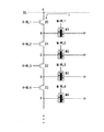
図1は、本発明に係るNAND型磁気抵抗ラムの構成図である。
本発明はビットラインBL、複数のNAND型トランジスタ20〜23及び複数のMTJセルM1〜M4を備える。
【0028】
ここで、複数のNAND型トランジスタ20〜23はノードAとノードEとの間に直列連結され、ソース及びドレイン領域を共有する。複数のMTJセルM1〜M4は、複数のNAND型トランジスタ20〜23の共通ソース及びドレイン領域にそれぞれ連結される。複数のMTJセルM1〜M4の他の一端は接地電圧端と連結される。
【0029】
そして、複数のNAND型トランジスタ20〜23のゲート端子にはこれと一対一に対応するそれぞれの読出しワードラインR−WL1〜R−WL4が連結される。複数のMTJセルM1〜M4は、これと一対一に対応するそれぞれの書込みワードラインW−WL1〜W−WL4と連結される。
【0030】
NAND型に直列連結された複数のトランジスタ20〜23は、それぞれ4つのノードB〜Eを介してMTJセルM1〜M4と連結される。そして、ビットラインBLは1つの読出しノードAと連結される。
【0031】
したがって、NAND型に直列連結された複数のトランジスタ20〜23は、読出しノードのノードAを共有する形を有する。したがって、メモリ素子のセル当りの有効面積を縮小することができ、集積度を向上させることができるようになる。
【0032】
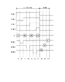
図2は、本発明に係るNAND型磁気抵抗ラムの動作タイミング図を示す図である。
先ず、NAND型磁気抵抗ラムの書込み動作ではそれぞれのMTJセルM1〜M4に連結された書込みワードラインW−WL1〜W−WL4が個別的にイネーブルされる。したがって、一般的なマグネチックラムの場合とその動作過程が同一であるので、その詳細な説明を省略する。
【0033】
一方、読出し動作では直列に連結されたMTJセルM1〜M4に貯蔵されたデータを順次読み出してレジスタ(図示省略)に一時貯蔵する。その後、読出し動作が完了すると、レジスタに貯蔵されたデータを再びMTJセルM1〜M4に順次貯蔵(Re-write)する。ここで、MTJセルM1〜M4から読み出したデータをレジスタに一時的に貯蔵する理由は、読出し動作時にMTJセルM1〜M4のデータを順次読み出すために既に読み出したMTJセルM1〜M4のデータは消去しなければならないためである。
【0034】
図2のタイミング図に示されているように、第1のサイクルのt1では第1のトランジスタ20のゲート端子に連結された読出しワードラインR−WL1がハイにイネーブルされる。第1のトランジスタ20がターンオンされると、ノードBに連結されたMTJセルM1に貯蔵されたデータを読み出す。
【0035】
第2のサイクルのt2では、第1のMTJセルM1に連結された書込みワードラインW−WL1を利用してMTJセルM1にデータ「0」を書き込むことになる。このとき、MTJセルM1のトンネリング接合の抵抗値は、データ「1」が書き込まれたときの小さい抵抗値のRLに比べ非常に大きい抵抗値RHとなる。
【0036】
その後、読出しワードラインR−WL1をハイに維持した状態で、第3のサイクルのt3では第2のMTJセルM2に貯蔵されたデータを読み出す。このため、読出しワードラインR−WL2がハイにイネーブルされると、第2のトランジスタ21がターンオンされてノードCに連結されたMTJセルM2に貯蔵されたデータを読み出す。
【0037】
このとき、ビットラインBLで感知される電流iの大きさは、MTJセルM1及びMTJセルM2の抵抗が並列に連結された形となる。しかし、MTJセルM1の抵抗はt2サイクルで抵抗RHになったため、MTJセルM1及びMTJセルM2の抵抗値はMTJセルM2の抵抗であるR2により影響を受けることになる。
【0038】
各セルのデータを読み出した後はデータを消去する動作が必要であるので、読み出したデータを一時的に貯蔵することができるレジスタが必要である。
【0039】
次に、第4のサイクルのt4では再びMTJセルM2の抵抗をRHにし、第5のサイクルのt5でMTJセルM3に貯蔵された第3のデータを読み出す。このような方式で第7のサイクルのt7まで進められると、4つのMTJセルM1〜M4に貯蔵されたデータを全て読み出すことになる。
【0040】
このとき、最終のMTJセルM4に貯蔵されたデータは読み出した後消去する必要がない。したがって、続くサイクルt8〜t9までの再貯蔵動作ではMTJセルM1〜M3にのみレジスタのデータを再貯蔵すればいい。
【0041】
このようなそれぞれのMTJセルM1〜M4に貯蔵されたデータに対応する電流値を検討してみる。
先ず、MTJセルM1でのビットラインBLの電流は、
【数1】

【0042】
MTJセルM2でのビットラインBLの電流は、
【数2】
【0043】
MTJセルM3でのビットラインBLの電流は、
【数3】
【0044】
MTJセルM4でのビットラインBLの電流は、
【数4】
【0045】
したがって、各MTJセルM1〜M4に貯蔵されたデータに対応する電流値は、次の[表1]に示した通りである(ここで、RH>>RL)。
【表1】
【0046】
このような動作過程を有する本発明に係る書込み動作及び読出し動作は制御手段により制御されるのが好ましく、制御手段の構成は一般的なマグネチックラムの場合と同様であるので、その詳細な説明を省略する。
【0047】
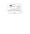
一方、図3は本発明に係るNAND型磁気抵抗ラムの工程断面図である。
複数のトランジスタ20〜23は、P−基板24の上部で非活性領域なくソース及びドレイン領域25を共有して直列に連結される。複数のトランジスタ20〜23のソース及びドレイン領域25には、それぞれのコンタクト領域26を介して複数のMTJセルM1〜M4が連結される。そして、最終段のコンタクト領域26は読出しノードAを介してビットラインBLと連結される。
【0048】
さらに、複数のトランジスタ20〜23はゲート上部には読出しワードラインR−WL1〜R−WL4がそれぞれ形成される。それぞれのMTJセルM1〜M4の上部には接地線27と連結される。そして、接地線27の上部にはMTJセルM1〜M4にデータを書き込むための書込みワードラインW−WL1〜W−WL4がビットラインBLと直角に形成される。
【0049】
このとき、書込みワードラインW−WL1〜W−WL4とビットラインBLが直角に交差する位置に存在するMTJセルM1〜M4に加えられるフィールドの大きさが最大になるので、該当MTJセルM1〜M4にデータを書き込むことができるようになる。
【0050】
【発明の効果】
前述のように、本発明は複数のセルが1つのノードを共有し、複数のトランジスタを直列に連結して非活性領域を減少させることができる。したがって、セル当りの有効面積が減少し、素子の集積度を向上させることができるようになる効果がある。
【図面の簡単な説明】
【図1】本発明に係るNAND型磁気抵抗ラムの構成を示す図である。
【図2】本発明に係るNAND型磁気抵抗ラムの動作タイミング図である。
【図3】本発明に係るNAND型磁気抵抗ラムの断面図である。
【図4】従来のMTJセルの断面図である。
【図5】従来の水平構造電界効果トランジスタを利用した磁気抵抗ラムの模式図である。
【図6】従来の水平構造電界効果トランジスタを利用した磁気抵抗ラムの断面図である。
【符号の説明】
20〜23 NAND型トランジスタ
24 P−基板
25 ソース及びドレイン領域
26 コンタクト領域
27 接地線[0001]
TECHNICAL FIELD OF THE INVENTION
The present invention relates to a NAND type magnetoresistive ram, and more particularly, to a NAND type magnetoresistive ram capable of improving a cell structure of the magnetoresistive ram to reduce an effective area per cell and improve a degree of integration.
[0002]
[Prior art]
At present, most semiconductor memory manufacturers and the like are actively participating in the development of a magnetoresistive ram using a ferromagnetic material as one of the next-generation storage elements.
[0003]
The magnetoresistive ram is a storage element that can read and write data by forming a ferromagnetic thin film in multiple layers and sensing a current change accompanying the magnetization direction of each thin film layer. Such a magnetoresistive ram is an element capable of high-speed, low-power and high-integration due to the inherent characteristics of the magnetic thin film, and capable of operating in a non-volatile memory like a flash memory.
[0004]
Research on this is currently in the early stages and is mainly focused on the formation of multilayer magnetic thin films. Research on the structure of the unit cell and the peripheral sensing circuit is still incomplete.
[0005]
FIG. 4 is a cross-sectional view of an MTJ (Magnetic Tunnel Junction, Magnetic Tunnel Junction) cell having such a conventional multilayered magnetic thin film structure of a magnetoresistive ram.
Generally, the MTJ
[0006]
Here, the magnetization direction of the fixed-layer ferromagnetic
[0007]
When a current flows in such a vertical direction of the
[0008]
Such a phenomenon is called TMR (Tunneling Magnetoresistance) effect. By sensing the magnitude of the tunneling current, the magnetization direction of the free layer ferromagnetic
[0009]
FIG. 5 is a diagram showing an embodiment in which a cell of a magnetoresistive ram is realized using a field effect transistor (Field Effect Transistor).
The unit cell of the magnetoresistive ram includes one horizontal-structure field effect transistor (Metal-Oxide-Silicon Field Effect Transistor) 9, MTJ
[0010]
Here, the
[0011]
The conventional magnetoresistive ram having such a configuration operates the field effect transistor 9 by applying a voltage to the
[0012]
Further, at the time of writing, a current is applied to the
[0013]
Here, the reason why the current is applied to the bit line 7 and the
[0014]
FIG. 6 is a sectional view of a magnetoresistive ram corresponding to the conventional magnetoresistive ram cell of FIG.
As shown in FIG. 6, the
[0015]
[Problems to be solved by the invention]
However, in such a conventional magnetoresistive ram, one transistor and a corresponding MTJ cell, a read word line, a write word line, and a bit line constitute one cell. Therefore, there is a problem that the effective area occupied by the cell increases and the integration degree of the memory device decreases.
[0016]
SUMMARY OF THE INVENTION The present invention has been made to solve the above-described problems. Two or more transistors sharing a source and a drain region are connected in a NAND type, and one read node connected to a bit line is connected. It is an object of the present invention to reduce the effective area per cell and improve the degree of integration by configuring a plurality of transistors to share.
[0017]
[Means for Solving the Problems]
To achieve the above object, the invention according to
A plurality of transistors, each having a gate to which a read word line assigned thereto is connected, and serially connected in a NAND type;
A bit line connected to a vertical transistor among the plurality of transistors connected in series via one read node, and each bit line is connected to a connection node of the plurality of transistors one by one and controlled by a respective write word line. A plurality of MTJ cells.
[0018]
According to a second aspect of the present invention, in the first aspect, a register for temporarily storing data sequentially read from the plurality of MTJ cells in the read mode is further provided.
[0019]
According to a third aspect of the present invention, in the second aspect, in the read mode, data sequentially read from the plurality of MTJ cells is erased, and when the read mode is completed, the data stored in the register is replaced with the plurality of MTJ cells. The apparatus is further characterized by further comprising control means for sequentially storing the data in the cell again.
[0020]
According to a fourth aspect of the present invention, in the third aspect, the control means maintains the data stored in the last MTJ cell among the plurality of MTJ cells without erasing the data after reading, and Is characterized by being maintained without re-storage.
[0021]
According to a fifth aspect of the present invention, in the third aspect, the control means performs control such that a read word line connected to a gate terminal of a transistor adjacent to the read node is sequentially enabled, and a final transistor is turned on. The control is performed so as to maintain the enabled state until it is performed.
[0022]
According to a sixth aspect of the present invention, in the third aspect, the control means controls the respective write word lines connected to the plurality of MTJ cells to be individually enabled in a write mode. And
[0023]
The invention according to claim 7 is characterized in that, in
[0024]
The invention according to
A plurality of transistors formed on the P-substrate and sharing adjacent source and drain regions and connected in series in a NAND type;
A plurality of read word lines formed above gate regions of the plurality of transistors;
A plurality of MTJ cells respectively connected to a connection node between the plurality of transistors;
A ground line commonly formed on the plurality of MTJ cells,
A plurality of write word lines formed above the ground line and respectively corresponding to the plurality of MTJ cells, and connected to a vertical transistor among the plurality of transistors via one read node; A bit line is formed on the upper part.
[0025]
According to a ninth aspect of the present invention, in the ninth aspect, the semiconductor device further includes a plurality of contact regions connecting the source and drain regions of the plurality of transistors and the plurality of MTJ cells.
[0026]
According to a tenth aspect of the present invention, in the eighth aspect,
The semiconductor device may further include a contact region formed above source and drain regions of the transistors formed at the ends of the plurality of transistors, and the read node formed above the contact region and connected to the bit line. Features.
[0027]
BEST MODE FOR CARRYING OUT THE INVENTION
Hereinafter, an embodiment of the present invention will be described with reference to FIGS.
FIG. 1 is a configuration diagram of a NAND type magnetoresistive ram according to the present invention.
The present invention includes a bit line BL, a plurality of
[0028]
Here, the plurality of
[0029]
The gate terminals of the plurality of
[0030]
The plurality of
[0031]
Therefore, the plurality of
[0032]
FIG. 2 is a diagram showing an operation timing chart of the NAND type magnetoresistive ram according to the present invention.
First, in the write operation of the NAND type magnetoresistive ram, the write word lines W-WL1 to W-WL4 connected to the respective MTJ cells M1 to M4 are individually enabled. Therefore, since the operation process is the same as that of a general magnetic ram, a detailed description thereof will be omitted.
[0033]
On the other hand, in the read operation, data stored in the serially connected MTJ cells M1 to M4 is sequentially read and temporarily stored in a register (not shown). Thereafter, when the read operation is completed, the data stored in the register is sequentially stored (re-written) again in the MTJ cells M1 to M4. Here, the reason why the data read from the MTJ cells M1 to M4 is temporarily stored in the register is that the data of the MTJ cells M1 to M4 that have already been read in order to sequentially read the data of the MTJ cells M1 to M4 during the read operation are erased. Because you have to do it.
[0034]
As shown in the timing diagram of FIG. 2, the read word line R-WL1 connected to the gate terminal of the
[0035]
At t2 of the second cycle, data “0” is written to the MTJ cell M1 using the write word line W-WL1 connected to the first MTJ cell M1. At this time, the resistance value of the tunneling junction MTJ cell M1 is a very large resistance value R H compared to R L of less resistance when data "1" is written.
[0036]
Thereafter, while the read word line R-WL1 is maintained at a high level, the data stored in the second MTJ cell M2 is read at the third cycle t3. Therefore, when the read word line R-WL2 is enabled to a high level, the
[0037]
At this time, the magnitude of the current i sensed by the bit line BL is such that the resistances of the MTJ cells M1 and M2 are connected in parallel. However, since the resistance of the MTJ cell M1 becomes the resistance RH in the t2 cycle, the resistance values of the MTJ cell M1 and the MTJ cell M2 are affected by the resistance R2 of the MTJ cell M2.
[0038]
After the data of each cell is read, an operation of erasing the data is required. Therefore, a register capable of temporarily storing the read data is required.
[0039]
Next, at t4 in the fourth cycle, the resistance of the MTJ cell M2 is set to RH again, and at t5 in the fifth cycle, the third data stored in the MTJ cell M3 is read. When the operation is advanced to t7 in the seventh cycle in this manner, all the data stored in the four MTJ cells M1 to M4 are read.
[0040]
At this time, there is no need to erase the data stored in the final MTJ cell M4 after reading it. Therefore, in the subsequent re-storage operation from cycle t8 to t9, the data of the register only needs to be re-stored in the MTJ cells M1 to M3.
[0041]
Consider a current value corresponding to data stored in each of the MTJ cells M1 to M4.
First, the current of the bit line BL in the MTJ cell M1 is
(Equation 1)
[0042]
The current of the bit line BL in the MTJ cell M2 is
(Equation 2)
[0043]
The current of the bit line BL in the MTJ cell M3 is
[Equation 3]
[0044]
The current of the bit line BL in the MTJ cell M4 is
(Equation 4)
[0045]
Therefore, the current values corresponding to the data stored in the MTJ cells M1 to M4 are as shown in Table 1 below (here, RH >> RL ).
[Table 1]
[0046]
It is preferable that the write operation and the read operation according to the present invention having such an operation process are controlled by the control unit, and the configuration of the control unit is the same as that of a general magnetic ram. Is omitted.
[0047]
On the other hand, FIG. 3 is a process sectional view of the NAND type magnetoresistive ram according to the present invention.
The plurality of
[0048]
In addition, readout word lines R-WL1 to R-WL4 are formed above the gates of the
[0049]
At this time, the size of the field added to the MTJ cells M1 to M4 existing at the position where the write word lines W-WL1 to W-WL4 and the bit line BL intersect at right angles is maximized. Data can be written to the
[0050]
【The invention's effect】
As described above, in the present invention, a plurality of cells share one node, and a plurality of transistors are connected in series to reduce an inactive region. Accordingly, there is an effect that the effective area per cell is reduced and the degree of integration of the element can be improved.
[Brief description of the drawings]
FIG. 1 is a diagram showing a configuration of a NAND type magnetoresistive ram according to the present invention.
FIG. 2 is an operation timing chart of the NAND type magnetoresistive ram according to the present invention.
FIG. 3 is a sectional view of a NAND type magnetoresistive ram according to the present invention.
FIG. 4 is a cross-sectional view of a conventional MTJ cell.
FIG. 5 is a schematic diagram of a magnetoresistive ram using a conventional horizontal structure field effect transistor.
FIG. 6 is a cross-sectional view of a magnetoresistive ram using a conventional horizontal structure field effect transistor.
[Explanation of symbols]
20-23 NAND type transistor 24 P-substrate 25 Source and drain
Claims (10)
前記直列連結された複数のトランジスタのうち縦断トランジスタと1つの読出しノードを介して連結されたビットライン、及び
それぞれが前記複数のトランジスタの連結ノードに1つずつ連結され、それぞれの書込みワードラインにより制御される複数のMTJセルを備えることを特徴とするNAND型磁気抵抗ラム。A plurality of transistors, each having a gate to which a read word line assigned thereto is connected, and serially connected in a NAND type;
A bit line connected to a vertical transistor among the plurality of transistors connected in series via one read node, and each bit line is connected to a connection node of the plurality of transistors one by one and controlled by a respective write word line. Characterized by comprising a plurality of MTJ cells.
前記複数のトランジスタのゲート領域の上部に形成された複数の読出しワードライン、
前記複数のトランジスタ間の連結ノードにそれぞれ連結された複数のMTJセル、
前記複数のMTJセルの上部に共通に形成された接地ライン、
前記接地ラインの上部に形成され前記複数のMTJセルにそれぞれ対応する複数の書込みワードライン、及び
前記複数のトランジスタのうち縦断トランジスタと1つの読出しノードを介して連結され、前記複数の書込みワードラインの上部に形成されるビットラインを備えることを特徴とするNAND型磁気抵抗ラム。A plurality of transistors formed on the P-substrate and sharing adjacent source and drain regions and connected in series in a NAND type;
A plurality of read word lines formed above gate regions of the plurality of transistors;
A plurality of MTJ cells respectively connected to a connection node between the plurality of transistors;
A ground line commonly formed on the plurality of MTJ cells,
A plurality of write word lines formed above the ground line and respectively corresponding to the plurality of MTJ cells, and connected to a vertical transistor among the plurality of transistors via one read node; A NAND type magnetoresistive ram comprising a bit line formed on an upper part thereof.
前記コンタクト領域の上部に形成され、前記ビットラインと連結された前記読出しノードをさらに備えることを特徴とする請求項8に記載のNAND型磁気抵抗ラム。The semiconductor device may further include a contact region formed above source and drain regions of the transistors formed at the ends of the plurality of transistors, and the read node formed above the contact region and connected to the bit line. The NAND type magnetoresistive ram according to claim 8, wherein:
Applications Claiming Priority (2)
| Application Number | Priority Date | Filing Date | Title |
|---|---|---|---|
| KR10-2002-0080181A KR100506060B1 (en) | 2002-12-16 | 2002-12-16 | NAND type magnetoresistive random access memory |
| KR2002-80181 | 2002-12-16 |
Publications (2)
| Publication Number | Publication Date |
|---|---|
| JP2004200641A true JP2004200641A (en) | 2004-07-15 |
| JP4837246B2 JP4837246B2 (en) | 2011-12-14 |
Family
ID=32501424
Family Applications (1)
| Application Number | Title | Priority Date | Filing Date |
|---|---|---|---|
| JP2003187061A Expired - Fee Related JP4837246B2 (en) | 2002-12-16 | 2003-06-30 | NAND magnetoresistive ram |
Country Status (3)
| Country | Link |
|---|---|
| US (1) | US6885578B2 (en) |
| JP (1) | JP4837246B2 (en) |
| KR (1) | KR100506060B1 (en) |
Cited By (4)
| Publication number | Priority date | Publication date | Assignee | Title |
|---|---|---|---|---|
| WO2006095389A1 (en) * | 2005-03-04 | 2006-09-14 | Fujitsu Limited | Magnetic memory and read/write method thereof |
| WO2009028297A1 (en) * | 2007-08-31 | 2009-03-05 | Tokyo Institute Of Technology | Electronic circuit |
| WO2010109803A1 (en) * | 2009-03-25 | 2010-09-30 | パナソニック株式会社 | Resistance-change non-volatile memory device |
| WO2011052292A1 (en) * | 2009-10-26 | 2011-05-05 | Jsr株式会社 | Memory circuit, integrated circuit device and electronic device |
Families Citing this family (7)
| Publication number | Priority date | Publication date | Assignee | Title |
|---|---|---|---|---|
| KR100817061B1 (en) * | 2006-09-26 | 2008-03-27 | 삼성전자주식회사 | Magnetoresistive ram flowing inhibition current in the same direction as write current |
| EP2084710B1 (en) * | 2006-12-29 | 2018-08-22 | SanDisk Technologies LLC | Resistance sensing and compensation for non-volatile storage |
| US8331126B2 (en) * | 2010-06-28 | 2012-12-11 | Qualcomm Incorporated | Non-volatile memory with split write and read bitlines |
| CN110890394B (en) * | 2018-09-07 | 2022-07-26 | 联华电子股份有限公司 | Magnetoresistive random access memory |
| CN113497082A (en) * | 2020-03-18 | 2021-10-12 | 上海磁宇信息科技有限公司 | Magnetic random access memory architecture |
| US11164610B1 (en) | 2020-06-05 | 2021-11-02 | Qualcomm Incorporated | Memory device with built-in flexible double redundancy |
| US11177010B1 (en) | 2020-07-13 | 2021-11-16 | Qualcomm Incorporated | Bitcell for data redundancy |
Citations (4)
| Publication number | Priority date | Publication date | Assignee | Title |
|---|---|---|---|---|
| JPH0773666A (en) * | 1993-09-02 | 1995-03-17 | Toshiba Corp | Dynamic semiconductor memory |
| JPH0991949A (en) * | 1995-09-22 | 1997-04-04 | Tdk Corp | Magnetic thin-film memory element and magnetic thin-film memory |
| JP2000132961A (en) * | 1998-10-23 | 2000-05-12 | Canon Inc | Magnetic thin film memory, method for reading out magnetic thin film memory, and method for writing to magnetic thin film memory |
| JP2002344041A (en) * | 2001-05-15 | 2002-11-29 | Matsushita Electric Ind Co Ltd | Tunnel junction element and manufacturing method therefor |
Family Cites Families (4)
| Publication number | Priority date | Publication date | Assignee | Title |
|---|---|---|---|---|
| JP3920564B2 (en) * | 2000-12-25 | 2007-05-30 | 株式会社東芝 | Magnetic random access memory |
| JP4073690B2 (en) * | 2001-11-14 | 2008-04-09 | 株式会社ルネサステクノロジ | Thin film magnetic memory device |
| JP2003151262A (en) * | 2001-11-15 | 2003-05-23 | Toshiba Corp | Magnetic random access memory |
| EP1321944B1 (en) * | 2001-12-21 | 2008-07-30 | Kabushiki Kaisha Toshiba | Magnetic random access memory |
-
2002
- 2002-12-16 KR KR10-2002-0080181A patent/KR100506060B1/en not_active IP Right Cessation
-
2003
- 2003-06-30 JP JP2003187061A patent/JP4837246B2/en not_active Expired - Fee Related
- 2003-06-30 US US10/608,195 patent/US6885578B2/en not_active Expired - Lifetime
Patent Citations (4)
| Publication number | Priority date | Publication date | Assignee | Title |
|---|---|---|---|---|
| JPH0773666A (en) * | 1993-09-02 | 1995-03-17 | Toshiba Corp | Dynamic semiconductor memory |
| JPH0991949A (en) * | 1995-09-22 | 1997-04-04 | Tdk Corp | Magnetic thin-film memory element and magnetic thin-film memory |
| JP2000132961A (en) * | 1998-10-23 | 2000-05-12 | Canon Inc | Magnetic thin film memory, method for reading out magnetic thin film memory, and method for writing to magnetic thin film memory |
| JP2002344041A (en) * | 2001-05-15 | 2002-11-29 | Matsushita Electric Ind Co Ltd | Tunnel junction element and manufacturing method therefor |
Cited By (8)
| Publication number | Priority date | Publication date | Assignee | Title |
|---|---|---|---|---|
| WO2006095389A1 (en) * | 2005-03-04 | 2006-09-14 | Fujitsu Limited | Magnetic memory and read/write method thereof |
| JPWO2006095389A1 (en) * | 2005-03-04 | 2008-08-14 | 富士通株式会社 | Magnetic memory device and reading method and writing method thereof |
| WO2009028297A1 (en) * | 2007-08-31 | 2009-03-05 | Tokyo Institute Of Technology | Electronic circuit |
| WO2010109803A1 (en) * | 2009-03-25 | 2010-09-30 | パナソニック株式会社 | Resistance-change non-volatile memory device |
| JP4606520B2 (en) * | 2009-03-25 | 2011-01-05 | パナソニック株式会社 | Variable resistance nonvolatile memory device |
| JPWO2010109803A1 (en) * | 2009-03-25 | 2012-09-27 | パナソニック株式会社 | Variable resistance nonvolatile memory device |
| US8320159B2 (en) | 2009-03-25 | 2012-11-27 | Panasonic Corporation | Resistance variable nonvolatile memory device |
| WO2011052292A1 (en) * | 2009-10-26 | 2011-05-05 | Jsr株式会社 | Memory circuit, integrated circuit device and electronic device |
Also Published As
| Publication number | Publication date |
|---|---|
| US20040113187A1 (en) | 2004-06-17 |
| US6885578B2 (en) | 2005-04-26 |
| KR20040052322A (en) | 2004-06-23 |
| KR100506060B1 (en) | 2005-08-05 |
| JP4837246B2 (en) | 2011-12-14 |
Similar Documents
| Publication | Publication Date | Title |
|---|---|---|
| JP5677187B2 (en) | Semiconductor memory device | |
| TW518597B (en) | MRAM-arrangement | |
| JP4566550B2 (en) | Magnetic ram element having reference cell and structure thereof | |
| US20030128580A1 (en) | High-density magnetic random access memory device and method of operating the same | |
| TW200401296A (en) | Shared volatile and non-volatile memory | |
| JP2009260364A (en) | Semiconductor memory device | |
| JP2002230965A (en) | Non-volatile memory device | |
| KR20120058425A (en) | Magnetic memory cell with multi-level cellmlc data storage capability | |
| US6822897B2 (en) | Thin film magnetic memory device selecting access to a memory cell by a transistor of a small gate capacitance | |
| JP2006190432A (en) | Nonvolatile ferroelectric memory device | |
| KR100697140B1 (en) | Magnetic random access memory | |
| US7688623B2 (en) | Magnetic memory cell and magnetic memory device | |
| JP4837246B2 (en) | NAND magnetoresistive ram | |
| US9318178B2 (en) | Semiconductor storage device and data processing method | |
| JPH11306750A (en) | Magnetic-type semiconductor integrated storage | |
| US20050052902A1 (en) | Memory device with a thermally assisted write | |
| JP2016167333A (en) | Pseudo page mode memory architecture and method | |
| US7304887B2 (en) | Method and apparatus for multi-plane MRAM | |
| KR100546177B1 (en) | Magnetoresistive ram | |
| US20220263011A1 (en) | Mram cell and mram | |
| TW202013362A (en) | Semiconductor memory device including a memory area including a plurality of memory cells and a controller that reads out the read data stored in the memory cells | |
| US7102917B2 (en) | Memory array method and system | |
| JP4726169B2 (en) | Magnetic memory and driving method thereof | |
| KR100680422B1 (en) | Magnetic random access memory | |
| CN117479548A (en) | Magnetic memory array, preparation method thereof, data access method and electronic equipment |
Legal Events
| Date | Code | Title | Description |
|---|---|---|---|
| A621 | Written request for application examination |
Free format text: JAPANESE INTERMEDIATE CODE: A621 Effective date: 20060313 |
|
| A977 | Report on retrieval |
Free format text: JAPANESE INTERMEDIATE CODE: A971007 Effective date: 20091109 |
|
| A131 | Notification of reasons for refusal |
Free format text: JAPANESE INTERMEDIATE CODE: A131 Effective date: 20091201 |
|
| A521 | Request for written amendment filed |
Free format text: JAPANESE INTERMEDIATE CODE: A523 Effective date: 20100301 |
|
| A131 | Notification of reasons for refusal |
Free format text: JAPANESE INTERMEDIATE CODE: A131 Effective date: 20110104 |
|
| A521 | Request for written amendment filed |
Free format text: JAPANESE INTERMEDIATE CODE: A523 Effective date: 20110401 |
|
| TRDD | Decision of grant or rejection written | ||
| A01 | Written decision to grant a patent or to grant a registration (utility model) |
Free format text: JAPANESE INTERMEDIATE CODE: A01 Effective date: 20110906 |
|
| A01 | Written decision to grant a patent or to grant a registration (utility model) |
Free format text: JAPANESE INTERMEDIATE CODE: A01 |
|
| A61 | First payment of annual fees (during grant procedure) |
Free format text: JAPANESE INTERMEDIATE CODE: A61 Effective date: 20110928 |
|
| FPAY | Renewal fee payment (event date is renewal date of database) |
Free format text: PAYMENT UNTIL: 20141007 Year of fee payment: 3 |
|
| R150 | Certificate of patent or registration of utility model |
Free format text: JAPANESE INTERMEDIATE CODE: R150 |
|
| LAPS | Cancellation because of no payment of annual fees |