JP2004200348A - Diagnostic method of oil filled transformer by analysis of gas-in-oil - Google Patents
Diagnostic method of oil filled transformer by analysis of gas-in-oil Download PDFInfo
- Publication number
- JP2004200348A JP2004200348A JP2002366172A JP2002366172A JP2004200348A JP 2004200348 A JP2004200348 A JP 2004200348A JP 2002366172 A JP2002366172 A JP 2002366172A JP 2002366172 A JP2002366172 A JP 2002366172A JP 2004200348 A JP2004200348 A JP 2004200348A
- Authority
- JP
- Japan
- Prior art keywords
- oil
- gas
- diagnosis
- equivalent
- analysis
- Prior art date
- Legal status (The legal status is an assumption and is not a legal conclusion. Google has not performed a legal analysis and makes no representation as to the accuracy of the status listed.)
- Granted
Links
- 238000004458 analytical method Methods 0.000 title claims abstract description 34
- 238000002405 diagnostic procedure Methods 0.000 title description 10
- XEEYBQQBJWHFJM-UHFFFAOYSA-N Iron Chemical group [Fe] XEEYBQQBJWHFJM-UHFFFAOYSA-N 0.000 claims abstract description 47
- 230000005856 abnormality Effects 0.000 claims abstract description 47
- 230000002159 abnormal effect Effects 0.000 claims abstract description 34
- 238000004868 gas analysis Methods 0.000 claims abstract description 22
- VGGSQFUCUMXWEO-UHFFFAOYSA-N Ethene Chemical compound C=C VGGSQFUCUMXWEO-UHFFFAOYSA-N 0.000 claims abstract description 12
- 239000005977 Ethylene Substances 0.000 claims abstract description 12
- OTMSDBZUPAUEDD-UHFFFAOYSA-N Ethane Chemical compound CC OTMSDBZUPAUEDD-UHFFFAOYSA-N 0.000 claims abstract description 8
- 238000003745 diagnosis Methods 0.000 claims description 55
- 238000004804 winding Methods 0.000 claims description 47
- 238000010586 diagram Methods 0.000 claims description 34
- 238000000034 method Methods 0.000 claims description 23
- 238000012544 monitoring process Methods 0.000 claims description 12
- 238000004891 communication Methods 0.000 claims description 3
- 238000013021 overheating Methods 0.000 abstract description 29
- 238000004519 manufacturing process Methods 0.000 abstract description 3
- 239000007789 gas Substances 0.000 description 87
- 239000003921 oil Substances 0.000 description 45
- UGFAIRIUMAVXCW-UHFFFAOYSA-N Carbon monoxide Chemical compound [O+]#[C-] UGFAIRIUMAVXCW-UHFFFAOYSA-N 0.000 description 16
- 229910002091 carbon monoxide Inorganic materials 0.000 description 16
- 238000012423 maintenance Methods 0.000 description 14
- 238000002474 experimental method Methods 0.000 description 13
- 238000007726 management method Methods 0.000 description 12
- VNWKTOKETHGBQD-UHFFFAOYSA-N methane Chemical compound C VNWKTOKETHGBQD-UHFFFAOYSA-N 0.000 description 10
- 238000011160 research Methods 0.000 description 7
- 239000000203 mixture Substances 0.000 description 6
- 238000007689 inspection Methods 0.000 description 5
- 229910052742 iron Inorganic materials 0.000 description 5
- CURLTUGMZLYLDI-UHFFFAOYSA-N Carbon dioxide Chemical compound O=C=O CURLTUGMZLYLDI-UHFFFAOYSA-N 0.000 description 4
- 229910000976 Electrical steel Inorganic materials 0.000 description 3
- WABPQHHGFIMREM-UHFFFAOYSA-N lead(0) Chemical compound [Pb] WABPQHHGFIMREM-UHFFFAOYSA-N 0.000 description 3
- 239000000463 material Substances 0.000 description 3
- 229930195735 unsaturated hydrocarbon Natural products 0.000 description 3
- RYGMFSIKBFXOCR-UHFFFAOYSA-N Copper Chemical compound [Cu] RYGMFSIKBFXOCR-UHFFFAOYSA-N 0.000 description 2
- HSFWRNGVRCDJHI-UHFFFAOYSA-N alpha-acetylene Natural products C#C HSFWRNGVRCDJHI-UHFFFAOYSA-N 0.000 description 2
- 230000005540 biological transmission Effects 0.000 description 2
- 229910002092 carbon dioxide Inorganic materials 0.000 description 2
- 239000001569 carbon dioxide Substances 0.000 description 2
- 238000007796 conventional method Methods 0.000 description 2
- 238000000354 decomposition reaction Methods 0.000 description 2
- 230000000694 effects Effects 0.000 description 2
- 125000002534 ethynyl group Chemical group [H]C#C* 0.000 description 2
- 238000010438 heat treatment Methods 0.000 description 2
- 239000001257 hydrogen Substances 0.000 description 2
- 229910052739 hydrogen Inorganic materials 0.000 description 2
- 125000004435 hydrogen atom Chemical class [H]* 0.000 description 2
- 238000005070 sampling Methods 0.000 description 2
- IJGRMHOSHXDMSA-UHFFFAOYSA-N Atomic nitrogen Chemical compound N#N IJGRMHOSHXDMSA-UHFFFAOYSA-N 0.000 description 1
- QVGXLLKOCUKJST-UHFFFAOYSA-N atomic oxygen Chemical compound [O] QVGXLLKOCUKJST-UHFFFAOYSA-N 0.000 description 1
- 239000004020 conductor Substances 0.000 description 1
- 238000013016 damping Methods 0.000 description 1
- 238000007405 data analysis Methods 0.000 description 1
- 238000013480 data collection Methods 0.000 description 1
- 238000010891 electric arc Methods 0.000 description 1
- 238000005516 engineering process Methods 0.000 description 1
- 230000003628 erosive effect Effects 0.000 description 1
- 238000010348 incorporation Methods 0.000 description 1
- 238000009413 insulation Methods 0.000 description 1
- 238000012806 monitoring device Methods 0.000 description 1
- 239000001301 oxygen Substances 0.000 description 1
- 229910052760 oxygen Inorganic materials 0.000 description 1
- 229930195734 saturated hydrocarbon Natural products 0.000 description 1
- 238000012360 testing method Methods 0.000 description 1
- 238000005979 thermal decomposition reaction Methods 0.000 description 1
Images


Classifications
-
- G—PHYSICS
- G01—MEASURING; TESTING
- G01N—INVESTIGATING OR ANALYSING MATERIALS BY DETERMINING THEIR CHEMICAL OR PHYSICAL PROPERTIES
- G01N33/00—Investigating or analysing materials by specific methods not covered by groups G01N1/00 - G01N31/00
- G01N33/26—Oils; Viscous liquids; Paints; Inks
- G01N33/28—Oils, i.e. hydrocarbon liquids
- G01N33/2835—Specific substances contained in the oils or fuels
- G01N33/2841—Gas in oils, e.g. hydrogen in insulating oils
Landscapes
- Chemical & Material Sciences (AREA)
- Health & Medical Sciences (AREA)
- Engineering & Computer Science (AREA)
- Life Sciences & Earth Sciences (AREA)
- Medicinal Chemistry (AREA)
- Biochemistry (AREA)
- General Chemical & Material Sciences (AREA)
- Food Science & Technology (AREA)
- Chemical Kinetics & Catalysis (AREA)
- Physics & Mathematics (AREA)
- Analytical Chemistry (AREA)
- Oil, Petroleum & Natural Gas (AREA)
- General Health & Medical Sciences (AREA)
- General Physics & Mathematics (AREA)
- Immunology (AREA)
- Pathology (AREA)
- Testing Electric Properties And Detecting Electric Faults (AREA)
- Housings And Mounting Of Transformers (AREA)
Abstract
Description
【0001】
【発明の属する技術分野】
本発明は、油入変圧器の油中ガスを分析することによって変圧器の異常の有無を判断する診断方法に関するものである。
【0002】
【従来の技術】
油入変圧器の保守管理技術の一環として、油中ガス分析を適用して変圧器の異常の有無と診断を行う方法があり、この方法は変圧器の運転中の状態で容易に行えることで実用化され、稼働中の変圧器に適用されて事故防止に役立っている。
【0003】
油中ガス分析による保守管理の方法は、変圧器の内部に異常があって放電や過熱が発生していると、絶縁油が分解して分解ガスを発生しているので、その絶縁油を採油して絶縁油中に含まれるガス成分を分析することによって異常を診断するものである。
その際、油中ガス分析による保守管理基準としては、電気協同研究会第54巻第5号(その1)油入変圧器の保守管理にまとめられており、電力会社他多数のユーザーでこの指針に基づいて運用されている。
【0004】
ガス成分としては窒素(N2)、酸素(O2)、水素(H2)、メタン(CH4)、エタン(C2H6)、エチレン(C2H4)、アセチレン(C2H2)、一酸化炭素(CO)、二酸化炭素(CO2)が用いられ、各ガス成分の量を分析して診断に用いている。
前記の各ガスのうちH2,CH4,C2H6,C2H4,C2H2,COの和を可燃性ガス総量(Total Combustible Gas:TCG)といい、放電や過熱などの異常により油が分解して発生するガス量として管理指標に用いられている。
【0005】
電気協同研究会の保守管理基準(非特許文献1)では、油中ガス分析結果から特定ガスの絶対量・増加量により、変圧器の状態を正常、要注意1、要注意2、異常のレベルにランク分けして図13の診断フローにより管理している。
油中ガス分析結果から、図13で明らかなように異常の箇所、異常の程度、および緊急性を判断するために以下の様相診断の方法が規定されている。
(1)、ガスパターンによる診断(様相診断1)
(2)、組成比(異常診断図)による診断(様相診断2)
(3)、特定ガスによる診断(様相診断3)
(1)のガスパターンによる診断方法は、横軸に対象ガスを、縦軸には各ガスの最大値を1とし(最大値を示すガスを主導ガスと呼んでいる)、それに対する比率をプロットしてパターン図を描いてその形状により異常の内容を診断するものである。変圧器内部の異常が放電と過熱ではガスパターンが異なることが知られており、ガスパターンにより異常部位の様相を診断するものである。
【0006】
(2)の組成比による診断方法は、特定ガスとしてのC2H2,C2H4とC2H6のガス量の比率から異常現象の内容を判断するもので、異常診断表や異常診断図としてまとめられている。
異常診断図はC2H4/C2H6の比率を横軸に、縦軸にC2H2/C2H4およびC2H2/C2H6の比率をプロットして診断を行うもので、放電と過熱の判別や放電のうちアーク放電と部分放電を区別することができる。
【0007】
(3)の特定ガスによる診断は、異常内容を診断する上で極めて特定なガスに着目して診断する方法で、その代表的なガスとしてCO,CO2,C2H2などを適用する。例えば絶縁紙が過熱する場合には炭酸ガスの発生割合が多くなるのでCO2/CO≦3の場合には絶縁紙が過熱していると診断する。
【0008】
【非特許文献1】
社団法人 電気協同研究会「電気協同研究」第54巻第5号(その1)
油入変圧器の保守管理 発行 平成12年2月
【0009】
【非特許文献2】
「絶縁油の局部過熱による分解ガスの挙動」月岡他(電気学会論文誌A98巻7号昭和53年)
【0010】
【発明が解決しようとする課題】
油入変圧器の保守管理の面からは、油中ガス分析により異常が検出された場合、どの箇所でどの程度の異常があり今後どうなるかが重要であり、特に鉄心系の異常(変圧器を構成する鉄心や構造材で発生するもので、異常箇所が主回路と電気的回路に接続されていないため、直接変圧器の停止に結びつかない異常)と巻線系の異常(主に変圧器を構成する巻線に関するもので、常時電圧が印加され負荷電流も流れる箇所であり、電気的事故につながり直ちに停止に至る異常)を的確に判別する必要がある。
【0011】
しかしながら、従来における鉄心系と巻線系の異常箇所判別の手法は、前述した(1)〜(3)の診断方法であり、水素(H2)やアセチレン(C2H2)主導のガスパターン、組成比(異常診断図)で放電の領域、CO,CO2などの特定ガスが発生すれば、巻線系の放電による異常の可能性が判断できるが、比較的低エネルギーの過熱による異常場合には、的確な判断は困難となっている。
【0012】
また、ガスパターンによる診断方法では、過熱モードの異常によるガスパターンは、図14〜図16に示すように鉄心系、巻線系ともエチレンやメタン主導のガスパターンであり、巻線系の異常を鉄心系の過熱の可能性が高いと誤って判断された事例も出てきている。
【0013】
また、異常診断図では、異常の様相が放電か過熱かの判別を行うものであり、過熱モードの異常については過熱温度の高低や放電が含まれているかの判別はできるが、異常箇所が巻線系のものか鉄心系のものかの判別は難しい。実際の診断例でも図17のように、エネルギーの大きな放電の判別はできるが、過熱モードでは鉄心系の異常と巻線系の異常では同じ領域にプロットされる例が多く判別が困難である。
この理由は、過熱による分解ガスの発生は絶縁油を構成している分子が分解してガス化するものであり、過熱部の温度により分解ガスの成分は変化するが、異常部位の材料の違いによる影響は少ないためと考えられる。
【0014】
特定ガスによる診断では、巻線の絶縁紙過熱の診断指標としてCO,CO2を用いているが、過熱が局部である場合、CO,CO2の発生量が僅かであり、通常運転により変圧器全体の絶縁紙から発生するCO,CO2に隠れてしまい、特に大容量器では巻線系と鉄心系の判別が困難となっている。
【0015】
電気協同研究第54巻第5号(その1)油入変圧器の保守管理(非特許文献1)では、油中分解ガスの発生原理について理論的にまとめ、過去の文献を用いて異常箇所の過熱温度や過熱面積を推定できると記載されている。
過熱温度については、絶縁油の過熱による発生ガスは温度が変わると組成が変化し、温度が高くなるほど不飽和炭化水素の割合が多くなるので、図18に示すように発生ガス中の飽和炭化水素と不飽和炭化水素の比から熱分解温度を推定できる。
また、ガスの生成速度は温度が高くなるほど速くなり、過熱温度と単位面積当たりのガス生成速度との間には図19に示すように直線関係があり、一定時間毎にガス分析を行い、その組成比から過熱温度を推定し、生成速度から過熱面積を推定できることが述べられている。
【0016】
しかしながら、電気協同研究第54巻第5号(その1)油入変圧器の保守管理では、過熱温度や過熱面積と異常箇所の関係までは検討されておらず、異常箇所が鉄心系であるか巻線系であるかを判別することは困難となっているる。
【0017】
したがって本発明が目的とするところは、変圧器の異常箇所を精度よく推定できる診断方法を提供することにある。
【0018】
【課題を解決するための手段】
本発明の第1は、油入変圧器より採油し、分析した油中ガス分析データを用いて変圧器の異常の有無を診断するものにおいて、
前記分析ガス成分のうちエチレンとエタンの比率から等価過熱温度を推定し、過熱温度から単位面積単位時間あたりのガス生成量を推定し、各採油毎の油中ガス分析データから算出した油中可燃性ガス総量の単位時間当たりの増加率と単位時間単位面積あたりのガス生成量から等価過熱面積(過熱面積係数)を計算して、等価過熱面積と等価過熱温度の関係をグラフ化し、変圧器の鉄心系および巻線系の取り得る範囲と比較した診断図によりて異常箇所を診断することを特徴としたものである。
【0019】
本発明の第2は、前記算出された等価過熱面積(過熱面積係数)とエチレンとエタンの比率の関係をグラフ化し、鉄心系および巻線系の取り得る範囲と比較した診断図によって異常箇所を診断することを特徴としたものである。
【0020】
本発明の第3は、前記採油し分析した油中ガス分析データを用いて、可燃性ガス総量のトレンドまたは可燃性ガス総量の増加率から、ガス発生のトレンドをパターンに分類し、前記等価過熱面積(過熱面積係数)の閾値との分類による診断表を用いて異常箇所を診断することを特徴としたものである。
【0021】
本発明の第4は、前記トレンドパターンは、増加率がほぼ一定,ガス急増後に停止,ある時点から急増及び増加率が徐々に上昇することのパターン分類であることを特徴としたものである。
【0022】
本発明の第5は、前記油中ガス分析による変圧器の異常の有無診断をソフトウエアに組み込み、診断結果を診断図や診断表で表示または出力して診断を行うことを特徴としたものである。
【0023】
本発明の第6は、前記油中ガス分析による変圧器の異常の有無診断は、機器設置形の監視制御システム、通信回線による監視制御システム及び可搬形の分析装置の何れかにより、得られた油中ガス分析データまたは分析した結果を入力した油中ガス分析データを用いて診断を行うことを特徴としたものである。
【0024】
【発明の実施の形態】
図1は、本発明の診断方法を可搬形分析装置に適用した実施形態を示したもので、変圧器1より採油したサンプルを変電所の現場において可搬形分析装置2によって分析する。この分析装置2は、油中ガス分析,データ収集,データ分析及び診断結果表示などの後述する機能を有しており、その解析結果は表示部3によって診断図や診断表として表示されると共に、必要に応じて印刷され出力される。
【0025】
図2は、機器据え付け形の監視装置に適用した実施形態を示したものである。4は変圧器に取り付けられた油中ガスセンサーで、このセンサーによって検出されたデータを監視制御システム5に送信する。監視制御システム5には、図1で示す分析装置と同様の分析・解析機能が組み込まれており、その結果は表示部3で表示することでオンラインの監視が可能となる。
【0026】
図3は、油中ガスセンサー4によって検出されたデータを、伝送装置6により通信回線を介して監視制御システム5に伝送する実施形態を示したものである。この場合における監視制御システム5の機能は、図2のものと同様であるが、何れの場合においても、油中ガス分析データを蓄積する方法はオンラインだけでなく、採油した後に分析機関において油中ガス分析を行い、その結果を記憶部に入力して蓄積する方法でもよい。監視制御システムに本発明による診断方法を組み込むことにより機器の運転履歴等との比較が容易となり、異常箇所判別の精度を高めることが出来る。
【0027】
【実施形態1】
等価過熱面積と等価過熱温度による診断方法
電気協同研究第54巻第5号(その1)油入変圧器の保守管理では、前記のように異常箇所の過熱温度や過熱面積を過去の文献のデータにより推定できるとされているので、モデル実験や内部点検などにより異常箇所が判っている変圧器のガス分析データを基に、対象器の油中ガス分析のデータから過熱温度と過熱面積を推定してその関係から、異常箇所が鉄心系か巻線系かを判別する。以下に判別のための方法を示す。
【0028】
等価過熱温度の推定
過熱温度の推定はエチレン(不飽和炭化水素)とエタン(飽和炭化水素)ガスの比を用い、文献の実験テータから(1)式により計算する。
【0029】
T=320×1og(C2H4/C2H6)十530 ……… (1)
出典:「絶縁油の局部過熱による分解ガスの挙動」月岡他(電気学会論文誌A98巻7号昭和53年)、(非特許文献2)での実験モデルの形状と実器の異常箇所の違いにより、実器の過熱温度が必ずしも(1)式と同一になるとは限らないので、(1)式で求めた過熱温度を本発明では等価過熱温度と呼ぶ。
【0030】
等価過熱面積の推定
等価過熱面積は可燃性ガス総量の増加率と変圧器の油量および過熱温度と単位時間単位面積当たりのガス生成速度の関係から算出する。可燃性ガス総量の増加率は、油中ガス分析のデータをそれ以前に行った値との差分より(2)式で計算できる。
【0031】
C=△TCG/△D×30 ………… (2)
ここでC:TCG増加率(ppm/月)、△TCG:TGCガス量の差分(ppm)、△D:油分析データの間隔(日)
過熱面積Sは次式で計算できる。
【0032】
S=(Qoil×C×10-3)/(30×24×K) ……… (3)
ここで、Qoil:変圧器油量(Lit)、C:可燃性ガス発生量(ppm/月)、 K:単位面積単位時間当たりのガス生成速度(ml/cm2/h)
何単位面積単位時間当たりのガス生成速度Kは文献1のデータを用いて以下の計算式を使用する。
【0033】
Log(K)=14−12000/(T+273) T>562
Log(K)=5.5−4900/(T+273) 562>T>285
Log(K)=1.2−2500/(T+273) T<285……… (4)
過熱温度の時と同様に、実器の単位面積単位時間当たりのガス生成量が必ずしも(4)式と同一になるとは限らないので、本発明では(3)式で求めた過熱面積を等価過熱面積または過熱面積係数と呼ぶ。
【0034】
等価過熱温度と等価過熱面積による判別
異常箇所が鉄心系か巻線系かの判別は、油中ガス分析データより前記計算式で計算した等価過熱温度と等価過熱面積の関係をグラフにプロットし、モデル実験や過去の事例から算出した範囲と比較して行う。
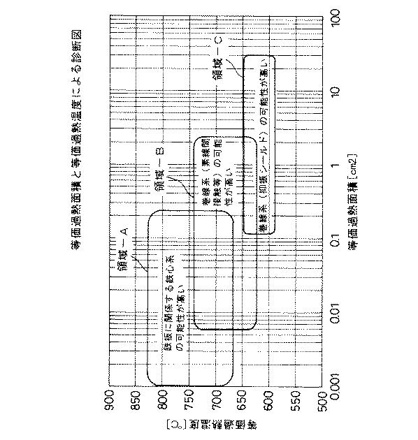
図4に鉄心系および巻線系のモデル実験により求めた、等価過熱温度と等価過熱面積の取り得る範囲を示す。
ここで○印で示す鉄心系は、鉄心の材料であるけい素鋼板に関する局部過熱について実験を行ったものであり、■印で示す巻線系一1は、変圧器巻線の並列導体間の接触による過熱、および◆印で示す巻線系ー1は主回路リード線の緩みによる過熱の実験、×印で示す巻線系一2は厚い絶縁氏に包まれた細いリード線(抑振シールドリード線)の過熱について実験を行ったものである。
【0035】
実験結果によると鉄心系の異常によるガス発生では、等価過熱温度が高く等価過熱面積が小さい範囲に分布しており、実験モデルの過熱による等価過熱温度と等価過熱面積は図4の領域一Aに分布している。巻線系一1の過熱によるガス発生では図4の領域一Bに分布しており、鉄心系に比べ等価過熱温度が低く等価過熱面積が低い範囲になっており、鉄心系と巻線系とで有意差が認められる。巻線系一2の場合には図4の領域一Cに分布しており、巻線系一1の場合よりさらに等価過熱温度が低く、等価過熱面積が広くなっている。
【0036】
また、過去に油中ガス分析による診断で異常が認められ、内部点検や解体調査により異常箇所が明らかになった変圧器について、等価過熱温度と等価過熱面積の関係をプロットした結果を図5に示す。
図5において領域一A〜領域一Cは、モデル実験で得られた領域を示す。
過去の事例では、図5に見られるようにサンプル数は少ないが、鉄心系と巻線系でモデル実験のときと同様な有意差が認められる。
【0037】
このように、鉄心系と巻線系で等価過熱面積と等価過熱温度の関係に有意差が認められるのは、鉄心系の異常の場合には、薄いけい素鋼板の局部で過熱するため、面積が小さく鉄板への熱伝導も悪いため過熱温度が高く過熱面積が小さくなる傾向にあり、一方巻線系の異常の場合には、熱伝導がよい銅線を絶縁紙で包んでいる構造のため、過熱面積が広く過熱温度が低い傾向にあると考えられる。
【0038】
以上の結果を基に、図6で示す等価過熱温度と等価過熱面積による本発明の診断図を作成し、油中ガス分析により異常の認められた変圧器について、等価過熱温度と等価過熱面積を計算して診断図にプロットすることにより、異常箇所が鉄心系か巻線系かを判別する方法を実用化できる。
【0039】
【実施形態2】
ガス比率(エチレン/メタン比)と過熱面積係数による診断
等価過熱温度と等価過熱面積による診断図の等価過熱温度は、(1)式で示されるようにエチレン/メタン比(C2H4/C2H6比)から計算しており、診断図として直接C2H4/C2H6比を用いても同じように鉄心系と巻線系の判別を行うことができる。この方法による実施形態を図7に示す。
【0040】
【実施形態3】
ガス発生のトレンドおよび等価過熱面積による診断
等価過熱面積と等価過熱温度による診断により、鉄心系と巻線系の判別精度を向上することができるが、鉄心系と巻線系で領域が重なっている部分があり、また鉄心系でも二重接地の場合には広い範囲に分布することが考えられる。そこでガス発生のトレンドと等価過熱面積の閾値の組み合わせによる診断方法を用いることにより、さらに鉄心系と巻線系の判別精度を向上することができる。
ガス発生トレンドの例を図8〜図12に示す。
ここで図8〜図10はモデル実験で得られたデータであり、図11,12は実器のデータ例を示す。図の点線は可燃性ガス総量(TCG濃度)の変化を示し、実線は月当たりの可燃性ガス総量の増加率を示す。
【0041】
モデル実験結果では、巻線系においては図8のように可燃性ガス総量の増加率が徐々に拡大する傾向が認められ、一方、鉄心系では図9,図10に示すようにある時点で油中分解ガスが急増したり、停止したりする現象が認められた。
また、過去にガス分析で異常があり、内部点検や解体調査により異常箇所が明らかになった変圧器についても、巻線系では、図11に示すように可燃性ガス総量の増加率が徐々に増加していき、鉄心系では、図12に示すようにガス発生が急増して停止するなどモデル実験と同様な傾向が認められた。
【0042】
鉄心系と巻線系でガス発生のトレンドに違いがあるのは以下のように説明できる。
巻線系の異常は巻線の並列素線間の接触による異常やリード線接続部の接触不良によるものであり、巻線には電圧が印加され負荷電流が流れているので異常箇所が過熱し、絶縁紙の黒化や銅線の溶損により異常が進展してガス発生量が徐々に大きくなる傾向が強い。
一方、鉄心系の異常では直接電圧の印加や電流が流れる箇所でなく、絶縁されていた箇所が接触して循環電流が流れて過熱するなど急激なガス発生になる傾向が強く、また鉄心の材料であるけい素鋼板は板厚が薄く異常箇所が溶損すると循環電流の経路が無くなり、ガス発生が停止する傾向がある。
【0043】
これらの事実から、可燃性ガス総量のトレンドまたは可燃性ガス総量の増加率から、ガス発生のトレンドを、
a.増加率がほぼ一定
b.ガス急増後に停止
c.ある時点から急増
d.増加率が徐々に上昇
のパターンに分類することにより、鉄心系と巻線系の判別に使用できる。
このうち、dの増加率が徐々に拡大する場合が巻線系である可能性が高いが、より精度を高めるため上記した「診断の実施形態1」の方法により算出した等価過熱面積係数の閾値を越えた場合に、巻線系であると判定する。
また、鉄心系についてはガス発生のトレンドがa〜cの場合となるが、過熱面積係数の閾値以下であれば鉄板に関係する鉄心系の可能性が高いと判断する。
過熱面積係数の閾値はデータの蓄積により決定するが、例えばモデル実験において得られた鉄板に関係する鉄心系の等価過熱面積の最大値O.2cm2を用いることができる。
【0044】
表1に本発明のガス発生トレンドと過熱面積係数を組み合わせた診断表の例を示す。
【0045】
【表1】
【実施形態4】
診断ソフトヘの組み込み
上記した診断方法を、油中ガス分析データを蓄積して油入変圧器の診断を行うソフトウエアを図1〜3の分析装置2又は監視制御システム5に組み込み、等価過熱温度と等価過熱面積またはエチレン/エタン比と等価過熱面積による診断図やガス発生トレンドと等価過熱面積による診断表を用いて異常箇所の診断を行うことができる。
【0047】
図13で示す従来の電気協同研究会の様相診断による診断に、本発明による異常箇所の判別方法を追加して診断を行うことで、油入変圧器の保守管理を精度よく行うことができる。
【0048】
【発明の効果】
(1)以上のとおり、従来では主として油中ガス分析結果の絶対値による診断であったものを、本発明においては、以前の採油データと比較したガス増加率やその変化を用い、異常箇所の過熱温度や過熱面積を推定して実験や過去の事例と比較することや、ガス発生の変化(トレンド)に注目して診断する方法であり、異常箇所の様相診断として異常箇所の判別精度を向上させることができる。
(2)等価過熱温度等価過熱面積による診断は、グラフ上に油中ガス分析結果から計算した指標をプロットする方法であり、油中ガス分析データから異常箇所の様相(過熱温度、過熱面積)を推定できるとともに、診断結果を図示できるので目視により容易に異常の様相を判断することができる。
(3)油中ガス分析結果のトレンドをパターン化して等価過熱面積の閾値と組み合わせた診断表を用いることにより、異常箇所の原因(鉄板に関係する鉄心の異常、二重接地による異常、巻線系の異常)を判別することができる。
(4)本発明の診断方法は、油入変圧器の診断ソフト監視装置などに組み込み易く、従来の方法とともに診断ソフトに組み込んで運用することにより、油中ガス分析による保守管理の適正化を図ることができる。
(5)異常箇所の判別の精度が向上することにより、巻線系の異常の場合には早い段階での改修を行うことにより、事故の未然防止を図ることができる。
(6)油中ガス分析により異常を検出した後の油分析の追跡インターバルを、異常箇所の状況に応じた適切な間隔(電気的事故に結びつく可能性の高い巻線系の追跡インターバルを短く、変圧器の停止に結びつかない鉄心系の追跡インターバルを長くする)にすることができ、保守費用の低減と保守管理レベルの適正化を図ることができる。
【図面の簡単な説明】
【図1】本発明の実施形態を示す構成図。
【図2】本発明の他の実施形態を示す構成図。
【図3】本発明の他の実施形態を示す構成図。
【図4】モデル実験における等価過熱面積と等価過熱温度の関係図。
【図5】過去の事例における等価過熱面積と等価過熱温度の関係図。
【図6】等価過熱面積と等価過熱温度による診断図。
【図7】エチレン/メタン比と過熱面積係数による診断図。
【図8】巻線系の増加率拡大の例図。
【図9】鉄心系の増加率急増後停止の例図。
【図10】鉄心系の増加率一定の例図。
【図11】実器による巻線系の増加率拡大図の例図。
【図12】実器による鉄心系の急増後の停止の例図。
【図13】油中ガス分析による診断フロー図。
【図14】鉄心系のガスパターン例図。
【図15】巻線系のガスパターン例図。
【図16】巻線系のガスパターン例図。
【図17】異常診断図による診断例図。
【図18】過熱温度とガス成分図。
【図19】過熱温度とガス生成量の関係図。
【符号の説明】
1…変圧器
2…分析装置
3…表示部
4…油中ガスセンサー
5…監視制御システム
6…伝送装置[0001]
TECHNICAL FIELD OF THE INVENTION
The present invention relates to a diagnostic method for determining whether there is an abnormality in a transformer by analyzing gas in oil of an oil-immersed transformer.
[0002]
[Prior art]
As part of the maintenance management technology for oil-immersed transformers, there is a method of applying gas-in-oil analysis to diagnose the presence or absence of abnormalities in the transformer.This method can be easily performed while the transformer is operating. It has been put into practical use and applied to transformers in operation to help prevent accidents.
[0003]
The maintenance management method based on gas-in-oil analysis is that if there is an abnormality inside the transformer and discharge or overheating has occurred, the insulating oil is decomposed to generate cracked gas. Then, an abnormality is diagnosed by analyzing a gas component contained in the insulating oil.
At that time, the maintenance management standards based on gas-in-oil analysis are summarized in the Electric Cooperative Research Society Vol. 54, No. 5 (Part 1) Maintenance Management of Oil-immersed Transformers. It is operated based on.
[0004]
As gas components, nitrogen (N 2 ), oxygen (O 2 ), hydrogen (H 2 ), methane (CH 4 ), ethane (C 2 H 6 ), ethylene (C 2 H 4 ), acetylene (C 2 H 2) ), Carbon monoxide (CO), and carbon dioxide (CO 2 ) are used, and the amount of each gas component is analyzed and used for diagnosis.
Of the above gases, the sum of H 2 , CH 4 , C 2 H 6 , C 2 H 4 , C 2 H 2 , and CO is referred to as the total combustible gas (TCG), and is used to measure discharge or overheating. It is used as a management index as the amount of gas generated by the decomposition of oil due to abnormalities.
[0005]
According to the maintenance management standard (Non-Patent Document 1) of the Electric Cooperative Research Association, the transformer status is normal, caution required 1, caution required 2, abnormal level based on the absolute amount / increase amount of specific gas from the results of gas analysis in oil. And is managed by the diagnosis flow of FIG.
As shown in FIG. 13, the following modality diagnosis method is defined to determine the location of the abnormality, the degree of the abnormality, and the urgency from the results of the gas-in-oil analysis.
(1), diagnosis by gas pattern (modality diagnosis 1)
(2) Diagnosis by composition ratio (abnormality diagnosis diagram) (modality diagnosis 2)
(3) Diagnosis by specific gas (modality diagnosis 3)
In the diagnostic method based on the gas pattern of (1), the horizontal axis indicates the target gas, and the vertical axis indicates the maximum value of each gas as 1 (the gas showing the maximum value is referred to as a leading gas), and plots the ratio thereof. Then, a pattern diagram is drawn, and the contents of the abnormality are diagnosed based on the shape of the pattern diagram. It is known that gas patterns differ between discharge and overheating due to abnormalities inside the transformer, and the appearance of abnormal parts is diagnosed based on the gas patterns.
[0006]
The diagnostic method based on the composition ratio of (2) is to judge the content of the abnormal phenomenon from the ratio of the gas amount of C 2 H 2 , C 2 H 4 and C 2 H 6 as the specific gas. It is summarized as a diagnostic diagram.
The abnormality diagnosis diagram plots the ratio of C 2 H 4 / C 2 H 6 on the horizontal axis and the ratio of C 2 H 2 / C 2 H 4 and C 2 H 2 / C 2 H 6 on the vertical axis. It is possible to distinguish between arc discharge and partial discharge among the discharges and the overheat.
[0007]
The diagnosis using the specific gas of (3) is a method of diagnosing by focusing on an extremely specific gas in diagnosing the content of the abnormality. CO, CO 2 , C 2 H 2, or the like is applied as a typical gas. For example, if the insulating paper is overheated, the rate of generation of carbon dioxide gas increases. Therefore, if CO 2 / CO ≦ 3, it is diagnosed that the insulating paper is overheated.
[0008]
[Non-patent document 1]
The Institute of Electric Cooperative Research "Electric Cooperative Research" Vol. 54 No. 5 (1)
Maintenance of oil-immersed transformer issued February 2000 [0009]
[Non-patent document 2]
"Behavior of Decomposed Gases due to Local Heating of Insulating Oil" Tsukioka et al. (Transactions of the Institute of Electrical Engineers of Japan, A98, No. 7, 1978)
[0010]
[Problems to be solved by the invention]
From the viewpoint of maintenance management of oil-immersed transformers, if an abnormality is detected by gas-in-oil analysis, it is important to determine where and how much abnormality will occur and, in particular, abnormalities in the iron core system (such as It is generated by the iron core and structural material that constitutes it, and the abnormal part is not connected to the main circuit and the electrical circuit, so it does not directly lead to the stop of the transformer) and the abnormality of the winding system (mainly the transformer It is related to the windings to be configured, and is a place where a voltage is constantly applied and a load current flows, and it is necessary to accurately determine an abnormality which leads to an electrical accident and immediately stops.
[0011]
However, the conventional method of determining an abnormal portion between the iron core system and the winding system is the diagnostic method of (1) to (3) described above, and the hydrogen (H 2 ) or acetylene (C 2 H 2 ) -driven gas pattern is used. If a specific gas such as CO or CO 2 is generated in the discharge area in the composition ratio (abnormality diagnosis diagram), the possibility of abnormality due to the discharge of the winding system can be determined. It is difficult to make an accurate decision.
[0012]
In the diagnosis method based on the gas pattern, the gas pattern due to the abnormality in the overheating mode is a gas pattern led by ethylene or methane in both the iron core system and the winding system as shown in FIGS. There have been cases where it was erroneously determined that the possibility of iron core overheating was high.
[0013]
In the abnormality diagnosis diagram, it is possible to determine whether the appearance of the abnormality is discharge or overheating.In the case of an abnormality in the overheating mode, it is possible to determine whether the overheating temperature is high or low or whether or not discharge is included. It is difficult to determine whether it is a wire type or an iron type. Even in an actual diagnosis example, as shown in FIG. 17, it is possible to determine a discharge having a large energy. However, in the overheating mode, there are many cases where an abnormality in the iron core system and an abnormality in the winding system are plotted in the same region, and it is difficult to determine.
The reason for this is that the molecules of the insulating oil are decomposed and gasified due to the generation of decomposed gas due to overheating, and the composition of the decomposed gas changes depending on the temperature of the superheated part. It is considered that the effect of the impact is small.
[0014]
In the diagnosis using the specific gas, CO and CO 2 are used as diagnostic indicators for overheating of the insulating paper of the windings. However, when the overheating is localized, the amount of generated CO and CO 2 is small, and the transformer is operated in normal operation. It is hidden by CO and CO 2 generated from the whole insulating paper, and it is difficult to discriminate between the winding system and the iron core system particularly in a large capacity device.
[0015]
In the Electric Cooperative Research Vol. 54, No. 5 (Part 1), the maintenance management of oil-immersed transformers (Non-patent Document 1) summarizes the principle of generation of cracked gas in oil theoretically, and It states that the superheat temperature and the superheat area can be estimated.
Regarding the superheat temperature, the composition of the gas generated by the overheating of the insulating oil changes as the temperature changes, and the higher the temperature, the higher the proportion of unsaturated hydrocarbons. Therefore, as shown in FIG. The thermal decomposition temperature can be estimated from the ratio of the unsaturated hydrocarbon.
Also, the gas generation rate increases as the temperature increases, and there is a linear relationship between the superheat temperature and the gas generation rate per unit area as shown in FIG. It is described that a superheat temperature can be estimated from a composition ratio and a superheat area can be estimated from a production rate.
[0016]
However, in the Electric Cooperative Research Vol. 54, No. 5 (Part 1), the maintenance of the oil-immersed transformer does not consider the relationship between the superheat temperature and the superheat area and the abnormal location. It is difficult to determine whether the winding system is used.
[0017]
Therefore, an object of the present invention is to provide a diagnostic method capable of accurately estimating an abnormal portion of a transformer.
[0018]
[Means for Solving the Problems]
A first aspect of the present invention provides a method of diagnosing the presence or absence of an abnormality in a transformer using oil-in-oil gas analysis data obtained by sampling oil from an oil-immersed transformer,
Estimate the equivalent superheat temperature from the ratio of ethylene and ethane in the analysis gas components, estimate the amount of gas generated per unit area per unit time from the superheat temperature, and calculate the flammable oil in oil calculated from the oil-in-oil gas analysis data for each oil sample. Calculate the equivalent superheated area (coefficient of superheated area) from the rate of increase in the total amount of reactive gas per unit time and the amount of gas generated per unit time per unit area, and graph the relationship between the equivalent superheated area and the equivalent superheated temperature. It is characterized by diagnosing an abnormal part by a diagnosis diagram comparing with a possible range of the iron core system and the winding system.
[0019]
A second aspect of the present invention is to graph the relationship between the calculated equivalent superheated area (coefficient of superheated area) and the ratio of ethylene and ethane, and to diagnose abnormal spots by a diagnostic diagram comparing with the possible ranges of the iron core system and the winding system. It is characterized by making a diagnosis.
[0020]
A third aspect of the present invention is to classify a gas generation trend into a pattern from the trend of the total combustible gas or the increase rate of the total combustible gas using the oil-in-oil gas analysis data analyzed and analyzed, and It is characterized in that abnormal points are diagnosed using a diagnosis table based on classification of the area (overheated area coefficient) with a threshold value.
[0021]
A fourth feature of the present invention is characterized in that the trend pattern is a pattern classification in which the rate of increase is substantially constant, stops after a sudden increase in gas, and suddenly increases from a certain point in time and the rate of increase gradually increases.
[0022]
A fifth aspect of the present invention is characterized in that the diagnosis of the presence or absence of abnormality of the transformer by the gas-in-oil analysis is incorporated into software, and the diagnosis is performed by displaying or outputting a diagnosis result in a diagnosis diagram or a diagnosis table. is there.
[0023]
According to a sixth aspect of the present invention, the diagnosis of the presence or absence of an abnormality in the transformer by the oil-in-gas analysis is obtained by any of a device-installed monitoring control system, a monitoring control system using a communication line, and a portable analyzer. The diagnosis is performed using the gas-in-oil analysis data or the gas-in-oil analysis data to which the analysis result is input.
[0024]
BEST MODE FOR CARRYING OUT THE INVENTION
FIG. 1 shows an embodiment in which the diagnostic method of the present invention is applied to a portable analyzer. A sample taken from a
[0025]
FIG. 2 shows an embodiment applied to a device-installed monitoring device.
[0026]
FIG. 3 shows an embodiment in which data detected by the gas-in-
[0027]
Diagnosis method based on equivalent superheated area and equivalent superheated temperature Electric Cooperative Research Vol. 54, No. 5 (Part 1) In the maintenance management of oil-immersed transformers, as described above, the superheated temperature and the superheated area at the abnormal location are determined by the data in the past literature. The superheat temperature and the superheat area are estimated from the gas analysis data of the target unit based on the gas analysis data of the transformer whose abnormal point is known through model experiments and internal inspections. From the relationship, it is determined whether the abnormal part is an iron core type or a winding type. The method for the determination will be described below.
[0028]
Estimation of Equivalent Superheat Temperature The superheat temperature is estimated using the ratio of ethylene (unsaturated hydrocarbon) and ethane (saturated hydrocarbon) gas, and is calculated from equation (1) using experimental data in the literature.
[0029]
T = 320 × 1 og (C 2 H 4 / C 2 H 6 ) 530 (1)
Source: "The behavior of cracked gas due to local overheating of insulating oil" by Tsukioka et al. (Transactions of the Institute of Electrical Engineers of Japan, A98, No. 7, 1978), (Non-Patent Document 2) Difference between the shape of the experimental model and the abnormal part of the actual device Therefore, the superheat temperature of the actual device is not always the same as the expression (1), and the superheat temperature obtained by the expression (1) is referred to as an equivalent superheat temperature in the present invention.
[0030]
Estimation of equivalent superheated area The equivalent superheated area is calculated from the relationship between the increase rate of the total combustible gas amount, the oil amount of the transformer, the superheat temperature, and the gas generation rate per unit time per unit area. The rate of increase in the total amount of combustible gas can be calculated by the equation (2) from the difference between the data of the gas-in-oil analysis and the previous value.
[0031]
C = △ TCG / △ D × 30 (2)
Here, C: TCG increase rate (ppm / month), △ TCG: difference in TGC gas amount (ppm), △ D: oil analysis data interval (days)
The superheat area S can be calculated by the following equation.
[0032]
S = (Qoil × C × 10 −3 ) / (30 × 24 × K) (3)
Here, Qoil: transformer oil amount (Lit), C: flammable gas generation amount (ppm / month), K: gas generation rate per unit area per unit time (ml / cm 2 / h)
The following formula is used to calculate the gas generation rate K per unit area per unit time using the data of
[0033]
Log (K) = 14-12000 / (T + 273) T> 562
Log (K) = 5.5-4900 / (T + 273) 562>T> 285
Log (K) = 1.2-2500 / (T + 273) T <285 (4)
As in the case of the superheat temperature, the amount of gas generated per unit area per unit time of the actual device is not always the same as the equation (4). It is called the area or superheated area factor.
[0034]
Judgment by the equivalent superheated temperature and the equivalent superheated area Determination of whether the abnormal point is an iron core system or a winding system is performed by plotting the relationship between the equivalent superheated temperature and the equivalent superheated area calculated by the above formula from the oil-in-gas analysis data, It is compared with the range calculated from model experiments and past cases.
FIG. 4 shows the possible ranges of the equivalent superheated temperature and the equivalent superheated area obtained by the model tests of the iron core system and the winding system.
Here, the core system indicated by a circle is obtained by conducting an experiment on local overheating of a silicon steel plate as a material of the iron core, and the winding system 11 indicated by a triangle is formed between parallel conductors of a transformer winding. The overheating due to contact and the winding system -1 indicated by the symbol 実 験 are experiments of overheating due to the loosening of the main circuit lead wires, and the winding
[0035]
According to the experimental results, in the gas generation due to the abnormality of the iron core system, the equivalent superheat temperature is distributed in a range where the equivalent superheat area is high and the equivalent superheat area is small. Are distributed. In the gas generation due to overheating of the winding system 11, the gas is distributed in the region 1B in FIG. 4, and the equivalent superheating temperature is lower than that of the iron core system, and the equivalent heating area is lower. , A significant difference is observed. In the case of the winding
[0036]
Fig. 5 shows the results of plotting the relationship between equivalent superheated temperature and equivalent superheated area for transformers in which abnormalities were found in the past by gas-in-oil analysis and abnormalities were clarified by internal inspection and dismantling inspections. Show.
In FIG. 5, regions 1A to 1C indicate regions obtained by the model experiment.
In the past case, as shown in FIG. 5, the number of samples is small, but a significant difference similar to that in the model experiment is recognized between the iron core system and the winding system.
[0037]
As described above, a significant difference in the relationship between the equivalent superheated area and the equivalent superheated temperature in the iron core system and the winding system is recognized because, in the case of an abnormality in the iron core system, since the thin silicon steel plate is locally heated, the area is increased. The superheat temperature tends to be high and the superheated area tends to be small due to the small heat conduction to the iron plate.On the other hand, when the winding system is abnormal, the copper wire with good heat conduction is wrapped with insulating paper. It is considered that the overheating area is large and the overheating temperature tends to be low.
[0038]
Based on the above results, a diagnostic diagram of the present invention was prepared based on the equivalent superheat temperature and the equivalent superheat area shown in FIG. 6, and the equivalent superheat temperature and the equivalent superheat area were determined for the transformer in which abnormality was recognized by the oil-in-gas analysis. By calculating and plotting on a diagnostic diagram, a method of determining whether the abnormal part is an iron core system or a winding system can be put to practical use.
[0039]
The diagnostic superheat temperature based on the gas ratio (ethylene / methane ratio) and the superheat area coefficient and the equivalent superheat temperature in the diagnostic diagram based on the equivalent superheat area are represented by the ethylene / methane ratio (C 2 H 4 / C) as shown in equation (1). 2 H 6 ratio), and the core system and the winding system can be similarly determined by directly using the C 2 H 4 / C 2 H 6 ratio as a diagnostic diagram. An embodiment according to this method is shown in FIG.
[0040]
Diagnosis based on gas generation trend and equivalent superheated area Diagnosis based on equivalent superheated area and equivalent superheated temperature can improve the accuracy of discriminating between core system and winding system, but the area is overlapped between core system and winding system There is a part, and it is conceivable that the iron core system is distributed over a wide range in the case of double grounding. Therefore, by using a diagnostic method based on a combination of a gas generation trend and a threshold value of an equivalent superheated area, it is possible to further improve the discrimination accuracy between the iron core system and the winding system.
Examples of gas generation trends are shown in FIGS.
8 to 10 show data obtained by a model experiment, and FIGS. 11 and 12 show data examples of a real device. The dotted line in the figure indicates a change in the total amount of combustible gas (TCG concentration), and the solid line indicates the rate of increase in the total amount of combustible gas per month.
[0041]
According to the model experiment results, the increase rate of the total flammable gas in the winding system tends to gradually increase as shown in FIG. 8, while the oil system at a certain time as shown in FIGS. A phenomenon in which the middle decomposition gas rapidly increased or stopped was observed.
In addition, for transformers in which abnormalities were found in gas analysis in the past, and abnormalities were clarified by internal inspection and dismantling inspection, in the winding system, the rate of increase in the total amount of flammable gas gradually increased as shown in FIG. As shown in FIG. 12, the same tendency as in the model experiment was observed in the iron core system, such as a sudden increase in gas generation and a stop.
[0042]
The difference in the gas generation trend between the iron core system and the winding system can be explained as follows.
Abnormalities in the winding system are caused by contact between the parallel strands of the winding or by poor contact in the lead wire connection.Voltage is applied to the winding and the load current is flowing, so the abnormal location may overheat. In addition, there is a strong tendency that abnormalities develop due to blackening of the insulating paper and erosion of the copper wire, and the amount of generated gas gradually increases.
On the other hand, in the case of an abnormality in the iron core system, there is a strong tendency to generate sudden gas, such as overheating due to contact with the insulated part, not the place where direct voltage application or current flows, but also the material of the iron core. When the silicon steel sheet is thin, the thickness of the sheet is so thin that if the abnormal part is melted, the path of the circulating current is lost and the gas generation tends to stop.
[0043]
Based on these facts, the trend of gas generation can be calculated based on the trend of total combustible gas or the increase rate of total combustible gas,
a. The rate of increase is almost constant b. Stop after sudden increase of gas c. Rapid increase from a certain point d. By classifying the increase rate into a gradually increasing pattern, it can be used for discriminating between the iron core system and the winding system.
Of these, the case where the rate of increase of d gradually increases is likely to be the winding system, but the threshold value of the equivalent superheated area coefficient calculated by the method of “
In the case of the iron core system, the gas generation trend is a to c. When the trend is below the threshold value of the superheat area coefficient, it is determined that the possibility of the iron core system related to the iron plate is high.
The threshold value of the superheated area coefficient is determined by accumulating data. For example, the maximum value O.E. of the equivalent superheated area of the iron core system related to the iron plate obtained in the model experiment is determined. 2 cm 2 can be used.
[0044]
Table 1 shows an example of a diagnosis table in which the gas generation trend and the overheating area coefficient of the present invention are combined.
[0045]
[Table 1]
Incorporation of diagnostic software described above into the
[0047]
By performing the diagnosis by adding the method of determining an abnormal part according to the present invention to the diagnosis based on the conventional diagnosis by the electric cooperative society shown in FIG. 13, the maintenance management of the oil-immersed transformer can be performed accurately.
[0048]
【The invention's effect】
(1) As described above, what has been conventionally diagnosed mainly by the absolute value of the gas analysis result in oil, the present invention uses the gas increase rate and its change in comparison with the previous oil sampling data to determine the abnormal location. This method estimates the overheating temperature and area and compares it with experiments and past cases, and diagnoses by focusing on changes in gas generation (trend). Can be done.
(2) Equivalent superheat temperature Diagnosis by equivalent superheat area is a method of plotting an index calculated from the results of gas-in-oil analysis on a graph, and analyzing the appearance of abnormal points (superheat temperature, superheat area) from the gas-in-oil analysis data. Since it can be estimated and the diagnostic results can be illustrated, the appearance of the abnormality can be easily determined visually.
(3) By using a diagnosis table that patterns the trend of the results of gas analysis in oil and combines it with the threshold value of the equivalent superheated area, the cause of the abnormal location (abnormal iron core related to iron plate, abnormal grounding due to double grounding, winding System abnormality) can be determined.
(4) The diagnostic method of the present invention is easy to incorporate into a diagnostic software monitoring device for oil-immersed transformers, etc., and by incorporating it into diagnostic software along with the conventional method for operation, the maintenance management by gas-in-oil analysis is optimized. be able to.
(5) By improving the accuracy of the determination of an abnormal portion, in the case of an abnormality in the winding system, by performing repair at an early stage, it is possible to prevent an accident from occurring.
(6) The tracking interval of oil analysis after detecting an abnormality by gas-in-oil analysis should be set to an appropriate interval according to the situation of the abnormal location (the tracking interval of the winding system that is likely to lead to an electrical accident should be shortened. The tracking interval of the iron core system that does not lead to the stoppage of the transformer can be lengthened), so that the maintenance cost can be reduced and the maintenance management level can be optimized.
[Brief description of the drawings]
FIG. 1 is a configuration diagram showing an embodiment of the present invention.
FIG. 2 is a configuration diagram showing another embodiment of the present invention.
FIG. 3 is a configuration diagram showing another embodiment of the present invention.
FIG. 4 is a relationship diagram between an equivalent superheat area and an equivalent superheat temperature in a model experiment.
FIG. 5 is a diagram showing a relationship between an equivalent superheated area and an equivalent superheated temperature in a past case.
FIG. 6 is a diagnostic diagram based on an equivalent superheat area and an equivalent superheat temperature.
FIG. 7 is a diagnostic diagram based on an ethylene / methane ratio and a superheat area coefficient.
FIG. 8 is an example of an increase rate of an increase in a winding system.
FIG. 9 is a diagram showing an example of a stop after a sharp increase in the core system.
FIG. 10 is a diagram showing an example of a constant increase rate of the iron core system.
FIG. 11 is an example of an enlarged view of an increase rate of a winding system by an actual device.
FIG. 12 is a diagram showing an example of a stop after a sudden increase in the iron core system by an actual device.
FIG. 13 is a flowchart of diagnosis by gas-in-oil analysis.
FIG. 14 is a diagram showing an example of an iron core gas pattern.
FIG. 15 is an example diagram of a gas pattern of a winding system.
FIG. 16 is a diagram showing an example of a gas pattern of a winding system.
FIG. 17 is a diagram illustrating a diagnosis example based on an abnormality diagnosis diagram.
FIG. 18 is a diagram showing superheat temperature and gas components.
FIG. 19 is a graph showing a relationship between a superheat temperature and a gas generation amount.
[Explanation of symbols]
DESCRIPTION OF
Claims (6)
前記分析ガス成分のうちエチレンとエタンの比率から等価過熱温度を推定し、過熱温度から単位面積単位時間あたりのガス生成量を推定し、各採油毎の油中ガス分析データから算出した油中可燃性ガス総量の単位時間当たりの増加率と単位時間単位面積あたりのガス生成量から等価過熱面積(過熱面積係数)を計算して、等価過熱面積と等価過熱温度の関係をグラフ化し、変圧器の鉄心系および巻線系の取り得る範囲と比較した診断図によりて異常箇所を診断することを特徴とした油中ガス分析による油入変圧器の診断方法。Diagnosis of abnormalities in transformers using oil-in-oil transformers and oil gas analysis data analyzed
Estimate the equivalent superheat temperature from the ratio of ethylene and ethane in the analysis gas components, estimate the amount of gas generated per unit area per unit time from the superheat temperature, and calculate the flammable oil in oil calculated from the oil-in-oil gas analysis data for each oil sample. Calculate the equivalent superheated area (coefficient of superheated area) from the rate of increase in the total amount of reactive gas per unit time and the amount of gas generated per unit time per unit area, and graph the relationship between the equivalent superheated area and the equivalent superheated temperature. A method for diagnosing an oil-immersed transformer by gas-in-oil analysis, characterized by diagnosing an abnormal part based on a diagnosis diagram which is compared with a possible range of an iron core system and a winding system.
Priority Applications (1)
| Application Number | Priority Date | Filing Date | Title |
|---|---|---|---|
| JP2002366172A JP4315675B2 (en) | 2002-12-18 | 2002-12-18 | Diagnosis method of oil-filled transformer by gas analysis in oil |
Applications Claiming Priority (1)
| Application Number | Priority Date | Filing Date | Title |
|---|---|---|---|
| JP2002366172A JP4315675B2 (en) | 2002-12-18 | 2002-12-18 | Diagnosis method of oil-filled transformer by gas analysis in oil |
Publications (2)
| Publication Number | Publication Date |
|---|---|
| JP2004200348A true JP2004200348A (en) | 2004-07-15 |
| JP4315675B2 JP4315675B2 (en) | 2009-08-19 |
Family
ID=32763455
Family Applications (1)
| Application Number | Title | Priority Date | Filing Date |
|---|---|---|---|
| JP2002366172A Expired - Lifetime JP4315675B2 (en) | 2002-12-18 | 2002-12-18 | Diagnosis method of oil-filled transformer by gas analysis in oil |
Country Status (1)
| Country | Link |
|---|---|
| JP (1) | JP4315675B2 (en) |
Cited By (14)
| Publication number | Priority date | Publication date | Assignee | Title |
|---|---|---|---|---|
| JP2007317836A (en) * | 2006-05-25 | 2007-12-06 | Tokyo Electric Power Co Inc:The | Diagnosis method of oil-filled transformer |
| CN102033170A (en) * | 2009-09-29 | 2011-04-27 | 华东电力试验研究院有限公司 | Online measuring device of charge density of oil electrification in transformer |
| CN102662113A (en) * | 2012-04-17 | 2012-09-12 | 国网电力科学研究院 | Comprehensive diagnosis method of oil-immersed transformer based on fault tree |
| JP2015050869A (en) * | 2013-09-03 | 2015-03-16 | 株式会社かんでんエンジニアリング | Abnormality diagnosis system, decision tree generation system, decision tree generation method, and decision tree generation program of oil-filled electrical equipment |
| JP6045766B1 (en) * | 2016-06-15 | 2016-12-14 | 三菱電機株式会社 | Method for estimating overheat temperature of oil-filled electrical equipment |
| KR101711296B1 (en) * | 2015-09-02 | 2017-02-28 | 엘에스산전 주식회사 | System for dissolved gas analysis of transformer |
| KR101735282B1 (en) * | 2011-06-29 | 2017-05-16 | 현대중공업 주식회사 | Method for dissolved gas analysis of transformer |
| US10302618B2 (en) | 2014-08-27 | 2019-05-28 | Mitsubishi Electric Corporation | Method for diagnosing oil-filled electrical apparatus |
| US10359411B2 (en) | 2015-07-17 | 2019-07-23 | Mitsubishi Electric Corporation | Diagnosis method for internal fault of oil-immersed electric apparatus |
| CN112269151A (en) * | 2020-10-15 | 2021-01-26 | 芜湖金牛电气股份有限公司 | Method for diagnosing gas fault in transformer oil |
| CN112557991A (en) * | 2020-11-12 | 2021-03-26 | 珠海一多监测科技有限公司 | Current transformer fault diagnosis method based on mole number and temperature |
| US11015987B2 (en) | 2016-06-07 | 2021-05-25 | Mitsubishi Electric Corporation | Temperature estimation method |
| CN113504423A (en) * | 2021-07-13 | 2021-10-15 | 许昌许继软件技术有限公司 | Primary equipment online monitoring data trend prediction method and device |
| WO2022004139A1 (en) * | 2020-07-01 | 2022-01-06 | 株式会社日立製作所 | Transformer diagnosis method and diagnosis system |
-
2002
- 2002-12-18 JP JP2002366172A patent/JP4315675B2/en not_active Expired - Lifetime
Cited By (18)
| Publication number | Priority date | Publication date | Assignee | Title |
|---|---|---|---|---|
| JP2007317836A (en) * | 2006-05-25 | 2007-12-06 | Tokyo Electric Power Co Inc:The | Diagnosis method of oil-filled transformer |
| CN102033170A (en) * | 2009-09-29 | 2011-04-27 | 华东电力试验研究院有限公司 | Online measuring device of charge density of oil electrification in transformer |
| CN102033170B (en) * | 2009-09-29 | 2015-05-06 | 华东电力试验研究院有限公司 | Online measuring device of charge density of oil electrification in transformer |
| KR101735282B1 (en) * | 2011-06-29 | 2017-05-16 | 현대중공업 주식회사 | Method for dissolved gas analysis of transformer |
| CN102662113A (en) * | 2012-04-17 | 2012-09-12 | 国网电力科学研究院 | Comprehensive diagnosis method of oil-immersed transformer based on fault tree |
| JP2015050869A (en) * | 2013-09-03 | 2015-03-16 | 株式会社かんでんエンジニアリング | Abnormality diagnosis system, decision tree generation system, decision tree generation method, and decision tree generation program of oil-filled electrical equipment |
| US10302618B2 (en) | 2014-08-27 | 2019-05-28 | Mitsubishi Electric Corporation | Method for diagnosing oil-filled electrical apparatus |
| US10359411B2 (en) | 2015-07-17 | 2019-07-23 | Mitsubishi Electric Corporation | Diagnosis method for internal fault of oil-immersed electric apparatus |
| KR101711296B1 (en) * | 2015-09-02 | 2017-02-28 | 엘에스산전 주식회사 | System for dissolved gas analysis of transformer |
| US11015987B2 (en) | 2016-06-07 | 2021-05-25 | Mitsubishi Electric Corporation | Temperature estimation method |
| WO2017216890A1 (en) * | 2016-06-15 | 2017-12-21 | 三菱電機株式会社 | Method for estimating overheated temperature of oil-filled electric device |
| JP6045766B1 (en) * | 2016-06-15 | 2016-12-14 | 三菱電機株式会社 | Method for estimating overheat temperature of oil-filled electrical equipment |
| WO2022004139A1 (en) * | 2020-07-01 | 2022-01-06 | 株式会社日立製作所 | Transformer diagnosis method and diagnosis system |
| JP7405707B2 (en) | 2020-07-01 | 2023-12-26 | 株式会社日立製作所 | Transformer diagnostic method and system |
| CN112269151A (en) * | 2020-10-15 | 2021-01-26 | 芜湖金牛电气股份有限公司 | Method for diagnosing gas fault in transformer oil |
| CN112557991A (en) * | 2020-11-12 | 2021-03-26 | 珠海一多监测科技有限公司 | Current transformer fault diagnosis method based on mole number and temperature |
| CN112557991B (en) * | 2020-11-12 | 2024-05-28 | 珠海一多监测科技有限公司 | Current transformer fault diagnosis method based on mole number and temperature |
| CN113504423A (en) * | 2021-07-13 | 2021-10-15 | 许昌许继软件技术有限公司 | Primary equipment online monitoring data trend prediction method and device |
Also Published As
| Publication number | Publication date |
|---|---|
| JP4315675B2 (en) | 2009-08-19 |
Similar Documents
| Publication | Publication Date | Title |
|---|---|---|
| Sun et al. | A review of dissolved gas analysis in power transformers | |
| JP2004200348A (en) | Diagnostic method of oil filled transformer by analysis of gas-in-oil | |
| Gouda et al. | Condition assessment of power transformers based on dissolved gas analysis | |
| CN112598298A (en) | Power transformer health management system and management method | |
| CN104091416A (en) | Alarm system monitoring abnormal conditions of power transformer | |
| Gouda et al. | Power transformer incipient faults diagnosis based on dissolved gas analysis | |
| CN104090080A (en) | Monitoring method for abnormal state of oil-immersed transformer | |
| Gockenbach et al. | Condition monitoring and diagnosis of power transformers | |
| KR101046752B1 (en) | Transformer life assessment method | |
| JP2007317836A (en) | Diagnosis method of oil-filled transformer | |
| KR101290295B1 (en) | Fault diagnosis method of oil filled transformer using proportion ratio combination of dissolved gases | |
| JP4623334B1 (en) | Method for predicting the possibility of abnormality in oil-filled electrical equipment | |
| Al Hamdani et al. | Power transformer degradation condition and insulation index estimation based on historical oil dat | |
| Hamrick | Dissolved gas analysis for transformers | |
| JP5179587B2 (en) | Diagnostic method for oil-filled electrical equipment, diagnostic device for implementing the diagnostic method, and oil-filled electrical equipment equipped with the diagnostic device | |
| RU82867U1 (en) | DIAGNOSTIC SYSTEM FOR OIL-FILLED MEASURING TRANSFORMERS | |
| Dhote et al. | Fuzzy algorithm for power transformer diagnostics | |
| KR101290806B1 (en) | Fault diagnosis method of oil filled transformer using proportion ratio of dissolved gases | |
| Hosseini et al. | Construction of a transformer DGA health index based on DGA screening processes | |
| Okubo et al. | Electrical insulation diagnostic method and maintenance criteria for oil-immersed power transformers | |
| Gouda et al. | Power transformer incipient faults diagnosis based on dissolved gas analysis | |
| KR20220011046A (en) | Method for status prediction of transformer based on oil filtering and apparatus for using the method | |
| JP5233021B2 (en) | Method for estimating the amount of copper sulfide produced in oil-filled electrical equipment, method for diagnosing abnormality, method for estimating initial concentration of dibenzyl disulfide in insulating oil, and method for diagnosing the possibility of occurrence of abnormality | |
| Lybeck et al. | Online monitoring technical basis and analysis framework for large power transformers; Interim report for FY 2012 | |
| Lin et al. | A Pragmatic Approach to Diagnose on Transformer's Insulating Oil with Gas Pattern |
Legal Events
| Date | Code | Title | Description |
|---|---|---|---|
| A621 | Written request for application examination |
Free format text: JAPANESE INTERMEDIATE CODE: A621 Effective date: 20051012 |
|
| A131 | Notification of reasons for refusal |
Free format text: JAPANESE INTERMEDIATE CODE: A131 Effective date: 20080708 |
|
| A521 | Request for written amendment filed |
Free format text: JAPANESE INTERMEDIATE CODE: A523 Effective date: 20080905 |
|
| TRDD | Decision of grant or rejection written | ||
| A01 | Written decision to grant a patent or to grant a registration (utility model) |
Free format text: JAPANESE INTERMEDIATE CODE: A01 Effective date: 20090512 |
|
| A01 | Written decision to grant a patent or to grant a registration (utility model) |
Free format text: JAPANESE INTERMEDIATE CODE: A01 |
|
| A61 | First payment of annual fees (during grant procedure) |
Free format text: JAPANESE INTERMEDIATE CODE: A61 Effective date: 20090519 |
|
| R150 | Certificate of patent or registration of utility model |
Ref document number: 4315675 Country of ref document: JP Free format text: JAPANESE INTERMEDIATE CODE: R150 Free format text: JAPANESE INTERMEDIATE CODE: R150 |
|
| FPAY | Renewal fee payment (event date is renewal date of database) |
Free format text: PAYMENT UNTIL: 20120529 Year of fee payment: 3 |
|
| FPAY | Renewal fee payment (event date is renewal date of database) |
Free format text: PAYMENT UNTIL: 20120529 Year of fee payment: 3 |
|
| FPAY | Renewal fee payment (event date is renewal date of database) |
Free format text: PAYMENT UNTIL: 20130529 Year of fee payment: 4 |
|
| R250 | Receipt of annual fees |
Free format text: JAPANESE INTERMEDIATE CODE: R250 |
|
| FPAY | Renewal fee payment (event date is renewal date of database) |
Free format text: PAYMENT UNTIL: 20140529 Year of fee payment: 5 |
|
| R250 | Receipt of annual fees |
Free format text: JAPANESE INTERMEDIATE CODE: R250 |
|
| S533 | Written request for registration of change of name |
Free format text: JAPANESE INTERMEDIATE CODE: R313533 |
|
| R350 | Written notification of registration of transfer |
Free format text: JAPANESE INTERMEDIATE CODE: R350 |
|
| R250 | Receipt of annual fees |
Free format text: JAPANESE INTERMEDIATE CODE: R250 |
|
| EXPY | Cancellation because of completion of term |