JP2004197660A - Internal combustion engine and its combustion method - Google Patents
Internal combustion engine and its combustion method Download PDFInfo
- Publication number
- JP2004197660A JP2004197660A JP2002367579A JP2002367579A JP2004197660A JP 2004197660 A JP2004197660 A JP 2004197660A JP 2002367579 A JP2002367579 A JP 2002367579A JP 2002367579 A JP2002367579 A JP 2002367579A JP 2004197660 A JP2004197660 A JP 2004197660A
- Authority
- JP
- Japan
- Prior art keywords
- fuel
- combustion chamber
- engine
- low
- injection valve
- Prior art date
- Legal status (The legal status is an assumption and is not a legal conclusion. Google has not performed a legal analysis and makes no representation as to the accuracy of the status listed.)
- Granted
Links
Images


Classifications
-
- Y—GENERAL TAGGING OF NEW TECHNOLOGICAL DEVELOPMENTS; GENERAL TAGGING OF CROSS-SECTIONAL TECHNOLOGIES SPANNING OVER SEVERAL SECTIONS OF THE IPC; TECHNICAL SUBJECTS COVERED BY FORMER USPC CROSS-REFERENCE ART COLLECTIONS [XRACs] AND DIGESTS
- Y02—TECHNOLOGIES OR APPLICATIONS FOR MITIGATION OR ADAPTATION AGAINST CLIMATE CHANGE
- Y02T—CLIMATE CHANGE MITIGATION TECHNOLOGIES RELATED TO TRANSPORTATION
- Y02T10/00—Road transport of goods or passengers
- Y02T10/10—Internal combustion engine [ICE] based vehicles
- Y02T10/12—Improving ICE efficiencies
Abstract
Description
【0001】
【発明の属する技術分野】
この発明は、オクタン価の異なる複数種類の燃料を燃焼室に供給して機関燃焼を行う内燃機関に関する。
【0002】
【従来の技術】
一般にガソリン内燃機関では、燃焼室内に供給される燃料及び空気の混合気に点火プラグを用いて点火し、燃焼させることによってエンジン出力を発生させる。
【0003】
【特許文献1】
特開2000−179368号公報
【0004】
【発明が解決しようとする課題】
ところで、例えば円筒形燃焼室の天井の中央部に点火プラグを設け、混合気の点火を行う場合、点火プラグを起点とし、燃焼室の周縁部に向かって火炎が伝播する。このとき、燃焼室の周縁部に存在する未燃の混合気(末端ガス)が点火プラグから拡がる火炎(圧力波)によって圧縮され、点火プラグを起点として伝播する火炎が燃焼室の周縁部に到達する前に自己点火する。この末端ガスの自己点火はノッキングと呼ばれ、異音の発生や、エンジンの耐久性低下等といった問題を生じさせる。
【0005】
本発明は、こうした実情に鑑みてなされたものであり、その目的とするところは、ノッキングを効果的に防止することのできる内燃機関を提供することにある。
【0006】
【課題を解決するための手段】
上記目的を達成するため、本発明は、(1)内燃機関の燃焼室内に高オクタン価燃料を供給する第1の燃料供給手段と、前記燃焼室内に低オクタン価燃料を直接噴射供給し、同燃料室内の複数箇所に低オクタン価燃料の噴霧を点在させる第2の燃料供給手段と、前記第1の燃料供給手段を通じて前記燃焼室内に高オクタン価燃料の雰囲気を形成した後、前記第2の燃料供給手段を通じて前記燃焼室内の複数箇所に低オクタン価燃料の噴霧を点在させる制御手段と、を備えることを要旨とする。
【0007】
同構成によれば、燃焼室内において、高オクタン価燃料による高温の雰囲気を形成し、その雰囲気中に低オクタン価燃料の噴霧の塊を点在させて自然発火を促すことで、機関燃焼を行うことになる。すなわち、爆発行程(膨張行程)において、燃焼室内の複数個所を起点として火炎が拡がるため、実質的な燃焼速度が上がり、ノッキングが発生する前に燃焼を完了することができる。
(2)前記制御手段は、前記第2の燃料供給手段を通じた前記燃焼室内への低オクタン価燃料の供給を、当該機関の吸気行程および圧縮行程に行うようにしてもよい。
【0008】
同構成によれば、例えばエンジン負荷が低く、燃料の着火遅れが生じやすい条件下で、圧縮行程の後期に噴射供給される低オクタン価燃料の着火遅れを効果的に防止することができる。
(3)前記制御手段は、前記第2の燃料供給手段を通じた前記燃焼室内への低オクタン価燃料の供給を、前記圧縮行程において少なくとも2回行うようにしてもよい。
【0009】
同構成によれば、低オクタン価燃料の噴射供給を複数回連続して行うことで、第2の燃料供給手段の構造の複雑化や設置数の増大を伴うことなく、燃焼室内に形成される低オクタン価燃料の噴霧の塊の数を調整することができる。
(4)また、前記制御手段は、前記第2の燃料供給手段を通じた前記燃焼室内への低オクタン価燃料の供給を、前記圧縮行程及び膨張行程に行うようにしてもよい。
【0010】
同構成によれば、第2の燃料供給手段を通じて形成された燃料噴霧の塊を起点として、燃料の爆発に伴い火炎(圧力波)が燃焼室の周縁部に向かって伝播する過程で、燃焼室の周縁部近傍に存在する未燃の高オクタン価燃料に向かって低オクタン価燃料の噴霧が供給されることになる。これにより、燃焼室の周縁部近傍に存在する未燃の高オクタン価燃料の燃焼が始まるタイミングが早まり、ノッキングの発生が効果的に防止される。
(5)また、他の発明は、内燃機関の燃焼方法であって、燃焼室内に形成される高オクタン価燃料の雰囲気中に、低オクタン価燃料の噴霧の塊を点在させ、圧縮行程においてその噴霧の塊を自己点火させることによって燃焼を行うことを要旨とする。
【0011】
同構成によれば、燃焼室内において、高オクタン価燃料による高温の雰囲気を形成し、その雰囲気中に低オクタン価燃料の噴霧の塊を点在させて自然発火を促すことで、機関燃焼を行うことになる。すなわち、爆発行程(膨張行程)において、燃焼室内の複数個所を起点として火炎が拡がるため、実質的な燃焼速度が上がり、ノッキングが発生する前に燃焼を完了することができる。
【0012】
なお、上記の各構成を適宜組み合わせて機関燃焼を行うこともできる。
【0013】
【発明の実施の形態】
(第1の実施の形態)
以下、本発明を車載エンジンに適用した第1の実施の形態について説明する。〔エンジンの基本構造及び機能〕
図1に示すように、内燃機関(以下、エンジンという)1は、複数のシリンダ(一本のシリンダのみ図示)を備え、吸入行程、圧縮行程、爆発行程(膨張行程)及び排気行程の4サイクルを繰り返して出力を得る。
【0014】
エンジン本体10は、シリンダブロック10aとシリンダヘッド10bとが閉じ合わされて構成され、その内部にシリンダ11を形成する。シリンダ11内には、ピストン12が往復動可能に収容される。ピストン12の頭頂面12aと、シリンダ11の内壁と、シリンダヘッド10bとに囲まれた空間は、燃焼室13を形成する。ピストン12に連結されたコンロッド14は、シリンダ11内におけるピストン12の往復運動をエンジン1のクランクシャフト(図示略)の回転運動に変換する。
【0015】
また、シリンダヘッド10bには、燃焼室13に連通し吸気通路(図示略)の最下流部位をなす吸気ポート41と、同じく燃焼室13に連通し排気通路(図示略)の最上流部位をなす排気ポート51とが形成されている他、吸気ポート41と燃焼室13との境界を開放・閉塞する吸気弁19や、排気ポート51と燃焼室13との境界を開放・閉塞する排気弁20が設けられている。
【0016】
軸部材19aの先端に弁体19bを備えて構成される吸気弁19は、軸部材19aの後端を、クランクシャフト15の回転に連動して回転する吸気カム(図示略)に当接させている。吸気弁19は、吸気カムによって駆動され、クランクシャフト15の回転と正確に同期した往復運動(開閉弁動作)を繰り返す。また、軸部材20aの先端に弁体20bを備えて構成される排気弁20は、軸部材20aの後端を、クランクシャフトの回転に連動して回転する排気カム(図示略)に当接させている。排気弁20は、排気カムによって駆動され、クランクシャフト15の回転と正確に同期した往復運動(開閉弁動作)を繰り返す。
【0017】
吸気ポート41には、吸気弁19の弁体19b(燃焼室13)に先端部61を向けた第1燃料噴射弁60が設けられている。燃料噴射弁60は、高圧ポンプ(図示略)等によって加圧され、蓄圧室(図示略)に蓄えられた高オクタン価燃料(例えばガソリン)を、燃焼室13内に適宜の量、適宜のタイミングで噴射供給する電磁駆動式開閉弁である。
【0018】
また、シリンダヘッド10bには、燃焼室13天井のほぼ中央部分に先端部71の噴射口を晒す第2燃料噴射弁70が設けられている。第2燃料噴射弁70は、高圧ポンプ(図示略)等によって加圧され、蓄圧室(図示略)に蓄えられた低オクタン価燃料(例えば軽油)を、燃焼室13内に適宜の量、適宜のタイミングで噴射供給する電磁駆動式開閉弁である。
【0019】
ECU80は、中央処理装置(CPU)、読み出し専用メモリ(ROM)、ランダムアクセスメモリ(RAM)、バックアップRAM、タイマーカウンタ、A/D変換器を含む外部入力回路および外部出力回路等を備える。これらECU80の各部は、双方向性バスによって相互に接続され、全体として論理演算回路を構成する。
【0020】
このように構成されたECU80は、各種センサに基づいて、第1燃料噴射弁60や第2燃料噴射弁70をはじめとするエンジン1の各構成要素を統括制御することにより、エンジン1の運転状態を最適化する。
〔第1燃料噴射弁及び第2燃料噴射弁の機能〕
図2は、第1燃料噴射弁60の先端部61の外観を示す側面図(図2(a))と正面図(図2(b))である。両図2(a)、図2(b)に示すように、第1燃料噴射弁60は、その先端部61の頂面62に単一の噴射口62aを有する。噴射口62aを通じて噴射される高オクタン価燃料の噴霧は、吸気ポート41(図1参照)内において直進しながら拡散する性質を有する。
【0021】
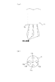
一方、図3は、第2燃料噴射弁70の先端部71の外観を示す側面図(図3(a))と正面図(図3(b))である。両図3(a)、図3(b)に示すように、第2燃料噴射弁70は、その先端部71の頂面72に5つの噴射口72a、72b、72c、72d及び72eを有する。各噴射口72a、72b、72c、72d、72eから噴射される低オクタン価燃料の噴霧は、燃焼室13(図1参照)内において、放射状に直進し、複数(本実施の形態では5つ)の噴霧の塊として点在することになる。
〔燃料噴射制御の概要〕
上述したように、吸気ポート41内に高オクタン価燃料を噴射することのできる第1燃料噴射弁60と、低オクタン価燃料を噴射して燃焼室13内に複数の燃料噴霧の塊を点在させることのできる第2燃料噴射弁70とを備えたエンジン1は、以下に説明する制御構造を採用して燃料噴射を実行し、機関燃焼を行う。
【0022】
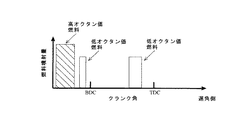
図4は、エンジン1のクランク角を横軸にとり、エンジン1の吸気行程から圧縮行程に亘る期間中、第1燃料噴射弁60を通じて供給される高オクタン価燃料の量(単位時間当たり噴射量)の推移と、第2燃料噴射弁70を通じて供給される低オクタン価燃料の量(単位時間当たり噴射量)の推移とを示すチャートである。
【0023】
同図4に示すように、第1の実施の形態におけるエンジン1は、吸気行程においてピストン12が下死点(最下点)BDCに到達する時点よりも前に、第1燃料噴射弁60を通じ吸気ポート41内に高オクタン価燃料を噴射供給する。また、圧縮行程においてピストン12が上死点(最上点)TDCに到達する時点、或いはその時点よりも少し前に(クランク角にしてBDC60°以降が好ましい。)、第2燃料噴射弁70を通じ燃焼室13内に低オクタン価燃料を噴射供給する。
【0024】
図5には、第1燃料噴射弁60を通じて供給される高オクタン価燃料の動態と、第2燃料噴射弁70を通じて供給される低オクタン価燃料の動態とを模式的に示す。
【0025】
先ず、図5(a)に示すように、吸気行程において、第1燃料噴射弁60を通じ吸気ポート41内に高オクタン価燃料が噴射供給される。すると、高オクタン価燃料の噴霧が燃焼室13内で拡散し、略均一に分布するようになる(図5(b))。
【0026】
続く圧縮行程において、吸気弁19が閉じ、ピストン12が上昇することによって、燃焼室13内の圧力が上昇する。ここで、第2燃料噴射弁70を通じ低オクタン価燃料が燃焼室13内に複数方向に噴射供給される(図5(c))。すると、燃焼室13内において、高オクタン価燃料が略均一に拡散した雰囲気中に、低オクタン価燃料の噴霧の小さな塊が点在するようになる(図5(d))。
【0027】
そして、燃焼室13内で圧縮され高温となった混合気中で、これら低オクタン価燃料の噴霧の塊が自然発火(自点火)することにより、混合気全体が爆発的に燃焼し、エンジン出力を発生するに至る。
【0028】
ここで、例えば燃焼室の天井の中央部に備えられた点火プラグ用い、燃焼室内に供給されるガソリン及び空気の混合気に点火する従来の機関燃焼方法では、点火プラグを起点として火炎が伝播し、燃焼室の周縁部に到達することで燃焼が完了する。このため、燃焼室の周縁部に存在する未燃の混合気(末端ガス)が点火プラグから拡がる火炎(圧力波)によって圧縮され、点火プラグを起点として伝播する火炎が燃焼室の周縁部に到達する前に自己点火し、いわゆるノッキングを発生させていた。
【0029】
この点、本実施の形態におけるエンジン1は、燃焼室13内において、高オクタン価燃料による高温の雰囲気を形成し、その雰囲気中に低オクタン価燃料の噴霧の塊を点在させて自然発火を促す。すなわち、爆発行程(膨張行程)において、燃焼室13内の複数個所を起点として火炎が拡がるため、実質的な燃焼速度が上がり、ノッキングが発生する前に燃焼を完了することができる。
【0030】
なお、第2燃料噴射弁70を通じ燃焼室13内に噴射供給される低オクタン価燃料の量は、第1燃料噴射弁60を通じ吸気ポート41内に噴射供給される高オクタン価燃料の量の20%(体積比率)以下とするのが好ましい。
【0031】
(第2の実施の形態)
次に、本発明を車載エンジンに適用した第2の実施の形態について、上記第1の実施の形態と異なる点を中心に説明する。なお、当該第2の実施の形態のエンジンは、ハードウエアとして、第1の実施の形態で説明したエンジン1と同等の構成を備える。そこで、エンジン自体も含め、各種構成要素について第1の実施の形態と同一の部材番号を用いることにより、ここでの重複する記載は省略する。
【0032】
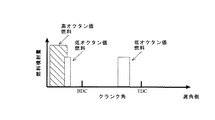
図6は、エンジン1のクランク角を横軸にとり、エンジン1の吸気行程から圧縮行程に亘る期間中、第1燃料噴射弁60を通じて供給される高オクタン価燃料の量(単位時間当たり噴射量)の推移と、第2燃料噴射弁70を通じて供給される低オクタン価燃料の量(単位時間当たり噴射量)の推移とを示すチャートである。
【0033】
同図6に示すように、第2の実施の形態におけるエンジン1は、吸気行程においてピストン12が下死点(最下点)BDCに到達する時点よりも前に、第1燃料噴射弁60を通じ高オクタン価燃料を噴射供給する点で、第1の実施の形態と共通する。しかし、第2燃料噴射弁70を通じた低オクタン価燃料の噴射供給を2回行う点で第1の実施の形態と異なる。
【0034】
以下、このような燃料噴射の形態を採用した場合、エンジン1の吸気行程及び排気行程において、吸気ポート41や燃焼室13内でみられる高オクタン価燃料及び低オクタン価燃料の動態について時系列的に説明する。
【0035】
(1)吸気行程において、第1燃料噴射弁60を通じ吸気ポート41内に高オクタン価燃料が噴射供給される。
【0036】
(2)次に、吸気行程の終了直前、或いは圧縮行程の初期段階において、第2燃料噴射弁70を通じ燃焼室13内に低オクタン価燃料が噴射供給される。これにより、燃焼室13内では、高オクタン価燃料が略均一に混合・拡散した混合気中に、低オクタン価燃料の濃度の高い部分が局所的に存在することになる。
【0037】
(3)圧縮行程の後期には、燃焼室13内の低オクタン価燃料の濃度の高い部分に、再度、低オクタン価燃料が噴射供給される。
【0038】
(4)燃焼室13内で圧縮され高温となった混合気のうち、とくに局所的にオクタン価が低くなっている部分(高オクタン価燃料と低オクタン価燃料とが混在する部分)に供給された低オクタン価燃料の噴霧の塊が自然発火(自点火)することにより、混合気全体が爆発的に燃焼して、エンジン出力を発生するに至る。
【0039】
本実施の形態によれば、低オクタン価燃料の1回目の噴射供給により、局所的にオクタン価の低い部分を点在させる。そして、低オクタン価燃料の2回目の噴射供給では、低オクタン価燃料の濃度の高い部分に再度低オクタン価燃料の噴霧を供給し自然発火を促す。このため、圧縮行程の後期において噴射供給される低オクタン価燃料(点在する噴霧の塊)の点火性が高まる。このような噴射形態を採用することにより、とくにエンジン負荷が低く燃料の着火遅れが生じやすい条件下で、圧縮行程の後期に噴射供給される低オクタン価燃料の着火遅れを効果的に防止することができる。
【0040】
(第3の実施の形態)
次に、本発明を車載エンジンに適用した第3の実施の形態について、上記各実施の形態と異なる点を中心に説明する。なお、当該第3の実施の形態のエンジンもまた、ハードウエアとして、第1の実施の形態で説明したエンジン1と同等の構成を備える。そこで、エンジン自体も含め、各種構成要素について第1の実施の形態と同一の部材番号を用いることにより、ここでの重複する記載は省略する。
【0041】
図7は、エンジン1のクランク角を横軸にとり、エンジン1の吸気行程から圧縮行程に亘る期間中、第1燃料噴射弁60を通じて供給される高オクタン価燃料の量(単位時間当たり噴射量)の推移と、第2燃料噴射弁70を通じて供給される低オクタン価燃料の量(単位時間当たり噴射量)の推移とを示すチャートである。
【0042】
同図7に示すように、第3の実施の形態におけるエンジン1は、吸気行程においてピストン12が下死点(最下点)BDCに到達する時点よりも前に、第1燃料噴射弁60を通じ高オクタン価燃料を噴射供給する点では、第1の実施の形態と共通する。しかし、第2燃料噴射弁70を通じた低オクタン価燃料の噴射供給を圧縮行程において2回行う点で第1の実施の形態と異なる。
【0043】
以下、このような燃料噴射の形態を採用した場合、エンジン1の吸気行程及び排気行程において、吸気ポート41や燃焼室13内でみられる高オクタン価燃料及び低オクタン価燃料の動態について時系列的に説明する。
【0044】
(1)吸気行程において、第1燃料噴射弁60を通じ吸気ポート41内に高オクタン価燃料が噴射供給される。
【0045】
これにより、燃焼室13内において、高オクタン価燃料が略均一に混合・拡散した混合気が形成される。
【0046】
(2)この後、圧縮行程に、第2燃料噴射弁70を通じ、低オクタン価燃料が連続的に2回噴射供給される。
【0047】
ここで、第2燃料噴射弁70を通じた1回の噴射供給により、低オクタン価燃料の噴霧の塊が例えば5個形成されると仮定すれば、連続して2回の噴射供給を行うことにより、低オクタン価燃料の噴霧の塊が計10個形成されることになる。
【0048】
(3)燃焼室13内で圧縮され高温となった混合気中において、計10個存在する低オクタン価燃料の噴霧の塊が自然発火(自点火)することにより、混合気全体が爆発的に燃焼し、エンジン出力を発生するに至る。
【0049】
このように、本実施の形態によれば、低オクタン価燃料の噴射供給を連続して2回行うことで、第2燃料噴射弁70の構造の複雑化や設置数の増大を伴うことなく、燃焼室13内に形成される低オクタン価燃料の噴霧の塊の数を倍増させる(調整する)ことができる。
【0050】
(第4の実施の形態)
次に、本発明を車載エンジンに適用した第4の実施の形態について、上記各実施の形態と異なる点を中心に説明する。なお、当該第4の実施の形態のエンジンもまた、ハードウエアとして、第1の実施の形態で説明したエンジン1と同等の構成を備える。そこで、エンジン自体も含め、各種構成要素について第1の実施の形態と同一の部材番号を用いることにより、ここでの重複する記載は省略する。
【0051】
図8は、エンジン1のクランク角を横軸にとり、エンジン1の吸気行程から圧縮行程に亘る期間中、第1燃料噴射弁60を通じて供給される高オクタン価燃料の量(単位時間当たり噴射量)の推移と、第2燃料噴射弁70を通じて供給される低オクタン価燃料の量(単位時間当たり噴射量)の推移とを示すチャートである。
【0052】
同図8に示すように、第4の実施の形態におけるエンジン1は、吸気行程においてピストン12が下死点(最下点)BDCに到達する時点よりも前に、第1燃料噴射弁60を通じ高オクタン価燃料を噴射供給する点では、第1の実施の形態と共通する。しかし、第2燃料噴射弁70を通じた低オクタン価燃料の噴射供給を圧縮行程と爆発行程(膨張行程)に各1回ずつ行う点で第1の実施の形態と異なる。
【0053】
以下、このような燃料噴射の形態を採用した場合、エンジン1の吸気行程及び排気行程において、吸気ポート41や燃焼室13内でみられる高オクタン価燃料及び低オクタン価燃料の動態について時系列的に説明する。
【0054】
(1)吸気行程において、第1燃料噴射弁60を通じ吸気ポート41内に高オクタン価燃料が噴射供給される。
【0055】
これにより、燃焼室13内において、高オクタン価燃料が略均一に混合・拡散した混合気が形成される。
【0056】
(2)この後圧縮行程において、第2燃料噴射弁70を通じ、低オクタン価燃料の1回目の噴射供給がなされる。なお、この低オクタン価燃料の1回目の噴射供給は、第2燃料噴射弁70の先端部71に設けられた5つの噴射口のうち、中央の噴射口72aのみを通じて行われるように設定しておく。
【0057】
(3)燃焼室13内で圧縮され高温となった混合気に噴射供給された低オクタン価燃料の噴霧の塊が自然発火(自点火)することにより、低オクタン価燃料の噴霧の塊を起点とした燃料の爆発が始まる。そして、燃料の爆発に伴い火炎(圧力波)が燃焼室13の周縁部に向かって伝播する。
【0058】
(4)次に、爆発行程(膨張行程)が終了する前に、第2燃料噴射弁70の先端部71に設けられた5つの噴射口のうち、噴射口72aの周囲に設けられた噴射口72b、72c、72d及び72eを通じて低オクタン価燃料を再度噴射供給する。
【0059】
これにより、噴射口72aを通じて噴射された燃料噴霧の塊を起点として、燃料の爆発に伴い火炎(圧力波)が燃焼室13の周縁部に向かって伝播する過程で、燃焼室13の周縁部近傍に存在する未燃の高オクタン価燃料に向かって低オクタン価燃料の噴霧が供給されることになる。これにより、燃焼室13の周縁部近傍に存在する未燃の高オクタン価燃料の燃焼が始まるタイミングが早まり、ノッキングの発生が効果的に防止される。
【0060】
(第5の実施の形態)
次に、本発明を車載エンジンに適用した第5の実施の形態について、上記第1の実施の形態と異なる点を中心に説明する。なお、当該第5の実施の形態のエンジンは、ハードウエアとして、第1の実施の形態で説明したエンジン1と同等の構成を備える。そこで、エンジン自体も含め、各種構成要素について第1の実施の形態と同一の部材番号を用いることにより、ここでの重複する記載は省略する。
【0061】
図9は、エンジン1のクランク角を横軸にとり、エンジン1の吸気行程から圧縮行程に亘る期間中、第1燃料噴射弁60を通じて供給される高オクタン価燃料の量(単位時間当たり噴射量)の推移と、第2燃料噴射弁70を通じて供給される低オクタン価燃料の量(単位時間当たり噴射量)の推移とを示すチャートである。
【0062】
同図9に示すように、第5の実施の形態におけるエンジン1は、吸気行程においてピストン12が下死点(最下点)BDCに到達する時点よりも前に、第1燃料噴射弁60を通じ高オクタン価燃料を噴射供給する点で第1の実施の形態と共通する。しかし、第2燃料噴射弁70を通じた低オクタン価燃料の噴射供給を2回行う点で第1の実施の形態と異なる。
【0063】
以下、このような燃料噴射の形態を採用した場合、エンジン1の吸気行程及び排気行程において、吸気ポート41や燃焼室13内でみられる高オクタン価燃料及び低オクタン価燃料の動態について時系列的に説明する。
【0064】
(1)吸気行程において、第1燃料噴射弁60を通じ吸気ポート41内に高オクタン価燃料が噴射供給される。また、同じ吸気行程において、第2燃料噴射弁70を通じ燃焼室13内に低オクタン価燃料が噴射供給される。
【0065】
これにより、高オクタン価燃料及び低オクタン価燃料の混合気(両者の中間のオクタン価の燃料蒸気)が燃焼室13内に形成される。
【0066】
(2)吸気行程の終了直前、或いは圧縮行程の初期段階において、第2燃料噴射弁70を通じ燃焼室13内に低オクタン価燃料が噴射供給される。
【0067】
これにより、燃焼室13内において、高オクタン価燃料及び低オクタン価燃料が略均一に混合・拡散した混合気中に、低オクタン価燃料の噴霧の小さな塊が点在するようになる。
【0068】
(3)この後、燃焼室13内において、高オクタン価燃料及び低オクタン価が略均一に混合・拡散した混合気中に、再度、低オクタン価燃料が噴射供給され、その噴霧の塊が自然発火(自点火)することにより、混合気全体が爆発的に燃焼して、エンジン出力を発生するに至る。
【0069】
このように、本実施の形態では、吸気行程から圧縮行程の初期にかけ、高オクタン価燃料及び低オクタン価燃料の各々を予め燃焼室13内に供給し、実質的に両者の中間のオクタン価を有する燃料の蒸気を燃焼室13内に満たす。これにより、圧縮行程の後期において噴射供給される低オクタン価燃料(点在する噴霧の塊)の点火性が高まり、燃焼速度が全体として高くなる。この結果、燃料(点在する噴霧の塊)の着火遅れが効果的に防止されるようになる。
【0070】
なお、吸気行程から圧縮行程の初期にかけて燃焼室13内に満たされる燃料のオクタン価が低くなると、点火性が高まる反面、点火タイミングの制御が困難になる。このため、吸気行程から圧縮行程の初期にかけて燃焼室13内に満たされる燃料のオクタン価(吸気行程から圧縮行程の初期にかけて供給する高オクタン価燃料の量と低オクタン価燃料の量との比率)としては、点火性と点火タイミングの制御性とを両立して最適化できる数値を設定するのが好ましい。
【0071】
また、このように点火性と点火タイミングの制御性とを両立して最適化できる数値は、例えばエンジン負荷等の運転条件によって異なる。そこで、吸気行程から圧縮行程の初期にかけて供給する高オクタン価燃料の量と、低オクタン価燃料の量の比率を、エンジン負荷等に応じて可変制御するようにしてもよい。例えば、エンジン負荷が低くなるほど燃料の点火性は低くなり、着火遅れが生じやすくなるため、吸気行程から圧縮行程の初期にかけて供給する低オクタン価燃料の量を多くすればよい。
【0072】
また、吸気行程から圧縮行程の初期にかけて供給する低オクタン価燃料の噴射タイミング(以下、低オクタン価燃料の1回目噴射タイミングという)が遅くなると、燃焼室13内における高オクタン価燃料及び低オクタン価燃料の混合が遅れる。すると、低オクタン価燃料が再度噴射される際、燃焼室13内に高オクタン価燃料と低オクタン価燃料とが不均一に分布することになる。そして、両者の混合状態が不均一であるほど、後に噴射供給される低オクタン価燃料(噴霧の塊)の点火性は低下し、燃料の燃焼速度は全体として低くなる。すなわち、低オクタン価燃料の1回目噴射タイミングを可変とし、燃料の点火性や燃焼速度を制御してもよい。
【0073】
(第6の実施の形態)
次に、本発明を車載エンジンに適用した第5の実施の形態について、上記第1の実施の形態と異なる点を中心に説明する。なお、当該第5の実施の形態のエンジンは、ハードウエアとして、第1の実施の形態で説明したエンジン1と同等の構成を備える。そこで、エンジン自体も含め、各種構成要素について第1の実施の形態と同一の部材番号を用いることにより、ここでの重複する記載は省略する。
【0074】
第6の実施の形態では、第1燃料噴射弁60及び第2燃料噴射弁70を通じて行う燃料噴射の形態をエンジン1の運転領域に応じて変更する。
【0075】
すなわち、図10に示すように、エンジン1は、理論空燃比での運転が可能な全運転領域を領域A、領域B、領域Cの3つに区画し、各領域毎に異なる燃料噴射の形態を採用する。
【0076】
そして例えば、エンジン負荷が最も高い領域Aでは、上記第1の実施の形態で説明した燃料噴射の形態(図4参照)を採用し、燃料の点火性の向上を優先的に図るようにする。また、エンジン負荷が最も低い領域Cでは、上記第5の実施の形態で説明した燃料噴射の形態(図9)を採用し、エンジン負荷が高くなるほど吸気行程から圧縮行程の初期にかけて供給する低オクタン価燃料の量を少なくすればよい。また、領域A及び領域Cの中間にあたる領域Bでは、基本的には領域Cと同じく上記第5の実施の形態で説明した燃料噴射の形態(図9)を採用しつつ、吸気行程から圧縮行程の初期にかけて供給する低オクタン価燃料の噴射タイミング(以下、低オクタン価燃料の1回目噴射タイミングという)が遅くなるように制御すればよい。
【0077】
このような制御構造を適用することにより、エンジンの運転条件に応じて、燃料の点火性と点火タイミング(着火遅れ)の制御性とを併せて最適化することができる。これにより、2種の燃料噴射弁60,70を通じた各種燃料噴射の形態によるノッキングの抑制効果を、一層効果的に活用することができる。
【0078】
実際、エンジン負荷及びエンジン回転数に基づいて、燃料噴射の形態を領域A,B,Cの3種に区画することで、ノッキングを発生させることなく理論空燃比で運転することの可能な領域を、実線で囲まれた領域から破線で囲まれた領域まで拡張できるようになることが、発明者らによって確認されている(図10参照)。
【0079】
(第7の実施の形態)
次に、本発明を車載エンジンに適用した第7の実施の形態について、上記第1の実施の形態と異なる点を中心に説明する。なお、当該第7の実施の形態のエンジンの構成要素であって、第1の実施の形態で説明したエンジン1と同等の構造及び機能を備えるものについては、第1の実施の形態と同一の部材番号を用いることにより、ここでの重複する記載は省略する。
【0080】
図11に示すように、第7の実施の形態のエンジン1Aは、吸気ポート41内に高オクタン価燃料を噴射供給できる第1燃料噴射弁60と、燃焼室13内に燃料を噴射供給できる第2燃料噴射弁70とを備える点では、エンジン1と共通する。その一方、燃焼室13内に点火プラグ90を備える点でエンジン1と異なる。点火プラグ90は、ECU80の指令信号に基づき電気火花を発生させ、燃焼室13内に供給される燃料及び空気の混合気に点火する機能を有する。
【0081】
このようなハードウエア構成を備えたエンジン1は、機関運転に際して以下のような燃料噴射の形態を採用する。
【0082】
(1)吸気行程において、第1燃料噴射弁60を通じ吸気ポート41内に高オクタン価燃料が噴射供給される。
【0083】
これにより、燃焼室13内において、高オクタン価燃料が略均一に混合・拡散した混合気が形成される。
【0084】
(2)この後圧縮行程において、第2燃料噴射弁70を通じ、低オクタン価燃料の1回目の噴射供給がなされる。
【0085】
(3)燃焼室13内で圧縮され高温となった混合気に噴射供給された低オクタン価燃料の噴霧の塊が自然発火(自点火)することにより、低オクタン価燃料の噴霧の塊を起点とした燃料の爆発が始まる。そして、燃料の爆発に伴い火炎(圧力波)が燃焼室13の周縁部に向かって伝播する。
【0086】
(4)次に、爆発行程(膨張行程)が終了する前に、点火プラグ90に電気火花を発生させる。
【0087】
すなわち、本実施の形態では、爆発行程(膨張行程)において、噴射口72aを通じて噴射された燃料噴霧の塊を起点とし、火炎(圧力波)が燃焼室13内を伝播する過程において、未燃の高オクタン価燃料を点火プラグ90によって点火することで、末端ガス(未燃の高オクタン価燃料)の燃焼が始まるタイミングを早める。この結果、ノッキングの発生が効果的に防止される。
【0088】
なお、本実施の形態と逆の手順を採用することもできる。すなわち、点火プラグ90による混合気の点火を最初に行い、火炎(圧力波)が燃焼室13内を伝播する過程において、末端ガス(未燃の高オクタン価燃料)中に低オクタン価燃料の燃料噴霧の塊を形成することにより、末端ガスの燃焼を早めるようにしてもよい。
【0089】
(ハードウエア構成の変形例)
図12及び図13には、上記各実施の形態にかかる制御構造を適用することのできるハードウエア構成の変形例を示す。すなわち、図12に示すエンジン1Bや図13に示すエンジン1Cの如く、ピストン12の頭頂面12aに、リセスを設け、第2燃料噴射弁70から噴射される燃料の噴霧が、爆発の起点(核)として最適な形態の塊を形成するようにしてもよい。
【0090】
【発明の効果】
以上説明したように、本発明によれば、実質的な燃焼速度を最適化することにより、ノッキングが発生する前に燃焼を完了することができる。その結果、ノッキングの発生を効果的に防止することができる。
【図面の簡単な説明】
【図1】本発明の第1の実施の形態におけるエンジンを概略的に示す構成図。
【図2】同実施の形態における第1燃料噴射弁の先端部の外観を示す側面図等。
【図3】同実施の形態における第2燃料噴射弁の先端部の外観を示す側面図等。
【図4】同実施の形態における高オクタン価燃料の噴射供給量の推移と、低オクタン価燃料の噴射供給量の推移とを示すチャート。
【図5】同実施の形態における第1燃料噴射弁を通じて供給される高オクタン価燃料の動態と、第2燃料噴射弁を通じて供給される低オクタン価燃料の動態とを示す模式図。
【図6】本発明の第2の実施の形態における高オクタン価燃料の噴射供給量の推移と、低オクタン価燃料の噴射供給量の推移とを示すチャート。
【図7】本発明の第3の実施の形態における高オクタン価燃料の噴射供給量の推移と、低オクタン価燃料の噴射供給量の推移とを示すチャート。
【図8】本発明の第4の実施の形態における高オクタン価燃料の噴射供給量の推移と、低オクタン価燃料の噴射供給量の推移とを示すチャート。
【図9】本発明の第5の実施の形態における高オクタン価燃料の噴射供給量の推移と、低オクタン価燃料の噴射供給量の推移とを示すチャート。
【図10】本発明の第6の実施の形態において、燃料噴射の形態を決定するために、エンジン負荷及びエンジン回転数によって区画された3つの運転領域を示すマップ。
【図11】本発明の第7の実施の形態におけるエンジンを概略的に示す構成図。
【図12】本発明の第8の実施の形態におけるエンジンを概略的に示す構成図。
【図13】同実施の形態における他のエンジンを概略的に示す構成図。
【符号の説明】
1 エンジン(内燃機関)
10 エンジン本体
10a シリンダブロック
10b シリンダヘッド
11 シリンダ
12 ピストン
12a 頭頂面
13 燃焼室
14 コンロッド
15 クランクシャフト
19 吸気弁
19a 軸部材
19b 弁体
20 排気弁
20a 軸部材
20b 弁体
31 燃焼室
41 吸気ポート
51 排気ポート
60 第1燃料噴射弁
70 第2燃料噴射弁
61 先端部
62 頂面
62a 噴射口
71 先端部
72 頂面
72a、72b、72c、72d、72e 噴射口
90 点火プラグ[0001]
TECHNICAL FIELD OF THE INVENTION
The present invention relates to an internal combustion engine that performs engine combustion by supplying a plurality of types of fuels having different octane numbers to a combustion chamber.
[0002]
[Prior art]
Generally, in a gasoline internal combustion engine, an engine output is generated by igniting and burning a mixture of fuel and air supplied into a combustion chamber using an ignition plug.
[0003]
[Patent Document 1]
JP 2000-179368 A
[0004]
[Problems to be solved by the invention]
By the way, for example, when an ignition plug is provided at the center of the ceiling of a cylindrical combustion chamber to ignite an air-fuel mixture, the flame propagates from the ignition plug toward the periphery of the combustion chamber. At this time, the unburned air-fuel mixture (end gas) present at the periphery of the combustion chamber is compressed by the flame (pressure wave) expanding from the spark plug, and the flame propagating from the ignition plug as a starting point reaches the periphery of the combustion chamber. Self-ignite before The self-ignition of the terminal gas is called knocking, and causes problems such as generation of abnormal noise and deterioration of engine durability.
[0005]
The present invention has been made in view of such circumstances, and an object of the present invention is to provide an internal combustion engine that can effectively prevent knocking.
[0006]
[Means for Solving the Problems]
To achieve the above object, the present invention provides (1) first fuel supply means for supplying high octane fuel to a combustion chamber of an internal combustion engine, and direct injection and supply of low octane fuel to the combustion chamber, And a second fuel supply means for forming a high octane fuel atmosphere in the combustion chamber through the first fuel supply means. And control means for spraying low-octane fuel spray at a plurality of locations in the combustion chamber.
[0007]
According to this configuration, engine combustion is performed by forming a high-temperature atmosphere with a high octane fuel in the combustion chamber and scattering lump of spray of the low octane fuel in the atmosphere to promote spontaneous ignition. Become. That is, in the explosion stroke (expansion stroke), the flame spreads from a plurality of points in the combustion chamber, so that the combustion speed is substantially increased, and the combustion can be completed before knocking occurs.
(2) The control means may supply the low octane fuel to the combustion chamber through the second fuel supply means during an intake stroke and a compression stroke of the engine.
[0008]
According to this configuration, for example, under conditions where the engine load is low and fuel ignition delay is likely to occur, ignition delay of low octane number fuel injected and supplied in the latter half of the compression stroke can be effectively prevented.
(3) The control means may supply the low octane fuel to the combustion chamber through the second fuel supply means at least twice in the compression stroke.
[0009]
According to this configuration, by continuously performing the injection supply of the low octane number fuel a plurality of times, the low fuel formed in the combustion chamber can be formed without complicating the structure of the second fuel supply means and increasing the number of installations. The number of lumps of spray of octane fuel can be adjusted.
(4) Further, the control means may supply the low octane number fuel into the combustion chamber through the second fuel supply means during the compression stroke and the expansion stroke.
[0010]
According to this configuration, the flame (pressure wave) propagates toward the peripheral portion of the combustion chamber as the fuel explodes, starting from the fuel spray mass formed through the second fuel supply means. The spray of the low octane fuel is supplied toward the unburned high octane fuel present near the peripheral portion of the fuel cell. Thus, the timing of starting the combustion of the unburned high-octane fuel present near the periphery of the combustion chamber is advanced, and the occurrence of knocking is effectively prevented.
(5) Another aspect of the present invention is a method for combustion of an internal combustion engine, wherein a lump of spray of a low octane fuel is scattered in an atmosphere of a high octane fuel formed in a combustion chamber, and the spray is sprayed in a compression stroke. The main point is that combustion is performed by self-igniting a lump of.
[0011]
According to this configuration, engine combustion is performed by forming a high-temperature atmosphere with a high octane fuel in the combustion chamber and scattering lump of spray of the low octane fuel in the atmosphere to promote spontaneous ignition. Become. That is, in the explosion stroke (expansion stroke), the flame spreads from a plurality of points in the combustion chamber, so that the combustion speed is substantially increased, and the combustion can be completed before knocking occurs.
[0012]
The engine combustion can be performed by appropriately combining the above-described configurations.
[0013]
BEST MODE FOR CARRYING OUT THE INVENTION
(First Embodiment)
Hereinafter, a first embodiment in which the present invention is applied to an in-vehicle engine will be described. [Basic structure and function of engine]
As shown in FIG. 1, an internal combustion engine (hereinafter referred to as an engine) 1 includes a plurality of cylinders (only one cylinder is shown), and has four cycles of an intake stroke, a compression stroke, an explosion stroke (expansion stroke), and an exhaust stroke. To get the output.
[0014]
The
[0015]
Further, the
[0016]
The
[0017]
The
[0018]
Further, the
[0019]
The
[0020]
The
[Functions of First Fuel Injection Valve and Second Fuel Injection Valve]
FIG. 2 is a side view (FIG. 2A) and a front view (FIG. 2B) showing the appearance of the
[0021]
On the other hand, FIG. 3 is a side view (FIG. 3A) and a front view (FIG. 3B) showing the appearance of the
[Overview of fuel injection control]
As described above, the first
[0022]
FIG. 4 shows the crank angle of the engine 1 on the horizontal axis, and shows the amount of high-octane fuel (injection amount per unit time) supplied through the first
[0023]
As shown in FIG. 4, the engine 1 in the first embodiment passes through the first
[0024]
FIG. 5 schematically shows the dynamics of the high octane fuel supplied through the first
[0025]
First, as shown in FIG. 5A, high octane fuel is injected into the
[0026]
In the subsequent compression stroke, the
[0027]
Then, in the air-fuel mixture compressed in the
[0028]
Here, in a conventional engine combustion method for igniting a mixture of gasoline and air supplied into the combustion chamber, for example, using a spark plug provided at the center of the ceiling of the combustion chamber, the flame propagates from the ignition plug as a starting point. When the fuel reaches the peripheral portion of the combustion chamber, the combustion is completed. For this reason, the unburned air-fuel mixture (end gas) present at the periphery of the combustion chamber is compressed by the flame (pressure wave) spreading from the spark plug, and the flame propagating from the ignition plug as a starting point reaches the periphery of the combustion chamber. Self-ignition before firing, so-called knocking occurred.
[0029]
In this regard, the engine 1 in the present embodiment forms a high-temperature atmosphere with high-octane fuel in the
[0030]
The amount of low octane fuel injected and supplied into the
[0031]
(Second embodiment)
Next, a second embodiment in which the present invention is applied to an in-vehicle engine will be described, focusing on differences from the first embodiment. The engine of the second embodiment has the same hardware configuration as the engine 1 described in the first embodiment. Therefore, by using the same member numbers as in the first embodiment for the various components including the engine itself, the duplicated description will be omitted.
[0032]
FIG. 6 shows the crank angle of the engine 1 on the horizontal axis, and shows the amount (injection amount per unit time) of the high octane fuel supplied through the first
[0033]
As shown in FIG. 6, the engine 1 according to the second embodiment passes through the first
[0034]
Hereinafter, when such a fuel injection mode is adopted, the dynamics of the high octane fuel and the low octane fuel observed in the
[0035]
(1) In the intake stroke, high octane fuel is injected and supplied into the
[0036]
(2) Next, immediately before the end of the intake stroke or at the initial stage of the compression stroke, low octane fuel is injected and supplied into the
[0037]
(3) In the latter half of the compression stroke, the low octane fuel is injected again into the high octane fuel concentration portion in the
[0038]
(4) The low octane number supplied to a portion of the air-fuel mixture which has been compressed in the
[0039]
According to the present embodiment, a portion having a low octane number is locally scattered by the first injection supply of the low octane number fuel. Then, in the second injection supply of the low octane fuel, the spray of the low octane fuel is supplied again to the portion where the concentration of the low octane fuel is high to promote spontaneous ignition. For this reason, the ignitability of the low octane fuel (injected lump of spray) injected and supplied in the latter half of the compression stroke is enhanced. By adopting such an injection mode, it is possible to effectively prevent the ignition delay of the low octane number fuel injected and supplied in the latter half of the compression stroke, particularly under conditions where the engine load is low and fuel ignition delay is likely to occur. it can.
[0040]
(Third embodiment)
Next, a third embodiment in which the present invention is applied to an in-vehicle engine will be described, focusing on differences from the above embodiments. The engine according to the third embodiment also has the same hardware configuration as the engine 1 described in the first embodiment. Therefore, by using the same member numbers as in the first embodiment for the various components including the engine itself, the duplicated description will be omitted.
[0041]
FIG. 7 shows the crank angle of the engine 1 on the horizontal axis, and shows the amount (injection amount per unit time) of the high octane fuel supplied through the first
[0042]
As shown in FIG. 7, the engine 1 according to the third embodiment passes through the first
[0043]
Hereinafter, when such a fuel injection mode is adopted, the dynamics of the high octane fuel and the low octane fuel observed in the
[0044]
(1) In the intake stroke, high octane fuel is injected and supplied into the
[0045]
As a result, an air-fuel mixture in which the high octane fuel is substantially uniformly mixed and diffused is formed in the
[0046]
(2) Thereafter, during the compression stroke, the low-octane fuel is continuously injected and supplied twice through the second
[0047]
Here, assuming that, for example, five injection lumps of low octane fuel are formed by one injection supply through the second
[0048]
(3) In the air-fuel mixture compressed in the
[0049]
As described above, according to the present embodiment, by performing the injection and supply of the low octane fuel twice consecutively, the combustion of the second
[0050]
(Fourth embodiment)
Next, a fourth embodiment in which the present invention is applied to an in-vehicle engine will be described, focusing on differences from the above embodiments. The engine of the fourth embodiment also has the same hardware configuration as the engine 1 described in the first embodiment. Therefore, by using the same member numbers as those of the first embodiment for the various components including the engine itself, the duplicate description will be omitted.
[0051]
FIG. 8 shows the crank angle of the engine 1 on the horizontal axis, and shows the amount (injection amount per unit time) of the high-octane fuel supplied through the first
[0052]
As shown in FIG. 8, the engine 1 according to the fourth embodiment passes through the first
[0053]
Hereinafter, when such a fuel injection mode is adopted, the dynamics of the high octane fuel and the low octane fuel observed in the
[0054]
(1) In the intake stroke, high octane fuel is injected and supplied into the
[0055]
As a result, an air-fuel mixture in which the high octane fuel is substantially uniformly mixed and diffused is formed in the
[0056]
(2) Thereafter, in the compression stroke, the first injection supply of low octane fuel is performed through the second
[0057]
(3) The low octane number fuel spray injected into the high temperature air-fuel mixture compressed in the
[0058]
(4) Next, before the explosion stroke (expansion stroke) ends, of the five nozzles provided at the
[0059]
Accordingly, in a process in which the flame (pressure wave) propagates toward the peripheral portion of the
[0060]
(Fifth embodiment)
Next, a fifth embodiment in which the present invention is applied to an in-vehicle engine will be described, focusing on differences from the first embodiment. Note that the engine of the fifth embodiment has the same hardware configuration as the engine 1 described in the first embodiment. Therefore, by using the same member numbers as in the first embodiment for the various components including the engine itself, the duplicated description will be omitted.
[0061]
FIG. 9 shows the crank angle of the engine 1 on the horizontal axis, and shows the amount (injection amount per unit time) of the high octane fuel supplied through the first
[0062]
As shown in FIG. 9, the engine 1 according to the fifth embodiment passes through the first
[0063]
Hereinafter, when such a fuel injection mode is adopted, the dynamics of the high octane fuel and the low octane fuel observed in the
[0064]
(1) In the intake stroke, high octane fuel is injected and supplied into the
[0065]
As a result, a mixture of a high octane fuel and a low octane fuel (an intermediate octane fuel vapor) is formed in the
[0066]
(2) Immediately before the end of the intake stroke or at the initial stage of the compression stroke, low octane fuel is injected and supplied into the
[0067]
As a result, in the
[0068]
(3) Thereafter, in the
[0069]
As described above, in the present embodiment, during the period from the intake stroke to the early stage of the compression stroke, each of the high octane fuel and the low octane fuel is previously supplied into the
[0070]
When the octane number of the fuel filled in the
[0071]
Further, the numerical value that can be optimized while achieving both the ignition performance and the controllability of the ignition timing in this way differs depending on the operating conditions such as the engine load. Therefore, the ratio between the amount of the high octane fuel and the amount of the low octane fuel supplied from the intake stroke to the early stage of the compression stroke may be variably controlled according to the engine load or the like. For example, the lower the engine load, the lower the ignitability of the fuel and the more likely it is for the ignition to delay. Therefore, the amount of the low octane fuel supplied from the intake stroke to the early stage of the compression stroke may be increased.
[0072]
Further, when the injection timing of the low octane fuel supplied from the intake stroke to the early stage of the compression stroke (hereinafter referred to as the first injection timing of the low octane fuel) is delayed, the mixture of the high octane fuel and the low octane fuel in the
[0073]
(Sixth embodiment)
Next, a fifth embodiment in which the present invention is applied to an in-vehicle engine will be described, focusing on differences from the first embodiment. Note that the engine of the fifth embodiment has the same hardware configuration as the engine 1 described in the first embodiment. Therefore, by using the same member numbers as in the first embodiment for the various components including the engine itself, the duplicated description will be omitted.
[0074]
In the sixth embodiment, the form of fuel injection performed through the first
[0075]
That is, as shown in FIG. 10, the engine 1 divides the entire operating region in which operation at the stoichiometric air-fuel ratio is possible into three regions A, B, and C, and forms different fuel injections for each region. Is adopted.
[0076]
For example, in the region A where the engine load is the highest, the fuel injection mode described in the first embodiment (see FIG. 4) is employed to improve the ignition performance of the fuel preferentially. In the region C where the engine load is the lowest, the fuel injection mode described in the fifth embodiment (FIG. 9) is adopted. As the engine load increases, the low octane number supplied from the intake stroke to the early stage of the compression stroke is increased. What is necessary is just to reduce the amount of fuel. In addition, in the region B, which is located between the regions A and C, basically, the fuel injection mode (FIG. 9) described in the fifth embodiment is employed similarly to the region C, and the intake stroke and the compression stroke are changed. May be controlled so that the injection timing of the low-octane fuel supplied to the initial stage (hereinafter, referred to as the first injection timing of the low-octane fuel) is delayed.
[0077]
By applying such a control structure, it is possible to optimize both the ignitability of the fuel and the controllability of the ignition timing (ignition delay) according to the operating conditions of the engine. This makes it possible to more effectively utilize the effect of suppressing knocking by various types of fuel injection through the two types of
[0078]
Actually, by dividing the fuel injection mode into three types of areas A, B, and C based on the engine load and the engine speed, an area where the engine can be operated at the stoichiometric air-fuel ratio without knocking is generated. It has been confirmed by the inventors that the present invention can be extended from a region surrounded by a solid line to a region surrounded by a broken line (see FIG. 10).
[0079]
(Seventh embodiment)
Next, a seventh embodiment in which the present invention is applied to an in-vehicle engine will be described focusing on differences from the first embodiment. Note that components of the engine of the seventh embodiment that have the same structure and function as the engine 1 described in the first embodiment are the same as those of the first embodiment. By using the member numbers, duplicate descriptions are omitted here.
[0080]
As shown in FIG. 11, an engine 1 </ b> A according to the seventh embodiment includes a first
[0081]
The engine 1 having such a hardware configuration employs the following fuel injection mode during engine operation.
[0082]
(1) In the intake stroke, high octane fuel is injected and supplied into the
[0083]
As a result, an air-fuel mixture in which the high octane fuel is substantially uniformly mixed and diffused is formed in the
[0084]
(2) Thereafter, in the compression stroke, the first injection supply of low octane fuel is performed through the second
[0085]
(3) The low octane number fuel spray injected into the high temperature air-fuel mixture compressed in the
[0086]
(4) Next, before the explosion stroke (expansion stroke) ends, an electric spark is generated in the
[0087]
That is, in the present embodiment, in the explosion stroke (expansion stroke), starting from the lump of the fuel spray injected through the
[0088]
Note that a procedure reverse to that of the present embodiment can be adopted. That is, first, the mixture is ignited by the
[0089]
(Modification of hardware configuration)
FIGS. 12 and 13 show modified examples of the hardware configuration to which the control structure according to each of the above embodiments can be applied. That is, like the engine 1B shown in FIG. 12 and the engine 1C shown in FIG. 13, a recess is provided in the top surface 12a of the
[0090]
【The invention's effect】
As described above, according to the present invention, by optimizing the substantial combustion speed, combustion can be completed before knocking occurs. As a result, occurrence of knocking can be effectively prevented.
[Brief description of the drawings]
FIG. 1 is a configuration diagram schematically showing an engine according to a first embodiment of the present invention.
FIG. 2 is a side view showing the appearance of a tip end of a first fuel injection valve in the embodiment.
FIG. 3 is a side view showing the appearance of the tip of a second fuel injection valve in the embodiment.
FIG. 4 is a chart showing a transition of an injection supply amount of a high octane number fuel and a transition of an injection supply amount of a low octane number fuel in the embodiment.
FIG. 5 is a schematic diagram showing the behavior of a high octane fuel supplied through a first fuel injection valve and the behavior of a low octane fuel supplied through a second fuel injection valve in the embodiment.
FIG. 6 is a chart showing a transition of an injection supply amount of a high octane number fuel and a transition of an injection supply amount of a low octane number fuel in the second embodiment of the present invention.
FIG. 7 is a chart showing a transition of an injection supply amount of a high octane fuel and a transition of an injection supply amount of a low octane fuel in a third embodiment of the present invention.
FIG. 8 is a chart showing a transition of an injection supply amount of a high octane number fuel and a transition of an injection supply amount of a low octane number fuel in a fourth embodiment of the present invention.
FIG. 9 is a chart showing a transition of an injection supply amount of a high octane number fuel and a transition of an injection supply amount of a low octane number fuel in a fifth embodiment of the present invention.
FIG. 10 is a map showing three operating regions divided by an engine load and an engine speed in order to determine a fuel injection mode in a sixth embodiment of the present invention.
FIG. 11 is a configuration diagram schematically showing an engine according to a seventh embodiment of the present invention.
FIG. 12 is a configuration diagram schematically showing an engine according to an eighth embodiment of the present invention.
FIG. 13 is a configuration diagram schematically showing another engine according to the embodiment.
[Explanation of symbols]
1 engine (internal combustion engine)
10 Engine body
10a cylinder block
10b cylinder head
11 cylinder
12 piston
12a top surface
13 Combustion chamber
14 Connecting rod
15 Crankshaft
19 Intake valve
19a Shaft member
19b valve body
20 Exhaust valve
20a Shaft member
20b valve body
31 Combustion chamber
41 Intake port
51 Exhaust port
60 first fuel injection valve
70 2nd fuel injection valve
61 Tip
62 Top
62a injection port
71 Tip
72 Top
72a, 72b, 72c, 72d, 72e Injection port
90 spark plug
Claims (5)
前記燃焼室内に低オクタン価燃料を直接噴射供給し、同燃料室内の複数箇所に低オクタン価燃料の噴霧を点在させる第2の燃料供給手段と、
前記第1の燃料供給手段を通じて前記燃焼室内に高オクタン価燃料の雰囲気を形成した後、前記第2の燃料供給手段を通じて前記燃焼室内の複数箇所に低オクタン価燃料の噴霧を点在させる制御手段と、
を備えることを特徴とする内燃機関。First fuel supply means for supplying high octane fuel to the combustion chamber of the internal combustion engine;
Second fuel supply means for directly injecting and supplying the low octane fuel into the combustion chamber, and spraying the low octane fuel at a plurality of locations in the fuel chamber;
Control means for forming an atmosphere of high octane fuel in the combustion chamber through the first fuel supply means, and then spraying low octane fuel spray at a plurality of locations in the combustion chamber through the second fuel supply means;
An internal combustion engine comprising:
ことを特徴とする内燃機関の燃焼方法。An internal combustion engine characterized in that combustion is performed by scattering a lump of spray of a low-octane fuel in an atmosphere of a high-octane fuel formed in a combustion chamber and self-igniting the lump of the spray in a compression stroke. Burning method.
Priority Applications (1)
| Application Number | Priority Date | Filing Date | Title |
|---|---|---|---|
| JP2002367579A JP4214774B2 (en) | 2002-12-19 | 2002-12-19 | Internal combustion engine and combustion method for internal combustion engine |
Applications Claiming Priority (1)
| Application Number | Priority Date | Filing Date | Title |
|---|---|---|---|
| JP2002367579A JP4214774B2 (en) | 2002-12-19 | 2002-12-19 | Internal combustion engine and combustion method for internal combustion engine |
Publications (2)
| Publication Number | Publication Date |
|---|---|
| JP2004197660A true JP2004197660A (en) | 2004-07-15 |
| JP4214774B2 JP4214774B2 (en) | 2009-01-28 |
Family
ID=32764430
Family Applications (1)
| Application Number | Title | Priority Date | Filing Date |
|---|---|---|---|
| JP2002367579A Expired - Fee Related JP4214774B2 (en) | 2002-12-19 | 2002-12-19 | Internal combustion engine and combustion method for internal combustion engine |
Country Status (1)
| Country | Link |
|---|---|
| JP (1) | JP4214774B2 (en) |
Cited By (9)
| Publication number | Priority date | Publication date | Assignee | Title |
|---|---|---|---|---|
| US6959693B2 (en) * | 2003-11-26 | 2005-11-01 | Toyota Jidosha Kabushiki Kaisha | Fuel injection system and method |
| JP2008240644A (en) * | 2007-03-27 | 2008-10-09 | Nissan Motor Co Ltd | Combustion control device of internal combustion engine |
| EP2020496A2 (en) | 2007-08-03 | 2009-02-04 | Nissan Motor Co., Ltd. | Combustion control of internal combustion engine |
| JP2009216004A (en) * | 2008-03-11 | 2009-09-24 | Toyota Motor Corp | Internal combustion engine |
| WO2009130777A1 (en) | 2008-04-24 | 2009-10-29 | トヨタ自動車株式会社 | Multifuel internal-combustion engine |
| JP2010190072A (en) * | 2009-02-17 | 2010-09-02 | Nissan Motor Co Ltd | Compression ignition internal combustion engine |
| JP2014206055A (en) * | 2013-04-10 | 2014-10-30 | 本田技研工業株式会社 | Control device for internal combustion engine |
| JP2015214957A (en) * | 2014-05-13 | 2015-12-03 | 本田技研工業株式会社 | Internal combustion engine control device |
| JP2017504749A (en) * | 2013-12-13 | 2017-02-09 | 周向▲進▼ZHOU, Xiangjin | Combustion control method that mixes homogeneous compression ignition and diffusion compression ignition with low octane gasoline |
-
2002
- 2002-12-19 JP JP2002367579A patent/JP4214774B2/en not_active Expired - Fee Related
Cited By (13)
| Publication number | Priority date | Publication date | Assignee | Title |
|---|---|---|---|---|
| US6959693B2 (en) * | 2003-11-26 | 2005-11-01 | Toyota Jidosha Kabushiki Kaisha | Fuel injection system and method |
| US7721703B2 (en) | 2007-03-27 | 2010-05-25 | Nissan Motor Co., Ltd. | Combustion control system for internal combustion engine |
| JP2008240644A (en) * | 2007-03-27 | 2008-10-09 | Nissan Motor Co Ltd | Combustion control device of internal combustion engine |
| JP4501950B2 (en) * | 2007-03-27 | 2010-07-14 | 日産自動車株式会社 | Combustion control device for internal combustion engine |
| EP2020496A2 (en) | 2007-08-03 | 2009-02-04 | Nissan Motor Co., Ltd. | Combustion control of internal combustion engine |
| US7603225B2 (en) | 2007-08-03 | 2009-10-13 | Nissan Motor Co., Ltd. | Combustion control of internal combustion engine |
| JP2009216004A (en) * | 2008-03-11 | 2009-09-24 | Toyota Motor Corp | Internal combustion engine |
| WO2009130777A1 (en) | 2008-04-24 | 2009-10-29 | トヨタ自動車株式会社 | Multifuel internal-combustion engine |
| US8516991B2 (en) | 2008-04-24 | 2013-08-27 | Toyota Jidosha Kabushiki Kaisha | Multi-fuel internal combustion engine |
| JP2010190072A (en) * | 2009-02-17 | 2010-09-02 | Nissan Motor Co Ltd | Compression ignition internal combustion engine |
| JP2014206055A (en) * | 2013-04-10 | 2014-10-30 | 本田技研工業株式会社 | Control device for internal combustion engine |
| JP2017504749A (en) * | 2013-12-13 | 2017-02-09 | 周向▲進▼ZHOU, Xiangjin | Combustion control method that mixes homogeneous compression ignition and diffusion compression ignition with low octane gasoline |
| JP2015214957A (en) * | 2014-05-13 | 2015-12-03 | 本田技研工業株式会社 | Internal combustion engine control device |
Also Published As
| Publication number | Publication date |
|---|---|
| JP4214774B2 (en) | 2009-01-28 |
Similar Documents
| Publication | Publication Date | Title |
|---|---|---|
| JP4100401B2 (en) | Internal combustion engine | |
| US9932883B2 (en) | Spark-ignition direct-injection engine | |
| RU2136918C1 (en) | Internal combustion engine and method of its operation | |
| JP3558370B2 (en) | Compression ignition gasoline engine | |
| CN103161587B (en) | Variable ignition type diesel-gasoline dual fuel powered combustion engine, system and method | |
| JP4407581B2 (en) | Gas fuel engine | |
| EP1983169A1 (en) | Internal Combustion Engine and Combustion Method of the Same | |
| EP1925802B1 (en) | Quick restart HCCI internal combustion engine | |
| US20020038645A1 (en) | Method for operating an internal combustion engine operated with a self-ignitable fuel | |
| JP2004239208A (en) | Engine combustion control device | |
| RU2541346C2 (en) | Method of ice operation | |
| US20130152899A1 (en) | Dual fuel combustion system based on diesel compression ignition triggered ignition control | |
| US11118528B2 (en) | Fuel injection control device for engine | |
| JP5922830B1 (en) | Gas engine | |
| JP2000120457A (en) | Diesel engine | |
| JP4214774B2 (en) | Internal combustion engine and combustion method for internal combustion engine | |
| JPH10252512A (en) | Compressed ignition internal combustion engine | |
| JP2003090239A (en) | Internal combustion engine of cylinder direct injection type | |
| JP2006316777A (en) | Internal combustion engine | |
| JP2010196517A (en) | Control device for internal combustion engine | |
| JP3952710B2 (en) | Compression self-ignition internal combustion engine | |
| JP2008157197A (en) | Cylinder injection type spark ignition internal combustion engine | |
| JP2008184970A (en) | Control device of gasoline engine | |
| GB2186913A (en) | Internal combustion engine | |
| KR20160108813A (en) | Method and control device for operating a dual-fuel engine |
Legal Events
| Date | Code | Title | Description |
|---|---|---|---|
| A621 | Written request for application examination |
Free format text: JAPANESE INTERMEDIATE CODE: A621 Effective date: 20050805 |
|
| A977 | Report on retrieval |
Free format text: JAPANESE INTERMEDIATE CODE: A971007 Effective date: 20071213 |
|
| A131 | Notification of reasons for refusal |
Free format text: JAPANESE INTERMEDIATE CODE: A131 Effective date: 20080129 |
|
| A521 | Written amendment |
Free format text: JAPANESE INTERMEDIATE CODE: A523 Effective date: 20080328 |
|
| A131 | Notification of reasons for refusal |
Free format text: JAPANESE INTERMEDIATE CODE: A131 Effective date: 20080708 |
|
| A521 | Written amendment |
Free format text: JAPANESE INTERMEDIATE CODE: A523 Effective date: 20080905 |
|
| TRDD | Decision of grant or rejection written | ||
| A01 | Written decision to grant a patent or to grant a registration (utility model) |
Free format text: JAPANESE INTERMEDIATE CODE: A01 Effective date: 20081014 |
|
| A01 | Written decision to grant a patent or to grant a registration (utility model) |
Free format text: JAPANESE INTERMEDIATE CODE: A01 |
|
| A61 | First payment of annual fees (during grant procedure) |
Free format text: JAPANESE INTERMEDIATE CODE: A61 Effective date: 20081027 |
|
| FPAY | Renewal fee payment (event date is renewal date of database) |
Free format text: PAYMENT UNTIL: 20111114 Year of fee payment: 3 |
|
| FPAY | Renewal fee payment (event date is renewal date of database) |
Free format text: PAYMENT UNTIL: 20111114 Year of fee payment: 3 |
|
| FPAY | Renewal fee payment (event date is renewal date of database) |
Free format text: PAYMENT UNTIL: 20121114 Year of fee payment: 4 |
|
| LAPS | Cancellation because of no payment of annual fees |