JP2004190478A - Tunnel reinforcing material separation detecting method and device - Google Patents
Tunnel reinforcing material separation detecting method and device Download PDFInfo
- Publication number
- JP2004190478A JP2004190478A JP2004003059A JP2004003059A JP2004190478A JP 2004190478 A JP2004190478 A JP 2004190478A JP 2004003059 A JP2004003059 A JP 2004003059A JP 2004003059 A JP2004003059 A JP 2004003059A JP 2004190478 A JP2004190478 A JP 2004190478A
- Authority
- JP
- Japan
- Prior art keywords
- strain
- optical fiber
- reinforcing material
- tunnel
- crack
- Prior art date
- Legal status (The legal status is an assumption and is not a legal conclusion. Google has not performed a legal analysis and makes no representation as to the accuracy of the status listed.)
- Granted
Links
Images


Abstract
Description
本発明は、トンネルの内壁面を補強している補強材の剥離を検知するトンネル補強材剥離検知方法及び装置に関する。 The present invention relates to a method and an apparatus for detecting peeling of a tunnel reinforcing material for detecting peeling of a reinforcing material reinforcing an inner wall surface of a tunnel.
従来、経年変化しているトンネルの検査については、全般的に目視検査と破壊検査に大きく依存している。道路トンネルのひび割れ検査は、作業者がトンネル内を徒歩または高所作業車にて移動し、目視観察による調査を中心に行なっている。また、覆工背面の空洞探査、覆工圧の測定は、コアボーリングを行ない、内視鏡などを用いて調査している。 2. Description of the Related Art Conventionally, inspection of an aged tunnel largely depends on visual inspection and destructive inspection in general. Inspections for cracks in road tunnels are conducted mainly by visual inspection, with workers walking in the tunnel or using aerial vehicles. In addition, core borings are used for exploration of cavities on the back of the lining and measurement of the lining pressure.
また鉄道トンネルでは、トンネルの新旧、構造種別に関わりなく、2年を越えない期間に1回の周期で検査、所謂全般検査を実施している。この全般検査は、主に徒歩による目視で行ない、覆工表面のひび割れの発生、レンガコンクリートブロックなど覆工材料の目地切れ及び漏水など、変状の発生及び進行の箇所を探し出すことを目的として行なわれている。 In addition, in the case of railway tunnels, inspections, so-called general inspections, are performed once every two years or less, irrespective of the type of the tunnels, new or old, and structural type. This general inspection is mainly conducted visually on foot, and is conducted with the purpose of finding cracks on the lining surface, breaks in the lining material such as brick concrete blocks, leaks of water, etc. Have been.
上記全般検査で変状などの異常が発見された箇所については、変状の原因を究明し適切な処置をとる必要から、更に詳細な検査、所謂個別作業を実施するという2段階の検査方式がとられている。 For the places where abnormalities such as abnormalities are found in the above general inspection, it is necessary to investigate the cause of the abnormalities and take appropriate measures. Has been taken.
上記のようにしてトンネルのひび割れ検査を行なった結果、補強が必要な箇所には、例えば繊維シートなどの補強材を接着剤にて固定するなどの補強工事を行なう。この補強工事を行なった箇所についても、繊維シートの剥離を上記ひび割れ検査の場合と同様に目視により検査している。 As a result of the crack inspection of the tunnel as described above, a reinforcing work such as fixing a reinforcing material such as a fiber sheet with an adhesive is performed at a place where the reinforcing is necessary. At the places where this reinforcement work was performed, the peeling of the fiber sheet was visually inspected similarly to the case of the crack inspection.
一方、最近では、補強材として電気的に導通性を有する炭素繊維シートを使用し、炭素繊維糸状の電気抵抗の変化を測定して構造物の疲労、劣化を検出するようにした構造物のモニタリング方法が考えられている(例えば、特許文献1参照。)。これは構造物の疲労、劣化状態に応じて炭素繊維シートの単糸が破断して電気抵抗が変化することを利用したものである。
上述した従来の目視によるトンネルひび割れ検査方法では、ひび割れ検査を行なう場合、トンネル内が暗いため、トンネル壁面の変状を見逃す確率が高く、アーチ部などの高所の変状を把握し難く、また、得られる検査結果に個人誤差などがあり、客観性に乏しいと共に、調査に多大な時間と費用を要するという問題がある。 In the conventional visual inspection method for tunnel cracks described above, when performing a crack inspection, since the inside of the tunnel is dark, the probability of overlooking the deformation of the tunnel wall surface is high, and it is difficult to grasp the deformation of high places such as arches, In addition, there is a problem in that the obtained test results have individual errors and the like, and the objectivity is poor.
また、トンネルのひび割れを繊維シートで補強した場合においても、その補強箇所の異常を目視により検査しなければならず、ひび割れ検査の場合と同様の問題がある。 Further, even when a crack in a tunnel is reinforced with a fiber sheet, an abnormality in the reinforced portion must be visually inspected, which has the same problem as in the crack inspection.
また、補強材として電気的に導通性を有する炭素繊維シートを使用し、炭素繊維糸状の電気抵抗の変化を測定して構造物の疲労、劣化を検知するようにした構造物のモニタリング方法は、鉄道トンネルのように架線等の電気設備が設けられる場合には導電体である炭素繊維シートを使用することに問題がある。すなわち、壁面から炭素繊維シートが剥離した場合に、この剥離した炭素繊維シートによって電気設備に短絡事故が発生する可能性があるので、電気設備が設けられているトンネルには炭素繊維シートを使用することができない。 In addition, using a carbon fiber sheet having electrical conductivity as a reinforcing material, a structure monitoring method that detects fatigue, deterioration of the structure by measuring the change in the electrical resistance of the carbon fiber thread, When electric facilities such as overhead lines are provided as in a railway tunnel, there is a problem in using a carbon fiber sheet as a conductor. That is, when the carbon fiber sheet is peeled from the wall surface, a short circuit accident may occur in the electric equipment due to the peeled carbon fiber sheet. Therefore, the carbon fiber sheet is used for a tunnel provided with the electric equipment. I can't.
本発明は上記の課題を解決するためになされたもので、トンネル内の補強箇所における補強材の剥離を遠隔地点で正確に計測し得るトンネル補強材剥離検知方法及び装置を提供することを目的とする。 The present invention has been made in order to solve the above-mentioned problems, and an object of the present invention is to provide a method and an apparatus for detecting a tunnel reinforcing material peeling which can accurately measure the peeling of a reinforcing material at a reinforcing point in a tunnel at a remote point. I do.
第1の発明は、トンネル内の壁面を補強した補強材の表面に光ファイバを固定し、前記光ファイバの歪みと位置の関係を計測して補強材の剥離を検知するトンネル補強材剥離検知方法において、前記トンネル内面の補強材の表面に光ファイバを張力をかけながらひび割れの上に一方の固定端が位置するように固定すると共に、剥離監視位置における光ファイバの歪みを歪み計測器で計測し、前記剥離監視位置の歪みが引張り歪みから圧縮歪みに変化した状態を検出して補強材の剥離を検知することを特徴とする。 According to a first aspect of the present invention, there is provided a tunnel reinforcing member peeling detecting method for fixing an optical fiber to a surface of a reinforcing material which reinforced a wall surface in a tunnel, measuring a relationship between a distortion and a position of the optical fiber, and detecting peeling of the reinforcing material. At the same time, while applying tension to the surface of the reinforcing material on the inner surface of the tunnel while fixing so that one fixed end is located on the crack, the strain of the optical fiber at the peeling monitoring position is measured with a strain measuring instrument. And detecting a state in which the strain at the peel monitoring position has changed from a tensile strain to a compressive strain to detect the peeling of the reinforcing material.
第2の発明は、トンネル内の壁面を補強した補強材の表面に光ファイバを固定し、前記光ファイバの歪と位置の関係を計測して補強材の剥離を検知するトンネル補強材剥離検知装置において、前記トンネル内面の補強材の表面に光ファイバを張力をかけながらひび割れの上に一方の固定端が位置するように固定する固定手段と、剥離監視位置における光ファイバの歪みを計測する歪み計測器と、この歪み計測器により計測された歪みを記憶する記憶手段と、前記歪み計測器により今回計測された歪と前記記憶手段に記憶された前回計測時の歪みとを比較し、計測された歪が引張り歪みから圧縮歪みに変化した状態を検出して補強材の剥離を検知する手段とを具備したことを特徴とする。 According to a second aspect of the present invention, there is provided a tunnel reinforcing member peeling detection device for fixing an optical fiber to a surface of a reinforcing material which reinforces a wall surface in a tunnel, measuring a relation between a strain and a position of the optical fiber, and detecting peeling of the reinforcing material. A fixing means for fixing the optical fiber so that one fixed end is positioned on the crack while applying tension to the surface of the reinforcing material on the inner surface of the tunnel; and a strain measurement for measuring the strain of the optical fiber at the separation monitoring position. And the storage means for storing the strain measured by the strain measuring instrument, and the strain measured this time by the strain measuring instrument is compared with the strain at the previous measurement stored in the storing means, and the strain is measured. Means for detecting a state in which the strain has changed from tensile strain to compressive strain and detecting peeling of the reinforcing material.
第3の発明は、前記第2の発明において、固定手段により光ファイバを複数回折り返して固定することを特徴とする。 A third invention is characterized in that, in the second invention, the optical fiber is fixed by bending a plurality of times by the fixing means.
本発明によれば、トンネル覆工の内壁面を補強した補強材の剥離を検知する場合に、補強材の表面上にひび割れと直交する方向に光ファイバを配設してひび割れ上に一方の固定端が位置するように固定し、上記光ファイバの歪みが引張り歪みから圧縮歪みに変化する位置を検知するようにしたので、補強材の剥離を確実に検知することができる。 According to the present invention, when detecting the separation of the reinforcing material that has reinforced the inner wall surface of the tunnel lining, an optical fiber is disposed on the surface of the reinforcing material in a direction orthogonal to the crack, and one of the optical fibers is fixed on the crack. Since the end of the optical fiber is fixed so as to be located and the position where the strain of the optical fiber changes from the tensile strain to the compressive strain is detected, the separation of the reinforcing material can be reliably detected.
以下、図面を参照して本発明の実施形態を説明する。 Hereinafter, embodiments of the present invention will be described with reference to the drawings.
(第1実施形態)
図1は、本発明の第1実施形態に係るトンネルひび割れ検知装置の構成を示す図である。図1では、トンネル覆工のひび割れ部分の進行を検知するために、トンネル1の長手方向に沿って内壁に光ファイバ2を敷設している。光ファイバ2を敷設する際に、図2に示すようにトンネル覆工3のひび割れ4をまたぐように、かつ緩みがないように光ファイバ2を接着剤により壁面に固定する。この場合、光ファイバ2は、ひび割れ4をまたいだ両側において例えば固定部材5により壁面に接着固定すると共に、固定部分の間は緩みのない程度の張力をかける。上記光ファイバ2の固定間隔は、ひび割れ4の幅に極力近い方が良いが、光ファイバ2の距離分解能に応じて設定される。
(1st Embodiment)
FIG. 1 is a diagram showing a configuration of a tunnel crack detection device according to a first embodiment of the present invention. In FIG. 1, an
光ファイバ2の距離分解能が長い場合には、図3(a)、(b)に示すように折り返して固定することで固定間隔を短くする。図3(a)は、光ファイバ2を4回折り返して2.5巻(5本)のループ2aを形成した場合である。上記光ファイバ2の各折り返し点は、所定の長さを有する固定部材5を用いて接着剤により壁面に固定する。
When the distance resolution of the
また、図3(b)は、ひび割れ4の両側にそれぞれ2個の固定部材5を設け、この固定部材5に光ファイバ2を巻き付けて2.5巻(5本)のループ2aを形成した場合の例を示したものである。上記光ファイバ2は、固定部材5に巻き付ける所で接着剤により固定する。
FIG. 3B shows a case where two
上記のように光ファイバ2を折り返して2.5巻(5本)のループ2aを形成した場合には、例えば光ファイバ2の距離分解能が2mであっても、ひび割れ4に対する光ファイバ2の固定間隔を1/5の40cmとすることができる。
When the
また、ひび割れ4が複数ある場合は、次のひび割れ4との間の光ファイバ2に緩み、つまり、あそび部を設け、各ひび割れ4部分における光ファイバ2の張力が互いに影響しないようにしている。
When there are a plurality of cracks 4, the
そして、上記光ファイバ2の始端部には、例えば光ファイバ損失分布測定器(OTDR:Optical Time Domain Reflectometry)や歪み分布測定器(BOTDR:Brillouin Optical Time Domain Reflectometry)等の歪み計測器6が接続され、光ファイバ2の末端には終端処理用ループ(図示せず)が設けられる。上記歪み計測器6は、例えばトンネルの外部、すなわち遠隔地点において、光ファイバ2に接続される。また、上記歪み計測器6の計測結果は、演算処理装置7に入力される。この演算処理装置7は、歪み計測器6の計測値から上記ひび割れ4の幅を求めるためのもので、その詳細については後述する。
A
次に上記歪み計測器6として用いられる歪み分布測定器(BOTDR)について説明する。この歪み分布測定器(BOTDR)は、光ファイバの散乱光を分析することにより、光ファイバにかかる歪み量を計測するもので、後方ブリルアン散乱光の周波数シフト、すなわち入射光の光周波数からブリルアン散乱光スペクトルの中心周波数を引いた値が光ファイバに加わった引張り応力、すなわちそれと等価な引張り応力による相対伸びである光ファイバの伸び歪みと共に変化することに着目し、ブリルアン周波数シフトの変化量から、光ファイバ(あるいは光ケーブル)の歪み分布を測定している。
Next, a strain distribution measuring device (BOTDR) used as the
上記歪み分布測定器(BOTDR)は、光ファイバの片端からパルスを入射し、該光ファイバ内で生じるブリルアン散乱光及びレーリー散乱光の後方散乱光をコヒーレント検波方法により好感度に検知する。このとき、散乱光の光波と光ファイバ中の音波との相互作用により入射したパルス光の光周波数に対して上方及び下方にシフトしたブリルアン散乱光が検知されることを利用し、ブリルアン散乱光の周波数シフト分布から光ファイバの歪み分布を測定する。 The BOTDR receives a pulse from one end of the optical fiber and detects the Brillouin scattered light and the backscattered Rayleigh scattered light generated in the optical fiber with good sensitivity by a coherent detection method. At this time, utilizing the fact that the Brillouin scattered light shifted upward and downward with respect to the optical frequency of the incident pulse light by the interaction between the light wave of the scattered light and the sound wave in the optical fiber is detected, The strain distribution of the optical fiber is measured from the frequency shift distribution.
図4は、歪み分布測定器(BOTDR)10の基本構成を示す図である。光源11から発光した光周波数νのCW光は、光周波数シフタ12によりΔνの周波数シフトを受け、光周波数ν+Δνのパルス光として被測定光ファイバ13の片端から入射される。このパルス光の入射により光ファイバ13内で散乱光が発生する。この散乱光のうち、後方散乱光が光周波数νのCW光(ローカル光)と合波され、検波器14へ入射される。
FIG. 4 is a diagram showing a basic configuration of the distortion distribution measuring device (BOTDR) 10. The CW light of the optical frequency ν emitted from the light source 11 undergoes a frequency shift of Δν by the optical frequency shifter 12, and is incident from one end of the
ブリルアン散乱光の周波数は、入射パルス光に対してブリルアン周波数シフトνB だけシフトするため、光周波数シフタ12の周波数シフト量ΔνをνB にすることにより、後方散乱光に含まれるブリルアン後方散乱光のみを検知することができる。 Since the frequency of the Brillouin scattered light is shifted by the Brillouin frequency shift ν B with respect to the incident pulse light, the frequency shift amount Δν of the optical frequency shifter 12 is set to ν B , so that the Brillouin back scattered light included in the back scattered light is Only can be detected.
上記光周波数シフタ12の周波数シフト量を変化さながら繰り返し測定を行なうことにより、光ファイバの長手方向の各位置におけるブリルアンスペクトル、すなわちブリルアン周波数シフトνB の分布を測定することができる。ブリルアン周波数シフトνB は、光ファイバに生じた歪みに比例して変化する。その関係を次式(1)に示す。 By repeatedly performing the measurement while changing the frequency shift amount of the optical frequency shifter 12, the Brillouin spectrum at each position in the longitudinal direction of the optical fiber, that is, the distribution of the Brillouin frequency shift ν B can be measured. The Brillouin frequency shift ν B changes in proportion to the strain generated in the optical fiber. The relationship is shown in the following equation (1).
ν(ε)=νB (0)×(1+K×ε) ・・・(1)
ν(ε):実測のブリルアンスペクトルの最大レベルの周波数
νB (0):光ファイバの固有ブリルアン周波数シフト
(ゼロ歪みの周波数)
K:歪み係数
ε:歪み量(%)
上記歪み分布測定器10等の歪み計測器6によりひび割れ監視区間における光ファイバの歪みを計測し、その計測値を演算処理装置7に入力する。この演算処理装置7は、例えば図5に示すようにCPU(中央処理装置)21、入力装置22、記憶装置23、表示装置24等からなっている。なお、必要に応じて演算結果等を印刷するプリンタ(図示せず)を設けても良い。上記記憶装置23には、初期歪み用メモリ25、初期ひび割れ幅用メモリ26、歪/幅テーブル(歪み変化とひび割れ幅変化対応テーブル)27、データメモリ28等の各種メモリが設けられている。
ν (ε) = ν B (0) × (1 + K × ε) (1)
ν (ε): frequency of the maximum level of the measured Brillouin spectrum ν B (0): intrinsic Brillouin frequency shift of the optical fiber
(Zero distortion frequency)
K: strain coefficient ε: strain amount (%)
The
上記初期歪み用メモリ25には、光ファイバ2を設置した際の各ひび割れ4に対する光ファイバ歪み(初期歪み)を歪み計測器6で計測して記憶させ、初期ひび割れ幅用メモリ26には各ひび割れ4に対する初期ひび割れ幅を計測して記憶させる。また、歪/幅テーブル27には、予め計測しておいた光ファイバ歪み値変化量とひび割れ幅変化量との対応関係を記憶させる。
The initial strain memory 25 measures and stores the optical fiber strain (initial strain) with respect to each crack 4 when the
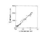
図6は予め計測した光ファイバ歪み値変化量(με)とひび割れ幅変化量(mm)との関係の一例をグラフで示し、図7は計測データの一部を数値で示したものである。なお、図6中の直線は、上記計測データを直線近似したものである。上記図6、図7に示すような計測値を演算処理装置7のCPU21に入力し、このCPU21で例えば計測値から光ファイバ歪み値変化量(με)とひび割れ幅変化量(mm)との関係を例えば直線近似した変換テーブルを作成し、記憶装置23に歪/幅テーブル27として記憶する。この結果、ひび割れ幅変化量をy、光ファイバ歪み値変化量をXとすると、ひび割れ幅変化量yは、
y=aX
の式で求めることが可能となる。なお、上式における「a」は、ひび割れ幅変化量と光ファイバ歪み値変化量との関係を示す係数である。
FIG. 6 is a graph showing an example of the relationship between the previously measured optical fiber strain value change amount (με) and the crack width change amount (mm), and FIG. 7 shows a part of the measured data by numerical values. The straight line in FIG. 6 is obtained by linearly approximating the above measured data. The measured values as shown in FIGS. 6 and 7 are input to the
y = aX
Can be obtained by the following equation. Note that “a” in the above equation is a coefficient indicating the relationship between the amount of change in the crack width and the amount of change in the optical fiber distortion value.
次に上記実施形態における演算処理装置7の動作を図8に示すフローチャートを参照して説明する。
演算処理装置7におけるCPU21は、まず、処理番号N(計測位置を示す)を設定して(ステップA1)、歪み計測器6により各ひび割れ監視区間における光ファイバ2の歪みを計測し(ステップA2)、処理番号に対応した光ファイバ2上の位置XN ,初期歪み値εN0 ,及び初期ひび割れ幅gN0を取得する(ステップA3)。次いで、ひび割れ位置に対応する歪み値εN を取得し(ステップA4)、この歪み値εN から初期歪み値εN0 を減算して歪み変化量ΔεN を取得する(ステップA5)。次に、CPU21は、上記歪み変化量ΔεN を予め歪/幅テーブル27に記憶させておいた「歪とひび割れ幅との関係」に代入し、ひび割れ幅変化量ΔgN を取得する(ステップA6)。このひび割れ幅変化量ΔgN にひび割れ幅の初期値gN0 を加算して現在のひび割れ幅(推定値)gN を得る(ステップA7)。このひび割れ幅gN を時刻tとの対応を取り、データg(N,t)としてデータメモリ28に保存する(ステップA8)。
Next, the operation of the
First, the
そして、上記ひび割れ幅g(N,t)及びそのひび割れ幅変化率(g(N,t)-g(N,t-1))を基準ひび割れ幅gA ,及び基準ひび割れ幅変化率ΔgA と比較して、基準値以上になるかを評価する(ステップA9)。すなわち、
g(N,t)> gA
g(N,t)-g(N,t-1)> ΔgA
但し、「t−1」は、1回前あるいは一定期間前を意味する。
Then, the crack width g (N, t) and the crack width change rate (g (N, t) -g (N, t-1)) are compared with the standard crack width gA and the standard crack width change rate ΔgA. Then, it is evaluated whether it is equal to or more than the reference value (step A9). That is,
g (N, t)> gA
g (N, t) -g (N, t-1)> ΔgA
However, “t−1” means one time before or a certain period before.
の比較処理を行なって、ひび割れ幅g(N,t)が基準値gA 以上であるか、また、そのひび割れ幅変化率が基準ひび割れ幅変化率ΔgA 以上であるかを評価する。 Is evaluated to determine whether the crack width g (N, t) is equal to or greater than the reference value gA and whether the crack width change rate is equal to or greater than the reference crack width change rate ΔgA.
上記の評価を行なった結果、ひび割れ幅g(N,t)及びそのひび割れ幅変化率が基準値以上でなければ、位置を変更、すなわちNの値を変更して上記と同様の処理を実行する(ステップA10)。そして、計測処理を終了した後は、計測結果を表示装置24に表示し、必要に応じて印刷する。
As a result of the above evaluation, if the crack width g (N, t) and the crack width change rate are not equal to or larger than the reference value, the position is changed, that is, the value of N is changed and the same processing as described above is executed. (Step A10). Then, after the measurement processing is completed, the measurement result is displayed on the
また、上記ステップA9で評価を行なった結果、ひび割れ幅g(N,t)及び、ひび割れ幅変化率の一方あるいは両方が基準値以上であった場合は、警報を発すると共に警報を示すメッセージ及び計測値を表示装置24上に表示する(ステップA11)。この場合、更に、危険を示す情報を演算処理装置7から有線あるいは無線等で監視センターに送信するようにしても良い。
If one or both of the crack width g (N, t) and the crack width change rate are equal to or more than the reference values as a result of the evaluation in step A9, an alarm is issued, a message indicating the alarm, and a measurement. The value is displayed on the display device 24 (step A11). In this case, the information indicating the danger may be further transmitted from the
なお、上記歪み計測器6及び演算処理装置7は、光ファイバ2に常時接続しておいても良いが、例えば定期点検の際に光ファイバ2に接続してひび割れ幅を検知するようにしても良い。
The
上記のように歪み計測器6の計測結果を演算処理装置7に入力し、予め計測して歪/幅テーブル27に記憶させておいた歪とひび割れ幅との関係からひび割れ幅を求めることにより、ひび割れ幅を高精度で検知することができる。
As described above, the measurement result of the
(第2実施形態)
次に本発明の第2実施形態について説明する。
この第2実施形態は、図9に示すようにトンネル覆工3の内壁面を例えば繊維シート等の補強材31により補強した場合において、補強材31の剥離を光ファイバ2を利用して検知する場合の例について示したものである。
(2nd Embodiment)
Next, a second embodiment of the present invention will be described.
In the second embodiment, as shown in FIG. 9, when the inner wall surface of the tunnel lining 3 is reinforced by a reinforcing
トンネル覆工3の内壁面を補強材31により補強する際、ひび割れ4の位置を確認しておき、補強終了後、補強材31の表面上に上記ひび割れ4と直交する方向に光ファイバ2を配設し、2点を固定部材5で接着固定する。この場合、光ファイバ2は、ひび割れ4の上に一方の固定端が位置するように例えば直径が60mm程度の固定部材5を用いて接着固定する。上記光ファイバ2の固定部分の間は緩みのない程度の張力をかけ、その固定間隔は光ファイバ2の距離分解能に応じて設定する。光ファイバ2の距離分解能が長い場合には、上記図3に示したように折り返して固定することで固定間隔を短くする。また、上記光ファイバ2は、他の補強部分においても同様にひび割れ4の上に一方の固定端が位置するように固定部材5により固定される。
When reinforcing the inner wall surface of the tunnel lining 3 with the reinforcing
そして、上記光ファイバ2の始端部には、剥離監視位置における光ファイバ2の歪みを計測する歪み計測器6、演算処理装置7が接続され、光ファイバ2の末端には終端処理用ループ(図示せず)が設けられる。
At the start end of the
上記の構成において、トンネル1が変形してひび割れ4の幅が広くなる際、図10に矢印で示すように補強材31に引張り歪みが発生し、それに伴って光ファイバ2に引張り歪みが発生する。この光ファイバ2の引張り歪みは、歪み計測器6にて計測され、その計測値が演算処理装置7に入力される。
In the above configuration, when the tunnel 1 is deformed and the width of the crack 4 is widened, a tensile strain is generated in the reinforcing
その後、トンネル1の変形が進み、ひび割れ4の幅が広くなるに伴って光ファイバ2の引張り歪みが増大し、やがて図11に示すように補強材31がトンネル覆工3の内壁面から剥離する。補強材31がトンネル覆工3の内壁面から剥離すると、剥離開始位置、すなわち、ひび割れ4の位置にある固定部材5が補強材31と一緒に壁面から浮くために光ファイバ2の張力が減少して見かけ上、圧縮歪みが発生する。従って、歪み計測器6により計測された光ファイバ2の歪みを演算処理装置7でメモリに記憶し、常時あるいは予め設定された一定時間毎に前回計測した歪と今回計測した歪とを比較し、引張り歪みから圧縮歪みに変化した位置を検知することにより、補強材31が剥離した位置を検知することができる。
Thereafter, the deformation of the tunnel 1 progresses, and the tensile strain of the
図12は、大型トンネルをモデルとして、補強材31の剥離に伴う光ファイバ2の歪分布の変化状態を示したもので、横軸に光ファイバの位置(mm)をとり、縦軸に光ファイバ歪み(με)をとって示した。図12(a)は、補強材31が剥離する前における光ファイバ2の歪み発生状態を示したもので、ひび割れ4が発生している位置に大きな引張り歪みが発生している。図12(b)は、補強材31が壁面から剥離したときの光ファイバ2の歪み発生状態を示したもので、剥離した位置に大きな圧縮歪みが発生している。
FIG. 12 shows the state of change in the strain distribution of the
上記のように補強材31がトンネル覆工3の内壁面から剥離すると、剥離開始位置にある固定部材5が補強材31と一緒に壁面から浮くために光ファイバ2の張力が減少して見かけ上圧縮歪みが発生するので、引張り歪みから圧縮歪みに変化した位置を演算処理装置7にて検知することにより、補強材31が剥離した位置を確実に検知することができる。また、光ファイバの引張り歪みから圧縮歪みに変化する点を検出するようにしているので、補強材31として導電性のものを使用することなく補強材31の剥離を検出でき、電気設備が設置される鉄道トンネル等においても安全に使用することができる。
When the reinforcing
上記演算処理装置7の検知結果は、第1実施形態と同様に表示装置に表示し、必要に応じて印刷する。また、演算処理装置7が補強材31の剥離を検知した場合、警報を発すると共に、補強材31が剥離した位置情報を表示装置24に表示する。この場合、更に、上記補強材31が剥離したことを示す危険情報を演算処理装置7から有線あるいは無線等で監視センターに送信するようにしても良い。
The detection result of the
なお、上記歪み計測器6及び演算処理装置7は、光ファイバ2に常時接続しておいても良いが、例えば定期点検の際に光ファイバ2に接続して補強材31の剥離を検知するようにしても良い。
The
1…トンネル、2…光ファイバ、3…トンネル覆工、4…ひび割れ、5…固定部材、6…歪み計測器、7…演算処理装置、10…歪み分布測定器、11…光源、12…光周波数シフタ、13…被測定光ファイバ、14…検波器、21…CPU、22…入力装置、23…記憶装置、24…表示装置、25…初期歪み用メモリ、26…初期ひび割れ幅用メモリ、27…歪/幅テーブル、28…データメモリ、31…補強材。
DESCRIPTION OF SYMBOLS 1 ... Tunnel, 2 ... Optical fiber, 3 ... Tunnel lining, 4 ... Cracking, 5 ... Fixing member, 6 ... Strain measuring device, 7 ... Processing device, 10 ... Strain distribution measuring device, 11 ... Light source, 12 ...
Claims (3)
前記トンネル内面の補強材の表面に光ファイバを張力をかけながらひび割れの上に一方の固定端が位置するように固定すると共に、剥離監視位置における光ファイバの歪みを歪み計測器で計測し、前記剥離監視位置の歪みが引張り歪みから圧縮歪みに変化した状態を検出して補強材の剥離を検知することを特徴とするトンネル補強材剥離検知方法。 An optical fiber is fixed to the surface of a reinforcing material that reinforces a wall surface in a tunnel, and in a tunnel reinforcing material peeling detection method for detecting the peeling of the reinforcing material by measuring the relationship between the strain and the position of the optical fiber,
Affixing the optical fiber to the surface of the reinforcing material on the inner surface of the tunnel so that one fixed end is located on the crack while applying tension, and measuring the strain of the optical fiber at the peel monitoring position with a strain measuring instrument, A method for detecting peeling of a tunnel reinforcing material, comprising detecting a state in which a strain at a peel monitoring position changes from a tensile strain to a compressive strain to detect peeling of a reinforcing material.
前記トンネル内面の補強材の表面に光ファイバを張力をかけながらひび割れの上に一方の固定端が位置するように固定する固定手段と、剥離監視位置における光ファイバの歪みを計測する歪み計測器と、この歪み計測器により計測された歪みを記憶する記憶手段と、前記歪み計測器により今回計測された歪と前記記憶手段に記憶された前回計測時の歪みとを比較し、計測された歪が引張り歪みから圧縮歪みに変化した状態を検出して補強材の剥離を検知する手段とを具備したことを特徴とするトンネル補強材剥離検知装置。 An optical fiber is fixed to a surface of a reinforcing material that reinforces a wall surface in a tunnel, and a tunnel reinforcing material peeling detection device that detects a peeling of the reinforcing material by measuring a relationship between a strain and a position of the optical fiber,
A fixing means for fixing the optical fiber on the surface of the reinforcing material on the inner surface of the tunnel so that one fixed end is located on the crack while applying tension, and a strain measuring instrument for measuring the strain of the optical fiber at the peeling monitoring position. A storage means for storing the strain measured by the strain measuring instrument, and comparing the strain measured this time by the strain measuring instrument with the strain at the previous measurement stored in the storage means, and A means for detecting a state in which the tensile strain has changed from a compressive strain to a compressive strain and detecting peeling of the reinforcing material.
Priority Applications (1)
| Application Number | Priority Date | Filing Date | Title |
|---|---|---|---|
| JP2004003059A JP3759144B2 (en) | 2004-01-08 | 2004-01-08 | Tunnel reinforcing material peeling detection method and apparatus |
Applications Claiming Priority (1)
| Application Number | Priority Date | Filing Date | Title |
|---|---|---|---|
| JP2004003059A JP3759144B2 (en) | 2004-01-08 | 2004-01-08 | Tunnel reinforcing material peeling detection method and apparatus |
Related Parent Applications (1)
| Application Number | Title | Priority Date | Filing Date |
|---|---|---|---|
| JP24333699A Division JP3534659B2 (en) | 1999-08-30 | 1999-08-30 | Tunnel crack detection method and device |
Publications (2)
| Publication Number | Publication Date |
|---|---|
| JP2004190478A true JP2004190478A (en) | 2004-07-08 |
| JP3759144B2 JP3759144B2 (en) | 2006-03-22 |
Family
ID=32768088
Family Applications (1)
| Application Number | Title | Priority Date | Filing Date |
|---|---|---|---|
| JP2004003059A Expired - Fee Related JP3759144B2 (en) | 2004-01-08 | 2004-01-08 | Tunnel reinforcing material peeling detection method and apparatus |
Country Status (1)
| Country | Link |
|---|---|
| JP (1) | JP3759144B2 (en) |
Cited By (4)
| Publication number | Priority date | Publication date | Assignee | Title |
|---|---|---|---|---|
| KR200449473Y1 (en) | 2009-01-14 | 2010-07-13 | (주)한국해외기술공사 | Safety check-up apparatus in tunnel is easing measurement and confirmation of crack position |
| CN111120005A (en) * | 2019-12-31 | 2020-05-08 | 华中科技大学 | Distributed tunnel reinforcing steel ring failure monitoring device and method |
| KR102393354B1 (en) * | 2021-09-30 | 2022-05-03 | 경북대학교 산학협력단 | Reinforcing material for civil structures provided with light emitting members and civil structures using the same to form reinforcing force |
| WO2023033460A1 (en) * | 2021-08-31 | 2023-03-09 | 경북대학교 산학협력단 | Structure reinforcement material having light-emitting member, and structure having stiffening force formed using same |
Families Citing this family (3)
| Publication number | Priority date | Publication date | Assignee | Title |
|---|---|---|---|---|
| CN104374323B (en) * | 2014-10-30 | 2015-08-12 | 河海大学 | Distributed monitoring device and method inside and outside the micro-macroscopic fracture of hydraulic structures polytropism |
| JP7146192B2 (en) * | 2018-12-04 | 2022-10-04 | 東電設計株式会社 | Method for estimating residual prestress force of PC girder |
| CN109827519B (en) * | 2019-03-14 | 2020-06-02 | 广东聚源管业实业有限公司 | Pipeline deformation monitoring method |
-
2004
- 2004-01-08 JP JP2004003059A patent/JP3759144B2/en not_active Expired - Fee Related
Cited By (4)
| Publication number | Priority date | Publication date | Assignee | Title |
|---|---|---|---|---|
| KR200449473Y1 (en) | 2009-01-14 | 2010-07-13 | (주)한국해외기술공사 | Safety check-up apparatus in tunnel is easing measurement and confirmation of crack position |
| CN111120005A (en) * | 2019-12-31 | 2020-05-08 | 华中科技大学 | Distributed tunnel reinforcing steel ring failure monitoring device and method |
| WO2023033460A1 (en) * | 2021-08-31 | 2023-03-09 | 경북대학교 산학협력단 | Structure reinforcement material having light-emitting member, and structure having stiffening force formed using same |
| KR102393354B1 (en) * | 2021-09-30 | 2022-05-03 | 경북대학교 산학협력단 | Reinforcing material for civil structures provided with light emitting members and civil structures using the same to form reinforcing force |
Also Published As
| Publication number | Publication date |
|---|---|
| JP3759144B2 (en) | 2006-03-22 |
Similar Documents
| Publication | Publication Date | Title |
|---|---|---|
| JP3534659B2 (en) | Tunnel crack detection method and device | |
| US5723857A (en) | Method and apparatus for detecting cracks and strains on structures using optical fibers and Bragg gratings | |
| JP3668199B2 (en) | Tunnel deformation measurement method | |
| KR20200088439A (en) | Wire rope inspection device, wire rope inspection system and wire rope inspection method | |
| EP0845672A1 (en) | Wire rope damage index monitoring device | |
| RU2686839C2 (en) | Device and method for electromechanical cable overvoltage indicator | |
| JP3759144B2 (en) | Tunnel reinforcing material peeling detection method and apparatus | |
| JP3758905B2 (en) | Optical fiber laying method and strain detection apparatus using optical fiber | |
| JP2007113991A (en) | Crack detector and installation method therefor | |
| JP2000046527A (en) | Pc material with strain detection system and method for detecting strain | |
| JP2001194109A (en) | Displacement measuring apparatus using rayleigh scattering | |
| JP2000111339A (en) | Method for laying optical fiber and distortion-detecting device using optical fiber | |
| JPH1172481A (en) | Detector and method for detecting fracture of reinforcing bar | |
| WO2018034062A1 (en) | Management method and management device | |
| JP2008139238A (en) | Optical fiber sensor cable | |
| KR102197696B1 (en) | Structure health monitoring system using optic fiber-based hybrid nerve network sensor, and method for the same | |
| JP3586611B2 (en) | Strain detection method and strain detection system using optical fiber | |
| JPH11325822A (en) | Crack monitoring equipment | |
| CN105572329B (en) | Concrete crack scale distance adaptive monitoring method | |
| JP2000097647A (en) | Method for measuring deformation of structure using optical fiber and optical fiber sensor | |
| JP2008014641A (en) | Optical fiber sensor, and distortion measuring method using the same | |
| CN210177368U (en) | Intelligent inhaul cable and fiber reinforced optical fiber lacing wire | |
| JP2010112942A (en) | Method for monitoring of steel structure | |
| JP6554065B2 (en) | Method and system for evaluating deterioration state of metal structure | |
| JP2017211266A (en) | Foundation and bedrock distortion measurement device, and foundation and bedrock measurement method |
Legal Events
| Date | Code | Title | Description |
|---|---|---|---|
| TRDD | Decision of grant or rejection written | ||
| A01 | Written decision to grant a patent or to grant a registration (utility model) |
Free format text: JAPANESE INTERMEDIATE CODE: A01 Effective date: 20051206 |
|
| A61 | First payment of annual fees (during grant procedure) |
Free format text: JAPANESE INTERMEDIATE CODE: A61 Effective date: 20051227 |
|
| R150 | Certificate of patent or registration of utility model |
Free format text: JAPANESE INTERMEDIATE CODE: R150 |
|
| RD03 | Notification of appointment of power of attorney |
Free format text: JAPANESE INTERMEDIATE CODE: A7423 Effective date: 20060130 |
|
| A521 | Written amendment |
Free format text: JAPANESE INTERMEDIATE CODE: A821 Effective date: 20060130 |
|
| A072 | Dismissal of procedure |
Free format text: JAPANESE INTERMEDIATE CODE: A072 Effective date: 20060613 |
|
| FPAY | Renewal fee payment (event date is renewal date of database) |
Free format text: PAYMENT UNTIL: 20100113 Year of fee payment: 4 |
|
| FPAY | Renewal fee payment (event date is renewal date of database) |
Free format text: PAYMENT UNTIL: 20100113 Year of fee payment: 4 |
|
| FPAY | Renewal fee payment (event date is renewal date of database) |
Free format text: PAYMENT UNTIL: 20110113 Year of fee payment: 5 |
|
| S111 | Request for change of ownership or part of ownership |
Free format text: JAPANESE INTERMEDIATE CODE: R313117 |
|
| FPAY | Renewal fee payment (event date is renewal date of database) |
Free format text: PAYMENT UNTIL: 20110113 Year of fee payment: 5 |
|
| R350 | Written notification of registration of transfer |
Free format text: JAPANESE INTERMEDIATE CODE: R350 |
|
| FPAY | Renewal fee payment (event date is renewal date of database) |
Free format text: PAYMENT UNTIL: 20110113 Year of fee payment: 5 |
|
| FPAY | Renewal fee payment (event date is renewal date of database) |
Free format text: PAYMENT UNTIL: 20120113 Year of fee payment: 6 |
|
| S533 | Written request for registration of change of name |
Free format text: JAPANESE INTERMEDIATE CODE: R313533 |
|
| FPAY | Renewal fee payment (event date is renewal date of database) |
Free format text: PAYMENT UNTIL: 20120113 Year of fee payment: 6 |
|
| R350 | Written notification of registration of transfer |
Free format text: JAPANESE INTERMEDIATE CODE: R350 |
|
| FPAY | Renewal fee payment (event date is renewal date of database) |
Free format text: PAYMENT UNTIL: 20130113 Year of fee payment: 7 |
|
| LAPS | Cancellation because of no payment of annual fees |