JP2004190404A - Reinforcing cage for cast-in-place concrete pile - Google Patents
Reinforcing cage for cast-in-place concrete pile Download PDFInfo
- Publication number
- JP2004190404A JP2004190404A JP2002361583A JP2002361583A JP2004190404A JP 2004190404 A JP2004190404 A JP 2004190404A JP 2002361583 A JP2002361583 A JP 2002361583A JP 2002361583 A JP2002361583 A JP 2002361583A JP 2004190404 A JP2004190404 A JP 2004190404A
- Authority
- JP
- Japan
- Prior art keywords
- pile
- reinforcing
- pile main
- bar
- cast
- Prior art date
- Legal status (The legal status is an assumption and is not a legal conclusion. Google has not performed a legal analysis and makes no representation as to the accuracy of the status listed.)
- Granted
Links
Images


Abstract
Description
【0001】
【発明の属する技術分野】
本発明は、場所打ちコンクリート杭工法に使用する鉄筋かごに関する。
【0002】
【従来の技術】
建物等の構築物の基礎杭を設ける工法として、場所打ちコンクリート杭工法が知られている。かかる工法では、アースドリル等の掘孔機を用いて、地盤直下、鉛直方向に向けて杭孔を掘削する。掘削は、掘削端が基礎杭上に設けられる建物等の構築物の荷重を十分に支持できる堅固な支持層に至るまで行う。
【0003】
かかる杭孔内には、杭孔の深さにほぼ匹敵する長さの略円筒状に鉄筋等を組み合わせた鉄筋かごが挿入される。その後、杭孔内にはコンクリートが打設され、鉄筋コンクリート製の基礎杭が構築される。
【0004】
かかる場所打ちコンクリート杭工法で用いられる鉄筋かごは、一般的には、図6(A)、(B)に示すような構成を有している。すなわち、鉄筋かご1は、例えば、厚さ約9mm、幅約75mmの平鋼を円形の帯状に加工した補強リング2を所定間隔で配設し、その補強リング2の周囲に複数本の杭主筋3を所定間隔離して平行に添わせ、補強リング2と杭主筋3とを溶接固定することによりかご状に形成されている。杭主筋3の外側には、リング状のフープ筋4が回されている。
【0005】
図6に示すように、鉄筋かご1は、略円形、筒状に形成されており、通常、鉄筋かご1基当たり、補強リング2は3箇所以上設けられている。
【0006】
鉄筋かご1に設ける複数の補強リング2の内、最上段に設ける第1補強リング2a(2)は、鉄筋かご1の最上部より、すなわち杭主筋3の最上端より基礎スラブへの定着長さより少し下がった位置に設けられている。
【0007】
【発明が解決しようとする課題】
本発明者は、上記構成を有する場所打ちコンクリート杭工法に用いられる鉄筋かごにおいて、以下のような技術的問題点があることに気がついた。
【0008】
建築物等の構築物を支持する基礎杭は、地震時には水平力を受けることとなり、杭には曲げ応力(曲げモーメント)が生ずる。かかる応力は、杭の地震時応力(曲げモーメント)に関する図5に模式的に示すように、杭頭部が最大となる。杭に曲げ応力が作用すると、コンクリート杭に埋設されている杭主筋に引張力が生じるが、かかる杭主筋は第1補強リングに溶接固定されているため、上記引張力により、溶接部で脆性的に破断が生じ、コンクリート杭の深刻な強度低下および変形性筋低下が起きる。
【0009】
また、図6に示すような従来構成の鉄筋かご1では、第1補強リング2a(2)より上方にでている杭主筋部は、杭上に基礎スラブを構築する際の配筋用として、配筋作業がし易いように杭主筋の自由度をある程度確保できるようにそのまま上方に伸長されているだけである。そのため、杭主筋はその上端側が何ら拘束されていないため、外力により曲がりやすかった。かかる曲がり易さが、余盛りコンクリートの斫り取り作業時に大きな影響を及ぼすことに、本発明者は気がついた。
【0010】
場所打ちコンクリート杭工法では、一般的に、掘削した杭孔内にベントナイト溶液もしくはポリマー溶液等の充填液を注入し、その後に前記構成の鉄筋かごを挿入・配設し、鉄筋かごの配設後に、トレミー管等を使用してコンクリートを流し込む方法が採用されている。
【0011】
かかるコンクリート打設の方法では、杭頭部側のコンクリートには泥土が混在するため、杭本来の高さよりも予めコンクリートを余分に打設して杭頭に余盛りコンクリートを形成させ、杭本来のコンクリート部分に泥土の混入が発生しないようにしている。かかる杭頭余盛りコンクリートは、杭施工終了後、定着部の鉄筋を出現させるために、根切作業で切り取られなければならない。
【0012】
しかし、余盛りコンクリートの斫り取り作業は、周囲を杭主筋に囲まれた狭い窮屈な状態で行うため、斫り取り作業時にブレーカーや掘削機等で杭主筋等の鉄筋を引っかけるミスが発生し易い。かかる場合に、杭主筋が前記のように曲がりやすいため、引っかけられた杭主筋が曲がって杭主筋の位置ずれが発生し、基礎杭上に基礎スラブを設ける基礎梁等の配筋時に、かかる杭主筋の位置ずれが原因となり配筋作業が円滑に行えない等の支障が発生している。
【0013】
一方、曲がった杭主筋の曲げ戻しを行うと、場合によっては、鉄筋がもろく破断することもあり、安易な曲げ戻しは行えない。そのため、上記杭頭余盛りコンクリートの斫り取り作業には、杭主筋の鉄筋を引っかけないように十分の注意が必要となる。
【0014】
しかし、余盛りコンクリートは既に硬化しているためその斫り取りには、強い力を掛けて行わなければならず、勢い、十分な注意を払っているにもかかわらず杭主筋を強く引っかけることも起こりやすい。引っかけミスを完全に無くすことは難しい。当初より、かかる杭主筋が曲がり難いようにしておくことが望ましいと、本発明者は考えた。
【0015】
さらに、従来構成の鉄筋かごでは、鉄筋かごの吊り上げに際しては、基礎スラブ側への定着を行う第1補強リングに、フック等を掛けるようにして行うため、場合によっては、フックを掛ける際に杭主筋、あるいは補強リングに強くフック等をぶつける等して変形を生じさせる場合もあった。かかる基礎スラブに定着させる補強リング部は、基礎杭施工後には基礎梁との配筋を行うための杭主筋の位置精度を維持している箇所でもあり、かかる箇所の変形等は極力避けなければならない。
【0016】
本発明の目的は、地震時などで水平力が場所打ちコンクリート杭に作用しても、杭主筋と補強リングとの溶接部の破断が生じないようにすることにある。
【0017】
別の本発明の目的は、場所打ちコンクリート杭工法において、杭頭上方側に伸びている杭主筋を曲がり難いようにすることにある。
【0018】
【課題を解決するための手段】
本発明は、場所打ちコンクリート杭工法に使用される鉄筋かごであって、前記鉄筋かごは、補強リングと、杭主筋と、フープ筋とを有し、前記鉄筋かごを前記杭孔内に配設した状態で、前記杭主筋は、第1補強リングより上方側に伸びている部分が、杭主筋拘束部材により前記杭主筋の位置変動が拘束されていることを特徴とする。
【0019】
本発明は、場所打ちコンクリート杭工法に使用される鉄筋かごであって、前記鉄筋かごは、杭主筋と、フープ筋と、補強リングとを有し、第1補強リングは、前記杭主筋と線結束されていることを特徴とする。
【0020】
かかる構成において、前記鉄筋かごを前記杭孔内に配設した状態で、前記杭主筋と線結束されている第1補強リングより上方側に伸びている杭主筋伸出部分には、前記杭主筋の位置変動を拘束する杭主筋拘束部材が設けられていることを特徴とする。
【0021】
上記いずれかの構成において、前記杭主筋拘束部材はリング状に形成され、前記杭主筋伸出部分の上端側と固着されていることを特徴とする。前記第1補強リングは、鉄筋で形成するようにしてもよい。
【0022】
ここで「第1補強リング」とは、鉄筋かごを杭孔内に配設した状態で、杭頭部に最も近接した位置に設けられ、場所打ちコンクリート施工完了後には、コンクリート内に埋設されていることとなる補強リングを意味するものとする。
【0023】
以上の構成を有する本発明の鉄筋かごでは、地震時等に受ける水平力に対して杭の応力が最大となる部分では、従来構成の鉄筋かごとは異なり、第1補強リングと杭主筋とが溶接固定されていないため、杭主筋が引張力を受けても脆性破断は発生せず、杭主筋の母材の強度および変形性筋としての機能をフルに発揮することができる。
【0024】
また、前記の如く、杭主筋伸出部分を杭主筋拘束部材により拘束して固定することにより、杭頭側にそのまま伸ばしていた杭主筋を曲がりにくくすることができる。そのため、例えば、杭施工終了後、土を掘削して定着部の鉄筋を出現させるに際して、掘削機等を鉄筋に多少引っかけても杭主筋の変形を生じにくくさせ、杭主筋の位置ずれを抑制して、その後の基礎梁等との配筋作業を円滑に行わせることができる。
【0025】
したがって、従来程には、杭主筋の引っかけミスに神経を使わずに根切作業、余盛りコンクリートの斫り取り作業が行え、かかる作業の円滑化、効率化を図ることができる。
【0026】
尚、鉄筋かごの最上部は、すなわち杭主筋伸出部分の上端側は、第1補強リングより上方に位置しているため、上記水平力に対して引張力を受けない箇所で、杭主筋拘束部材と杭主筋とを溶接する等して杭主筋伸出部の位置固定を行っても脆性破断等の虞はなく、杭主筋の位置変動をこのように拘束することに技術的な支障はない。
【0027】
【発明の実施の形態】
以下、本発明の実施の形態を図面に基づいて詳細に説明する。
【0028】
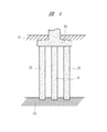
図1(A)は、本発明の鉄筋かごを、杭孔内に配設する立設状態の姿勢で示す正面図であり、(B)は(A)の鉄筋かごを上方からみた様子を示す平面図である。
【0029】
鉄筋かご10は、図1(A)、(B)に示すように、上下方向に沿って所定間隔に設けた複数の補強リング11(11a、11b、11c、11d)に、鉄筋で構成された杭主筋12が交わるように設けられて形成されている。
【0030】
補強リング11は、所定厚の平鋼をリング状に形成して構成され、図1(B)に示すように、かかる補強リング11の外周面に、所定間隔で上下方向に通した杭主筋12が複数本設けられている。
【0031】
複数の補強リング11の内、最上段に設けた第1補強リング11aは、杭頭部側に設けられている。すなわち杭主筋12の最上端より基礎スラブへの定着長さより少し下がった位置に設けられている。他の補強リング11b、11c、11dは、例えば、第1補強リング11aと鉄筋かご10の底部側との間を等分した位置に設けておけばよい。
【0032】
因みに、図1(A)に示す鉄筋かご10では、全長aは、杭主筋12の基礎スラブへの定着に用いる定着長bと、余長cとを含めて、10mの高さに構成した場合を例示している。
【0033】
補強リング11に杭主筋12を設けるには、第1補強リング11aと杭主筋12とは、鉄線等の線材を使用した線結束により設けられている。一方、補強リング11b、11c、11dに対しては、杭主筋12は溶接にて固着されている。
【0034】
従来構成では、図6に示すように、補強リング2と杭主筋3とは、全て溶接固着されているが、本発明では、基礎スラブに定着する第1補強リング11aと杭主筋12とは溶接固着によらず、線結束で結ばれている。
【0035】
溶接固着する従来構成では、前述の如く、地震時等における水平力を受ける状態では、杭頭部に発生する大きな曲げモーメントにより、第1補強リング2aと杭主筋3との溶接固着部は脆性破断させられるが、本発明では、上記のように線結束させられているので、溶接固着とは異なり、線結束部では杭主筋12に溶接による欠陥が生じないために脆性破壊には至らない。
【0036】
線結束に使用する線材としては、鉄線等の金属線が使用できるが、第1補強リング11aに杭主筋12を設けるに必要な結束力であれば、金属線以外の線材を用いても一向に構わない。
【0037】
さらには、上記説明では、線結束により第1補強リング11aに杭主筋12を設ける構成を採用したが、かかる線結束以外の手段でも、上記水平力に基づく大きな曲げモーメントが発生しても杭主筋の脆性破壊に至らない手段であれば、第1補強リング11aと杭主筋12とを設ける手段として採用しても構わない。
【0038】
すなわち、基礎スラブに定着させる補強リングと杭主筋とを溶接固着したと想定した場合に、第1補強リングを前記杭主筋に取り付ける時に杭主筋に有害な欠陥を生じない取付け手段であれば、上記線結束手段以外の手段でも採用することができる。
【0039】
また、上記説明では、第1補強リング11aは、平鋼をリング状に形成して構成されているが、平鋼では幅があるため鉄線等による線結束が行い難い場合も想定される。そこで、かかる線結束がし易いように、第1補強リング11aには、例えば、平鋼ではなく鉄筋をリング状に形成したものを使用しても構わない。
【0040】
このようにして第1補強リング11aをも含めて補強リング11に交設するようにして設けた杭主筋12の周囲には、フープ筋13が、上下方向に所定間隔で複数設けられている。
【0041】
尚、図1では、第1補強リング11a(11)は、分かりやすいように、黒く塗り潰して表示した。
【0042】
また、フープ筋13には、図2に示すように、スペーサ13aが設けられている。スペーサ13aは、例えば、帯状の平鋼の中央部が略台形等の凸状に形成され、両端側を上下のフープ筋13に溶接固定して設けられている。
【0043】
かかる構成を採用すれば、杭主筋に溶接によりスペーサを取り付ける従来構成とは異なり、杭主筋に引張力がかかった場合でも溶接部の脆性破断を生じさせることがない。尚、図が見やすいように、スペーサ13aは、図2以外ではその図示を省略している。
【0044】
第1補強リング11aより上方に伸ばした杭主筋12部分、すなわち杭主筋伸出部分12aには、図1(A)に示すように、杭主筋拘束部材14が設けられている。杭主筋拘束部材14は、例えば、平鋼あるいは鉄筋を用いたリングに形成しておけばよい。
【0045】
柱主筋拘束部材14のリング外周に、杭主筋12の上記杭主筋伸出部分12aが固着手段で設けられている。図1(A)に示す場合には、杭主筋伸出部分12aの上端側、すなわち杭主筋12の上端側が、溶接により杭主筋拘束部材14に固着されている。
【0046】
杭主筋拘束部材14に杭主筋12の上端側が固着されているため、かかる固着が施されていない場合に比べて、杭主筋伸出部分12aの曲がりが発生しにくい。すなわち、杭施工終了後の余盛りコンクリートの斫り取り作業時に、誤って杭主筋12を掘削機等で引っかけても、杭主筋12の曲がりが発生しにくく、前述の問題となっていた基礎スラブ施工に関わる配筋時の支障が発生しにくい。
【0047】
図6に示す従来構成の鉄筋かご1では、第1補強リング2a(2)より上方部分では、単に杭主筋12が伸ばされた状態であったが、図1に示すように本発明の鉄筋かご10では、杭主筋拘束部材14により杭主筋の位置が拘束されているため、多少の外力が作用しても杭主筋12は変形しにくく、曲がりにくくなっている。
【0048】
すなわち、杭主筋拘束部材14は、杭主筋12の頭部側にリング状に定着させて杭主筋12を拘束することにより、杭施工終了後の余盛りコンクリートの斫り取り作業時等における曲がり等が発生しないように補強する役目を果たすものである。
【0049】
かかる杭主筋拘束部材14の設置位置は、図1(A)に示す場合には、杭主筋12の上端側に設置した場合を示したが、杭主筋12の曲がりが上記のように効果的に抑止できる範囲内であれば、図示した上端より少し下がった位置に設けるようにしても一向に構わない。
【0050】
さらには、図1(A)に示す場合には、杭主筋拘束部材14を1個設けた場合を示しているが、例えば、上下に所定間隔離して複数個設けても一向に構わない。
【0051】
上記説明のように構成された本発明の鉄筋かご10は、図3(A)〜(E)に示すようにして場所打ちコンクリート杭工法に使用される。
【0052】
基礎杭の構築場所の地盤Gに、図3(A)に示すように、アースドリル等の掘孔機を用いて杭孔20を掘削する。掘削に際しては、少し掘削した時点で、側壁の崩れを防止するためパイプ状のケーシング21を地上側から所定深度まで差し込む。差し込んだ状態で、さらに掘削を進める。掘削と共に、ベントナイト溶液またはポリマー溶液等の充填液22を掘削孔内に満たすように注入して行く。
【0053】
このようにして十分な硬さの支持層G1に至るまで掘削を進め、杭孔20を形成する。掘削した杭孔20内に、図3(B)に示すように、本発明の鉄筋かご10をクレーン等で吊り下げながら挿入し、第1補強リング11aの位置が、基礎スラブ30(図4参照)の設計位置の深度に合うように高さ位置を調節しながら配設する。
【0054】
鉄筋かご10の吊り下げに際しては、本発明の鉄筋かご10では、第1補強リング11aの上方に杭主筋拘束部材14が設けられているので、かかる杭主筋拘束部材14にクレーンのフック等を掛けて吊り下げるようにすればよい。従来のように、第1補強リング11a側をフックに引っかけることがないため、万が一にも、第1補強リング11a側、あるいはその周囲の杭主筋12を曲げたりする等の損傷を与える心配がない。
【0055】
このようにして杭孔20内に鉄筋かご10を配設した状態で、図3(C)に示すように、地上側からトレミー管23を杭孔内底部側に差込み、コンクリートを流し込む。トレミー管23を上方に引き揚げながらコンクリート24を杭孔内底部から上方に充填してゆく。併せて充填液22を排出する。
【0056】
コンクリート24は、基礎スラブ30に定着させる第1補強リング11aよりさらに余分に打設して、図3(D)に示すように、余盛りコンクリート24a(24)を形成しておく。この時点で、ケーシング21は外しておく。打設したコンクリート24が硬化した時点で、すなわち杭施工が完了した時点で、図3(E)に示すように、根切作業を行う。根切作業に伴い、余盛りコンクリート24aを斫り取り除去する。
【0057】
かかる根切時の余盛りコンクリート24aの斫り取り作業では、誤って掘削機等で杭主筋12を引っかけても、杭主筋12は杭主筋拘束部材14により拘束されているため、簡単には曲げ等が発生しない。そのため、杭主筋拘束部材14に相当する構成を有していない従来構成の鉄筋かご1(図6参照)を使用する場合とは異なり、杭主筋12の曲げをそれ程には心配することなく、余盛りコンクリート24aの除去、根切作業を円滑に、従来の場合よりも短時間で行うことができる。
【0058】
根切作業と併せて、図示はしないが、杭孔20内の周囲の地盤Gを第1補強リング11aレベルの上、約300mmの位置まで掘削し、基礎スラブ30の施工域を形成し、基礎スラブ30の基礎梁と鉄筋かご10との配筋を行う。かかる配筋に際して、杭主筋拘束部材14が作業の邪魔になるようであれば、必要に応じて杭主筋拘束部材14は切断して除去してもよい。
【0059】
このようにして基礎杭25を形成し、図4に示すように、基礎杭25上に建物等の構築物の基礎となる基礎スラブ30を設ければよい。かかる構築物としては、建物等の建築物は勿論、橋脚基礎等の土木構築物をも含めることができる。
【0060】
本発明は、上記実施の形態に限定されるものではなく、その要旨を逸脱しない範囲で必要に応じて変更してもよい。
【0061】
例えば、上記説明では、杭主筋拘束部材14の構成と、第1補強リング11aと杭主筋12とを線結束する構成との両構成を採用した鉄筋かご10を例に挙げて説明したが、そのいずれか一方のみを採用した構成も当然に考えられる。
【0062】
すなわち、余盛りコンクリート時の斫り取り作業における杭主筋12の引っかけによる杭主筋12の曲げに関して、特段考慮する必要が無い場合には、第1補強リング11aと杭主筋12との線結束の構成のみを採用することもできる。
【0063】
また、地震時などの水平力に基づく大きな曲げモーメントに関わる前記説明の杭主筋12の脆性破断に特段の考慮をする必要がない場合には、杭主筋拘束部材14を設ける構成だけの構成を採用しても構わない。
【0064】
【発明の効果】
本発明の鉄筋かごでは、地震時等の水平力に対して杭の応力が最大となる部分に、杭主筋を溶接固着させない構成を採用しているので、杭主筋の脆性破断を生じさせることなく、母材の強度を十分に維持した強度確保が行える。
【0065】
本発明の鉄筋かごでは、第1補強リングより上方の杭主筋部分に、杭主筋の位置を拘束する杭主筋拘束部材を設けているので、杭主筋の曲げ等の変形を抑制することができる。
【0066】
そのため、例えば、杭施工終了後の根切時の余盛りコンクリート除去作業等において、誤って杭主筋を引っかけても杭主筋は曲がりにくくなっているため、かかる杭主筋の曲げ事故に従来構成の場合程には腐心することなく作業を行うことができ、杭施工終了後の根切作業、余盛りコンクリート除去作業をより短い時間で効率的に行うことができる。
【図面の簡単な説明】
【図1】(A)は、本発明の鉄筋かごを、杭孔内に配設する立設状態で示す正面図であり、(B)は(A)の鉄筋かごを上方からみた様子を示す平面図である。
【図2】本発明の鉄筋かごにおけるスペーサの取付け状況を示す部分正面図である。
【図3】(A)〜(E)は、本発明の鉄筋かごを用いた場所打ちコンクリート杭工法の主な作業工程を示す断面説明図である。
【図4】場所打ちコンクリート杭工法により形成された基礎杭上に基礎スラブを設けた様子を示す説明図である。
【図5】基礎杭の地震時の応力の作用状況を示す説明図である。
【図6】(A)は、従来構成の鉄筋かごを、杭孔内に配設する立設状態で示す正面図であり、(B)は(A)の鉄筋かごを上方からみた様子を示す平面図である。
【符号の説明】
1 鉄筋かご
2 補強リング
3 杭主筋
4 フープ筋
10 鉄筋かご
11 補強リング
11a 第1補強リング
12 杭主筋
13 フープ筋
14 杭主筋拘束部材
20 杭孔
21 ケーシング
22 充填液
23 トレミー管
24 コンクリート
24a 余盛りコンクリート
25 基礎杭
30 基礎スラブ
a 全長
b 定着長
c 余長
G 地盤
G1 支持層[0001]
TECHNICAL FIELD OF THE INVENTION
The present invention relates to a reinforcing cage used for a cast-in-place concrete pile method.
[0002]
[Prior art]
2. Description of the Related Art Cast-in-place concrete pile method is known as a method of providing a foundation pile for a structure such as a building. In such a construction method, a pile hole is excavated directly below the ground and in a vertical direction using a drilling machine such as an earth drill. The excavation is performed until the excavation end reaches a solid support layer capable of sufficiently supporting the load of a building or the like provided on the foundation pile.
[0003]
Into such a pile hole, a rebar cage in which a rebar or the like is combined in a substantially cylindrical shape having a length substantially equivalent to the depth of the pile hole is inserted. After that, concrete is poured into the pile hole, and a reinforced concrete foundation pile is constructed.
[0004]
The reinforcing cage used in the cast-in-place concrete pile method generally has a configuration as shown in FIGS. 6 (A) and 6 (B). That is, the reinforcing
[0005]
As shown in FIG. 6, the
[0006]
The first reinforcing
[0007]
[Problems to be solved by the invention]
The present inventor has noticed that the following technical problems exist in the reinforced cage used in the cast-in-place concrete pile method having the above configuration.
[0008]
A foundation pile supporting a building such as a building receives horizontal force during an earthquake, and a bending stress (bending moment) is generated in the pile. Such a stress is maximized at the pile head as schematically shown in FIG. 5 relating to the stress (bending moment) of the pile during an earthquake. When a bending stress acts on the pile, a tensile force is generated in the pile reinforcement buried in the concrete pile. However, since the pile reinforcement is welded and fixed to the first reinforcing ring, the pile is brittle at the weld due to the tensile force. The concrete piles break, causing a serious decrease in the strength and deformability of concrete piles.
[0009]
In the
[0010]
In the cast-in-place concrete pile method, generally, a filling solution such as a bentonite solution or a polymer solution is injected into the excavated pile hole, and then the reinforcing cage having the above configuration is inserted and arranged. And a method of pouring concrete by using a tremy tube or the like.
[0011]
In this concrete casting method, since mud is mixed in the concrete on the pile head side, excess concrete is poured in advance from the pile's original height to form extra concrete on the pile head, and the pile's original Mud is not mixed into the concrete part. After the pile construction is completed, the pile head extra concrete must be cut off by root cutting work in order to make the reinforcing bar appear.
[0012]
However, since the surplus concrete shaving work is performed in a narrow and cramped state surrounded by the pile main bar, there is a possibility that a breaker or an excavator will catch the reinforcing bar such as the main bar of the pile during the cutting operation. easy. In such a case, since the main bar of the pile is easily bent as described above, the main bar of the pile that is hooked is bent, causing a displacement of the main bar of the pile. Displacement of the main muscle causes troubles such as difficulty in performing the arrangement work.
[0013]
On the other hand, if the bent main reinforcement of the pile is bent back, the reinforcing steel bar may be fragile and broken in some cases, so that easy bending return cannot be performed. Therefore, in the work of shaving off the pile head excess concrete, sufficient care must be taken so as not to catch the reinforcing bar of the pile main bar.
[0014]
However, since the excess concrete is already hardened, it must be cut off with strong force, and even though it is vigorously and with sufficient caution, the pile main bar may be strongly caught. Easy to happen. It is difficult to completely eliminate hooking mistakes. From the beginning, the present inventor considered that it is desirable to keep such a pile main bar hard to bend.
[0015]
Furthermore, in the conventional reinforcing cage, when the reinforcing cage is lifted, a hook or the like is hooked on the first reinforcing ring for anchoring to the foundation slab side. In some cases, the main bars or the reinforcing ring may be deformed by strongly hitting a hook or the like. The reinforcement ring part to be anchored to such a foundation slab is also a place that maintains the position accuracy of the pile main reinforcement for arranging reinforcement with the foundation beam after foundation pile construction, and deformation of such places must be avoided as much as possible No.
[0016]
An object of the present invention is to prevent a fracture of a welded portion between a main reinforcement of a pile and a reinforcing ring even when a horizontal force acts on a cast-in-place concrete pile during an earthquake or the like.
[0017]
Another object of the present invention is to make it difficult for a pile main bar extending above a pile head to be bent in a cast-in-place concrete pile method.
[0018]
[Means for Solving the Problems]
The present invention relates to a reinforced car used in a cast-in-place concrete pile method, wherein the reinforced car has a reinforcing ring, a pile main reinforcing bar, and a hoop reinforcing bar, and the reinforced car is disposed in the pile hole. In this state, a portion of the pile main reinforcement extending upward from the first reinforcing ring is characterized in that a position change of the pile main reinforcement is restricted by a pile main reinforcement restricting member.
[0019]
The present invention relates to a reinforcing steel cage used in a cast-in-place concrete pile method, wherein the reinforcing steel cage has a pile reinforcing bar, a hoop reinforcing bar, and a reinforcing ring, and a first reinforcing ring is connected to the pile reinforcing bar and a wire. It is characterized by being united.
[0020]
In such a configuration, in a state where the reinforcing cage is arranged in the pile hole, the pile main reinforcement extending portion extending upward from the first reinforcement ring wire-bound to the pile main reinforcement is provided with the pile main reinforcement. Characterized in that a pile main bar restraint member for restraining the position variation of the pile is provided.
[0021]
In any one of the above structures, the pile main bar restraining member is formed in a ring shape, and is fixed to an upper end side of the pile main bar extension. The first reinforcing ring may be formed of a reinforcing bar.
[0022]
Here, the "first reinforcing ring" is provided at a position closest to the pile head in a state where the reinforcing steel cage is arranged in the pile hole, and is buried in the concrete after completion of the cast-in-place concrete. Means the reinforcing ring that will be used.
[0023]
In the rebar cage of the present invention having the above configuration, in the portion where the pile stress is maximum with respect to the horizontal force received during an earthquake or the like, the rebar cage of the conventional configuration is different, and the first reinforcing ring and the pile reinforcement are Since the pile main bar is not fixed by welding, brittle fracture does not occur even if the pile main bar receives a tensile force, and the pile main bar can fully exhibit its strength as a base material and function as a deformable bar.
[0024]
In addition, as described above, the main portion of the pile main bar extension is restrained and fixed by the pile main bar restraining member, so that the main bar of the pile that has been directly extended to the pile head side can be hardly bent. Therefore, for example, after completion of pile construction, when excavating soil to make reinforcing bars appear, the deformation of the main bars of the pile is less likely to occur even when the excavator or the like is slightly hooked on the reinforcing bars, and the displacement of the main bars of the pile is suppressed. Thus, the subsequent reinforcing work with the foundation beams and the like can be performed smoothly.
[0025]
Therefore, rooting work and extra concrete shaving work can be performed without using nerves for the mistake of hooking the main bar of the pile, so that such work can be performed more smoothly and more efficiently.
[0026]
Since the uppermost part of the reinforcing bar, that is, the upper end side of the pile main bar extension portion is located above the first reinforcement ring, the pile main bar restraint is performed at a position where it is not subjected to a tensile force against the horizontal force. There is no danger of brittle fracture, etc., even if the position of the extension of the main reinforcement of the pile is fixed by welding the member and the main reinforcement of the pile, etc., and there is no technical hindrance in restricting the position fluctuation of the main reinforcement of the pile in this way. .
[0027]
BEST MODE FOR CARRYING OUT THE INVENTION
Hereinafter, embodiments of the present invention will be described in detail with reference to the drawings.
[0028]
FIG. 1 (A) is a front view showing the reinforcing cage of the present invention in a standing state in which the reinforcing cage is disposed in a pile hole, and FIG. 1 (B) shows a state where the reinforcing cage of FIG. 1 (A) is viewed from above. It is a top view.
[0029]
As shown in FIGS. 1A and 1B, the reinforcing
[0030]
The reinforcing
[0031]
Of the plurality of reinforcing
[0032]
Incidentally, in the case of the reinforcing
[0033]
In order to provide the pile
[0034]
In the conventional configuration, as shown in FIG. 6, the
[0035]
In the conventional configuration in which welding is fixed, as described above, when horizontal force is applied during an earthquake or the like, a large bending moment generated at the pile head causes brittle fracture of the weld fixing portion between the first reinforcing
[0036]
As a wire used for wire binding, a metal wire such as an iron wire can be used, but any wire other than a metal wire may be used as long as the binding force is necessary to provide the
[0037]
Further, in the above description, the configuration in which the pile
[0038]
In other words, assuming that the reinforcing ring fixed to the foundation slab and the pile main reinforcement are welded and fixed, if the first reinforcing ring is attached to the pile main reinforcement, if the mounting means does not cause harmful defects in the pile main reinforcement, Means other than the wire binding means can also be employed.
[0039]
Further, in the above description, the first reinforcing ring 11a is formed by forming a flat bar into a ring shape. However, since the flat bar has a wide width, a case where wire bundling with an iron wire or the like is difficult to be performed is also assumed. Therefore, in order to facilitate such wire binding, the first reinforcing ring 11a may be made of, for example, a ring formed of a reinforcing bar instead of flat steel.
[0040]
A plurality of hoop bars 13 are provided at predetermined intervals in the vertical direction around the pile
[0041]
In FIG. 1, the first reinforcing ring 11a (11) is painted black so as to be easily understood.
[0042]
As shown in FIG. 2, the
[0043]
By adopting such a configuration, unlike the conventional configuration in which the spacer is attached to the pile main reinforcement by welding, even when a tensile force is applied to the pile main reinforcement, brittle fracture of the welded portion does not occur. The
[0044]
As shown in FIG. 1A, a pile main
[0045]
On the outer periphery of the ring of the column main
[0046]
Since the upper end side of the pile
[0047]
In the
[0048]
That is, the pile main
[0049]
In the case shown in FIG. 1A, the installation position of the pile main
[0050]
Further, in the case shown in FIG. 1 (A), a case is shown in which one pile main
[0051]
The reinforcing
[0052]
As shown in FIG. 3 (A), a
[0053]
In this way, excavation is advanced to the support layer G1 having sufficient hardness, and the
[0054]
When suspending the
[0055]
In the state where the reinforcing
[0056]
The concrete 24 is cast more than the first reinforcing ring 11a to be fixed to the
[0057]
In the operation of shaving off the excess concrete 24a at the time of root cutting, even if the pile
[0058]
In conjunction with the root cutting operation, though not shown, the surrounding ground G in the
[0059]
In this manner, the
[0060]
The present invention is not limited to the above-described embodiment, and may be changed as needed without departing from the gist thereof.
[0061]
For example, in the above description, the
[0062]
That is, if it is not necessary to particularly consider the bending of the pile
[0063]
Further, when it is not necessary to particularly consider the brittle rupture of the pile
[0064]
【The invention's effect】
In the reinforced cage of the present invention, the portion where the stress of the pile is maximized against the horizontal force at the time of an earthquake or the like is employed so that the pile main bar is not welded and fixed, so that the brittle fracture of the pile main bar does not occur. In addition, the strength of the base material can be ensured sufficiently.
[0065]
In the rebar cage of the present invention, since the pile main bar restraint member for restricting the position of the pile main bar is provided in the pile main bar portion above the first reinforcing ring, deformation such as bending of the pile main bar can be suppressed.
[0066]
For this reason, for example, in the removal of excess concrete at the time of root cutting after the completion of pile construction, etc., the pile main reinforcement is difficult to bend even if the pile main reinforcement is accidentally hooked. The work can be carried out without much inconvenience, and the root cutting work and the extra concrete removal work after the completion of the pile work can be performed efficiently in a shorter time.
[Brief description of the drawings]
FIG. 1A is a front view showing a reinforcing cage of the present invention in an upright state in which the reinforcing cage is disposed in a pile hole, and FIG. 1B shows a state in which the reinforcing cage of FIG. It is a top view.
FIG. 2 is a partial front view showing a mounting state of a spacer in the reinforcing cage of the present invention.
3 (A) to 3 (E) are cross-sectional explanatory views showing main working steps of a cast-in-place concrete pile method using a reinforcing cage of the present invention.
FIG. 4 is an explanatory diagram showing a state in which a foundation slab is provided on a foundation pile formed by a cast-in-place concrete pile method.
FIG. 5 is an explanatory diagram showing the state of action of stress on a foundation pile during an earthquake.
FIG. 6 (A) is a front view showing a reinforced cage having a conventional configuration in an upright state in which the reinforced cage is disposed in a pile hole, and FIG. 6 (B) shows a state where the reinforced cage of FIG. It is a top view.
[Explanation of symbols]
DESCRIPTION OF
Claims (6)
前記鉄筋かごは、補強リングと、杭主筋と、フープ筋とを有し、
前記鉄筋かごを前記杭孔内に配設した状態で、前記杭主筋は、第1補強リングより上方側に伸びている部分が、杭主筋拘束部材により前記杭主筋の位置変動が拘束されていることを特徴とする場所打ちコンクリート杭用鉄筋かご。A reinforced basket used for the cast-in-place concrete pile method,
The rebar cage has a reinforcing ring, a pile main bar, and a hoop bar,
In the state where the rebar cage is disposed in the pile hole, a portion of the pile main bar extending upward from the first reinforcing ring is restrained by a pile main bar restraint member from a positional change of the pile main bar. Reinforced basket for cast-in-place concrete piles.
前記鉄筋かごは、杭主筋と、フープ筋と、補強リングとを有し、
第1補強リングは、前記杭主筋と線結束されていることを特徴とする場所打ちコンクリート杭用鉄筋かご。A reinforced basket used for the cast-in-place concrete pile method,
The reinforcing bar has a pile main bar, a hoop bar, and a reinforcing ring,
The first reinforcing ring is wire-tied with the pile main reinforcing bar, wherein the reinforcing steel cage for cast-in-place concrete piles is provided.
前記鉄筋かごを前記杭孔内に配設した状態で、前記杭主筋と線結束されている前記第1補強リングより上方側に伸びている杭主筋伸出部分には、前記杭主筋の位置変動を拘束する杭主筋拘束部材が設けられていることを特徴とする場所打ちコンクリート杭用鉄筋かご。The reinforced car for cast-in-place concrete pile according to claim 2,
In a state where the rebar cage is arranged in the pile hole, a position change of the pile main bar is provided at a pile main bar extension portion extending upward from the first reinforcing ring which is linearly bound to the pile main bar. A reinforcing steel cage for cast-in-place concrete piles, comprising a pile main bar restraining member for restraining the pile.
前記杭主筋拘束部材はリング状に形成され、前記杭主筋伸出部分の上端側と固着されていることを特徴とする場所打ちコンクリート杭用鉄筋かご。The steel cage for cast-in-place concrete pile according to claim 2 or 3,
The pile reinforcing bar restraining member is formed in a ring shape, and is fixed to an upper end side of the pile reinforcing bar extending portion.
前記第1補強リングは、鉄筋で形成されていることを特徴とする場所打ちコンクリート杭用鉄筋かご。The reinforced car for cast-in-place concrete pile according to any one of claims 2 to 4,
The first reinforcing ring is formed of a reinforcing bar, wherein the reinforcing cage for a cast-in-place concrete pile is provided.
スペーサは、前記フープ筋に設けられていることを特徴とする場所打ちコンクリート杭用鉄筋かご。The cast-in-place concrete pile reinforcing steel cage according to any one of claims 1 to 5,
A spacer for a cast-in-place concrete pile, wherein the spacer is provided on the hoop.
Priority Applications (1)
| Application Number | Priority Date | Filing Date | Title |
|---|---|---|---|
| JP2002361583A JP4147101B2 (en) | 2002-12-13 | 2002-12-13 | Steel bar for cast-in-place concrete pile |
Applications Claiming Priority (1)
| Application Number | Priority Date | Filing Date | Title |
|---|---|---|---|
| JP2002361583A JP4147101B2 (en) | 2002-12-13 | 2002-12-13 | Steel bar for cast-in-place concrete pile |
Publications (2)
| Publication Number | Publication Date |
|---|---|
| JP2004190404A true JP2004190404A (en) | 2004-07-08 |
| JP4147101B2 JP4147101B2 (en) | 2008-09-10 |
Family
ID=32760253
Family Applications (1)
| Application Number | Title | Priority Date | Filing Date |
|---|---|---|---|
| JP2002361583A Expired - Lifetime JP4147101B2 (en) | 2002-12-13 | 2002-12-13 | Steel bar for cast-in-place concrete pile |
Country Status (1)
| Country | Link |
|---|---|
| JP (1) | JP4147101B2 (en) |
Cited By (9)
| Publication number | Priority date | Publication date | Assignee | Title |
|---|---|---|---|---|
| CN102828505A (en) * | 2012-08-07 | 2012-12-19 | 中建三局第一建设工程有限责任公司 | Tool type fixing frame for prolonging and protecting cast-in-place pile reinforcement cage |
| CN108425360A (en) * | 2018-05-22 | 2018-08-21 | 高柱福 | A kind of anti-corrosion protection pipe of cement of building apertures stake reinforced column |
| CN110130329A (en) * | 2019-04-10 | 2019-08-16 | 江苏景源万河环境科技有限公司 | It is a kind of to be assembled from expansion formula variable diameters steel reinforcement cage and method of administration entirely with constraint jacket structure |
| JP2020105730A (en) * | 2018-12-26 | 2020-07-09 | 祐司 勝本 | Design method of connected reinforcing bar basket |
| CN112431141A (en) * | 2020-12-08 | 2021-03-02 | 施娟丽 | Cast-in-place mould of usefulness is pour to building bridge stand |
| KR20220123896A (en) * | 2021-03-02 | 2022-09-13 | 주신건기(주) | Construction method of cast in place concrete pile |
| CN115233756A (en) * | 2022-08-25 | 2022-10-25 | 中国建筑第八工程局有限公司 | Cast-in-place pile defect treatment construction method |
| CN115387328A (en) * | 2022-07-26 | 2022-11-25 | 河南黄河河务局工程建设中心 | Construction method of beach area cast-in-place pile based on overlong spiral drilling machine |
| JP2022549528A (en) * | 2021-02-22 | 2022-11-25 | 中▲鉄▼九局集▲団▼第四工程有限公司 | Ultra-long and small-diameter borehole pile construction method |
-
2002
- 2002-12-13 JP JP2002361583A patent/JP4147101B2/en not_active Expired - Lifetime
Cited By (13)
| Publication number | Priority date | Publication date | Assignee | Title |
|---|---|---|---|---|
| CN102828505A (en) * | 2012-08-07 | 2012-12-19 | 中建三局第一建设工程有限责任公司 | Tool type fixing frame for prolonging and protecting cast-in-place pile reinforcement cage |
| CN108425360A (en) * | 2018-05-22 | 2018-08-21 | 高柱福 | A kind of anti-corrosion protection pipe of cement of building apertures stake reinforced column |
| JP2020105730A (en) * | 2018-12-26 | 2020-07-09 | 祐司 勝本 | Design method of connected reinforcing bar basket |
| JP7128108B2 (en) | 2018-12-26 | 2022-08-30 | 祐司 勝本 | Design method of interlocking reinforcing bar cage |
| CN110130329A (en) * | 2019-04-10 | 2019-08-16 | 江苏景源万河环境科技有限公司 | It is a kind of to be assembled from expansion formula variable diameters steel reinforcement cage and method of administration entirely with constraint jacket structure |
| CN112431141A (en) * | 2020-12-08 | 2021-03-02 | 施娟丽 | Cast-in-place mould of usefulness is pour to building bridge stand |
| JP2022549528A (en) * | 2021-02-22 | 2022-11-25 | 中▲鉄▼九局集▲団▼第四工程有限公司 | Ultra-long and small-diameter borehole pile construction method |
| JP7266228B2 (en) | 2021-02-22 | 2023-04-28 | 中▲鉄▼九局集▲団▼第四工程有限公司 | Ultra-long and small-diameter borehole pile construction method |
| KR20220123896A (en) * | 2021-03-02 | 2022-09-13 | 주신건기(주) | Construction method of cast in place concrete pile |
| KR102447617B1 (en) * | 2021-03-02 | 2022-09-28 | 주신건기(주) | Construction method of cast in place concrete pile |
| CN115387328A (en) * | 2022-07-26 | 2022-11-25 | 河南黄河河务局工程建设中心 | Construction method of beach area cast-in-place pile based on overlong spiral drilling machine |
| CN115387328B (en) * | 2022-07-26 | 2024-02-13 | 河南黄河河务局工程建设中心 | Beach cast-in-place pile construction method based on ultra-long spiral drilling machine |
| CN115233756A (en) * | 2022-08-25 | 2022-10-25 | 中国建筑第八工程局有限公司 | Cast-in-place pile defect treatment construction method |
Also Published As
| Publication number | Publication date |
|---|---|
| JP4147101B2 (en) | 2008-09-10 |
Similar Documents
| Publication | Publication Date | Title |
|---|---|---|
| JP2837128B2 (en) | Construction method of cast-in-place concrete pile | |
| CN109183812B (en) | Construction method of combined deep foundation pit supporting structure | |
| JP2009167660A (en) | Tower crane foundation structure and method of constructing the same | |
| JP4013182B2 (en) | Self-supporting mountain retaining wall method and self-supporting mountain retaining wall | |
| JP4147101B2 (en) | Steel bar for cast-in-place concrete pile | |
| KR101311803B1 (en) | Slurry wall underpinning construction method using underpinning concrete tube with uneven surface | |
| JP4391292B2 (en) | Reinforcement structure for floating structures | |
| JP5717118B2 (en) | Cast-in-place steel pipe concrete pile | |
| JP2004244955A (en) | Cast-in-place concrete-filled steel pipe pile, construction method for cast-in-place concrete-filled steel pipe pile and foundation structure of structure | |
| KR100638178B1 (en) | Marine structure and construction method thereof | |
| KR101587062B1 (en) | Steel composite underground earth retaining wall structure and it's construction method | |
| JP5480744B2 (en) | Foundation for structure and its construction method | |
| JP6302288B2 (en) | Formwork installation method, formwork and underwater structure | |
| KR102497458B1 (en) | Cip Retaining Reinforcing Structure and Method Constructing the Same | |
| JP5423134B2 (en) | Foundation structure | |
| KR20120122024A (en) | Uniting Method of Temporary earth wall with basement exterior Wall using Couplers and Bolts. | |
| JP7304248B2 (en) | Pile head connection structure and construction method of pile head connection structure | |
| JP3899307B2 (en) | Cast-in-place concrete filled steel pipe pile and method for constructing cast-in-place concrete filled steel pipe pile | |
| JP5406756B2 (en) | Reinforcement structure and reinforcement method of intermediate restraint bars for pier seismic reinforcement | |
| KR101050824B1 (en) | Pier constructing method for expanding using oscillator on brideg expanding of upper part over water | |
| KR101077242B1 (en) | Construction method of basement structure using retaining wall and steel column | |
| WO2015102032A1 (en) | Support post structure for safety fence | |
| JP4502442B2 (en) | Seismic foundation, seismic building, and pile reinforcement method | |
| CN104631878B (en) | Aluminum casting machine well construction method | |
| JPH07259080A (en) | Self-supported sheath wall structure |
Legal Events
| Date | Code | Title | Description |
|---|---|---|---|
| A621 | Written request for application examination |
Free format text: JAPANESE INTERMEDIATE CODE: A621 Effective date: 20051205 |
|
| A977 | Report on retrieval |
Free format text: JAPANESE INTERMEDIATE CODE: A971007 Effective date: 20070905 |
|
| A131 | Notification of reasons for refusal |
Free format text: JAPANESE INTERMEDIATE CODE: A131 Effective date: 20071009 |
|
| A521 | Request for written amendment filed |
Free format text: JAPANESE INTERMEDIATE CODE: A523 Effective date: 20071206 |
|
| A131 | Notification of reasons for refusal |
Free format text: JAPANESE INTERMEDIATE CODE: A131 Effective date: 20080304 |
|
| A521 | Request for written amendment filed |
Free format text: JAPANESE INTERMEDIATE CODE: A523 Effective date: 20080423 |
|
| TRDD | Decision of grant or rejection written | ||
| A01 | Written decision to grant a patent or to grant a registration (utility model) |
Free format text: JAPANESE INTERMEDIATE CODE: A01 Effective date: 20080603 |
|
| A01 | Written decision to grant a patent or to grant a registration (utility model) |
Free format text: JAPANESE INTERMEDIATE CODE: A01 |
|
| A61 | First payment of annual fees (during grant procedure) |
Free format text: JAPANESE INTERMEDIATE CODE: A61 Effective date: 20080623 |
|
| R150 | Certificate of patent or registration of utility model |
Ref document number: 4147101 Country of ref document: JP Free format text: JAPANESE INTERMEDIATE CODE: R150 Free format text: JAPANESE INTERMEDIATE CODE: R150 |
|
| FPAY | Renewal fee payment (event date is renewal date of database) |
Free format text: PAYMENT UNTIL: 20110627 Year of fee payment: 3 |
|
| FPAY | Renewal fee payment (event date is renewal date of database) |
Free format text: PAYMENT UNTIL: 20110627 Year of fee payment: 3 |
|
| FPAY | Renewal fee payment (event date is renewal date of database) |
Free format text: PAYMENT UNTIL: 20120627 Year of fee payment: 4 |
|
| R250 | Receipt of annual fees |
Free format text: JAPANESE INTERMEDIATE CODE: R250 |
|
| FPAY | Renewal fee payment (event date is renewal date of database) |
Free format text: PAYMENT UNTIL: 20120627 Year of fee payment: 4 |
|
| FPAY | Renewal fee payment (event date is renewal date of database) |
Free format text: PAYMENT UNTIL: 20130627 Year of fee payment: 5 |
|
| R250 | Receipt of annual fees |
Free format text: JAPANESE INTERMEDIATE CODE: R250 |
|
| R250 | Receipt of annual fees |
Free format text: JAPANESE INTERMEDIATE CODE: R250 |
|
| R250 | Receipt of annual fees |
Free format text: JAPANESE INTERMEDIATE CODE: R250 |
|
| R250 | Receipt of annual fees |
Free format text: JAPANESE INTERMEDIATE CODE: R250 |
|
| S531 | Written request for registration of change of domicile |
Free format text: JAPANESE INTERMEDIATE CODE: R313531 |
|
| R350 | Written notification of registration of transfer |
Free format text: JAPANESE INTERMEDIATE CODE: R350 |
|
| R250 | Receipt of annual fees |
Free format text: JAPANESE INTERMEDIATE CODE: R250 |
|
| R250 | Receipt of annual fees |
Free format text: JAPANESE INTERMEDIATE CODE: R250 |
|
| R250 | Receipt of annual fees |
Free format text: JAPANESE INTERMEDIATE CODE: R250 |
|
| R250 | Receipt of annual fees |
Free format text: JAPANESE INTERMEDIATE CODE: R250 |
|
| R250 | Receipt of annual fees |
Free format text: JAPANESE INTERMEDIATE CODE: R250 |
|
| R250 | Receipt of annual fees |
Free format text: JAPANESE INTERMEDIATE CODE: R250 |
|
| R250 | Receipt of annual fees |
Free format text: JAPANESE INTERMEDIATE CODE: R250 |
|
| EXPY | Cancellation because of completion of term |