JP2004189489A - Method and device for estimating thickness of sheet stack - Google Patents
Method and device for estimating thickness of sheet stack Download PDFInfo
- Publication number
- JP2004189489A JP2004189489A JP2003406158A JP2003406158A JP2004189489A JP 2004189489 A JP2004189489 A JP 2004189489A JP 2003406158 A JP2003406158 A JP 2003406158A JP 2003406158 A JP2003406158 A JP 2003406158A JP 2004189489 A JP2004189489 A JP 2004189489A
- Authority
- JP
- Japan
- Prior art keywords
- sheet stack
- finishing
- image forming
- sheet
- unit
- Prior art date
- Legal status (The legal status is an assumption and is not a legal conclusion. Google has not performed a legal analysis and makes no representation as to the accuracy of the status listed.)
- Withdrawn
Links
Images


Classifications
-
- B—PERFORMING OPERATIONS; TRANSPORTING
- B65—CONVEYING; PACKING; STORING; HANDLING THIN OR FILAMENTARY MATERIAL
- B65H—HANDLING THIN OR FILAMENTARY MATERIAL, e.g. SHEETS, WEBS, CABLES
- B65H31/00—Pile receivers
- B65H31/26—Auxiliary devices for retaining articles in the pile
-
- B—PERFORMING OPERATIONS; TRANSPORTING
- B42—BOOKBINDING; ALBUMS; FILES; SPECIAL PRINTED MATTER
- B42C—BOOKBINDING
- B42C1/00—Collating or gathering sheets combined with processes for permanently attaching together sheets or signatures or for interposing inserts
- B42C1/12—Machines for both collating or gathering and permanently attaching together the sheets or signatures
- B42C1/125—Sheet sorters combined with binding devices
-
- B—PERFORMING OPERATIONS; TRANSPORTING
- B65—CONVEYING; PACKING; STORING; HANDLING THIN OR FILAMENTARY MATERIAL
- B65H—HANDLING THIN OR FILAMENTARY MATERIAL, e.g. SHEETS, WEBS, CABLES
- B65H43/00—Use of control, checking, or safety devices, e.g. automatic devices comprising an element for sensing a variable
- B65H43/06—Use of control, checking, or safety devices, e.g. automatic devices comprising an element for sensing a variable detecting, or responding to, completion of pile
-
- B—PERFORMING OPERATIONS; TRANSPORTING
- B65—CONVEYING; PACKING; STORING; HANDLING THIN OR FILAMENTARY MATERIAL
- B65H—HANDLING THIN OR FILAMENTARY MATERIAL, e.g. SHEETS, WEBS, CABLES
- B65H43/00—Use of control, checking, or safety devices, e.g. automatic devices comprising an element for sensing a variable
- B65H43/08—Photoelectric devices
-
- B—PERFORMING OPERATIONS; TRANSPORTING
- B65—CONVEYING; PACKING; STORING; HANDLING THIN OR FILAMENTARY MATERIAL
- B65H—HANDLING THIN OR FILAMENTARY MATERIAL, e.g. SHEETS, WEBS, CABLES
- B65H2511/00—Dimensions; Position; Numbers; Identification; Occurrences
- B65H2511/10—Size; Dimensions
- B65H2511/13—Thickness
-
- B—PERFORMING OPERATIONS; TRANSPORTING
- B65—CONVEYING; PACKING; STORING; HANDLING THIN OR FILAMENTARY MATERIAL
- B65H—HANDLING THIN OR FILAMENTARY MATERIAL, e.g. SHEETS, WEBS, CABLES
- B65H2511/00—Dimensions; Position; Numbers; Identification; Occurrences
- B65H2511/10—Size; Dimensions
- B65H2511/15—Height, e.g. of stack
-
- B—PERFORMING OPERATIONS; TRANSPORTING
- B65—CONVEYING; PACKING; STORING; HANDLING THIN OR FILAMENTARY MATERIAL
- B65H—HANDLING THIN OR FILAMENTARY MATERIAL, e.g. SHEETS, WEBS, CABLES
- B65H2513/00—Dynamic entities; Timing aspects
- B65H2513/50—Timing
- B65H2513/51—Sequence of process
-
- B—PERFORMING OPERATIONS; TRANSPORTING
- B65—CONVEYING; PACKING; STORING; HANDLING THIN OR FILAMENTARY MATERIAL
- B65H—HANDLING THIN OR FILAMENTARY MATERIAL, e.g. SHEETS, WEBS, CABLES
- B65H2553/00—Sensing or detecting means
- B65H2553/40—Sensing or detecting means using optical, e.g. photographic, elements
- B65H2553/41—Photoelectric detectors
- B65H2553/416—Array arrangement, i.e. row of emitters or detectors
-
- B—PERFORMING OPERATIONS; TRANSPORTING
- B65—CONVEYING; PACKING; STORING; HANDLING THIN OR FILAMENTARY MATERIAL
- B65H—HANDLING THIN OR FILAMENTARY MATERIAL, e.g. SHEETS, WEBS, CABLES
- B65H2801/00—Application field
- B65H2801/24—Post -processing devices
- B65H2801/27—Devices located downstream of office-type machines
Landscapes
- Engineering & Computer Science (AREA)
- Mechanical Engineering (AREA)
- Folding Of Thin Sheet-Like Materials, Special Discharging Devices, And Others (AREA)
- Controlling Sheets Or Webs (AREA)
- Pile Receivers (AREA)
- Control Or Security For Electrophotography (AREA)
Abstract
Description
本発明は、コピー機写真、複写機、ファクシミリ機等の画像形成装置に関する。 The present invention relates to an image forming apparatus such as a photocopier, a copier, and a facsimile machine.
本明細書において説明する方法および装置は、画像形成後仕上げ装置を有する画像形成装置において有用である。「画像形成装置」という用語は、1つまたはそれよりも多い画像形成媒体のシート(たとえば、紙、透明シート、厚紙、封筒等)上に画像を形成する、プリンタ、写真複写機、ファクシミリ機等の装置を含む。画像形成後仕上げ装置は、画像形成装置とともに動作して、画像形成した媒体のシートに「仕上げ」を適用する装置である。画像形成後仕上げ装置は、画像形成装置と一体であってもよく、画像形成装置に取り付けることができる別個の装置であってもよく、画像形成装置と画像形成媒体を連絡する関係(imaging-media communication)(すなわち、画像形成を行った画像形成媒体のシートを、画像形成装置から画像形成後仕上げを行う仕上げ装置に供給することができる)に配置してもよい。仕上げ装置は、1つまたはそれよりも多い画像形成後仕上げユニットを備えてもよい。一般的な仕上げユニットとして、積み上げてスタックになった画像形成媒体のシート(「シートスタック」)をホチキスでとじる、ホチキス(または「ホチキス留めユニット」)がある。仕上げユニットの他の例としては、たとえば、シートスタックになった
画像形成した媒体のシート同士を、そのシートスタックの共通の一端に沿って接着剤または樹脂を塗布することによって、その一端に沿って互いに接着する、シート綴じ(binding)ユニット、シートスタックになった画像形成した媒体のシート同士を、共通の一端に沿ってともに糸で綴じる、糸綴じユニット、および、シートスタックのシートに1つまたはそれよりも多い穴をあける、穴あけユニットが含まれる。仕上げ装置における仕上げユニットによって行われる作業は、本明細書において「画像形成後仕上げ工程」または「仕上げ工程」と呼ぶ。
The methods and apparatus described herein are useful in an image forming apparatus having a post-image finishing device. The term "imaging device" refers to a printer, photocopier, facsimile machine, etc., that forms an image on one or more sheets of image forming media (eg, paper, transparencies, cardboard, envelopes, etc.). Including the device. The post-image forming finishing device is a device that operates together with the image forming device to apply “finishing” to a sheet of an image-formed medium. The post-imaging finishing device may be integral with the image forming device, or may be a separate device that can be attached to the image forming device, and may provide a communication between the image forming device and the image forming medium. communication) (i.e., the sheet of the image-formed medium on which the image has been formed can be supplied from the image-forming apparatus to a finishing apparatus which performs finishing after the image formation). The finishing device may include one or more post-imaging finishing units. A typical finishing unit is a stapler (or "stapling unit") that staples stacked sheets of image forming media ("sheet stacks"). Other examples of finishing units include, for example, applying a glue or resin along one common end of the sheet stack to a sheet of imaged media in a sheet stack along one end thereof. A sheet binding unit that adheres to one another, a thread binding unit that binds together sheets of imaged media in a sheet stack together along a common end, and one or more sheets to the sheets of the sheet stack. Includes a drilling unit that drills more holes. The work performed by the finishing unit in the finishing device is referred to herein as a “finishing process after image formation” or a “finishing process”.
画像形成後仕上げ工程(ホチキス留め、綴じ、糸綴じ、穴あけ等)の多くは、シートスタックの厚さによって制約され、シートスタックがいったんある厚さを超えると、そのスタックにその工程を適用することができないかまたは適用するべきではないようになっている。この制約は、通常、仕上げユニットの処理能力に基づいている。たとえば、ホチキス留めユニットにおいて、この制約は、ホチキス留めユニットが利用できるホチキスの針(複数可)の高さによって設定され、ホチキスの針は、シートスタックにおけるすべてのシートを貫通するのに不十分な長さで、なおかつ、スタックの最後のページ上で曲がって留まるのに十分な余分な長さを有する(したがって、スタックを綴って、まとまったホチキス留めした1組にする)ようになっているかもしれない。さらに、ホチキス留めユニットの制約は、利用できるホチキスの針の断面積および/または製造の材料によって設定され、ホチキスの針は、ある厚さよりも厚いシートスタックに打ち込むと座屈するようになっているかもしれない。ホチキス留めユニットの制約はまた、ホチキスが利用できる力によって設定され、ホチキスは、ホチキスの針(複数可)をシートスタック全体に貫通させるのに十分な力を有さないようになっているかもしれない。同様に、糸綴じユニットおよび/または穴あけユニットにおいて、ユニットの制約は、ユニットが利用できる力によって設定され、それぞれの錐(awl)および/またはパンチの力が、シートスタックのすべてのページを貫通するには不十分であるかもしれない。端部を綴るユニットにおいて、ある高さのアプリケータによって接着剤が塗布される場合、制約は、その高さによって設定され、アプリケータの高さが、シートスタックのすべてのシートを入れるのには不十分であるかもしれない。 Many post-imaging finishing processes (stapling, binding, stitching, perforating, etc.) are limited by the thickness of the sheet stack, and once the sheet stack exceeds a certain thickness, the process is applied to that stack. Is not possible or should not be applied. This constraint is usually based on the throughput of the finishing unit. For example, in a stapling unit, this constraint is set by the height of the stapling needle (s) available to the stapling unit, and the stapling needle is insufficient to penetrate all sheets in the sheet stack. Length, and may be extra long enough to bend and stay on the last page of the stack (hence, spelling the stack into a stapled set) unknown. Further, the staple unit constraints may be set by the available staple needle cross-sectional area and / or the material of manufacture, such that the staple needle will buckle when driven into a sheet stack that is thicker than a certain thickness. unknown. The stapling unit constraints are also set by the force available to the stapler, and the stapler may not have enough force to allow the staple (s) to penetrate the entire sheet stack. Absent. Similarly, in a thread binding unit and / or a punching unit, the constraints of the unit are set by the forces available to the unit, and the force of each awl and / or punch penetrates every page of the sheet stack. May not be enough. If the glue is applied by a certain height of the applicator in the end spelling unit, the constraint is set by that height, and the height of the applicator is not enough to accommodate all the sheets of the sheet stack. It may not be enough.
仕上げユニットの処理能力を超えるシートスタックに画像形成後仕上げ工程を行おうとすると、有害な結果が生じる可能性がある。最も単純な場合には、仕上げ工程がシートスタックのすべてのシートには適用されず、その場合、ユーザは、望ましくない製品を受け入れるか、他の手段によってその仕上げ工程を再適用または完了しなければならないかのどちらかを選択することになる。シートスタックの厚さが仕上げユニットの処理能力を超える場合にそのスタックに仕上げ工程を適用しようとすると、シートスタックが損傷する結果になる可能性がある。これはたとえば、ホチキスの針がシートスタック内で座屈する場合に起こる可能性がある。より深刻な場合には、シートスタックの厚さが仕上げユニットの処理能力を超える場合にそのスタックに仕上げ工程を適用しようとすると、仕上げユニット自体が損傷してしまう可能性がある。 Attempting a post-imaging finishing step on a sheet stack that exceeds the throughput of the finishing unit can have deleterious consequences. In the simplest case, the finishing process does not apply to all sheets in the sheet stack, in which case the user must accept the unwanted product or reapply or complete the finishing process by other means You will have to choose either. Attempting to apply a finishing process to a sheet stack where the thickness of the sheet stack exceeds the capacity of the finishing unit can result in damage to the sheet stack. This can occur, for example, if the staples buckle within the sheet stack. In more serious cases, if the thickness of the sheet stack exceeds the throughput of the finishing unit, attempting to apply a finishing step to that stack may damage the finishing unit itself.
シートスタックの厚さを見積もる従来技術の方法のひとつは、シートカウンタ(シートが画像形成装置の画像形成部を出て排紙トレイ内に配置されるときにシートをカウントする装置)を用いて、シートスタック内に配置されるシートの数をカウントするというものである。カウントしたシートの数があらかじめ設定した数を超えると、仕上げユニットはオフにしてもよい。あらかじめ設定した数よりも多くのシートであれば、仕上げユニットの処理能力を超えてしまうと予想されるからである。しかし、この方法は、あらかじめ選択した紙の厚さに基づいており、この厚さは通常、遭遇する見込みがある紙のうちで最も厚いものの厚さである。この方法は、シートの厚さがいつも見積もったシートの厚さと同じであるとは限らないという事実を欠点として有する。たとえば、画像形成装置は、工業規格重量(industry-standard weights)が18ポンドから32ポンドまでであるシートを処理するよう構成してもよい。(紙の「重量」は、それぞれ幅17インチおよび長さ22インチである紙のシート500枚に基づいている。)一般的に、紙の厚さは、紙の「重量」に比例し、32ポンドの紙のシートは、18ポンドの紙のシートよりも約78%厚くなるようになっている。したがって、この方法は、最も重量のある(最も厚い)紙が用いられると予想するよう構成されている。予想した最も重量がある紙よりも薄い紙を用いる場合には、仕上げユニットは、実際には仕上げユニットの処理能力(見積もったシートスタック全体の厚さに基づく)をまだ超えていないときに、オフになってしまう。 One prior art method of estimating the thickness of a sheet stack is to use a sheet counter (a device that counts sheets as they exit the image forming section of the image forming apparatus and are placed in a paper output tray). This is to count the number of sheets arranged in the sheet stack. When the number of counted sheets exceeds a preset number, the finishing unit may be turned off. This is because if the number of sheets is larger than the preset number, it is expected that the processing capacity of the finishing unit will be exceeded. However, this method is based on a preselected paper thickness, which is usually the thickness of the thickest paper that is likely to be encountered. This method has the disadvantage of the fact that the sheet thickness is not always the same as the estimated sheet thickness. For example, the image forming apparatus may be configured to process sheets having industry-standard weights between 18 pounds and 32 pounds. (The “weight” of the paper is based on 500 sheets of paper that are 17 inches wide and 22 inches long, respectively.) In general, the thickness of the paper is proportional to the “weight” of the paper, 32 The pound paper sheet is about 78% thicker than the 18 pound paper sheet. Thus, the method is configured to expect that the heaviest (thicker) paper will be used. When using thinner paper than the expected heaviest paper, the finishing unit may be turned off when it has not actually exceeded the capacity of the finishing unit (based on the estimated overall thickness of the sheet stack). Become.
本発明の非限定的な一実施形態は、シートスタックを形成する画像形成媒体のシートを受け取るよう構成された仕上げ装置を提供する。仕上げ装置は、シートをたとえば画像形成装置から受け取ることができる。仕上げ装置は、シートスタックを支持するシートスタックトレイと、第1の位置から可変の第2の位置まで動作可能なシートスタック押さえ装置とを含む。押さえ装置は、第2の位置にあるときには、シートスタックをシートスタックトレイに押し付ける。仕上げ装置はさらに、シートスタック押さえ装置が可変の第2の位置にあるときにシートスタック押さえ装置の位置を検出し、それによって押さえ装置の実際の第2の位置に基づいてシートスタックの厚さを概算することができるようなセンサを含む。 One non-limiting embodiment of the present invention provides a finishing device configured to receive a sheet of imaging media forming a sheet stack. The finishing device can receive the sheet, for example, from an image forming device. The finishing device includes a sheet stack tray that supports the sheet stack, and a sheet stack holding device that is operable from a first position to a variable second position. The pressing device presses the sheet stack against the sheet stack tray when in the second position. The finishing device further detects the position of the sheet stack hold down device when the sheet stack hold down device is in the variable second position, thereby reducing the thickness of the sheet stack based on the actual second position of the hold down device. Includes sensors that can be estimated.
本発明の他の実施形態は、仕上げユニットの動作を制御する方法を提供する。方法は、画像形成媒体のシートで構成されたシートスタックを設けること、ある表面に当たった状態にシートスタックをシートスタック押さえ装置で保持することとを含む。シートスタック押さえ装置の位置が検出され、次にシートスタック押さえ装置の検出した位置を用いて、仕上げユニットの動作を制御する。 Another embodiment of the present invention provides a method for controlling operation of a finishing unit. The method includes providing a sheet stack composed of sheets of the image forming medium, and holding the sheet stack against a surface with a sheet stack holding device. The position of the sheet stack holding device is detected, and then the position of the sheet stack holding device is used to control the operation of the finishing unit.
次に、本発明のこれらおよび他の態様および実施形態を、添付図面を参照して詳細に説明する。 Next, these and other aspects and embodiments of the present invention will be described in detail with reference to the accompanying drawings.
本発明の精選された実施形態は、シートスタック押さえ装置をセンサとともに用いて、シートスタックの厚さを見積もる。一実施形態において、シートスタックを形成する画像形成媒体のシートを受け取るよう構成された仕上げ装置は、シートスタックを支持するよう構成されたシートスタックトレイを含む。仕上げ装置はまた、第1の位置から可変の第2の位置まで動作可能なシートスタック押さえ装置も含む。シートスタック押さえ装置は、第2の位置において、シートスタックを押し付ける。したがって、第2の位置の可変性は、シートスタックの厚さによって決まる。仕上げ装置はまた、シートスタック押さえ装置が第2の位置にあるときにシートスタック押さえ装置の位置を検出することができるセンサも含む。したがってセンサは、押さえ装置が現在の位置を感知することによって、シートスタックのおよその厚さを感知する。仕上げ装置はさらに、シートスタックに画像形成後仕上げ工程(たとえば、ホチキス留め工程)を適用するよう構成された仕上げユニット(ホチキス留めユニット等)を含んでもよい。この場合、押さえ装置の位置に基づいたシートスタックのおよその厚さの検出に応答して、センサは、仕上げユニットを制御するのに用いることができるシートスタック厚さ信号を生成してもよい。たとえば、この信号を用いて、仕上げユニットをオフにしてもよい。次に、本発明のこの実施形態および他の実施形態をより詳細に説明する。 Selected embodiments of the present invention use a sheet stack hold down device with a sensor to estimate the thickness of the sheet stack. In one embodiment, a finishing device configured to receive a sheet of imaging media forming a sheet stack includes a sheet stack tray configured to support the sheet stack. The finishing device also includes a sheet stack hold-down device operable from a first position to a variable second position. The sheet stack pressing device presses the sheet stack at the second position. Thus, the variability of the second position depends on the thickness of the sheet stack. The finishing device also includes a sensor capable of detecting the position of the sheet stack hold down device when the sheet stack hold down device is in the second position. Thus, the sensor senses the approximate thickness of the sheet stack by the pressure device sensing the current position. The finishing device may further include a finishing unit (such as a stapling unit) configured to apply a post-imaging finishing step (eg, a stapling step) to the sheet stack. In this case, in response to detecting the approximate thickness of the sheet stack based on the position of the hold down device, the sensor may generate a sheet stack thickness signal that can be used to control the finishing unit. For example, the finishing unit may be turned off using this signal. Next, this and other embodiments of the present invention will be described in more detail.
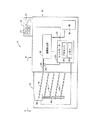
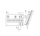
次に図1を参照して、概略側面図が、画像形成部20と、画像形成部20に取り付けた画像形成後仕上げ装置40とを有する、画像形成装置10の精選された構成要素を示す。画像形成部20は、画像形成媒体(紙30等)を第1の紙経路21に沿って画像形成部22まで動かすことによって、その画像形成媒体上に画像を形成するよう構成されている。画像形成部22において、画像形成媒体上に画像を生成することができる。画像形成部22は、たとえば、レーザー画像形成部やインクジェット画像形成部であってもよい。いったん画像形成が行われると、画像形成媒体のシートは、第2の紙経路23に沿って仕上げ装置40まで動く。画像形成部20はさらに、コントローラ部25を含んでもよい。コントローラ部25は、図示のように、プロセッサ26とコンピュータ可読メモリデバイス28(RAMおよび/またはROMのメモリ構成要素等)とを含む。コントローラ25を用いて、画像形成部22による画像生成やユーザインターフェース11を介してのユーザとの通信(情報のやりとり、communication)等、画像形成部20の動作機能を制御することができる。ユーザインターフェース11は、ユーザ入力ポイント(user-input points)(ボタンまたはスイッチ13等)、およびユーザディスプレイ12を含んでもよい。ユーザディスプレイ12によって、コントローラはユーザにメッセージを表示することができる。図示の例において、画像形成部20はまた、シートカウントセンサ24も含む。シートカウントセンサ24は、コントローラ25と信号をやり取りし、シートカウントセンサ24を用いて、仕上げ装置40に転送されている、画像形成した媒体のシートの数をカウントすることができる。
Referring now to FIG. 1, a schematic side view illustrates selected components of an
図1に示すように、仕上げ装置40は複数のシートスタックトレイ42を含む。シートスタックトレイ42の上に、画像形成部20からの画像形成した媒体のシートを置くことができる。仕上げ装置はさらに、仕上げユニット44を含む。仕上げユニット44は、たとえば、ホチキス留めユニット、端部を綴るユニット、糸綴じユニット、または穴あけユニットであってもよい。図示の例において、仕上げユニット44は、ガイド46に沿って上下に動き、単一の仕上げユニットを用いてすべてのトレイ42の要求に応えるようになってもよい。仕上げ装置40にはさらに、シートスタック押さえ装置が設けられている。シートスタック押さえ装置は、図1には示していないが図2以下の図に示し、次に説明する。
As shown in FIG. 1, the finishing
図1の画像形成装置10は、内蔵式装置であってもよく、二部式の(ツーパートの)装置であってもよいことが理解されよう。二部式の装置の場合には、仕上げ装置40は画像形成部20から分離可能であってもよい。
It will be understood that the
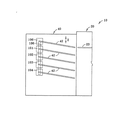
次に図2を参照して、部分平面図により、図1の画像形成装置10および画像形成後仕上げ装置40を示す。図2において、画像形成部20から仕上げ装置40までの画像形成した媒体のシートを供給する紙経路23を見ることができる。画像形成媒体(紙「P」)が、出力紙経路23からトレイ42上へと向き「X」に動く。画像形成媒体「P」のシートは、トレイ42上に積もってシートスタックを形成することができる。それぞれの新しいシート「P」がシートスタック上に置かれると、シートスタックを合わせて保持するようにシートスタック押さえ装置100が設けられている。シートスタック押さえ装置100の動作については、以下でより十分に説明する。上述のように、仕上げユニット44は、シートスタックに画像形成後仕上げを適用することができる。仕上げユニット44と押さえ装置100を両方とも、コントローラ25によって制御することができる。
Next, referring to FIG. 2, the
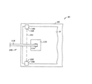
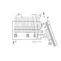
次に図3を参照して、図2に示す画像形成装置10および画像形成後仕上げ装置40の部分側断面図を示す。図3は、仕上げ装置40に単一のシートスタック押さえ装置100を設ける方法を示す。シートスタック押さえ装置100は、ガイドレール106に沿って向き「Z」に動くことができ、それによって、単一の押さえ装置がすべてのシートスタックトレイ42の要求に応えることができるようにする。または、それぞれのトレイ42に、押さえ装置ユニット100、101、102、103、104で示す、専用のシートスタック押さえ装置を設けてもよい。
Next, referring to FIG. 3, a partial side sectional view of the
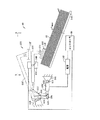
図4は、図2および図3に示す画像形成後仕上げ装置40の詳細、特にシートスタック押さえ装置100の詳細を示す側面図である。複数の画像形成媒体「P」のシートからなるシートスタック「SS」を、シートスタックトレイ42上に支持して示す。図示の例において、シートスタック押さえ装置100は、シートスタック「SS」を押し付けるよう構成されたパッド112を含む。パッド112は、アーム116の第1の端部において、パッド支持部110を介してアーム116によって支持されている。回転可能なパッドコネクタ114によって、パッド112がアーム116に関して回転することができ、パッドがシートスタック「SS」との全面的な接触を維持することができるようになっている。パッド112を平らな部材として示すが、パッドは、シートスタック「SS」の一番上のシートに接触してシートスタックをトレイ42に押し付けるいかなる構成であってもよいことが理解されよう。たとえば、「パッド」112は、棒であっても、1つまたはそれよりも多いフィンガーであっても、1つまたはそれよりも多いローラであってもよい。本例においてはL字形のアーム116が、アーム枢軸接続部(ピボット)118において、フレーム部材140によって枢動可能に支持されている。アーム116の第2の端部125は、アクチュエータコネクタ部材124および枢軸接続ピン126を介して、アクチュエータ120に接続されている。アクチュエータ120は、電源142によって作動することができ、電源142は、コントローラ25によって制御することができる。フレーム部材140と、アーム116上のピン138との間には、戻りばね136が配置されている。戻りばね136は、アーム116を、したがってパッド112を、図4の実線で示す位置へと付勢する。
FIG. 4 is a side view showing details of the post-image forming finishing
動作において、シートスタック押さえ装置100は、第1の位置(二点鎖線のアーム116’およびパッド112’で示す)から可変の第2の位置(実線のアーム116およびパッド112で示す)まで、動作可能である。第1の位置において、シートスタック押さえ装置100のパッド112’は、シートスタック「SS」から離れた状態で後退しており、第2の位置において、パッド112はシートスタック「SS」をシートスタックトレイ42に押し付けている。シートスタック押さえ装置100は、コントローラ25およびアクチュエータ120によって、第1の位置と第2の位置との間を選択的に周期的に移動することができる。アクチュエータ120は、アクチュエータ枢軸接続部122によってフレーム部材141に枢動可能に支持されてシートスタック押さえ装置100にコンプライアンス(変位)を導入することができ、アーム116’が第1の位置にあるときには、アクチュエータ120が二点鎖線の120’で示す位置へと動いて、アーム116およびアクチュエータ120が綴じないようにすることができるようになっている。
In operation, the sheet stack hold down
通常、画像形成媒体の新しいシートがシートスタック「SS」に加わるとき、または、スタックに新しく加えられているシートの前縁部がパッド112に近づくときには、押さえ装置100は第1の(すなわち後退した)位置にある。いったん画像形成媒体のシートがシートスタック「SS」に加わると、押さえ装置100が第2の位置へと周期的移動し、押さえ装置が画像形成媒体のシート(シートスタック「SS」を構成する)をほぼまとまったスタックになるよう保持することができ、したがって、シート間の弾性(loft)を減らし、スタック内でシートが移動するのを防ぐようになっている。仕上げユニット(たとえば、図2の仕上げユニット44)によってシートスタック「SS」に画像形成後仕上げが適用される場合には、押さえ装置100は、シート同士を合わせて第2の位置に保持し続け、仕上げユニットの動作を容易にすることができる。いったん画像形成後仕上げが適用されると、または画像形成ジョブが完了すると(画像形成後仕上げが適用されない場合であっても)、コントローラ25は押さえ装置100を第1の位置(二点鎖線のアーム116’およびパッド112’で示す)に後退させて、シートスタック「SS」をトレイ42から取り除く(図2の矢印「R」で示す)のを容易にすることができる。
Typically, when a new sheet of imaging media joins the sheet stack "SS", or when the leading edge of a sheet newly added to the stack approaches the
シートスタック押さえ装置100の第2の位置(すなわち、パッド112がシートスタック「SS」に接触するとき)は、スタックに新しいシートが加わってシートスタックの厚さ「T」が増大するにつれて、パッド112およびアーム116が、第1の位置(二点鎖線のパッド112’およびアーム116’で示す)の向かって漸進的に動く、という点において、可変である。
The second position of the sheet stack hold down device 100 (i.e., when the
仕上げ装置40はさらに、センサ144を含む。センサ144は、シートスタック押さえ装置100が第2の位置にある場合の、押さえ装置がその時の現在の位置を検出することができる。検出した押さえ装置の位置に基づいて、シートスタック「SS」のおよその厚さ「T」を確定することができる。シートスタック押さえ装置100の位置の検出に応答して、センサ144はシートスタック厚さ信号を生成することができる。このシートスタック厚さ信号を、たとえばコントローラ25が用いて、仕上げユニット44(図2)を制御することができる。図4に示す例において、センサ144は、シートスタック押さえ装置100が所定位置以上になっているかどうかまたは、押さえ装置が所定位置よりも下になっているかどうかを検出する。以下に、センサを用いて第2の位置にある押さえ装置のインクリメントの位置を検出することができる他の実施形態を説明する。
Finishing
次に図5を参照して、図4のシートスタック押さえ装置100およびセンサ144の部分平面図を示す。図示の例において、センサ144は、光源146(フォトアイ(photoeye)等)と光検出器150とを含む。光源146と光検出器150とは、アーム116の両側に間隔を置いて配置されている。アーム116が上向きに(図4の位置116’に向かって)動くと、アームは、光源146が発生する光線151を遮断するすなわち遮ることができ、検出器150が光線151を検出することができないようになっている。アーム116を用いて光源146を遮る代わりに、パッド支持部110(およびパッド112、図4)を用いて光源146を遮ってもよい。
Referring next to FIG. 5, a partial plan view of the sheet
次に図6を参照して、押さえ装置100の他の側面図を示す。図6は、図4と同様であるが、図6においては、押さえ装置100(「可変の第2の位置」にある)を、厚さがTmaxのシートスタック「SS」と係合して示す。(図6におけるシートスタック「SS」の厚さ「Tmax」は、押さえ装置100の動作の説明を容易にする目的で、誇張されている。)見てわかるように、押さえ装置100のアーム116は、センサ144の光源146を遮っており(そしてまた、図5の光検出器150も遮っており)、光線(151、図5)が光検出器で検出できないようになっている。光源146の位置およびアーム116の形状を選択することにより、「Tmax」の所定の値に応じて光源146(および光検出器150、図5)がアーム116で遮られるようにすることができる。いったんアーム116によって光源146(および/または光検出器150)が遮られると、光検出器150(図5)は信号を生成することができる。この信号は、光検出器150が光線151を受け取ったときに生成した先の信号の、中断に対応するものであってもよい。次にこの信号をコントローラ25(図6)が用いて、仕上げユニット(44、図2)を制御してもよい。一例において、「Tmax」は、仕上げユニット(44、図2)をオフにして画像形成後仕上げをシートスタックに適用しないようにするべきシートスタックの厚さとすることができる。たとえば、仕上げユニットがホチキスであり、シートスタックの厚さが「Tmax」以上であるときにはホチキス留め工程をシートスタックに適用するべきではないと判定する場合には、シートスタック「SS」の厚さが「Tmax」に達すると、アーム116が光検出器150(図5)を遮り、したがって、シートスタック厚さ信号を生成する。するとコントローラ25(図4)は、この信号を用いて、ホチキス留めユニットの動作をオフにすることができる。
Next, another side view of the
他の実施形態において、シートスタック厚さ信号を用いて仕上げユニットを選択的にオンにするまたはオフにするのではなく、仕上げユニットは可変に動作可能であってもよい。その場合、シートスタック厚さ信号を用いて、仕上げユニットを可変に動作してもよい。たとえば、仕上げユニットが、さまざまな高さのホチキスの針を生成してさまざまな厚さのシートスタックに対応することができるホチキス留めユニットである場合には、シートスタック厚さ信号を用いて、シートスタックをホチキス留めするのに用いるホチキスの針の高さの選択を容易にすることができる。次に図7を参照して、仕上げ装置(図1の仕上げ装置40等)において用いることができる、他のシートスタック押さえ装置200の側断面図を示す。シートスタック押さえ装置200は、関係するすべての態様において図4のシートスタック押さえ装置100と同様であってもよく、シートスタック押さえ装置200を用いて、シートスタック「SS」を、シートスタックトレイ42に当たった状態で押さえる。図8は、図7とともに考察するべきである。図8は、図7のシートスタック押さえ装置200を示すが、図7と反対の向きから見た側断面図である。シートスタック押さえ装置200は、パッド212、パッド支持部210、およびパッド212を支持するアーム216を含む。押さえ装置200は、シートスタック「SS」を押さえる第2の位置において示す。図4の押さえ装置100と同様に、図7および図8の押さえ装置200は、可変の第2の位置を有することができ、シートスタック「SS」の厚さ「Tx」が増大するにつれて、パッド212、パッド支持部210、およびアーム216が上向きの「U」の向きに漸進的に動くようになっている。
In other embodiments, rather than using the sheet stack thickness signal to selectively turn on or off the finishing unit, the finishing unit may be variably operable. In that case, the finishing unit may be variably operated using the sheet stack thickness signal. For example, if the finishing unit is a stapling unit that can generate stapling needles of various heights to accommodate sheet stacks of various thicknesses, the sheet stack thickness signal is used to generate the sheet The choice of stapling needle height used to staple the stack can be facilitated. Referring next to FIG. 7, a side cross-sectional view of another sheet stack hold-down
図7および図8に示す例において、図7および図8のシートスタック押さえ装置200は、単一のセンサ(図4および図5のセンサ144等)を有するのではなく、複数のセンサを含むセンサアレイ244を含む。それぞれのセンサは、光源246Aないし246Q(図7)および関連する光検出器250Aないし250Q(図8)を含んでもよい。それぞれの光検出器250A〜Qには、信号線217を設けてもよい。信号線217は、コントローラ25(図1)に接続してもよい。この構成において、光源246Aないし246Q(および/または光検出器250A〜Q)はそれぞれ、シートスタック押さえ装置が可変の第2の位置を通って向き「U」に漸進的に動くにつれて、シートスタック押さえ装置200によって漸進的に遮られてもよい。それぞれの光源246A〜Qおよび/または光検出器250A〜Qが漸進的に遮られるにつれて、関連する光検出器250A〜Qは信号状態を変化させることができ、それぞれの光源/光検出器が遮られるにつれて特有のシートスタック厚さ信号を生成できるようになっている。このようにして、可変のシートスタック厚さ信号を生成することができ、この可変のシートスタック厚さ信号を次にコントローラ(25、図1)が用いて、可変に動作可能な仕上げユニットを可変に制御することができる。一番上の光源246Qおよび/または光検出器250Qが押さえ装置のアーム216によって遮られると、対応するシートスタック厚さ信号を用いて仕上げユニットをオフにすることができる。
In the example shown in FIGS. 7 and 8, the sheet
図4ないし図8に示す例において、センサ144、244を、シートスタック押さえ装置100、200のアーム116、216がセンサの光検出器を遮ることができるように配置して示す。しかし、他の構成を用いてもよい。次に図9を参照して、図9の側面図は、仕上げ装置(たとえば、図1の仕上げ装置40)において用いることができる、他のシートスタック押さえ装置300を示す。シートスタック押さえ装置300は、押さえ装置300を用いて、厚さ「T」のシートスタック「SS」を、シートスタックトレイ42に当たった状態で押さえるという点において、図4の押さえ装置100といくつかの態様において同様である。シートスタック押さえ装置300は、押さえ装置が可変の第2の位置にあるときにシートスタック「SS」の一番上のシートを押し付けるよう構成された、パッド312を含む。さらに、シートスタック押さえ装置300は、第1の位置(図4において116’で示す位置と同様)に後退するよう構成されており、シートスタック「SS」にさらなる画像形成媒体のシートを加えることができるようになっている。パッド312は、パッド支持部310によって支持されており、パッド支持部310は、アーム316の第1の端部においてアーム316によって支持されている。アーム316は、アーム枢軸接続部318によって、フレーム部材340に枢動可能に接続されている。アーム316上のピン338に当たった状態で作用するばね部材336を用いて、アーム316を第2の位置(図示)へと付勢してもよい。アーム316は、アクチュエータ320によって、第1の位置と可変の第2の位置との間を選択的に動いてもよい。1つまたはそれよりも多い結合リンク324を用いて、アーム316の第2の端部322をアクチュエータ320に接続してもよい。
In the examples shown in FIGS. 4 to 8, the
図9に示す構成において、押さえ装置300が第2の位置にあるときに押さえ装置300の位置を検出するのに用いるセンサを、多数のさまざまな場所に配置してもよい。押さえ装置300のそれぞれの構成要素(パッド312、パッド支持部310、アーム316、結合リンク324、およびアクチュエータ320)は、押さえ装置が第2の位置を通って可変に動くときに潜在的に変化する可能性があるので、このような構成要素はそれぞれ、潜在的にセンサとともに用いてシートスタック「SS」の厚さ「T」の見積もりを提供することができる。たとえば、図4のセンサ144と同様に、センサ344Aを用いて、第2の位置にあるアーム316の位置を検出してもよい。さらに、センサ344Bを用いて、パッド312および/またはパッド支持部310の位置を検出してもよく、センサ344Cを用いて結合リンク324の位置を検出してもよく、センサ344Dを用いてアクチュエータ320の位置を検出してもよい。センサ344A、344B、344C、または344Dが光源および光検出器(図5の光源146および光検出器150と同様)を含む場合には、シートスタック押さえ装置が所定の第2の位置にあるときに、それぞれの押さえ構成要素(アーム316、パッド312、パッド支持部310、結合リンク324、またはアクチュエータ320)が光源および/または光検出器を遮ってもよい。したがって、それぞれのセンサ344A〜Dは、シートスタック厚さ信号を生成することができ、このシートスタック厚さ信号をコントローラ(25、図1)が用いて、仕上げユニット(たとえば、図1の仕上げユニット44)の動作を制御することができる。さらに、センサ344A〜Dのそれぞれについてそれぞれの位置において単一のセンサを用いるのではなく、センサアレイ(図7および図8のセンサアレイ244と同様)を用いて、コントローラ(25、図1)が可変に制御可能な仕上げユニットを可変に制御することができるようにしてもよい。
In the configuration shown in FIG. 9, the sensors used to detect the position of the holding
シートスタック押さえ装置の主要な構成要素のうちのひとつ(たとえば、押さえ装置300のアーム316、パッド312、パッド支持部310、結合リンク324、またはアクチュエータ320、図9)に関してセンサを配置することに加えて、押さえ装置の主要な構成要素のうちのひとつに補助的な構成要素を取り付け、この補助的な構成要素をセンサとともに用いてもよい。たとえば、図9に示すように、アーム316に延長部材326を接続してもよい。この場合、センサ344E(光源および光検出器を含んでもよい)を設けて、シートスタック押さえ装置300が所定の第2の位置にあるときに延長部材326が光源および/または光検出器を遮ることができるようになっていてもよい。
In addition to locating the sensors with respect to one of the key components of the sheet stack hold down device (eg, arm 316,
示した図に表すシートスタック押さえ装置100(図4ないし図6)、200(図7および図8)、および300(図9)は単に例示であり、他の構成を用いて、シートスタック押さえ装置およびセンサとともにシートスタックの厚さを示すという同じ機能を果たしてもよい。一般的に、シートスタックの厚さの関数として押さえ位置を通って可変に動くことができ、第1の押さえ位置(第1のシートスタックの厚さに対応する)から第2の押さえ位置(第2のシートスタックの厚さに対応する)へと動いたことを検出され得る1つまたはそれよりも多い構成要素を有する、いかなるシートスタック押さえ装置も、動き(第1の押さえ位置から第2の押さえ位置へ)を検出することができるセンサとともに用いて、本発明の精選された実施形態を実施することができる。 The sheet stack hold down devices 100 (FIGS. 4-6), 200 (FIGS. 7 and 8), and 300 (FIG. 9) shown in the figures shown are merely exemplary, and other configurations may be used to achieve the sheet stack hold down device. And the same function as indicating the thickness of the sheet stack with the sensor. Generally, it is possible to move variably through the hold down position as a function of the thickness of the sheet stack, and to move from the first hold down position (corresponding to the thickness of the first sheet stack) to the second hold down position (second position). Any sheet stack hold-down device having one or more components that can be detected to have moved to the second position (corresponding to the thickness of the two sheet stacks) can be moved (from the first hold down position to the second hold down position). With a sensor capable of detecting (press position), a selected embodiment of the invention can be implemented.
また、図1ないし図9から、本発明の実施形態は、センサ(たとえば、図4のセンサ144、図7のセンサアレイ244、および図9のセンサ344A−E)とともに用いてシートスタックの厚さを見積もることができる、シートスタック押さえ装置(たとえば、図4のシートスタック押さえ装置100、図7の200、および図9の300)を提供する。上述のセンサ(たとえば、センサ144およびセンサアレイ244)は、光源および光検出器を含むものとして説明したが、他のタイプのセンサを用いてもよい。たとえば、センサは、シートスタック押さえ装置が所定の第2の位置に達すると周期的移動する(開くまたは閉じる)ことができるスイッチ(水銀スイッチや近接スイッチ等)であってもよい。一般的に、シートスタック押さえ装置の1つまたはそれよりも多い位置を検出することができるいかなるセンサも用いることができる。さらに、本発明の実施形態はまた、センサとともに用いてシートスタックの厚さを見積もることができるシートスタック押さえ装置を有する仕上げ装置(たとえば、仕上げ装置40)を含む画像形成装置(たとえば、図1の画像形成装置10)も提供する。仕上げ装置は、画像形成装置と一体であってもよく、別個のモジュールであってもよい。
Also, from FIGS. 1-9, embodiments of the present invention may be used with sensors (e.g.,
次に図10を参照して、図10の概略図は、仕上げユニットの動作を制御するのに用いることができる仕上げユニット制御システムの構成要素を示す。仕上げユニット制御システムは、シートスタック押さえ装置(たとえば、上述の実施形態のいずれかによる)とともに用いて、仕上げユニットを制御することができる。本発明の実施形態による画像形成装置(たとえば、図1の画像形成装置10)および/または仕上げ装置(たとえば、図1の仕上げ装置40)は、仕上げユニット制御システムを用いることができる。仕上げユニット制御システムは、図9においてプロセッサ(図1のプロセッサ26等)が可読のコンピュータ可読メモリデバイス28(図1にも示す)を含むものとして示す。コンピュータ可読メモリデバイス28は、たとえば、半導体メモリデバイスの構成要素(リードオンリメモリ(ROM)および/またはランダムアクセスメモリ(RAM))、磁気メモリの構成要素(ハードドライブディスク、ディスケット、または磁気テープ等)、および/または光メモリの構成要素(CDまたはDVD等)であってもよい。メモリデバイス28内には、「画像形成ルーチン」160が記憶されていてもよい。画像形成ルーチン160を用いて、画像形成部(22、図1)の動作を制御してもよい。メモリデバイス28内にはまた、仕上げユニット動作ルーチンが記憶されていてもよい。仕上げユニット動作ルーチンは、プロセッサ(26、図1)が実行してもよい。仕上げユニット動作ルーチンは、シートスタック厚さ信号(図4のセンサ144、図7のセンサアレイ244、および/または図9のセンサ344A−E等の押さえ装置位置センサが生成する)を用いて、プロセッサ(たとえば、図1のプロセッサ26)に仕上げユニット(たとえば、図1の仕上げユニット44)の動作を制御させてもよい。図10に示す例において、仕上げユニット動作ルーチンは「ホチキスの針の選択および/またはホチキス留めをオフにするルーチン」164である。このルーチン164は、次に例示的に説明するように、「ホチキス留めルーチン」162とともに動作してもよい。
Referring now to FIG. 10, the schematic diagram of FIG. 10 illustrates components of a finishing unit control system that can be used to control the operation of the finishing unit. The finishing unit control system can be used with a sheet stack hold-down device (eg, according to any of the embodiments described above) to control the finishing unit. An image forming apparatus (e.g.,
次に図11を参照して、フローチャート400は、仕上げユニット動作ルーチンの制御下でコントローラ(図1のコントローラ25等)が行うことができる例示的な各ステップを示す。図2に示す例において、仕上げユニット動作ルーチンは、図10の「ホチキスの針の選択および/またはホチキス留めをオフにするルーチン」164である。フローチャート400はまた、この工程がコントローラ(図1のコントローラ25等)の制御下で画像形成装置(図1の画像形成装置10等)によって行われていると仮定して、構成されている。さらに、画像形成装置が、図4に示す装置100等の円筒形のシートスタック押さえ装置を設けたシートスタックトレイ上に、画像形成した媒体のシートを配置する、と仮定している。フローチャート400(図11)は、画像形成装置に仕上げユニットを有する仕上げ装置(図1の装置40等)が設けられ、その仕上げユニットは、可変のホチキスの針の長さの選択可能性を有するホチキス留めユニットである、というさらなる仮定に基づいている。
Referring now to FIG. 11, a flowchart 400 illustrates exemplary steps that may be performed by a controller (such as
フローチャート400において、工程はコピージョブが開始するステップ402において始まる。(ステップ402は、いかなるタイプの画像形成ジョブであってもよく、写真複写には限定されない、ということが理解されよう。)ステップ404において、コピーが作成され(図1の画像形成部22によって等)、画像形成を行ったコピーが、1つまたはそれよりも多い排紙トレイ(図1のトレイ42等)内に置かれて1つまたはそれよりも多いシートスタックを形成する。ステップ406において、コントローラは、コピージョブにホチキス留めが選択されたかどうかをチェックする。ホチキス留めは、たとえばユーザが、ユーザ入力ステーション(図1の11等)を介して選択することができ、次にユーザ入力ステーションにより、コントローラに、ホチキス留めルーチン(図10のルーチン162等)を実行可能にさせることができる。ホチキス留めルーチンを用いて、ホチキス留めユニットを制御することができる。ホチキス留めユニットの能力に応じて、ホチキス留めルーチン162(図10)は、シートスタック上の、ホチキスの針を配置する場所(たとえば、端部、特定の角、等)や、用いるホチキスの針の大きさ等のパラメータを、制御することができる。ステップ406において、ホチキス留めが選択されなかった場合には、コントローラはステップ408に進み、押さえ装置を後退させてユーザがコピーを取り除くことができるようにし、その後、ステップ410においてコピージョブが終了する。しかし、ステップ406において、ホチキス留めが選択されたとコントローラが判定する場合には、ステップ412において、コントローラは、指定「フラグ」(そのフラグがセットされるようにする信号を受け取るとプロセッサがメモリ領域(location)にフラグをセットしてもよい)をチェックすることによって、ホチキス留めユニットの処理能力を超えたかどうかをチェックし判定する。フラグをセットする信号を生成するこの方法は、たとえば上述の図4ないし図9に関して本明細書において説明した押さえ装置およびセンサの構成を用いて行ってもよい。つまり、センサからの信号がフラグをセットする信号となり得る。
In flowchart 400, the process begins at
ステップ412において、シートスタックの厚さのためにホチキス留めユニットの処理能力を超えるとコントローラが判定する場合には、ステップ414において、ホチキス留めユニットの処理能力を超えたということを、コントローラが(図1のユーザディスプレイ12等によって)ユーザに通知することができる。すると、ステップ408において、コントローラが押さえ装置を後退させ、ステップ410において、「ホチキスの処理能力を超えた」ことを示すフラグ(ステップ412においてチェックした)がクリアされ、コピージョブが終了する。しかし、ステップ412において、「ホチキスの処理能力を超えた」ことを示すフラグがセットされない(ホチキス留めユニットがシートスタックをホチキス留めすることができる、ということを示す)場合には、ステップ416において、コントローラが、セットされている現在のスタック厚さのフラグに基づいて、(シートスタックの厚さに対応する)適切なホチキスの針の大きさを選択する。さまざまな「シート厚さ」のフラグをセットする方法は、図7および図8に関して上述した。(シート厚さに対応して数個のフラグが準備され、センサの信号に基づいてフラグがセットされる。)いったん適切なホチキスの針の大きさが選択されると、ステップ418において、コントローラはホチキス留めユニットに、シートスタックをホチキス留めさせてもよい。ホチキス留め工程に続いて、ステップ408において押さえ装置が後退し、ステップ410においてスタック厚さのフラグがクリアされ、コピージョブが終了する。
If, at
図11のフローチャート400に示す各ステップは単に例示であり、さらなる、これよりも少ない、または他のステップを用いて本発明の方法の精選された実施形態に含まれる行為を行ってもよいことが理解されよう。たとえば、フローチャート400に関して説明したホチキス留めユニットが、ホチキスの針の大きさを可変にする能力を有していない場合には、ステップ416を削除してもよい。さらに、たとえば、押さえ装置がシートスタックに、トレイからシートスタックを取り除くのを妨げたり押さえ装置を損傷したりする力を及ぼさない場合等には、ステップ408(コントローラが押さえ装置を後退させる)を省いてもよい。
The steps shown in flowchart 400 of FIG. 11 are merely exemplary, and additional, fewer, or other steps may be used to perform the actions involved in selected embodiments of the method of the present invention. Will be understood. For example, if the stapling unit described with respect to flowchart 400 does not have the ability to vary the stapler size,
本発明のさらなる実施形態は、仕上げユニット(図1の仕上げユニット40等)の動作の制御方法を提供する。方法は、画像形成媒体のシートを有するシートスタックを設けることを含む。シートスタックは、たとえば、図1の画像形成部20等、画像形成装置の画像形成部によって供給されてもよい。方法はまた、シートスタックを、シートスタック押さえ装置(押さえ装置100(図4)、200(図8)、または300(図9)等)を用いて、表面(図1のシートスタックトレイ42等)に当たった状態で保持することも含む。次にシートスタック押さえ装置の位置が検出される(たとえば、図4のセンサ144、図8のセンサアレイ244、または図9のセンサ344A−Eのうちのいずれかを用いて)。次にシートスタック押さえ装置の検出した位置を用いて、仕上げユニットの動作を制御する。一例において、仕上げユニットを制御することは、図11のフローチャート400のステップ412、414に関して例示的に上述したように、仕上げユニットの動作を選択的にオンにするまたはオフにすることを含む。
A further embodiment of the present invention provides a method of controlling the operation of a finishing unit (such as finishing
本発明の他の実施形態は、シートスタックに接触するよう構成されたシートスタック押さえ装置(それぞれ図4、図8、および図9の押さえ装置100、200、または300等)とともに用いる、仕上げユニット(図1の仕上げユニット40等)を制御する、仕上げユニット制御システムを提供する。仕上げユニット制御システムは、センサを含む。センサは、シートスタック押さえ装置がシートスタックに接触するときにシートスタック押さえ装置の位置を検出することができ、シートスタック押さえ装置の検出した位置に応答して信号を生成することができる。用いてもよい例示的センサには、図4のセンサ144、図8のセンサアレイ244、または図9のセンサ344A〜Eのうちのいずれか、が含まれる。制御ユニットはさらに、センサから信号を受け取りそれに応答して仕上げユニットを制御するよう構成されたプロセッサ(たとえば、図1のプロセッサ26)を含む。一例において、センサは、シートスタック押さえ装置が所定位置以上であるであるときのみに、シートスタック押さえ装置の位置を検出するよう配置される。この例を、図4および図6に示す。図4において、センサ144からの光源146は、押さえユニット100のアーム116によって遮られていないが、図6においては、シートスタックの厚さが「Tmax」であるときには、アーム116(現在「所定位置」にある)が光源146を遮り、したがって、センサ144は押さえ装置を検出することができる。制御ユニットはまた、プロセッサ(たとえば、図1のプロセッサ26)が可読のコンピュータ可読メモリデバイス(たとえば、図1および図10のメモリデバイス28)も含んでもよい。仕上げユニット制御ルーチンは、メモリデバイスに記憶しプロセッサが実行可能であってもよい。仕上げユニット制御ルーチンの非限定的な例の一つは、上述の、図10の「ホチキスの針の選択および/またはホチキス留めをオフにするルーチン」164である。仕上げユニット制御ルーチンは、センサによって生成された信号を用いて、プロセッサに仕上げユニットの動作を制御させてもよい。この信号を用いてプロセッサに仕上げユニットを制御させる仕上げユニット制御ルーチンの非限定的な例の一つは、図11のフローチャート400に示した。
Another embodiment of the present invention is a finishing unit (such as a holding
仕上げユニット制御システムはさらに、シートスタック押さえ装置がシートスタックに接触するときにシートスタック押さえ装置の位置を選択的に検出することができる、複数のセンサを含むことができる。この構成の一例を、図7および図8に示す。図7および図8において、アーム216によって、センサアレイ244の光検出器150A〜Qをそれぞれの光源246A〜Qから漸進的に遮ることができる。アーム216によって遮られた光検出器250A〜Qに基づいて、センサアレイ244は特有の信号を生成することができ、したがって、プロセッサ(26、図1)がアームの位置を選択的に検出することができるようにする。この例において、図11のフローチャート400のステップ416に関して例示的に説明したように、プロセッサ(26、図1)がこの特有の信号を用いて仕上げ装置を選択的に制御することができる。
The finishing unit control system can further include a plurality of sensors that can selectively detect the position of the sheet stack hold down device when the sheet stack hold down contacts the sheet stack. An example of this configuration is shown in FIGS. 7 and 8,
本発明は、コピー機写真、複写機、ファクシミリ機等の画像形成装置に適用することができる。 INDUSTRIAL APPLICABILITY The present invention can be applied to an image forming apparatus such as a photocopier, a copier, and a facsimile machine.
22 画像形成部
25 コントローラ
26 プロセッサ
28 メモリ
30 紙
142 電源
160 画像形成ルーチン
162 ホチキス留めルーチン
164 ホチキスの針の選択および/またはホチキス留めをオフにするルーチン
22
Claims (10)
前記シートスタックを支持するよう構成されたシートスタックトレイと、
第1の位置から可変の第2の位置まで動作可能であり、該第2の位置にあるときに、前記シートスタックを前記シートスタックトレイに押し付ける、シートスタック押さえ装置と、
該シートスタック押さえ装置が前記第2の位置にあるときに該シートスタック押さえ装置の位置を検出し、それによって、該シートスタック押さえ装置の前記第2の位置に基づいて前記シートスタックのおよその厚さを確定することができる、センサと
を備えることを特徴とする仕上げ装置。 A finishing device configured to receive a sheet of an image forming medium forming a sheet stack from the image forming device,
A sheet stack tray configured to support the sheet stack;
A sheet stack holding device operable from a first position to a variable second position, and pressing the sheet stack against the sheet stack tray when in the second position;
Detecting the position of the sheet stack hold-down device when the sheet stack hold-down device is at the second position, thereby detecting the approximate thickness of the sheet stack based on the second position of the sheet stack hold-down device; And a sensor capable of determining the finish.
前記シートスタックに画像形成後仕上げ工程を適用するよう構成された仕上げユニットをさらに含み、
前記シートスタック押さえ装置が前記第2の位置にあるときに前記シートスタック押さえ装置の位置を検出することに応答して、前記センサが、前記仕上げユニットを制御するのに用いることができるシートスタック厚さ信号を生成することを特徴とする請求項1に記載の仕上げ装置。 A finishing device,
Further comprising a finishing unit configured to apply a post-imaging finishing step to the sheet stack,
In response to detecting the position of the sheet stack hold down device when the sheet stack hold down device is in the second position, the sensor may be used to control the finishing unit in a sheet stack thickness. The finishing device according to claim 1, wherein the finishing device generates a signal.
前記センサは、光源と光検出器とを備え、
該光検出器は、前記シートスタック押さえ装置が前記可変の第2の位置の所定位置にあるときに、前記シートスタック押さえ装置によって遮ることができることを特徴とする請求項1に記載の仕上げ装置。 A finishing device,
The sensor includes a light source and a light detector,
The finishing device according to claim 1, wherein the photodetector can be blocked by the sheet stack holding device when the sheet stack holding device is at a predetermined position of the variable second position.
前記シートスタック押さえ装置は、前記シートスタックを押し付けるよう構成されたパッドと、該パッドを支持するアームとを備え、
前記シートスタック押さえ装置が前記所定位置にあるときに、前記パッドまたは前記アームのひとつが前記光検出器を遮ることができることを特徴とする請求項3に記載の仕上げ装置。 A finishing device,
The sheet stack holding device includes a pad configured to press the sheet stack, and an arm supporting the pad.
4. The finishing apparatus according to claim 3, wherein the pad or one of the arms can block the photodetector when the sheet stack holding device is at the predetermined position.
前記シートスタック押さえ装置は、前記シートスタックを押し付けるよう構成されたパッドと、該パッドを支持するアームと、前記シートスタック押さえ装置を前記第1の位置と前記第2の位置との間で選択的に動かすよう構成されたアクチュエータと、該アクチュエータを前記アームに接続する少なくとも1つの結合リンクとを備え、
前記シートスタック押さえ装置が前記所定位置にあるときに、前記パッド、前記アーム、前記アクチュエータ、または前記結合リンクのひとつが前記光検出器を遮ることができることを特徴とする請求項3に記載の仕上げ装置。 A finishing device,
The sheet stack holding device includes a pad configured to press the sheet stack, an arm supporting the pad, and a sheet stack holding device selectively between the first position and the second position. And an at least one coupling link connecting the actuator to the arm;
The finishing device according to claim 3, wherein one of the pad, the arm, the actuator, or the coupling link can block the photodetector when the sheet stack holding device is at the predetermined position. apparatus.
前記シートスタック押さえ装置は、前記シートスタックを押し付けるよう構成されたパッドと、該パッドを支持するアームと、該アームに接続された延長部材とを備え、
該延長部材は、前記シートスタック押さえ装置が前記所定位置にあるときに前記光検出器を遮ることができることを特徴とする請求項3に記載の仕上げ装置。 A finishing device,
The sheet stack holding device includes a pad configured to press the sheet stack, an arm supporting the pad, and an extension member connected to the arm.
The finishing device according to claim 3, wherein the extension member can block the light detector when the sheet stack holding device is at the predetermined position.
前記媒体のシートをシートスタックにして受け取るよう構成された、シートスタックトレイと、
第1の位置から可変の第2の位置まで動作可能であり、該第2の位置にあるときに、前記シートスタックを前記シートスタックトレイに押し付ける、シートスタック押さえ装置と、
該シートスタック押さえ装置が前記第2の位置にあるときに該シートスタック押さえ装置の位置を検出し、それによって、前記シートスタックのおよその厚さを確定しそれに応答してスタック厚さ信号を生成することができる、センサと、
前記スタック厚さ信号によって制御することができる、仕上げユニットと
を備えることを特徴とする画像形成装置。 An image forming apparatus configured to generate an image on a sheet of an image forming medium,
A sheet stack tray configured to receive the sheets of the medium in a sheet stack;
A sheet stack holding device operable from a first position to a variable second position, and pressing the sheet stack against the sheet stack tray when in the second position;
Detecting the position of the sheet stack retainer when the sheet stack retainer is in the second position, thereby determining an approximate thickness of the sheet stack and generating a stack thickness signal in response thereto A sensor that can
An image forming apparatus, comprising: a finishing unit that can be controlled by the stack thickness signal.
該プロセッサにより可読のコンピュータ可読メモリデバイスと、
該メモリデバイスに記憶され前記プロセッサによって実行可能であり、前記スタック厚さ信号を用いて前記プロセッサに前記仕上げユニットの動作を制御させる、仕上げユニット動作ルーチンと、
をさらに含むことを特徴とする請求項7に記載の画像形成装置。 An image forming apparatus, wherein the processor is configured to control operation of the finishing unit using the sheet stack thickness signal; and
A computer readable memory device readable by the processor;
A finishing unit operating routine stored in the memory device, executable by the processor, and using the stack thickness signal to cause the processor to control the operation of the finishing unit;
The image forming apparatus according to claim 7, further comprising:
前記プロセッサはさらに、前記ユーザディスプレイにメッセージを送るよう構成され、
前記シートスタック厚さ信号を用いて前記仕上げユニットをオフにすることができ、
前記シートスタック厚さ信号を用いて前記仕上げユニットをオフにするときには、前記プロセッサが前記ユーザディスプレイにメッセージを送ることを特徴とする請求項9に記載の画像形成装置。 An image forming apparatus, further comprising a user display,
The processor is further configured to send a message to the user display;
The finishing unit can be turned off using the sheet stack thickness signal;
The image forming apparatus of claim 9, wherein the processor sends a message to the user display when the finishing unit is turned off using the sheet stack thickness signal.
Applications Claiming Priority (1)
| Application Number | Priority Date | Filing Date | Title |
|---|---|---|---|
| US10/313,481 US6773004B2 (en) | 2002-12-06 | 2002-12-06 | Methods and apparatus to estimate the thickness of a sheet stack |
Publications (2)
| Publication Number | Publication Date |
|---|---|
| JP2004189489A true JP2004189489A (en) | 2004-07-08 |
| JP2004189489A5 JP2004189489A5 (en) | 2006-11-30 |
Family
ID=32468262
Family Applications (1)
| Application Number | Title | Priority Date | Filing Date |
|---|---|---|---|
| JP2003406158A Withdrawn JP2004189489A (en) | 2002-12-06 | 2003-12-04 | Method and device for estimating thickness of sheet stack |
Country Status (2)
| Country | Link |
|---|---|
| US (1) | US6773004B2 (en) |
| JP (1) | JP2004189489A (en) |
Cited By (1)
| Publication number | Priority date | Publication date | Assignee | Title |
|---|---|---|---|---|
| JP2016064922A (en) * | 2014-09-26 | 2016-04-28 | 日本電気株式会社 | Device and method for superposing sheets |
Families Citing this family (19)
| Publication number | Priority date | Publication date | Assignee | Title |
|---|---|---|---|---|
| US7048273B2 (en) * | 2002-02-28 | 2006-05-23 | Bowe Bell + Howell Company | System and method for monitoring grouped resources |
| US7159746B2 (en) * | 2003-09-26 | 2007-01-09 | Duff William G | Staple-forming apparatus |
| JP2007062918A (en) * | 2005-08-31 | 2007-03-15 | Hitachi Omron Terminal Solutions Corp | Paper sheet piling device |
| US7537206B2 (en) * | 2005-09-15 | 2009-05-26 | Kabushiki Kaisha Toshiba | Sheet alignment apparatus and sheet post-processing apparatus |
| JP4706486B2 (en) * | 2006-01-18 | 2011-06-22 | コニカミノルタビジネステクノロジーズ株式会社 | Bookbinding apparatus and image forming system |
| US20080023909A1 (en) * | 2006-07-28 | 2008-01-31 | Hewlett-Packard Company | Media tray |
| US20100250186A1 (en) * | 2009-03-31 | 2010-09-30 | Pitney Bowes Inc. | System for measuring thickness of mailpieces |
| US8585046B2 (en) * | 2010-04-23 | 2013-11-19 | Xerox Corporation | Horizontal sensor and variable pattern for detecting vertical stacker position |
| TWI409209B (en) * | 2011-03-04 | 2013-09-21 | Primax Electronics Ltd | Sheet stack thickness estimating device |
| CN102679841B (en) * | 2011-03-16 | 2014-10-29 | 致伸科技股份有限公司 | Paper thickness detection device |
| TW201238770A (en) * | 2011-03-23 | 2012-10-01 | Hon Hai Prec Ind Co Ltd | Electronic device |
| TWI432374B (en) * | 2012-04-20 | 2014-04-01 | Primax Electronics Ltd | Sheet thickness estimating device |
| SE537530C2 (en) * | 2013-04-26 | 2015-06-02 | Plockmatic Int Ab | Booklet making machine with thickness sensor |
| US9069315B2 (en) * | 2013-10-16 | 2015-06-30 | Lexmark International, Inc. | Method for measuring media stack height using a translatable height sensor |
| US9216872B2 (en) | 2013-10-16 | 2015-12-22 | Lexmark International, Inc. | Reduced component translatable media stack height sensor assembly |
| US9400173B2 (en) * | 2013-10-16 | 2016-07-26 | Lexmark International, Inc. | Translatable media stack height sensor assembly |
| JP6582541B2 (en) | 2014-06-16 | 2019-10-02 | 株式会社リコー | Sheet processing apparatus and image forming system |
| JP6521577B2 (en) * | 2014-06-16 | 2019-05-29 | キヤノン株式会社 | Image forming apparatus and control method thereof |
| JP6829813B2 (en) * | 2017-03-08 | 2021-02-17 | 株式会社リコー | Binding device and image forming device |
Family Cites Families (27)
| Publication number | Priority date | Publication date | Assignee | Title |
|---|---|---|---|---|
| US4318555A (en) * | 1980-01-15 | 1982-03-09 | Eastman Kodak Company | Stapler |
| US4852867A (en) * | 1986-10-09 | 1989-08-01 | Minolta Camera Kabushiki Kaisha | Copying apparatus having an automatic document feeder with document circulating function and a paper container with paper binding function |
| JPS63235259A (en) * | 1987-03-20 | 1988-09-30 | Canon Inc | Post treatment device for sheet |
| US4878656A (en) * | 1987-03-20 | 1989-11-07 | Canon Kabushiki Kaisha | Sheet finisher |
| JP2589341B2 (en) * | 1988-03-14 | 1997-03-12 | キヤノン株式会社 | Sheet binding apparatus and sheet post-processing apparatus including the same |
| JPH0289771A (en) * | 1988-09-26 | 1990-03-29 | Ricoh Co Ltd | Image forming device |
| JPH02233296A (en) * | 1989-03-07 | 1990-09-14 | Ricoh Co Ltd | Image forming apparatus |
| US5056774A (en) * | 1989-04-18 | 1991-10-15 | Ricoh Company, Ltd. | Finisher for an image forming apparatus |
| JPH0435994A (en) * | 1990-05-31 | 1992-02-06 | Toshiba Corp | Paper sheet binding apparatus and image forming apparatus having the same apparatus |
| US5110102A (en) | 1990-07-10 | 1992-05-05 | Ikegami Tsushinki Co., Ltd. | Article pressing device and sorter with the same |
| JPH0489294A (en) * | 1990-07-31 | 1992-03-23 | Toshiba Corp | Image formation device |
| JP2916033B2 (en) * | 1991-08-27 | 1999-07-05 | キヤノン株式会社 | Image forming device |
| JP3088563B2 (en) * | 1992-07-13 | 2000-09-18 | 池上通信機株式会社 | Sheet alignment device and sorter |
| US5476233A (en) * | 1992-12-14 | 1995-12-19 | Tohoku Ricoh Co., Ltd. | Stacker |
| NL9301345A (en) | 1993-08-02 | 1995-03-01 | Oce Nederland Bv | Method and apparatus for handling copy sets corresponding to an original set. |
| JP2868691B2 (en) * | 1993-08-25 | 1999-03-10 | シャープ株式会社 | Sheet post-processing equipment |
| US5462265A (en) | 1994-11-07 | 1995-10-31 | Xerox Corporation | Variable force sheets or set ejector |
| DE4444488A1 (en) | 1994-12-14 | 1996-06-20 | Kodak Ag | Device for guiding and holding down of sheets in stack in container |
| DE19532108C2 (en) * | 1995-08-31 | 1998-09-03 | Kodak Ag | Storage unit of a copying device |
| US5599009A (en) | 1995-10-05 | 1997-02-04 | Xerox Corporation | Stacking height estimation correction system |
| US5961115A (en) * | 1997-05-09 | 1999-10-05 | Lexmark International Inc. | Method and system of sensing an output level of an output stack of print media in an image forming apparatus |
| JP3667999B2 (en) | 1997-07-22 | 2005-07-06 | 株式会社リコー | Paper processing device |
| DE19813662A1 (en) | 1998-03-27 | 1999-09-30 | Eastman Kodak Co | Device for feeding, depositing and aligning sheets in a stacking container |
| JPH11301919A (en) * | 1998-04-17 | 1999-11-02 | Ricoh Co Ltd | Paper sheet post-processing device |
| JP2000219409A (en) * | 1999-01-29 | 2000-08-08 | Canon Inc | Sheet processing device and image forming device provided therewith |
| US6279899B1 (en) * | 1999-09-03 | 2001-08-28 | Lexmark International, Inc. | Substrate sensing mechanism for use in a printer output bin |
| US6367793B1 (en) | 1999-12-28 | 2002-04-09 | Pitney Bowes Inc. | System and method for document input control |
-
2002
- 2002-12-06 US US10/313,481 patent/US6773004B2/en not_active Expired - Lifetime
-
2003
- 2003-12-04 JP JP2003406158A patent/JP2004189489A/en not_active Withdrawn
Cited By (1)
| Publication number | Priority date | Publication date | Assignee | Title |
|---|---|---|---|---|
| JP2016064922A (en) * | 2014-09-26 | 2016-04-28 | 日本電気株式会社 | Device and method for superposing sheets |
Also Published As
| Publication number | Publication date |
|---|---|
| US20040108644A1 (en) | 2004-06-10 |
| US6773004B2 (en) | 2004-08-10 |
Similar Documents
| Publication | Publication Date | Title |
|---|---|---|
| JP2004189489A (en) | Method and device for estimating thickness of sheet stack | |
| US9902183B2 (en) | Sheet processing apparatus and image forming apparatus | |
| JP3740400B2 (en) | Sheet material processing apparatus and image forming apparatus | |
| US8276900B2 (en) | Sheet processing apparatus and image forming apparatus equipped with the same | |
| EP2026138B1 (en) | Image forming system and image forming apparatus | |
| JP5988792B2 (en) | Sheet processing apparatus and image forming apparatus | |
| US8406681B2 (en) | Sheet processing apparatus capable of performing a punch process and image forming system having same | |
| JP2008238694A (en) | Bookbinding system and bookbinding apparatus | |
| JP5421178B2 (en) | Sheet cutting apparatus, sheet post-processing apparatus including the sheet cutting apparatus, and image forming system | |
| JP4434800B2 (en) | Sheet processing device | |
| JP2006076779A (en) | Sheet handling device and image forming device using it | |
| JP4208321B2 (en) | Sheet stacking device | |
| JP2016135704A (en) | Sheet processing device and image formation device equipped with the same | |
| JPH1159975A (en) | Paper feeding device | |
| JP3907335B2 (en) | Sheet stacking device | |
| JP2019182600A (en) | Sheet discharge device and image formation device | |
| JP2005075573A (en) | Sheet handling device and image forming device having the device | |
| JP2005145625A (en) | Sheet processor and image forming device with the same | |
| JP2012096917A (en) | Sheet post-processing device | |
| JP4310305B2 (en) | Sheet stacking device | |
| JP2010240799A (en) | Sheet cutting device, sheet postprocessing device equipped therewith, and image forming system | |
| JP4089388B2 (en) | Post-processing equipment | |
| JP2638960B2 (en) | Image forming device | |
| JP3860918B2 (en) | Image forming apparatus | |
| JP3907336B2 (en) | Image forming apparatus |
Legal Events
| Date | Code | Title | Description |
|---|---|---|---|
| A521 | Request for written amendment filed |
Free format text: JAPANESE INTERMEDIATE CODE: A523 Effective date: 20061012 |
|
| A621 | Written request for application examination |
Free format text: JAPANESE INTERMEDIATE CODE: A621 Effective date: 20061012 |
|
| A761 | Written withdrawal of application |
Free format text: JAPANESE INTERMEDIATE CODE: A761 Effective date: 20080508 |