JP2004188974A - Rubber blanket cylinder for offset press - Google Patents
Rubber blanket cylinder for offset press Download PDFInfo
- Publication number
- JP2004188974A JP2004188974A JP2003396258A JP2003396258A JP2004188974A JP 2004188974 A JP2004188974 A JP 2004188974A JP 2003396258 A JP2003396258 A JP 2003396258A JP 2003396258 A JP2003396258 A JP 2003396258A JP 2004188974 A JP2004188974 A JP 2004188974A
- Authority
- JP
- Japan
- Prior art keywords
- rubber blanket
- blanket cylinder
- foil
- cylinder
- surface area
- Prior art date
- Legal status (The legal status is an assumption and is not a legal conclusion. Google has not performed a legal analysis and makes no representation as to the accuracy of the status listed.)
- Withdrawn
Links
Images


Classifications
-
- B—PERFORMING OPERATIONS; TRANSPORTING
- B41—PRINTING; LINING MACHINES; TYPEWRITERS; STAMPS
- B41F—PRINTING MACHINES OR PRESSES
- B41F13/00—Common details of rotary presses or machines
- B41F13/08—Cylinders
- B41F13/193—Transfer cylinders; Offset cylinders
Landscapes
- Engineering & Computer Science (AREA)
- Mechanical Engineering (AREA)
- Printing Plates And Materials Therefor (AREA)
Abstract
Description
本発明は、請求項1の前提部分おいて書き部に記載のゴムブランケット胴に関する。 The present invention relates to a rubber blanket cylinder according to the preamble of claim 1.
オフセット輪転印刷機において、印刷像は、周知のように、プレート胴もしくは版胴からゴムブランケット胴へ、さらには、このゴムブランケット胴から、印刷胴上を走行する紙の上へと転写される。印刷版からゴムブランケットへのインキの転写だけでなく、同じくゴムブランケットから紙の上への転写もまた、ゴムブランケット胴と、プレート胴もしくは版胴との間、あるいはゴムブランケット胴と対向圧胴との間の線圧と呼ばれる或る決まった最小限の圧力が存在して初めて可能になる。 In an offset rotary printing press, the print image is transferred, as is well known, from a plate cylinder or plate cylinder to a rubber blanket cylinder, and from this rubber blanket cylinder onto the paper running on the print cylinder. Not only the transfer of ink from the printing plate to the rubber blanket, but also the transfer of the rubber blanket onto the paper, between the rubber blanket cylinder and the plate or plate cylinder, or between the rubber blanket cylinder and the counter impression cylinder. This is only possible if there is a certain minimum pressure, called the linear pressure between the two.
ここで、上述したことに関連して、常に拡大しつづける生産性への要求から、あるいは、出来るだけ軽くてコストのかからない印刷版胴を作製する努力を通じて、品質保証に関わる問題が生じてくる。いわゆる溝無し印刷、それも、スリーブ上に溝無しで着設された印刷版、および/または、溝無しで着設されたゴムブランケットに代表されるスリーブ技術の場合にはまさに、胴溝が無いおかげで振動が励起されることが少なくなるので、剛性を低くすることができ、そのため、印刷胴の長さ/厚さ比、もしくは、たわみに関する相対的な自身の剛性は、常に不利になり続けている。この結果、印刷運転中に、不本意にも印刷胴同志の形や姿勢が互いに変化する、すなわち、印刷胴がたわんでしまうことになるのである。 In connection with the above, problems relating to quality assurance arise from the ever-increasing demand for productivity or through efforts to make printing cylinders as light and inexpensive as possible. In the case of the so-called grooveless printing, which is also a sleeve technology typified by a printing plate mounted on the sleeve without grooves and / or a rubber blanket mounted without grooves, there is no barrel groove. The stiffness can be reduced because vibrations are less excited, so that the length / thickness ratio of the printing cylinder, or its own stiffness relative to the deflection, always remains disadvantageous. ing. As a result, during the printing operation, the shapes and postures of the printing cylinders reluctantly change with each other, that is, the printing cylinders bend.
たわみによる位置や姿勢の変化(本明細書中、位置姿勢変化と呼ぶこともある)は、押し当て方、言い換えれば、印刷装置内で協働する印刷胴同志の間の当接圧力を、胴幅に亙って不均一なものに変えてしまう。押し当て方は、通常、いわゆる押し付け跡幅を測定することによって数値的に読み取れる。押し付け跡幅というのは、互いに当接された、つまり押圧状態に持来された胴同志において、胴の接触領域を決めるゾーンの幅のことである。この測定は、オフセット印刷の場合には、とりわけ簡単である。というのも、この場合、胴の対のうち一方の胴が圧縮可能な(柔らかい)表面を有しているからである。 A change in position or orientation due to deflection (also referred to as a position / posture change in this specification) is a method of pressing, in other words, a contact pressure between printing cylinders cooperating in a printing apparatus. It changes to something that is uneven over the width. The pressing method can usually be read numerically by measuring the so-called pressing trace width. The pressing trace width is the width of the zone that determines the contact area of the cylinders when they are brought into contact with each other, that is, brought into a pressed state. This measurement is particularly simple in the case of offset printing. This is because in this case one of the cylinder pairs has a compressible (soft) surface.
こうして残った機械的な調整の欠如により、本明細書において上述した位置姿勢変化のため紙ウェブが幅方向に亙って不均一な速度プロファイルで動くと、周知のように、ゴム胴の印刷間隙において、搬送される紙ウェブに皺が発生する。この場合、紙ウェブの中心は、ウェブの外側よりも早く動き、これが印刷見当合わせ問題を発生させることになる。このような印刷見当合わせ問題に対処するために、今日、様々な方法が用いられている。こうして、ウェブ幅を制御する像調整器(Bildregler)が用いられる。像調整器は、通常、回転するいくつかの小形ホイールであり、これらのホイールが、幅を小さくする轍をウェブ内に押し付ける。この問題を解消するために、特許文献1としての独国特許出願公開第4436973号明細書では、さらに他の方法が開示されている。すなわち、ゴムブランケット(本明細書中ゴムスリーブ)を自身の表面形状に関して凹型もしくは凸型に形成する、つまり胴の軸線方向における外周面が、ゴムブランケット胴上で凸型もしくは凹型の形をなすようにして厚さプロファイルを変化させるというものである。つまり、平らなゴムブランケット/ゴムスリーブと接合された特に凹形に表面加工されたゴムブランケット/ゴムスリーブならびに凹型に切削されて表面加工された胴表面が記載されている。 As is well known, when the paper web moves with a non-uniform velocity profile across the width due to the change in position and orientation described hereinabove due to the lack of mechanical adjustment that remains, as is well known, the printing gap of the blanket cylinder is known. In the above, wrinkles occur on the paper web being conveyed. In this case, the center of the paper web moves faster than the outside of the web, which will cause print registration problems. Various methods are used today to address such print registration problems. Thus, an image conditioner (Bildregler) for controlling the web width is used. The image conditioner is usually a number of small rotating wheels that press a narrowing rut into the web. In order to solve this problem, German Patent Application Publication No. 4436973 as Patent Document 1 discloses another method. That is, the rubber blanket (rubber sleeve in this specification) is formed in a concave or convex shape with respect to its own surface shape, that is, the outer peripheral surface in the axial direction of the cylinder forms a convex or concave shape on the rubber blanket cylinder. To change the thickness profile. That is, a rubber blanket / rubber sleeve, particularly concavely surfaced, joined with a flat rubber blanket / rubber sleeve, and a concavely cut and surfaced torso surface are described.
加えて、ゴムブランケット胴とゴムブランケットとの間に挟み込まれたフォイル形態の下敷きを然るべく配置することで、上述した印刷見当合わせ問題を解消する試みがやはり既になされてきた。かくして、特許文献2としての欧州特許第0704301号明細書は、ゴムブランケットをゴムブランケット胴上で調整してより良好に留めるための貼着性のプラスチックフォイル形態の薄い中間層を開示している。これに対して、ゴムブランケット胴の表面は、薄いフォイルの厚さに対応して、直径が少なくなるようにして形成された凹んだ部分を有している。
従って、本発明の課題は、ゴムブランケットを表面で凹型や凸型に仕上げなくても、あるいはその他の処置をゴムブランケットに講じなくても、さらには、ゴムブランケット胴に施す処置を簡単でコストのかからないものにしながら、ゴムブランケットの搬送特性を制御できるゴムブランケット胴を、輪転印刷における品質保証が可能になるようにして作製することにある。 Therefore, an object of the present invention is to provide a simple and cost-effective treatment for a rubber blanket cylinder without finishing the rubber blanket into a concave or convex shape on the surface or performing other measures on the rubber blanket cylinder. An object of the present invention is to produce a rubber blanket cylinder capable of controlling the transport characteristics of a rubber blanket while ensuring the quality in rotary printing.
この課題は、本発明により、請求項1の特徴部分に記載の構成によって解決される。 This object is achieved according to the invention by a configuration according to the characterizing part of claim 1.
この解決手段は、溝無しのゴムスリーブだけでなく、溝付きのゴムスリーブにも適用できる。 This solution is applicable not only to rubber sleeves without grooves, but also to rubber sleeves with grooves.
以下に本発明を2つの実施形態に基づき説明する。 Hereinafter, the present invention will be described based on two embodiments.
図1は、凹形にカット/表面加工/研磨された胴表面2を有するゴムブランケット胴1を示す。この胴には、前記の如き凹形の表面プロファイルが強制的に押し付けられる平らなゴムブランケットを用いることができる。その結果、ゴムブランケットの表面の側方端部が、ゴムブランケットの中心部に比べて、下方にあるゴムブランケット胴1の回転軸線から半径方向に遠く離れることになる。このようにして得られた表面速度分布(表面速度プロファイル)によって、紙ウェブに係る搬送特性が改善され、皺の形成が解消される。ただ、ゴムブランケット胴における表面加工工程には、それでもやはり手間とコストがかかる。
FIG. 1 shows a rubber blanket cylinder 1 having a
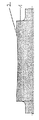
図2は、直径が一様に減らされて回転軸線に平行に延びる凹んだ表面領域4を有する本発明に係るゴムブランケット胴3を示す。この表面領域4には、少なくとも外側が凹形に加工されたフォイル5が挿入され、このフォイルによって、表面領域4が完全に満たされ、ゴムブランケット胴3の外周面には、中心に関して対称に延在する凹形の形状が間接的に与えられている。
FIG. 2 shows a rubber blanket cylinder 3 according to the present invention having a concave surface area 4 which is uniformly reduced in diameter and extends parallel to the axis of rotation. Into this surface region 4 is inserted a
この凹形に加工されたフォイル5は、容易に交換可能な貼着性のプラスチックフォイルにすることができる。このフォイル5は、もちろんそれ自身交換可能なスリーブとして形成されていてもよい。フォイル5は、胴上で(溝付きの、もしくはスリーブとしての)ゴムブランケットを調整するのに役立つ一方、他方では、ローラ中心部分における最適な付着性を与えるのに役立つ。
The
図3は、図2のゴムブランケット胴6を示すが、この胴は、真中に関して対称に凹形にカット/表面加工/研磨された凹んだ表面領域7を有している。この表面領域7内には、平らな、もしくは同じく凹形に加工されたフォイル8をはめ込むことができる。
FIG. 3 shows the rubber blanket cylinder 6 of FIG. 2, which has a concave surface area 7 which is cut / surfaced / polished symmetrically concave with respect to the middle. In this surface region 7, a flat or similarly concavely
3,6・・・ゴムブランケット胴
4,7・・・凹んだ表面領域
5,8・・・フォイル
3,6 ... rubber blanket cylinder 4,7 ...
Claims (2)
印刷幅の中に、ゴムブランケット胴(3,6)の回転軸線に対して略平行に延在する、略一定に直径を低減させた形態の凹んだ表面領域(4,7)が設けられ、該表面領域内に、少なくとも外側が凹形に加工されたフォイル(5,8)が嵌め込まれており、前記フォイルによって前記表面領域(4,7)が満たされていることを特徴とするゴムブランケット胴。 In a rubber blanket cylinder of an offset printing machine for accommodating a flat rubber blanket made of an elastically deformable material,
Within the printing width there is provided a recessed surface area (4, 7) in a substantially reduced diameter form, extending substantially parallel to the axis of rotation of the rubber blanket cylinder (3, 6); A rubber blanket, characterized in that a foil (5, 8) having at least an outer concave shape is fitted into the surface area, and the foil fills the surface area (4, 7). Torso.
前記凹んだ表面領域(7)は、前記ゴムブランケット胴(6)の軸線方向中央に関して対称に、いくらか凹形に表面加工されており、前記表面領域内に、フォイル(8)が嵌め込まれており、前記フォイルによって前記表面領域(7)が満たされていることを特徴とするゴムブランケット胴。
The rubber blanket cylinder according to claim 1,
The recessed surface area (7) is textured somewhat concavely, symmetrically with respect to the axial center of the rubber blanket cylinder (6), in which a foil (8) is fitted. Rubber blanket cylinder, characterized in that said foil is filled in said surface area (7).
Applications Claiming Priority (1)
| Application Number | Priority Date | Filing Date | Title |
|---|---|---|---|
| DE10258048A DE10258048A1 (en) | 2002-12-11 | 2002-12-11 | Blanket cylinders for offset printing machines |
Related Child Applications (1)
| Application Number | Title | Priority Date | Filing Date |
|---|---|---|---|
| JP2007166830A Division JP2007302004A (en) | 2002-12-11 | 2007-06-25 | Rubber blanket cylinder for offset presses |
Publications (1)
| Publication Number | Publication Date |
|---|---|
| JP2004188974A true JP2004188974A (en) | 2004-07-08 |
Family
ID=32319066
Family Applications (2)
| Application Number | Title | Priority Date | Filing Date |
|---|---|---|---|
| JP2003396258A Withdrawn JP2004188974A (en) | 2002-12-11 | 2003-11-26 | Rubber blanket cylinder for offset press |
| JP2007166830A Pending JP2007302004A (en) | 2002-12-11 | 2007-06-25 | Rubber blanket cylinder for offset presses |
Family Applications After (1)
| Application Number | Title | Priority Date | Filing Date |
|---|---|---|---|
| JP2007166830A Pending JP2007302004A (en) | 2002-12-11 | 2007-06-25 | Rubber blanket cylinder for offset presses |
Country Status (4)
| Country | Link |
|---|---|
| US (1) | US6854389B2 (en) |
| EP (1) | EP1428660B1 (en) |
| JP (2) | JP2004188974A (en) |
| DE (2) | DE10258048A1 (en) |
Families Citing this family (2)
| Publication number | Priority date | Publication date | Assignee | Title |
|---|---|---|---|---|
| DE102013103712A1 (en) * | 2013-04-12 | 2014-10-16 | Manroland Web Systems Gmbh | Printing unit and blanket plate for a printing unit |
| EP4000931B1 (en) * | 2019-05-09 | 2023-06-14 | Heidelberger Druckmaschinen AG | Device for measuring elevations of the surface of a rotating body |
Family Cites Families (14)
| Publication number | Priority date | Publication date | Assignee | Title |
|---|---|---|---|---|
| DE1082601B (en) * | 1958-10-31 | 1960-06-02 | Kartonagenmaschinenwerk Kama V | Devices for tensioning the rubber blanket on printing cylinders |
| DE2701670A1 (en) * | 1977-01-17 | 1978-07-20 | Maschf Augsburg Nuernberg Ag | OFFSET ROTARY PRINTING MACHINE |
| DE10257746B3 (en) * | 2002-12-10 | 2004-06-24 | Man Roland Druckmaschinen Ag | Forme cylinder of a rotary printing press, in particular an offset printing press |
| DE3410638A1 (en) * | 1984-03-22 | 1985-10-03 | Albert Handtmann ELTEKA GmbH & Co KG, 7950 Biberach | Cylinder for printing or paper machines |
| US4654571A (en) * | 1985-09-16 | 1987-03-31 | Hinds Walter E | Single plane orthogonally movable drive system |
| JPH06246896A (en) * | 1993-02-26 | 1994-09-06 | Ryobi Ltd | Offset perfecting press |
| DE4436973C2 (en) * | 1993-12-21 | 2003-06-26 | Heidelberger Druckmasch Ag | Blanket with varying profile and process for its manufacture |
| US6105498A (en) * | 1993-12-21 | 2000-08-22 | Heidelberger Druckmaschinen Ag | Varying profile cylinder blanket |
| DE4432816A1 (en) * | 1994-09-15 | 1996-03-21 | Roland Man Druckmasch | Printing roller for channelless printing |
| DE29612105U1 (en) * | 1996-07-11 | 1996-08-22 | Roland Man Druckmasch | Roller in a printing press |
| EP1082601B1 (en) | 1998-05-25 | 2005-08-10 | Jennissen, Herbert P. | Flow-through shear analyzer for biologically active molecules in liquid layers on surfaces, method of analysing a liquid and method of determining the thickness of an ultra thick liquid layer |
| FR2789347B1 (en) * | 1999-02-04 | 2001-04-06 | Rollin Sa | BLANKET WITH VARIABLE SURFACE PROPERTIES FOR PRINTING MACHINE |
| US6513425B1 (en) * | 1999-05-05 | 2003-02-04 | Metso Paper Karlstad Ab | Assembly for positioning a heater in a relation to a roll, and a press device with such an assembly |
| JP3069098B1 (en) * | 1999-09-22 | 2000-07-24 | 株式会社東京機械製作所 | Blanket mounting device and blanket for printing press |
-
2002
- 2002-12-11 DE DE10258048A patent/DE10258048A1/en not_active Withdrawn
-
2003
- 2003-11-26 JP JP2003396258A patent/JP2004188974A/en not_active Withdrawn
- 2003-12-09 DE DE50307316T patent/DE50307316D1/en not_active Expired - Lifetime
- 2003-12-09 EP EP03028072A patent/EP1428660B1/en not_active Expired - Fee Related
- 2003-12-11 US US10/734,796 patent/US6854389B2/en not_active Expired - Fee Related
-
2007
- 2007-06-25 JP JP2007166830A patent/JP2007302004A/en active Pending
Also Published As
| Publication number | Publication date |
|---|---|
| EP1428660A1 (en) | 2004-06-16 |
| DE10258048A1 (en) | 2004-06-24 |
| JP2007302004A (en) | 2007-11-22 |
| US20040123755A1 (en) | 2004-07-01 |
| EP1428660B1 (en) | 2007-05-23 |
| DE50307316D1 (en) | 2007-07-05 |
| US6854389B2 (en) | 2005-02-15 |
Similar Documents
| Publication | Publication Date | Title |
|---|---|---|
| US20120132136A1 (en) | Roller for an Inking System of a Printing Machine | |
| EP0141058B1 (en) | Inker for a printing press | |
| US6860200B2 (en) | Form cylinder of a rotary printing press, in particular of an offset printing press | |
| JP2008087481A (en) | Printer of printing machine | |
| JP2005319784A (en) | Roll crossing method in printing machine | |
| JP2004188974A (en) | Rubber blanket cylinder for offset press | |
| US6810810B2 (en) | Method and device for adjusting a quantity of ink supplied to an impression cylinder of a printing machine | |
| JP2000052625A (en) | Inking roller and method and apparatus for printing | |
| US4681035A (en) | Rotary offset printing machine system | |
| US20070181022A1 (en) | Apparatus and method for controlling the supply of fluid | |
| US5890430A (en) | Impression cylinder having a multiple diameter and a sheet guiding foil | |
| US5809887A (en) | Ink duct of a rotary printing press | |
| JP3342876B2 (en) | Roller with rubber lining and device for mounting rubber lining | |
| US5152221A (en) | Angled doctor blade arrangement for gravure press | |
| JP4044514B2 (en) | Rubber cylinder sleeve for offset printing press | |
| EP2300230B1 (en) | Roller for an inking system of a printing machine | |
| US20040226461A1 (en) | Roll for a printing press and process for manufacturing a roll | |
| US20150309444A1 (en) | Method and System for Adjusting a Gap between Rollers of a Printer in Accordance with a Media or Image Length | |
| JPH0346308B2 (en) | ||
| JP2898597B2 (en) | Dampening device for offset printing press | |
| US5896814A (en) | Ink dosing device for inking units of printing presses | |
| JP2000025201A (en) | Continuous foil transfer machine | |
| JPS61106254A (en) | Keyless inking apparatus | |
| JP5237660B2 (en) | Liquid transfer method and apparatus for sheet-like material | |
| JP2010036518A (en) | Blanket cylinder |
Legal Events
| Date | Code | Title | Description |
|---|---|---|---|
| A977 | Report on retrieval |
Free format text: JAPANESE INTERMEDIATE CODE: A971007 Effective date: 20060406 |
|
| A131 | Notification of reasons for refusal |
Free format text: JAPANESE INTERMEDIATE CODE: A131 Effective date: 20061024 |
|
| A601 | Written request for extension of time |
Free format text: JAPANESE INTERMEDIATE CODE: A601 Effective date: 20070123 |
|
| A602 | Written permission of extension of time |
Free format text: JAPANESE INTERMEDIATE CODE: A602 Effective date: 20070126 |
|
| A521 | Request for written amendment filed |
Free format text: JAPANESE INTERMEDIATE CODE: A523 Effective date: 20070221 |
|
| A02 | Decision of refusal |
Free format text: JAPANESE INTERMEDIATE CODE: A02 Effective date: 20070313 |
|
| A761 | Written withdrawal of application |
Free format text: JAPANESE INTERMEDIATE CODE: A761 Effective date: 20070730 |