JP2004187287A - Image pickup device, control method for the image pickup device, and recording medium stored with computer-readable program executing the control method - Google Patents
Image pickup device, control method for the image pickup device, and recording medium stored with computer-readable program executing the control method Download PDFInfo
- Publication number
- JP2004187287A JP2004187287A JP2003388415A JP2003388415A JP2004187287A JP 2004187287 A JP2004187287 A JP 2004187287A JP 2003388415 A JP2003388415 A JP 2003388415A JP 2003388415 A JP2003388415 A JP 2003388415A JP 2004187287 A JP2004187287 A JP 2004187287A
- Authority
- JP
- Japan
- Prior art keywords
- compensation value
- light
- image sensor
- exposure compensation
- accumulation
- Prior art date
- Legal status (The legal status is an assumption and is not a legal conclusion. Google has not performed a legal analysis and makes no representation as to the accuracy of the status listed.)
- Pending
Links
Images


Classifications
-
- G—PHYSICS
- G03—PHOTOGRAPHY; CINEMATOGRAPHY; ANALOGOUS TECHNIQUES USING WAVES OTHER THAN OPTICAL WAVES; ELECTROGRAPHY; HOLOGRAPHY
- G03B—APPARATUS OR ARRANGEMENTS FOR TAKING PHOTOGRAPHS OR FOR PROJECTING OR VIEWING THEM; APPARATUS OR ARRANGEMENTS EMPLOYING ANALOGOUS TECHNIQUES USING WAVES OTHER THAN OPTICAL WAVES; ACCESSORIES THEREFOR
- G03B7/00—Control of exposure by setting shutters, diaphragms or filters, separately or conjointly
- G03B7/08—Control effected solely on the basis of the response, to the intensity of the light received by the camera, of a built-in light-sensitive device
- G03B7/099—Arrangement of photoelectric elements in or on the camera
Abstract
Description
本発明は、静止画或いは動画が撮影可能なカメラ等の撮像装置における露出量を補償する撮像装置、該撮像装置の制御方法、及び該制御方法を実行するコンピュータにより読み取り可能なプログラムを記憶した記憶媒体に関するものである。 The present invention relates to an imaging apparatus for compensating an exposure amount in an imaging apparatus such as a camera capable of capturing a still image or a moving image, a control method of the imaging apparatus, and a storage storing a computer-readable program for executing the control method. It is about media.
カメラ等の撮像装置に用いる測光装置或いは露出制御装置として、例えば撮影画面内を複数の領域に分割して各領域毎の被写界の複数の輝度情報を得て、所定のアルゴリズムを用いて適正な露出を得ようとする技術が実用化されている(例えば、特許文献1参照)。 As a photometric device or an exposure control device used for an imaging device such as a camera, for example, the inside of a shooting screen is divided into a plurality of regions to obtain a plurality of pieces of luminance information of an object scene for each region, and a predetermined algorithm is used. A technique for obtaining a proper exposure has been put to practical use (for example, see Patent Document 1).
例えば、被写界の輝度情報を得るための測光用センサーの出力に応じて撮像素子の蓄積時間を決定する技術が提案されている(例えば、特許文献2参照)。
一眼レフレックスタイプのカメラにおける測光用センサーは、ペンタプリズムを用いたファインダー光学系の中に組み込まれてピント板と呼ばれる拡散板によって拡散された光線の一部を受光するように構成される場合が多い。この様な構成の場合には、測光用センサーは、ファインダーの接眼レンズに向けられたファインダー光学系の光軸から外れた位置に配置される。この構成では、交換レンズの明るさ(Fナンバー)や、射出瞳の位置、或いは、ピント板の拡散特性に依存して、測光用センサーに入射する光量が様々に変化するため、特に撮影画面内を複数領域に分割して輝度情報を得ようとする場合に、画面の中央付近とその周辺付近の光量バランスが変化してしまう可能性がある。このため、逆光判別などに支障をきたし撮影露出が適正値からはずれてしまうおそれがある。これを極力防止するために、交換レンズからレンズ固有の明るさ(Fナンバー)等の情報をカメラに入力して、測光用センサーの出力信号を補正することも行われているが、全ての交換レンズに対して正確な信号補正を行うのは容易ではない。 A photometric sensor in a single-lens reflex camera may be configured to receive a part of the light beam diffused by a diffusing plate called a focusing plate that is incorporated in a finder optical system using a pentaprism. Many. In such a configuration, the photometric sensor is arranged at a position off the optical axis of the finder optical system directed to the eyepiece of the finder. In this configuration, the amount of light incident on the photometric sensor changes variously depending on the brightness (F number) of the interchangeable lens, the position of the exit pupil, or the diffusion characteristics of the focusing plate. Is divided into a plurality of regions to obtain luminance information, there is a possibility that the light amount balance in the vicinity of the center of the screen and in the vicinity thereof changes. For this reason, it may hinder the backlight determination or the like, and the photographing exposure may deviate from an appropriate value. In order to prevent this as much as possible, information such as brightness (F number) unique to the lens is input to the camera from the interchangeable lens, and the output signal of the photometric sensor is corrected. It is not easy to perform accurate signal correction on a lens.
また、近年普及が加速している撮像素子を用いたデジタルカメラでは、フィルムカメラよりも露出のずれに対するラチチュードが狭いために、僅かな露出のずれがフィルムカメラに比較して、得られる画像に与える影響が大きくなる。 In addition, in digital cameras using an image sensor, which has become increasingly popular in recent years, the latitude for exposure shift is narrower than that of a film camera, so that a slight exposure shift is given to an obtained image as compared with a film camera. The effect is greater.
本発明は上記問題を鑑みてなされたものであり、本発明の目的は、カメラ等の撮像装置に装着されるレンズ装置の個々の特性に起因する誤差、或いは撮像装置本体内の光学部材の個々の特性に起因する誤差の影響をなくし、撮像装置に適正な露出量補償値を設定することができる撮像装置、該撮像装置の制御方法、及び該露出制御方法を実行するコンピュータにより読み込み可能なプログラムを記憶した記憶媒体を提供することにある。 The present invention has been made in view of the above problems, and an object of the present invention is to provide an error caused by individual characteristics of a lens device mounted on an imaging device such as a camera, or an individual optical member in an imaging device body. Imaging apparatus capable of setting an appropriate exposure compensation value in an imaging apparatus by eliminating the influence of an error caused by the characteristic of the imaging apparatus, a control method of the imaging apparatus, and a program readable by a computer that executes the exposure control method The object of the present invention is to provide a storage medium in which is stored.
上記目的を達成するために、請求項1記載の撮像装置は、本体に取り付けられた撮影レンズを通過した光を受けて画像信号を出力する撮像素子と、撮影レンズを通過した光を受けて輝度情報を出力する測光手段と、測光手段の出力に応じて露出量補償値を設定する制御手段とを備えた撮像装置において、制御手段は、測光手段の出力する輝度情報に基づいて第1の露出量補償値を設定し、第1の露出量補償値に基づいて撮像素子に通過した光の第1の蓄積を行わせ、第1の蓄積結果に基づいて第2の露出量補償値を設定し、第2の露出量補償値に基づいて撮像素子に通過した光の第2の蓄積を行わせることを特徴とするものである。 In order to achieve the above object, an image pickup apparatus according to claim 1 includes an image pickup element that outputs an image signal in response to light passing through a photographing lens attached to a main body, and a luminance that receives light passing through the photographing lens. In an imaging apparatus comprising: a photometer for outputting information; and a controller for setting an exposure compensation value in accordance with the output of the photometer, the controller includes a first exposure unit based on luminance information output by the photometer. An amount compensation value is set, a first accumulation of the light passed through the image sensor is performed based on the first exposure amount compensation value, and a second exposure amount compensation value is set based on the first accumulation result. And a second accumulation of the light that has passed through the image sensor based on the second exposure compensation value.
上記目的を達成するために、請求項4記載の撮像装置は、撮影レンズを通過した光を受けて画像信号を出力する撮像素子と、撮像素子とは異なる位置に配置されて撮影レンズを通過した光を受けて輝度情報を出力する測光手段と、撮影レンズと撮像素子の間に進退可能に配置され撮影レンズを通過した光を撮像素子とは異なる方向に反射可能なミラー部材と、測光手段とミラー部材の間に配置されミラー部材で反射された光を測光手段に導く光学部材と、測光手段の出力に応じて撮像素子の露出量補償値を設定する制御回路とを有する撮像装置において、制御手段は、測光手段の出力する輝度情報に基づいて第1の露出量補償値を設定し、第1の露出量補償値に基づいて撮像素子に通過した光の第1の蓄積を行わせ、第1の蓄積結果に基づいて第2の露出量補償値を設定し、第2の露出量補償値に基づいて撮像素子に通過した光の第2の蓄積を行わせることを特徴とするものである。 In order to achieve the above object, an image pickup apparatus according to claim 4 outputs an image signal in response to light passing through a photographing lens, and is arranged at a different position from the image pickup element and passes through the photographing lens. A photometric unit that receives light and outputs luminance information, a mirror member that is disposed between the photographing lens and the image sensor so as to be able to advance and retreat, and that can reflect light passing through the photographing lens in a direction different from the image sensor, and a photometric unit. In an image pickup apparatus having an optical member disposed between mirror members and guiding light reflected by the mirror member to the light metering means, and a control circuit for setting an exposure compensation value of the image sensor in accordance with an output of the light metering means, The means sets a first exposure compensation value based on the luminance information output from the photometry means, and causes the image sensor to perform a first accumulation of the light passed through based on the first exposure compensation value. Based on the accumulation result of 1 Set the second exposure compensation value, it is characterized in that to perform the second accumulation of the light passing through the imaging element based on the second exposure compensation value.
上記目的を達成するために、請求項7記載の制御方法は、撮影レンズを通過した光を受けて画像信号を出力する撮像素子と、撮影レンズを通過した光を受けて輝度情報を出力する測光手段とを備えた撮像装置の制御方法において、測光手段によって被写界の輝度情報を求め、求められた輝度情報に基づいて第1の露出量補償値を設定し、第1の露出量補償値に基づいて撮像素子に通過した光の第1の蓄積を行わせ、第1の蓄積結果に基づいて第2の露出量補償値を設定し、第2の露出量補償値に基づいて撮像素子に通過した光の第2の蓄積を行わせることを特徴とする。 To achieve the above object, a control method according to claim 7, wherein an image sensor that outputs an image signal in response to light passing through a photographing lens, and a photometer that outputs luminance information in response to light passing through the photographing lens A luminance value of an object scene is determined by a photometric unit, a first exposure amount compensation value is set based on the determined luminance information, and a first exposure amount compensation value is set. The first accumulation of the light that has passed through the image sensor is performed based on the first accumulation result, a second exposure compensation value is set based on the first accumulation result, and the image sensor is set based on the second exposure compensation value. A second accumulation of the passed light is performed.
上記目的を達成するために、請求項9記載の制御方法は、撮影レンズを通過した光を、撮像素子とは別に配置された測光手段に到達させる状態と到達させない状態とに切換え可能な撮像装置の制御方法において、測光手段によって被写界の輝度情報を求め、求められた輝度情報に基づいて第1の露出量補償値を設定し、該設定された第1の露出量補償値に基づいて撮像素子に通過した光の第1の蓄積を行わせ、第1の蓄積結果に基づいて第2の露出量補償値を設定し、該設定された第2の露出量補償値に基づいて撮像素子に通過した光の第2の蓄積を行わせることを特徴とする。 In order to achieve the above object, the control method according to claim 9, wherein the imaging device is capable of switching between a state in which light that has passed through the photographing lens reaches a photometric unit disposed separately from the imaging element and a state in which the light does not reach. In the control method, the brightness information of the object scene is obtained by the photometric means, a first exposure compensation value is set based on the obtained brightness information, and the first exposure compensation value is set based on the set first exposure compensation value. A first accumulation of the light that has passed through the image sensor is performed, a second exposure compensation value is set based on the first accumulation result, and the image sensor is set based on the set second exposure compensation value. A second accumulation of the light passing therethrough.
上記目的を達成するために、請求項10記載の記憶媒体は、コンピュータにより読み込み可能であって、撮影レンズを通過した光を受けて画像信号を出力する撮像素子と、撮影レンズを通過した光を受けて輝度情報を出力する測光手段とを備えた撮像装置の制御を実行するプログラムを格納した記憶媒体において、測光手段により被写界の輝度情報を求めさせる測光モジュールと、求められた輝度情報に基づいて第1の露出量補償値を設定して撮像素子に通過した光の第1の蓄積を行わせる第1の蓄積モジュールと、第1の蓄積結果に基づいて第2の露出量補償値を設定して撮像素子に通過した光の第2の蓄積を行わせる第2の蓄積モジュールとを備えることを特徴とする。
In order to achieve the above object, a storage medium according to
上記目的を達成するために、請求項11記載の記憶媒体は、コンピュータにより読み込み可能であって、撮影レンズを通過した光を、撮像素子に到達させる状態と、光学部材を介して撮像素子とは別に配置された測光手段に到達させる状態とに切換え可能な撮像装置の制御を実行するプログラムを格納した記憶媒体において、測光手段により被写界の輝度情報を求めさせる測光モジュールと、求められた輝度情報に基づいて第1の露出量補償値を設定して撮像素子に通過する光の第1の蓄積を行わせる、第1の蓄積結果に基づいて第2の露出量補償値を設定して撮像素子に通過した光の第2の蓄積を行わせる第2の蓄積モジュールとを備えることを特徴とする。
In order to achieve the above object, a storage medium according to
本発明によれば、カメラ等の撮像装置に装着される撮影レンズの個々の特性に起因する誤差、或いは、撮像装置本体内の光学部材の個体差の特性に起因する誤差の影響をなくし、撮像装置に適正な露出量補償値を設定することが可能となる。 ADVANTAGE OF THE INVENTION According to this invention, it eliminates the influence of the error resulting from the individual characteristic of the imaging lens attached to the imaging device, such as a camera, or the error resulting from the characteristic of the individual difference of the optical member in the imaging device main body. It is possible to set an appropriate exposure compensation value in the device.
以下、本発明の実施の形態を図面を参照にして詳細に説明する。 Hereinafter, embodiments of the present invention will be described in detail with reference to the drawings.
図1は本発明の第1の実施の形態に係る撮像装置としてのカメラにおける光学構成部材の配置を表した断面図である。 FIG. 1 is a sectional view showing an arrangement of optical components in a camera as an imaging device according to a first embodiment of the present invention.
図1は、複数種類のレンズ装置を交換して装着できる一眼レフレックスタイプのカメラの構成を示している。図1において、10はカメラ本体、30はカメラ本体10に着脱可能な交換レンズ装置である。
FIG. 1 shows a configuration of a single-lens reflex camera in which a plurality of types of lens devices can be exchanged and mounted. In FIG. 1,
カメラ本体10は、メカニカルシャッター11、例えばCMOSやCCDといったエリア型の蓄積型光電変換素子からなり被写体像を受光して電気信号に変換する撮像素子12、半透過性の主ミラー13、第1の反射ミラー14が設けられ、撮影時には、交換レンズ装置30を通過した光が撮像素子12に達するように、主ミラー13と第1の反射ミラー14が共に上部に跳ね上がるようにされている。更に、カメラ本体10内には、撮像素子12面と共役と成る位置にあり、第1の反射ミラー14によって反射された光の近軸的結像面15、第2の反射ミラー16、赤外カットフィルター17、2つの開口部を有する絞り18、2次結像レンズ19、焦点検出用センサー20が設けられている。焦点検出用センサー20は例えばCMOSやCCDといったエリア型の蓄積型光電変換素子からなり、図2に示すように絞り18の2つの開口部にそれぞれ対応して多数の領域に分割された1対の受光センサー部20A,20Bを有している。また、焦点検出用センサー20は、受光センサー部20A,20Bに加えて、信号蓄積部や信号処理用の周辺回路などが同一チップ上に形成された集積回路として構成されている。第1の反射ミラー14から焦点検出用センサー20までの構成は、例えば特開平9−184965号公報等に詳細に記載されているように、撮影画面内の任意の位置での像ずれ量を算出して像ずれ方式での焦点検出を可能とするものであり、周知の技術であるため詳細な説明は省略する。
The
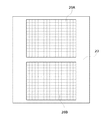
図1において、21は拡散性を有するピント板、22はペンタプリズム、23は使用者が被写体を観察する際に用いる接眼レンズ、24は第3の反射ミラー、25は集光レンズ、26は被写体の輝度に関する情報を得るための測光用センサーである。測光用センサー26は例えばシリコンフォトダイオード等の光電変換素子からなり、図3に示すように、格子状に複数の領域に分割された受光センサー部を有した構成になっており、撮影画面の略全域をカバーしている。図3に示したように、本実施の形態では受光センサー部を7列、5行からなる35分割された受光部で構成している。35分割された各受光部をそれぞれPD11〜PD17,PD21〜PD27,PD31〜PD37,PD41〜PD47,PD51〜PD57と呼ぶこととする。測光用センサー26は、信号増幅部や信号処理用の周辺回路などが受光センサー部と同一チップ上に形成された集積回路として構成されている。
In FIG. 1,
ピント板21、ペンタプリズム22、接眼レンズ23によってファインダー光学系が構成される。測光用センサー26には、主ミラー13によって反射されピント板21によって拡散された光線のうち、接眼レンズに到達する光線とは異なる光線の一部が入射する。測光用センサー26に入射する光線は交換レンズ装置30の明るさ(Fナンバー)や射出瞳の位置、ピント板21の拡散特性による影響を受けるため、測光用センサー26の出力信号は、これらの影響に依存する誤差が存在する。
The
図4は上述した焦点検出用センサー20等で構成された焦点検出手段により検出された撮影画面内の焦点検出位置と、35分割された図3の測光用センサー26との対応位置関係を表した図である。本実施の形態では撮影画面内の焦点検出位置をS01,S02,S03,S11,S12,S13,S21,S22,S23の9点としている。焦点検出位置S01は測光用センサー26の受光部PD23に対応した位置にて焦点検出を行い、焦点検出位置S02は測光用センサー26の受光部PD24に対応した位置にて焦点検出を行い、焦点検出位置S03は測光用センサー26の受光部PD25に対応した位置にて焦点検出を行い、焦点検出位置S11は測光用センサー26の受光部PD33に対応した位置にて焦点検出を行い、他の焦点検出位置もこれらと同様に測光用センサー26の受光部に対応した位置にて焦点検出を行う。
FIG. 4 shows the corresponding positional relationship between the focus detection position in the photographing screen detected by the focus detection means constituted by the above-described
図1において、27は交換レンズ装置30を取り付けるマウント部、28は交換レンズ装置30と情報通信を行うための接点部である。交換レンズ装置30は絞り31、カメラ本体10と情報通信を行うための接点部32、カメラ本体10に取り付けられるためのマウント部33、撮影レンズを構成する光学レンズ34〜38より構成されている。
In FIG. 1,
図5は図1におけるカメラ本体10と交換レンズ装置30の電気回路の構成例を表わすブロック図である。同図において、41は例えば内部にALU、ROM、RAMやA/Dコンバータ、タイマー、シリアル通信ポート(SPI)等を内蔵したワンチップマイクロコンピュータによるメイン制御回路であり、カメラ本体10と交換レンズ装置30からなるカメラシステムの全体の制御を行う。メイン制御回路41の具体的な制御シーケンスについては後述する。焦点検出用センサー20及び測光用センサー26の出力信号は、メイン制御回路41のA/Dコンバータ入力端子に接続される。尚、カメラの制御アルゴリズムを記載したプログラムコードはメモリ40に格納されており、メイン制御回路41がメモリ40からこのプログラムコードを読み出してカメラを制御している。
FIG. 5 is a block diagram showing a configuration example of an electric circuit of the
42はシャッター駆動装置でありメイン制御回路41の出力端子に接続されて、図1に記載のメカニカルシャッター11を駆動する。43は信号処理回路であり、メイン制御回路41の指示に従って撮像素子12を制御して撮像素子12が出力する撮像信号をA/D変換して信号処理を行い、画像信号を生成する。また、得られた画像信号に対して必要な画像処理を行う。44はフラッシュROM等の不揮発性メモリや光ディスク等による記憶媒体であり、得られた画像信号を記憶する。45は第1のモータードライバであり、メイン制御回路41に接続されて制御され、第1のモーター46を駆動して、主ミラー13及び第1の反射ミラー14を、交換レンズ装置30を通過した光線が撮像素子12に到達するように跳ね上げた第1の位置と、交換レンズ装置30を通過した光線が接眼レンズ23、測光用センサー26及び焦点検出用センサー20に到達するように下ろした第2の位置に切換える。47は被写体の輝度が不足した状態で撮影する時に発光するフラッシュ手段であり、メイン制御回路41の出力信号に応じて発光を行う。48は液晶パネル等で構成されて撮影枚数や日付情報、露出情報等を表示する表示器であり、やはりメイン制御回路41の出力信号に応じて表示を行うための各セグメントの点灯状態が制御される。49は各種のスイッチであり、撮像動作を開始するためのレリーズ釦等が含まれる。28は図1に記載した接点部であり、メイン制御回路41のシリアル通信ポートの入出力端子が接続される。
交換レンズ装置30側の構成要素を述べると、51は例えば内部にALU、ROM、RAMやタイマー、シリアル通信ポート(SPI)等を内蔵したワンチップマイクロコンピュータによるレンズ制御回路である。52は第2のモータードライバであり、レンズ制御回路51の出力端子に接続されて制御され、焦点調節を行うために第2のモーター53を駆動して撮影レンズ34〜38を移動させる。54は第3のモータードライバであり、レンズ制御回路51の出力端子に接続されて制御され、図1にて記載した絞り31の開閉動作を行うための第3のモーター55を駆動する。56は焦点調節レンズの繰り出し量、すなわち、被写体距離に関する情報を得るための距離エンコーダーであり、レンズ制御回路51の入力端子に接続される。57は交換レンズ30がズームレンズである場合に、撮影時の焦点距離情報を得るためのズームエンコーダーであり、レンズ制御回路51の入力端子に接続される。32は図1に記載した接点部であり、レンズ制御回路51のシリアル通信ポートの入出力端子が接続され、カメラ本体10側とその接点部28を介してデータの送受信を行う。
Describing the components on the
交換レンズ30がカメラ本体10に装着されると、それぞれの接点部28と32とが接続されてレンズ制御回路51はカメラ本体10のメイン制御回路41とのデータ通信が可能となる。カメラ本体10のメイン制御回路41が焦点検出や露出演算を行うために必要なレンズ固有の光学的な情報、距離エンコーダー56やズームエンコーダー57からの出力に基づいた被写体距離に関する情報、或いは、焦点距離情報等はレンズ制御回路51からカメラ本体10のメイン制御回路41へと送信される。また、カメラ本体10のメイン制御回路41が焦点検出や露出演算を行った結果求められた焦点調節情報や絞り情報は、カメラ本体10のメイン制御回路41からレンズ制御回路51へと送信され、レンズ制御回路51は得られた焦点調節情報に従って第2のモータードライバ52を制御するとともに、得られた絞り情報に従って第3のモータードライバ54を制御する。
When the
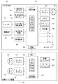
続いて図6のフローチャートに従ってカメラ本体10のメイン制御回路41によって指示される本実施の形態に係る具体的な撮像動作のシーケンスについて説明する。不図示の電源スイッチがオンされてメイン制御回路41が動作可能となり、レリーズ釦の第1ストロークスイッチがオンされると、図6のステップS101以下が実行される。
Next, a specific imaging operation sequence according to the present embodiment, which is instructed by the
メイン制御回路41が焦点検出用センサー20に対して制御信号を出力して、焦点検出用センサー20に信号蓄積を行わせる(ステップS101)。
The
焦点検出用センサー20に蓄積された信号を読み出しながらA/D変換させてデジタルデータを作成し、読み込まれた各デジタルデータに対してシェーディング等の必要な各種のデータ補正を行わせる(ステップS102)。
A / D conversion is performed while reading out the signal stored in the
焦点検出を行うために必要なレンズ情報等をレンズ制御回路51から取得し、取得したレンズ情報等と焦点検出用センサー20から得られたデジタルデータより、撮影画面各部の焦点状態を演算する(ステップS103)。得られた撮影画面各部の焦点状態より例えば特開平11−190816号公報等に記載されている手法によって、画面内の焦点を合わせるべき領域を決定する。なお、この焦点を合わせるべき領域の決定の仕方は周知であるため詳細な説明は省略する。そして、決定された領域における焦点状態に従って合焦となるためのレンズ移動量を算出する。
Lens information and the like necessary for focus detection are obtained from the
算出されたレンズ移動量をレンズ制御回路51に出力する(ステップS104)。これに従ってレンズ制御回路51は焦点調節用レンズを駆動するように第2のモータードライバ52に信号出力して、第2のモーター53を駆動する。これにより撮影レンズは被写体に対して合焦状態となる。
The calculated lens movement amount is output to the lens control circuit 51 (step S104). In accordance with this, the
測光用センサー26より35分割された各受光部PD11〜PD57の信号を読み出しながらA/D変換を行い画面各部の輝度情報を得る(ステップS105)。
A / D conversion is performed while reading out the signals of the light receiving units PD11 to PD57 divided into 35 by the
ステップS106では、必要なレンズ情報等をレンズ制御回路51から取得して、入力された画面各部の輝度情報の補正を行い、上記焦点を合わせる領域に対応した分割領域の輝度情報に重み付けをして画面全体の輝度を算出する。また、上記焦点を合わせる領域に対応した分割領域の輝度情報とそれ以外の画面周辺部分の輝度情報とを比較することにより逆光状態かどうかの判別を行い、逆光状態であると判別された場合には算出された画面全体の輝度を所定量だけ補正する。画面全体の輝度が所定値よりも低いといった条件の場合にはフラッシュ発光を行わせるよう設定する。このようにして算出された画面全体の輝度情報に基づいて、撮影に最適な撮像素子12の蓄積時間や出力増幅率、絞り値、或いは、シャッター速度等の露出量補償値を仮決定し表示器48に表示する。前述したように測光用センサー26の測光結果には若干の誤差があるが、このステップS106にて露出量補償値情報の表示が行われることで撮影者は被写界の輝度情報などを知ることが出来る。また、誤差については後のステップS113にて補正する。
In step S106, necessary lens information and the like are acquired from the
シャッター釦の第2ストロークスイッチがオンされるのを待つ(ステップS107)。オンされていなければ前記ステップS101に戻るが、もしも、オンされるとステップS108へ進む。 It waits until the second stroke switch of the shutter button is turned on (step S107). If it is not turned on, the process returns to step S101, but if it is turned on, the process proceeds to step S108.
ステップS108では、第1のモータードライバ45に制御信号を出力して、第1のモーター46を駆動して主ミラー13及び第1の反射ミラー14を跳ね上げる。
In step S108, a control signal is output to the
前記ステップS106にて演算された絞り値情報をレンズ制御回路51に対して出力する(ステップS109)。この情報に従ってレンズ制御回路51は絞り31を駆動するように第3のモータードライバ54に信号出力して、絞り31駆動用の第3のモーター55を駆動する。これにより撮影レンズは演算された絞り値に絞り込んだ状態となる。
The aperture value information calculated in step S106 is output to the lens control circuit 51 (step S109). According to this information, the
シャッター駆動装置42に対して信号出力を行い、シャッター11を開放状態とする(ステップS110)。これにより撮像素子12に撮影レンズを通過した光線が入射し、撮像可能状態となる。
A signal is output to the
前記ステップS106にて仮決定された露出量補償値の蓄積時間や出力増幅率にしたがって撮像素子12の蓄積時間や出力増幅率を設定し、該設定された蓄積時間や出力増幅率に基づいて露出量補償値の再演算用の第1の蓄積(撮像画像情報の蓄積)を撮像素子12によって行うように信号処理回路43に対して指示を出す(ステップS111)。
The accumulation time and the output amplification factor of the
第1の蓄積による撮像画像情報を撮像素子12からA/D変換しながら読み出して、必要な補正処理や信号処理を行うように信号処理回路43に対して指示を出す(ステップS112)。この第1の蓄積は露出量補償値を再演算するためのものなので、必ずしも撮像素子12の全画素に対応した情報を読み出す必要は無い。例えば総画素200万画素クラスの撮像素子であれば水平1600×垂直1200程度の画素数を有する訳であるが、読み出し時に画素間の信号の加算を行うとか読み出しラインの間引きなどを行って、読み出し情報量を減らして読み出し時間の短縮を行いつつ、最終的には図7に示すように撮像素子12の全画面の情報から測光用センサー26の35分割の各領域に対応するE11〜E57の輝度情報を得るように読み出し情報をグループ化すれば良い。
The image data obtained by the first accumulation is read out from the
得られた輝度情報E11〜E57に従って前記ステップS106と同様なアルゴリズムによる演算を行い画面全体の輝度情報を再度算出する(ステップS113)。撮像素子12に入射する光路にはピント板等は介在しないから輝度情報の誤差はなく正確な輝度情報が得られる。得られた輝度情報は既に絞りがステップS109で絞り込まれた上での輝度情報であるから、絞り31の絞り込み動作における誤差があったとしてもこの絞り状態に基づいて最適な露出量補償値となるような蓄積時間を求めることで誤差を吸収できる。
According to the obtained luminance information E11 to E57, an operation is performed by the same algorithm as in step S106, and the luminance information of the entire screen is calculated again (step S113). Since no focus plate or the like is interposed in the optical path incident on the
前記ステップS113にて再演算された露出量補償値の蓄積時間や出力増幅率にしたがって撮像素子12の蓄積時間や出力増幅率を設定して、該設定された蓄積時間や出力増幅率に基づいて第2の蓄積を撮像素子12によって行うように信号処理回路43に対して指示を出す(ステップS114)。また、露出量補償値演算によってフラッシュ手段47を使用して撮影すべきシーンであると判別されている場合にはフラッシュ手段47を発光させる。
The accumulation time and output amplification factor of the
シャッター駆動装置42に対して信号出力を行い、シャッター11を遮光状態とする(ステップS115)。これにより撮像素子12に対する撮影レンズからの光線が遮断される。
A signal is output to the
レンズ制御回路51に対して絞り31を開放するように情報出力する(ステップS116)。この情報に従ってレンズ制御回路51は絞り31を駆動するように第3のモータードライバ54に信号出力して、第3のモーター55を駆動する。これにより撮影レンズは絞り開放状態となる。
Information is output to the
第1のモータードライバ54に制御信号を出力して、第1のモーター46を駆動して主ミラー13及び第1の反射ミラー14をダウンさせる(ステップS117)。
A control signal is output to the
第2の蓄積による撮像画像情報を撮像素子12からA/D変換しながら読み出して、必要な補正処理や信号処理を行うように信号処理回路43に対して指示を出す(ステップS118)。さらに、撮像画像情報を記録ファイルフォーマットに変換して記憶手段44に記憶するように信号処理回路43に対して指示を出す。
The image data obtained by the second accumulation is read out from the
これで一連の撮影シーケンスが終了する。 This completes a series of photographing sequences.
次に、本発明の第2の実施の形態について説明する。 Next, a second embodiment of the present invention will be described.
本第2の実施の形態に係るカメラは、上述の第1の実施の形態に係るカメラに対して、図1から図5に示したカメラの構成と全く同様であり、撮影シーケンスのみが相違する。図8は、本発明の第2の実施の形態に係る撮像装置としてのカメラの制御回路が実行する動作フローチャートである。 The camera according to the second embodiment is completely the same as the camera according to the above-described first embodiment in the configuration of the camera shown in FIGS. 1 to 5, except for the photographing sequence. . FIG. 8 is an operation flowchart executed by a control circuit of a camera as an imaging device according to the second embodiment of the present invention.
本第2の実施の形態に係るカメラにおいて、不図示の電源スイッチがオンされてメイン制御回路41が動作可能となり、不図示のレリーズ釦の第1ストロークスイッチがオンされると、図8のステップS201より以下の撮影シーケンスが実行される。
In the camera according to the second embodiment, when a power switch (not shown) is turned on to enable the
焦点検出用センサー20に対して制御信号を出力して、焦点検出用センサー20に信号蓄積を行わせる(ステップS201)。
A control signal is output to the
焦点検出用センサー20に蓄積された信号を読み出しながらA/D変換させてデジタルデータを作成し、読み込まれた各デジタルデータに対してシェーディング等の必要な各種のデータ補正を行わせる(ステップS202)。
A / D conversion is performed while reading out the signal accumulated in the
焦点検出を行うために必要なレンズ情報等をレンズ制御回路51から取得し、取得したレンズ情報等と焦点検出用センサー20から得られたデジタルデータより撮影画面各部の焦点状態を演算する(ステップS203)。得られた撮影画面各部の焦点状態より上記第1の実施の形態と同様の手法により画面内の焦点を合わせるべき領域を決定する。決定された領域における焦点状態に従って合焦となるためのレンズ移動量を算出する。
Lens information and the like necessary for performing focus detection are obtained from the
算出されたレンズ移動量をレンズ制御回路51に出力する(ステップS204)。これに従ってレンズ制御回路51は焦点調節用レンズを駆動するように第2のモータードライバ52に信号出力して、第2のモーター53を駆動する。これにより撮影レンズは被写体に対して合焦状態となる。
The calculated lens movement amount is output to the lens control circuit 51 (step S204). In accordance with this, the
測光用センサー26より35分割された各受光部PD11〜PD57の信号を読み出しながらA/D変換を行い画面各部の輝度情報を得る(ステップS205)。
A / D conversion is performed while reading out the signals of the light receiving units PD11 to PD57 divided into 35 by the
ステップS206では、必要なレンズ情報等をレンズ制御回路51より入力して、入力された画面各部の輝度情報の補正を行い、上記焦点を合わせるべき領域に対応した分割領域の輝度情報に重み付けをして画面全体の輝度を算出する。また、上記焦点を合わせるべき領域に対応した分割領域の輝度情報とそれ以外の画面周辺部分の輝度情報とを比較することにより逆光状態かどうかの判別を行い、逆光状態であると判別された場合には算出された画面全体の輝度を所定量だけ補正する。画面全体の輝度が所定値よりも低いといった条件の場合にはフラッシュ発光を行わせるよう設定する。このようにして算出された画面全体の輝度情報に基づいて、絞り値を除いた撮影に最適な撮像素子12の蓄積時間や出力増幅率等、或いは、シャッター速度等の露出量補償値を仮決定し表示器48に表示する。前述したように測光用センサー26の測光結果には若干の誤差があるが、このステップS206にて露出量補償値情報の表示が行われることで撮影者は被写界の輝度情報などを知ることが出来る。また、誤差については後のステップS214にて補正する。
In step S206, necessary lens information and the like are input from the
シャッター釦の第2ストロークスイッチがオンされるのを待つ(ステップS207)。オンされていなければ前記ステップS201に戻るが、もしも、オンされるとステップS208へ進む。 It waits until the second stroke switch of the shutter button is turned on (step S207). If the switch is not turned on, the process returns to step S201. If the switch is turned on, the process proceeds to step S208.
ステップS208では、第1のモータードライバ45に制御信号を出力して、第1のモーター46を駆動して主ミラー13及び第1の反射ミラー14を跳ね上げる。
In step S208, a control signal is output to the
シャッター駆動装置42に対して信号出力を行い、シャッター11を開放状態とする(ステップS209)。これにより撮像素子12に撮影レンズからの光線が入射し、撮像可能状態となる。なお、本実施の形態では、この時点では絞り値情報をレンズ制御回路51に対して出力していない。絞り値は初期値として開放状態に設定されており、本実施の形態では絞り値を開放状態に固定したまま第1の蓄積を行う。
A signal is output to the
前記ステップS206にて仮決定された露出量補償値の蓄積時間や出力増幅率にしたがって撮像素子12の蓄積時間や出力増幅率を設定し、該設定された蓄積時間や出力増幅率に基づいて露出量補償値の再演算用の第1の蓄積を撮像素子12によって行うように信号処理回路43に対して指示を出す(ステップS210)。
The storage time and output gain of the
第1の蓄積による撮像画像情報を撮像素子12からA/D変換しながら読み出して、必要な補正処理や信号処理を行うように信号処理回路43に対して指示を出す(ステップS211)。この第1の蓄積は露出量補償値を再演算するためのものなので、必ずしも撮像素子12の全画素に対応した情報を読み出す必要は無い。例えば総画素200万画素クラスの撮像素子であれば水平1600×垂直1200程度の画素数を有する訳であるが、読み出し時に画素間の信号の加算を行うとか読み出しラインの間引きなどを行って、読み出し情報量を減らして読み出し時間の短縮を行いつつ、最終的には図7に示すように撮像素子12の全画面の情報から測光用センサー26の35分割の各領域に対応するE11〜E57の輝度情報を得るように読み出し情報をグループ化すれば良い。
The captured image information obtained by the first accumulation is read out from the
得られた輝度情報E11〜E57に従って前記ステップS206と同様なアルゴリズムによる演算を行い画面全体の輝度情報を再度算出する(ステップS212)。撮像素子12に入射する光路にはピント板等は介在しないから輝度情報の誤差はなく正確な輝度情報が得られる。第1の実施の形態とは異なって得られた輝度情報は絞りが開放状態での輝度情報であるから、絞り31の絞り込み動作における誤差は吸収できないが、逆に正確な輝度情報に基づいて本撮像用の最適な絞り値をこのステップS212で決定できるメリットがある。
According to the obtained luminance information E11 to E57, a calculation is performed by the same algorithm as in step S206, and the luminance information of the entire screen is calculated again (step S212). Since no focus plate or the like is interposed in the optical path incident on the
前記ステップS206にて演算された絞り値情報をレンズ制御回路51に対して出力する(ステップS213)。この情報に従ってレンズ制御回路51は絞り31を駆動するように第3のモータードライバ54に信号出力して、第3のモーター55を駆動する。これにより撮影レンズは演算された絞り値に絞り込まれた状態となる。
The aperture value information calculated in step S206 is output to the lens control circuit 51 (step S213). According to this information, the
前記ステップS212にて再演算された蓄積時間や出力増幅率にしたがって撮像素子12の蓄積時間や出力増幅率を設定して、該設定された蓄積時間や出力増幅率に基づいて第2の蓄積を撮像素子12によって行うように信号処理回路43に対して指示を出す(ステップS214)。また、露出量補償値演算によってフラッシュ手段47を使用して撮影すべきシーンであると判別されている場合にはフラッシュ手段47を発光させる。
The accumulation time and the output amplification factor of the
シャッター駆動装置42に対して信号出力を行い、シャッター11を遮光状態とする(ステップS215)。これにより撮像素子12に対する撮影レンズからの光線が遮断される。
A signal is output to the
レンズ制御回路51に対して絞り31を開放するように情報出力する(ステップS216)。この情報に従ってレンズ制御回路51は絞り31を駆動するように第3のモータードライバ54に信号出力して、第3のモーター55を駆動する。これにより撮影レンズは絞り開放状態となる。
Information is output to the
第1のモータードライバ45に制御信号を出力して、第1のモーター46を駆動して主ミラー13及び第1の反射ミラー14をダウンさせる(ステップS217)。
A control signal is output to the
第2の蓄積による撮像画像情報を撮像素子12からA/D変換しながら読み出して、必要な補正処理や信号処理を行うように信号処理回路43に対して指示を出す(ステップS218)。さらに、撮像画像情報を記録ファイルフォーマットに変換して記憶手段44に記憶するように信号処理回路43に対して指示を出す。
The image data obtained by the second accumulation is read out from the
これで一連の撮影シーケンスが終了する。 This completes a series of photographing sequences.
以上説明したように、上記第1及び第2の実施の形態によれば、個々の交換レンズ装置30の特性に起因する誤差や、カメラ本体10内の個々の光学部材の特性に起因する誤差を包含した上で露出量補償値を仮に設定して第1の蓄積を行い、この第1の蓄積結果を用いて露出量補償値を再設定することで、前記の誤差を全て帳消しにした露出量補償値を設定することが可能となる。
As described above, according to the first and second embodiments, errors caused by the characteristics of the individual
つまり、交換レンズ装置10の個々の特性によって画面の中央付近とその周辺付近の光量バランスに差異が生じても、その影響を防止することができる。
In other words, even if there is a difference in light amount balance between the vicinity of the center of the screen and the vicinity of the periphery due to individual characteristics of the
また、撮像素子とは別の光路上に配置されたピント板等の光学部材の特性にバラツキがあったとしても、その影響を防止することができる。 Further, even if the characteristics of optical members such as a focus plate arranged on an optical path different from that of the image pickup device vary, the influence can be prevented.
なお、本発明の目的は、カメラ本体10、或いは、カメラ本体10に接続されてこのカメラ本体10を制御するためのコマンドをこのカメラ本体10に供給するカメラ制御装置等に、上記の各実施の形態の機能を実現するためのソフトウェアのプログラムコードを記憶した記憶媒体を供給し、そのカメラ本体10、或いは、カメラ制御装置のコンピュータに記憶媒体に格納されたプログラムコードを読み出して実行させることによっても達成される。
An object of the present invention is to provide the
この場合、記憶媒体から読み出されたプログラムコード自体が前述した実施の形態の機能を実現することになり、そのプログラムコードを記憶した記憶媒体は本発明を構成することになる。 In this case, the program code itself read from the storage medium realizes the functions of the above-described embodiment, and the storage medium storing the program code constitutes the present invention.
プログラムコードを供給するための記憶媒体としては、例えば、RAM、フロッピー(登録商標)ディスク、ハードディスク、光ディスク、光磁気ディスク、CD−ROM、CD−RW、DVD−ROM、DVD−RAM、DVD−RW、DVD+RW、磁気テープ、不揮発性のメモリカード、ROM、EEPROM等を用いることができる。又は、プログラムコードをネットワークを介してダウンロードしてもよい。 Examples of a storage medium for supplying the program code include a RAM, a floppy (registered trademark) disk, a hard disk, an optical disk, a magneto-optical disk, a CD-ROM, a CD-RW, a DVD-ROM, a DVD-RAM, and a DVD-RW. , DVD + RW, magnetic tape, non-volatile memory card, ROM, EEPROM, and the like. Alternatively, the program code may be downloaded via a network.
また、コンピュータが読み出したプログラムコードを実行することにより、上記実施の形態の機能が実現されるだけでなく、そのプログラムコードの指示に基づき、コンピュータ上で稼動しているOS(オペレーティングシステム)等が実際の処理の一部または全部を行い、その処理によって前述した実施の形態の機能が実現される場合も含まれることはいうまでもない。 When the computer executes the readout program code, not only the functions of the above-described embodiment are realized, but also an OS (Operating System) running on the computer based on the instruction of the program code. It goes without saying that a case where some or all of the actual processing is performed and the functions of the above-described embodiments are realized by the processing is also included.
更に、記憶媒体から読み出されたプログラムコードが、コンピュータに挿入された機能拡張ボードやコンピュータに接続された機能拡張ユニットに備わるメモリに書き込まれた後、そのプログラムコードの指示に基づき、その機能拡張ボードや機能拡張ユニットに備わるCPU等が実際の処理の一部または全部を行い、その処理によって前述した実施の形態の機能が実現される場合も含まれることはいうまでもない。 Further, after the program code read from the storage medium is written into a memory provided in a function expansion board inserted into the computer or a function expansion unit connected to the computer, the function expansion is performed based on the instruction of the program code. It goes without saying that a CPU or the like provided in the board or the function expansion unit performs part or all of the actual processing, and the processing realizes the functions of the above-described embodiments.
10 カメラ本体
11 メカニカルシャッター
12 撮像素子
13 主ミラー
20 焦点検出用センサー
21 ピント板
26 測光用センサー
30 交換レンズ
31 絞り
41 カメラの制御手段
43 信号処理回路
51 交換レンズの制御手段
Claims (11)
前記制御手段は、前記測光手段の出力する輝度情報に基づいて第1の露出量補償値を設定し、該第1の露出量補償値に基づいて前記撮像素子に前記通過した光の第1の蓄積を行わせ、前記第1の蓄積結果に基づいて第2の露出量補償値を設定し、該第2の露出量補償値に基づいて前記撮像素子に前記通過した光の第2の蓄積を行わせることを特徴とする撮像装置。 An image sensor that outputs an image signal in response to light that has passed through a photographic lens attached to a main body, a photometer that outputs luminance information in response to light that has passed through the photographic lens, and according to an output of the photometer. An imaging device comprising: a control unit for setting an exposure compensation value;
The control unit sets a first exposure compensation value based on luminance information output from the photometric unit, and sets a first exposure compensation value of the light that has passed through the image sensor based on the first exposure compensation value. Accumulation is performed, a second exposure compensation value is set based on the first accumulation result, and a second accumulation of the passed light is stored in the image sensor based on the second exposure compensation value. An imaging device characterized in that the imaging is performed.
前記制御手段は、前記測光手段の出力する輝度情報に基づいて第1の露出量補償値を設定し、該第1の露出量補償値に基づいて前記撮像素子に前記通過した光の第1の蓄積を行わせ、前記第1の蓄積結果に基づいて第2の露出量補償値を設定し、該第2の露出量補償値に基づいて前記撮像素子に前記通過した光の第2の蓄積を行わせることを特徴とする撮像装置。 An image sensor that outputs an image signal by receiving light that has passed through a photographic lens; a photometric unit that is disposed at a different position from the image sensor and that outputs luminance information by receiving light that has passed through the photographic lens; A mirror member disposed between the lens and the image sensor so as to be able to advance and retreat, and a mirror member capable of reflecting light passing through the photographing lens in a direction different from that of the image sensor, and disposed between the photometric unit and the mirror member; An optical member that guides light reflected by a mirror member to the photometric unit, and an imaging device that includes a control unit that sets an exposure compensation value of the imaging element according to an output of the photometric unit.
The control unit sets a first exposure compensation value based on luminance information output from the photometric unit, and sets a first exposure compensation value of the light that has passed through the image sensor based on the first exposure compensation value. Accumulation is performed, a second exposure compensation value is set based on the first accumulation result, and a second accumulation of the passed light is stored in the image sensor based on the second exposure compensation value. An imaging device characterized in that the imaging is performed.
前記測光手段によって被写界の輝度情報を求め、前記求められた輝度情報に基づいて第1の露出量補償値を設定し、該第1の露出量補償値に基づいて前記撮像素子に前記通過した光の第1の蓄積を行わせ、前記第1の蓄積結果に基づいて第2の露出量補償値を設定し、該第2の露出量補償値に基づいて前記撮像素子に前記通過した光の第2の蓄積を行わせることを特徴とする制御方法。 An image sensor that outputs an image signal by receiving light that has passed through a photographic lens, and a control method of an image capturing apparatus that includes a photometer that outputs luminance information by receiving light that has passed through the photographic lens,
The luminance information of the object scene is obtained by the photometric means, a first exposure compensation value is set based on the obtained luminance information, and the first exposure compensation value is passed to the image sensor based on the first exposure compensation value. The first light is stored, a second exposure compensation value is set based on the first accumulation result, and the light that has passed through the image sensor based on the second exposure compensation value is set. A second storage method.
前記測光手段によって被写界の輝度情報を求め、前記求められた輝度情報に基づいて第1の露出量補償値を設定し、該第1の露出量補償値に基づいて前記撮像素子に前記通過した光の第1の蓄積を行わせ、前記第1の蓄積結果に基づいて第2の露出量補償値を設定し、該第2の露出量補償値に基づいて前記撮像素子に前記通過した光の第2の蓄積を行わせることを特徴とする制御方法。 In a control method of an imaging device capable of switching light that has passed through a photographing lens to a state in which the light reaches a photometric unit arranged separately from an imaging element and a state in which the light does not reach,
The luminance information of the object scene is obtained by the photometric means, a first exposure compensation value is set based on the obtained luminance information, and the first exposure compensation value is passed to the image sensor based on the first exposure compensation value. The first light is stored, a second exposure compensation value is set based on the first accumulation result, and the light that has passed through the image sensor based on the second exposure compensation value is set. A second storage method.
前記測光手段により被写界の輝度情報を求めさせる測光モジュールと、前記求められた輝度情報に基づいて第1の露出量補償値を設定して前記撮像素子に前記通過した光の第1の蓄積を行わせる第1の蓄積モジュールと、前記第1の蓄積結果に基づいて第2の露出量補償値を設定して前記撮像素子に前記通過した光の第2の蓄積を行わせる第2の蓄積モジュールとを備えることを特徴とする記憶媒体。 An image pickup device readable by a computer, comprising: an image sensor that outputs an image signal in response to light passing through a photographing lens; and a photometer that outputs luminance information in response to light passing through the photographing lens. In a storage medium storing a program for executing control,
A photometric module for obtaining luminance information of a field by the photometric means; a first exposure compensation value set based on the obtained luminance information, and a first accumulation of the light having passed through the image sensor; And a second accumulation unit that sets a second exposure compensation value based on the first accumulation result and causes the image sensor to perform a second accumulation of the light that has passed therethrough. A storage medium comprising a module.
前記測光手段により被写界の輝度情報を求めさせる測光モジュールと、前記求められた輝度情報に基づいて第1の露出量補償値を設定して前記撮像素子に前記通過する光の第1の蓄積を行わせる第1の蓄積モジュールと、前記第1の蓄積結果に基づいて第2の露出量補償値を設定して前記撮像素子に前記通過した光の第2の蓄積を行わせる第2の蓄積モジュールとを備えることを特徴とする記憶媒体。 Imaging that is readable by a computer and can be switched between a state in which light that has passed through an imaging lens reaches an image sensor and a state in which light reaches a photometric unit that is arranged separately from the image sensor via an optical member. In a storage medium storing a program for executing control of the device,
A photometric module for obtaining luminance information of the object scene by the photometric means; a first exposure compensation value set based on the obtained luminance information, and a first accumulation of the passing light in the image sensor; And a second accumulation unit that sets a second exposure compensation value based on the first accumulation result and causes the image sensor to perform a second accumulation of the light that has passed therethrough. A storage medium comprising a module.
Priority Applications (2)
| Application Number | Priority Date | Filing Date | Title |
|---|---|---|---|
| US10/715,922 US7359000B2 (en) | 2002-11-18 | 2003-11-18 | Image pickup apparatus, control method therefor, and computer-readable program for implementing the control method |
| JP2003388415A JP2004187287A (en) | 2002-11-18 | 2003-11-18 | Image pickup device, control method for the image pickup device, and recording medium stored with computer-readable program executing the control method |
Applications Claiming Priority (2)
| Application Number | Priority Date | Filing Date | Title |
|---|---|---|---|
| JP2002333548 | 2002-11-18 | ||
| JP2003388415A JP2004187287A (en) | 2002-11-18 | 2003-11-18 | Image pickup device, control method for the image pickup device, and recording medium stored with computer-readable program executing the control method |
Publications (2)
| Publication Number | Publication Date |
|---|---|
| JP2004187287A true JP2004187287A (en) | 2004-07-02 |
| JP2004187287A5 JP2004187287A5 (en) | 2006-12-07 |
Family
ID=32774568
Family Applications (1)
| Application Number | Title | Priority Date | Filing Date |
|---|---|---|---|
| JP2003388415A Pending JP2004187287A (en) | 2002-11-18 | 2003-11-18 | Image pickup device, control method for the image pickup device, and recording medium stored with computer-readable program executing the control method |
Country Status (2)
| Country | Link |
|---|---|
| US (1) | US7359000B2 (en) |
| JP (1) | JP2004187287A (en) |
Cited By (2)
| Publication number | Priority date | Publication date | Assignee | Title |
|---|---|---|---|---|
| JP2006208897A (en) * | 2005-01-31 | 2006-08-10 | Canon Inc | Lens system |
| CN112565620A (en) * | 2020-11-26 | 2021-03-26 | 京东方科技集团股份有限公司 | Optical compensation method and device for display screen, storage medium and electronic equipment |
Families Citing this family (2)
| Publication number | Priority date | Publication date | Assignee | Title |
|---|---|---|---|---|
| JP2011197470A (en) * | 2010-03-19 | 2011-10-06 | Panasonic Corp | Zoom lens system, interchangeable lens device, and camera system |
| JP5822508B2 (en) * | 2011-04-05 | 2015-11-24 | キヤノン株式会社 | Imaging apparatus and control method thereof |
Family Cites Families (9)
| Publication number | Priority date | Publication date | Assignee | Title |
|---|---|---|---|---|
| GB2219461B (en) * | 1988-05-02 | 1992-11-18 | Canon Kk | Exposure control device |
| US5218442A (en) * | 1989-12-21 | 1993-06-08 | Minolta Camera Kabushiki Kaisha | Camera with camera-shake detection apparatus |
| JP2899031B2 (en) * | 1989-12-28 | 1999-06-02 | キヤノン株式会社 | Automatic exposure control device |
| JPH06265966A (en) * | 1993-03-12 | 1994-09-22 | Nikon Corp | Photometry device for camera |
| JP3427454B2 (en) * | 1993-12-21 | 2003-07-14 | 株式会社ニコン | Still camera |
| JP2001036806A (en) * | 1999-07-16 | 2001-02-09 | Asahi Optical Co Ltd | Exposure controller for electronic camera |
| US6906744B1 (en) * | 1999-09-28 | 2005-06-14 | Nikon Corporation | Electronic camera |
| JP4882159B2 (en) * | 2001-04-18 | 2012-02-22 | 株式会社ニコン | Flash control device and camera system |
| US7576797B2 (en) * | 2001-06-25 | 2009-08-18 | Texas Instruments Incorporated | Automatic white balancing via illuminant scoring autoexposure by neural network mapping |
-
2003
- 2003-11-18 JP JP2003388415A patent/JP2004187287A/en active Pending
- 2003-11-18 US US10/715,922 patent/US7359000B2/en not_active Expired - Fee Related
Cited By (3)
| Publication number | Priority date | Publication date | Assignee | Title |
|---|---|---|---|---|
| JP2006208897A (en) * | 2005-01-31 | 2006-08-10 | Canon Inc | Lens system |
| CN112565620A (en) * | 2020-11-26 | 2021-03-26 | 京东方科技集团股份有限公司 | Optical compensation method and device for display screen, storage medium and electronic equipment |
| US11668995B2 (en) | 2020-11-26 | 2023-06-06 | Chengdu Boe Optoelectronics Technology Co., Ltd. | Optical compensation method for display screen, storage medium, and electronic device |
Also Published As
| Publication number | Publication date |
|---|---|
| US20040151488A1 (en) | 2004-08-05 |
| US7359000B2 (en) | 2008-04-15 |
Similar Documents
| Publication | Publication Date | Title |
|---|---|---|
| US7006140B2 (en) | Digital still camera with shifting focus lens | |
| US6816199B1 (en) | Focus detecting device | |
| JP2008187615A (en) | Imaging device, imaging apparatus, control method, and program | |
| JP2008191335A (en) | Imaging apparatus and imaging system | |
| JP2000162494A (en) | Electronic camera | |
| JP2011002848A (en) | Imaging device | |
| JP2010113272A (en) | Imaging apparatus | |
| JP2000155256A (en) | Interchangeable photographing lens device, camera body and camera system | |
| JP2000324377A (en) | Electronic image pickup unit | |
| JP2004187287A (en) | Image pickup device, control method for the image pickup device, and recording medium stored with computer-readable program executing the control method | |
| JP2003158666A (en) | Electronic image pickup unit of interchangeable lens type and electronic image pickup system | |
| JPH11142723A (en) | Image pickup device | |
| JP2007171298A (en) | Imaging apparatus, and its control method, program and storage medium therefor | |
| JP2007251656A (en) | Image sensing device, its control method and program | |
| JP4593900B2 (en) | IMAGING DEVICE, ITS CONTROL METHOD, PROGRAM, AND STORAGE MEDIUM | |
| JP2006119454A (en) | Imaging apparatus and photometry method for imaging apparatus | |
| JP2000131595A (en) | Camera and focusing device | |
| JP2006003533A (en) | Imaging apparatus, focusing control method and program | |
| JP2000032323A (en) | Electronic camera | |
| JP2004179963A (en) | Imaging device | |
| JP2011175172A (en) | Digital camera | |
| JP2007036983A (en) | Digital camera with exchangeable lens | |
| JP2004239965A (en) | Focusing device, camera and focusing program, and recording medium with the program recorded thereto | |
| JP2008203407A (en) | Imaging apparatus, lens device and imaging system | |
| JP2004272241A (en) | Focus detecting device |
Legal Events
| Date | Code | Title | Description |
|---|---|---|---|
| A521 | Request for written amendment filed |
Free format text: JAPANESE INTERMEDIATE CODE: A523 Effective date: 20040518 |
|
| RD03 | Notification of appointment of power of attorney |
Free format text: JAPANESE INTERMEDIATE CODE: A7423 Effective date: 20060418 |
|
| A521 | Request for written amendment filed |
Free format text: JAPANESE INTERMEDIATE CODE: A523 Effective date: 20061025 |
|
| A621 | Written request for application examination |
Free format text: JAPANESE INTERMEDIATE CODE: A621 Effective date: 20061025 |
|
| RD05 | Notification of revocation of power of attorney |
Free format text: JAPANESE INTERMEDIATE CODE: A7425 Effective date: 20070626 |
|
| A131 | Notification of reasons for refusal |
Free format text: JAPANESE INTERMEDIATE CODE: A131 Effective date: 20090324 |
|
| A521 | Request for written amendment filed |
Free format text: JAPANESE INTERMEDIATE CODE: A523 Effective date: 20090519 |
|
| A02 | Decision of refusal |
Free format text: JAPANESE INTERMEDIATE CODE: A02 Effective date: 20090609 |