JP2004180260A - Signal converting apparatus - Google Patents
Signal converting apparatus Download PDFInfo
- Publication number
- JP2004180260A JP2004180260A JP2003074943A JP2003074943A JP2004180260A JP 2004180260 A JP2004180260 A JP 2004180260A JP 2003074943 A JP2003074943 A JP 2003074943A JP 2003074943 A JP2003074943 A JP 2003074943A JP 2004180260 A JP2004180260 A JP 2004180260A
- Authority
- JP
- Japan
- Prior art keywords
- signal
- unit
- state
- control signal
- communication function
- Prior art date
- Legal status (The legal status is an assumption and is not a legal conclusion. Google has not performed a legal analysis and makes no representation as to the accuracy of the status listed.)
- Pending
Links
Images


Landscapes
- Circuits Of Receivers In General (AREA)
- Telephonic Communication Services (AREA)
- Selective Calling Equipment (AREA)
Abstract
Description
【0001】
【発明の属する技術分野】
本発明は信号変換技術に関し、とくに有線や無線を利用したネットワークにおける装置間の信号を変換する装置に関する。
【0002】
【従来の技術】
インターネットに見られるように、コンピュータのネットワーク化は着実に進んでいる。ADSL、光ファイバ等のインフラをはじめとするネットワーク環境が整うにつれて、インターネットは人々の生活の一部として浸透し始めている。こうした中、家庭内の電化製品もネットワークに組み込み、省エネルギー、ホームヘルスケアを目指したホームネットワークを構築する試みが各所で行われている。
【0003】
有線や無線を利用した通信技術は、そうしたホームネットワークには欠かすことのできないものである。例えば、家電間のネットワーク技術を標準化する団体が存在し、そこでは、ホームネットワークに接続した機器間の双方向通信方式や、制御方式等の標準化を進めている。
【0004】
この標準化規格は、例えば、制御対象機器との接続の形式、動作命令の形式、その機器からの通知情報の形式などを決めている。この規格に基づいた機器によれば、例えば、ユーザが外出先から電話等の端末を使って、自宅にある機器を遠隔操作することができる。
【0005】
【発明が解決しようとする課題】
ホームネットワークを構築するためには、例えばその標準規格を満たす機器が必要になる。このため、ユーザはホームネットワークに対応する機器を新たに購入する必要がある。
【0006】
本発明者はこうした現状に着目して本発明をなしたものであり、その目的は、ネットワーク接続機能を有しない機器をホームネットワークに取り込む技術を提供することにある。また、別の目的は、そうした機能を実現する装置を提供することにある。更に別の目的は、ホームネットワークへの移行をスムーズに進めるための技術を提供することにある。
【0007】
【課題を解決するための手段】
本発明のある態様は、信号変換装置である。この装置は、ネットワークを利用した双方向通信機能を有する第1装置を制御するための第1制御信号を、前記ネットワークを介して受信する受信部と、前記第1制御信号を、前記第1制御信号を認識できない第2装置を制御するための第2制御信号に変換する変換部と、前記双方向通信機能とは異なる単方向通信機能を利用して前記第2制御信号を前記第2装置に送信する送信部とを備える。「第1装置」は、例えば前述した標準化規格を満たす装置であり、「第2装置」は、標準化規格を満たさない従来の装置である。「単方向通信機能」は、例えば「赤外線リモコン」として利用されている、赤外線を使った通信機能である。「ネットワーク」は、電話線、電灯線、イーサネット(登録商標)等の有線LAN、およびPHS(登録商標)、Bluetooth(登録商標)、IEEE802.11規格等の無線LANを含む。
【0008】
本発明の別の態様も、信号変換装置である。この装置は、双方向通信機能を有する第1装置を制御するための第1制御信号を受信する受信部と、前記第1制御信号を、単方向通信機能を有する第2装置を制御するための第2制御信号に変換する変換部と、前記第2制御信号を前記第2装置に送信する送信部と、前記第2装置の周辺の環境状態に基づいて、前記第2装置の動作状態を推定する推定部とを備える。「環境状態」は、例えば温度、湿度、音量、明暗などの状態である。
【0009】
この装置は、前記第2装置の周辺の環境状態を検出する複数の種類のセンサを更に備え、前記変換部は、前記第2制御信号を受信した前記第2装置がすべき動作により変化が生じる環境要素の状態を検出するためのセンサを前記推定部に指示し、前記推定部は、指示されたセンサが検出した環境状態に基づいて動作状態を推定してもよい。「センサ」は広義に用い、例えば、温度センサ、湿度センサ、CCDカメラ、マイクなどである。「環境要素」は、例えば、温度、湿度、音量など環境を決定する個々の要因をいい、その環境要素ごとに、状態を検出するためのセンサが決められている。
【0010】
本発明のさらに別の態様も、信号変換装置である。この装置は、双方向通信機能を有する所定の装置から、その装置の動作状態を示す第1状態信号を受信する受信部と、前記所定の装置の周辺の環境状態を検出するセンサからの信号に基づいて、前記所定の装置の動作状態を推定し第2状態信号を出力する推定部と、前記第1状態信号と前記第2状態信号のいずれか一方を、その信号を必要とする装置に出力する状態提供部とを備える。「動作状態」は、例えば、「運転中」、「停止中」などのその機器の運転状態である。
【0011】
前記状態提供部は、前記第1状態信号と前記第2状態信号とが同一の動作状態を示しているか否かを判定する判定部と、前記第1状態信号と前記第2状態信号とが異なる動作状態を示す場合に、優先して出力すべき一方の状態信号を設定する優先信号設定部とを有してもよい。
【0012】
本発明のさらに別の態様も、信号変換装置である。この装置は、双方向通信機能を有する第1装置を制御するための第1制御信号を受信する第1受信部と、前記第1制御信号を、単方向通信機能を有する第2装置を制御するための第2制御信号に変換する変換部と、前記第2制御信号を前記第2装置に送信する送信部と、前記第2装置に着脱可能に装着された第3装置から、前記第2制御信号を受信したことを指示する信号を受信する第2受信部とを備える。第1受信部と第2受信部とは、同一の受信ユニットであってもよい。
【0013】
本発明のさらに別の態様も、信号変換装置である。この装置は、双方向通信機能を有する第1装置を制御するための第1制御信号を受信する第1受信部と、前記第1制御信号を、単方向通信機能を有する第2装置を制御するための第2制御信号に変換する変換部と、前記第2制御信号を前記第2装置に送信する送信部と、前記第2装置に着脱可能に装着された第3装置から、前記第2装置に流入する電流量に基づいて生成した信号を受信する第2受信部とを備える。
【0014】
本発明のさらに別の態様も、信号変換装置である。この装置は、双方向通信機能を有する所定の装置から、その装置の動作状態を示す第1状態信号を受信する受信部と、前記所定の装置に流入する電流量を検出するセンサからの信号に基づいて、前記所定の装置の動作状態を推定し第2状態信号を出力する推定部と、前記第1状態信号と前記第2状態信号のいずれか一方を、その信号を必要とする装置に出力する状態提供部とを備える。
【0015】
本発明のさらに別の態様も、信号変換装置である。この装置は、双方向通信機能を有する所定の装置から、その装置の動作状態を示す第1状態信号を受信する受信部と、前記所定の装置の周辺の環境状態を検出する第1センサからの信号と、前記所定の装置に流入する電流量を検出する第2センサからの信号とに基づいて、前記所定の装置の動作状態を推定し第2状態信号を出力する推定部と、前記第1状態信号と前記第2状態信号のいずれか一方を、その信号を必要とする装置に出力する状態提供部とを備える。また、前記第2センサは、前記所定の装置に着脱可能に装着されてもよい。
【0016】
なお、以上の構成要素の任意の組合せ、本発明の表現を方法、装置、システム、記録媒体、コンピュータプログラムなどの間で変換したものもまた、本発明の態様として有効である。
【0017】
【発明の実施の形態】
<第1の実施形態>
図1は、第1の実施形態における家電制御システム10の構成図である。ホームネットワーク50は、例えば電話線、電灯線などのネットワーク22を利用して信号の伝送を行い機器の制御を行うことができる。ホームネットワーク50には、所定の通信規格(以下、通信規格と表現し、その規格に基づく信号を規格信号と表現する)を満たす機器であれば接続することができる。本図は、ホームネットワーク50に、信号変換装置100が接続されている状態を示す。
【0018】
機器24は、ホームネットワーク50に接続する機能を有していない装置であり、ユーザからの操作指示を受け付ける手段として、例えば、赤外線を利用した単方向の通信機能(以下、これを単方向通信機能と表現し、その通信に基づく信号を単方向信号と表現する。また、赤外線による信号をとくに赤外線信号と表現する)を備える。例えば、機器24は、赤外線リモコンを有する空調装置、テレビジョン、ビデオ、蛍光灯、ステレオなどの従来からある一般的な電化製品である。単方向通信機能における信号の伝送媒体として、赤外線の他、電波や音波を使うことも考えられるが、本実施の形態では赤外線を利用する場合を例に説明する。信号変換装置100は、規格信号を機器24用の赤外線信号に変換して機器24に送信する。これにより、機器24をあたかもホームネットワーク50に接続されている機器として制御できる。また、詳細は後述するが、信号変換装置100は、温度センサ、CCDカメラなどのセンサを備え、その検出結果に基づいて機器24の動作状態を推定できる。
【0019】
ユーザは、携帯端末12を使って制御対象となる機器24に操作内容を指示する。携帯端末12は、例えば、携帯電話、PDA(Personal Digital Assistant)等の通信機能を備える装置であればよい。アプリケーション・サービス・プロバイダ18は、例えば、操作内容を指示するための操作画面を携帯端末12に表示させ、ユーザはその画面を利用する。アプリケーション・サービス・プロバイダ18は、その操作内容をホームゲートウェイ20に送信する。アプリケーション・サービス・プロバイダ18は、ユーザを特定する情報と、そのユーザのホームゲートウェイ20のネットワーク16におけるアドレスとを対応付けて保持する。これにより、アプリケーション・サービス・プロバイダ18は、ユーザの操作内容を、そのユーザのホームゲートウェイ20に送信できる。
【0020】
また、アプリケーション・サービス・プロバイダ18は、ホームネットワーク50に接続されている機器のリストをユーザごとに保持し、そのリストに基づいてユーザ毎にメニュー画面をカスタマイズしてもよい。
【0021】
ホームゲートウェイ20は、アプリケーション・サービス・プロバイダ18からの操作内容を規格信号に変換して信号変換装置100に送信する。他の実施の形態では、アプリケーション・サービス・プロバイダ18からの操作内容をホームネットワーク50上の他の装置が規格信号に変換してもよい。信号変換装置100は、規格信号を赤外線信号に変換して機器24に送信する。機器24は、その赤外線信号に基づいてユーザの指示した操作内容を実行する。信号変換装置100は、機器24の動作状態を推定し、動作状態としてホームゲートウェイ20に送信する。ホームゲートウェイ20は、動作状態を伝えるための信号(以下、状態信号と表現する)をアプリケーション・サービス・プロバイダ18に送信する。アプリケーション・サービス・プロバイダ18は、その信号を受けて動作状態を携帯端末12に送信する。
【0022】
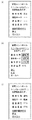
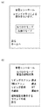
図2(a)は、操作前の機器24の状態を示す画面の一例であり、携帯端末12に表示される。図2(b)は、機器24の操作画面である。図2(c)は、操作内容を指示した後の機器24の状態を示す図である。ユーザは、機器24の動作状態を携帯端末12を使って確認できるので、機器24の遠隔制御を安心して行うことができる。この操作画面は、操作対象となる機器の種類に応じてカスタマイズされることが好ましい。
【0023】
図3は、ホームネットワーク50の構成図である。部屋52aには、信号変換装置100a、および機器24aが設置されている。部屋52bには、通信規格を満たしホームネットワーク50に直接接続可能な機器26aが設置されている。部屋52cには、信号変換装置100b、および機器24bが設置されている。信号変換装置100aおよび100bは、同一の機能ならびに構成を有する。部屋52dには、機器26bが設置されている。機器26aおよび26bは、同一の機能を有する。機器26a、26b、信号変換装置100a、100bは、商品コード、シリアルコード、MACアドレス等の装置固有の物理アドレス、ホームネットワーク50における論理アドレスなどの識別情報(以下、第1識別情報と表現する)によって区別されている。
【0024】
しかし、ユーザがそれらの第1識別情報を記憶し、個々に操作内容を指示することは困難である。信号中継装置200は、各々の機器に、ユーザが任意に識別情報(以下、第2識別情報と表現する)を設定し、その第2識別情報を使って操作対象機器を操作できるようにする。その第2識別情報は、ユーザが覚え易い名称であってよい。動作制御装置300は、ホームネットワーク50の複数の機器を、ひとつの命令で制御できるようにする。例えば、「外出モード」という命令に対応付けて、「リビング照明の消灯」、「リビングエアコンの停止」、「防犯システムの始動」といった命令を対応付けておき、ユーザが「外出モード」を指定したときに、動作制御装置300はそれらの命令を自動的に実行する。これにより、複数の機器をひとつの命令で制御できるので、ユーザは煩わしい操作から開放される。図1を用いた説明では、ホームゲートウェイ20がアプリケーション・サービス・プロバイダ18からの操作内容を規格信号に変換するとしたが、以下の説明では、信号中継装置200がその変換を行うこととする。
【0025】
図4は、信号変換装置100の内部構成図である。信号変換装置100の各構成要素は、ハードウエアコンポーネントで言えば、任意のコンピュータのCPU、メモリ、メモリにロードされたプログラム、ネットワーク接続用インターフェイスなどを中心に実現されるが、その実現方法、装置にはいろいろな変形例があることは、当業者には理解されるところである。これから説明する各図は、ハードウエア単位の構成ではなく、機能単位のブロックを示している。
【0026】
第1入出力部102は、ネットワーク22から規格信号を受信する受信部104と、状態信号をホームゲートウェイ20に送信する送信部106とを有する。変換部108は、規格信号を赤外線信号に変換する。また、変換部108は、赤外線信号に含まれる動作命令に基づいて、その動作が行われているか否かを推定するために利用する環境要素を動作状態提供部120に出力する。「環境要素」は、例えば温度、湿度等であり、機器24が空調機器の場合、変換部108は、温度の変化と、機器24の運転ランプの点灯状態とを検出することを動作状態提供部120に指示する。
【0027】
制御コード格納部110は、規格信号を機器24の独自の信号に変換するためのテーブルを保持する。規格信号には、動作内容を示す情報が含まれる。変換テーブルは、その動作内容に、機器24の独自の制御コマンドを対応付けたものである。変換部108は、制御コード格納部110に保持されている変換テーブルを使って、規格信号を赤外線信号に変換する。第2入出力部112は、その信号を赤外線を使って機器24に送信する発光部114を有する。発光部114は、赤外線を利用した双方向通信機能を有する機器28に対して赤外線信号を送信してもよい。第2入出力部112は、機器28から状態信号を受信する受光部116を更に有する。
【0028】
センサ118a、118bは、信号変換装置100の周辺の状態を検出する装置であり、例えば、温度センサ、湿度センサ、CCDカメラ、マイク等である。動作状態提供部120は、センサ118から供給されるセンサ情報に基づいて、機器24の動作状態を推定し、状態信号を送信部106に出力する。また、動作状態提供部120は、機器28が出力した状態信号を入力し、その状態信号とセンサ情報とに基づいて機器28の状態を推定してもよい。
【0029】
図5は、動作状態提供部120の内部構成図である。推定部126は、変換部108から指示された環境要素の検出が可能なセンサ118からセンサ情報を取得し機器24の動作状態を推定する。センサ制御部128は、動作状態の検出に利用するセンサ118の調整を行い、推定部126が推定に必要なセンサ情報を取得できるようにする。例えば、機器24の動作ランプの点灯状態に基づいて、動作を推定する場合、センサ制御部128は、動作ランプ付近を撮影するようにCCDカメラを制御する。
【0030】
判断部124は、推定部126が推定した状態信号と、第2入出力部112を介して供給される機器自らが出力した状態信号とを入力して、いずれか一方を第1入出力部102に出力する。操作対象となる機器が機器28のように双方向通信機能を備え、自ら状態信号を出力できる場合に、判断部124はいずれか一方の状態信号を出力する。優先信号設定部122は、いずれの状態信号を出力するかを判断部124に指定する。例えば、優先信号設定部122に「優先」が設定されているとき、判断部124は、推定部126からの状態信号を第1入出力部102に出力する。優先信号設定部122に「自動」が設定されているとき、判断部124は、機器28からの状態信号を第1入出力部102に出力する。判断部124は、一定の間隔で状態信号を第1入出力部102に出力してもよいし、例えば、室温が設定温度に到達したとき等、一定の条件を満たしたときに出力してもよい。このような信号変換装置100により、通信規格を満たしていない機器も、ホームネットワーク50に間接的に接続できる。
【0031】
図6は、信号中継装置200の内部構成図である。信号中継装置200は、ホームネットワーク50に接続された機器をユーザが任意に付けた名称で管理できるようにする。登録部216は、機器固有の識別情報である第1識別情報と、ユーザが任意にその機器に付けた識別情報である第2識別情報とを対応付けて識別情報格納部214に登録する。取得部220は、ホームネットワーク50に接続された機器の第1識別情報を取得する。
【0032】
間取情報格納部218は、ホームネットワーク50が構築されているユーザ宅の間取りの情報を保持する。例えば、間取りの情報は、「リビング」、「キッチン」、「寝室」、「子供部屋」等の部屋名と、その広さ、位置などの情報を保持する。
【0033】
図7は、登録部216により生成された第2識別情報の登録画面の一例を示す図である。この登録画面は、ホームネットワーク50に接続されているテレビジョンやコンピュータのモニタ等に表示される。機器情報表示領域250は、ホームネットワーク50に新たに追加された機器の情報が表示される。この情報は、取得部220により取得され、例えば、プラグ・アンド・プレイ機能を利用して取得されてよい。もちろん、ユーザが自ら入力してもよい。間取表示領域252は、ユーザ宅の間取りが表示される。登録部216は、間取情報格納部218に保持されている情報に基づいてこの間取りを表示する。機器を登録する場合、例えば、ユーザは、機器情報表示領域250に表示されている機器のアイコンを、実際の設置場所に対応する間取り上の位置にドラックする。これにより、第1識別情報と設置場所とが対応付けられる。
【0034】
第2識別情報入力領域254は、その機器の第2識別情報を入力する領域である。第2識別情報を入力し、登録ボタン256を押すことで、第1識別情報と第2識別情報とが対応付けられる。このような入力インターフェイスをユーザに提供することで、ユーザは直感的に、かつ容易に機器の登録が可能になる。
【0035】
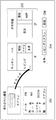
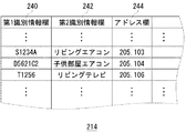
図8は、図6の識別情報格納部214のデータ構造の一例を示す図である。第1識別情報欄240は第1識別情報を保持する。第2識別情報欄242は、第2識別情報を保持する。ネットワークアドレス欄244は、ホームネットワーク50におけるアドレスを保持する。本図で、第1識別情報が「S1234A」の機器は、ユーザにより第2識別情報として「リビングエアコン」が設定されている。また、そのアドレスは、「205.103」であることがわかる。
【0036】
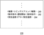
図6に戻り、第1制御信号受信部202は、ネットワーク22から第1制御信号230を受信する。第1制御信号230は、アプリケーション・サービス・プロバイダ18からの操作内容を示す信号である。図9は、第1制御信号230に含まれるデータの一例を示す図である。第1制御信号230は、例えば、XML(eXtensible Markup Language)形式で構成されている。機器指定欄260は、操作対象となる機器を特定する第2識別情報を保持する。動作指示欄262は、操作内容を保持する。設定温度欄264は、設定温度を保持する。本図は、エアコンを制御するための命令を一例に第1制御信号230を示しているので、設定温度欄264があるが、機器の種類によっては、第1制御信号230に含まれていなくてもよい。
【0037】
第1制御信号230は、少なくとも機器指定欄260と動作指示欄262とが含まれていればよく、それ以外のデータは操作対象となる機器に応じて任意に決めることができる。図6に戻り、選択部206は、第1制御信号230の機器指定欄260に保持されている第2識別情報に対応付けられている第1識別情報を、識別情報格納部214から取得する。そして、選択部206は取得した第1識別情報と、第1制御信号230とを生成部208に出力する。
【0038】
生成部208は、規格信号である第2制御信号232を生成して、第2制御信号送信部210に出力する。図10は、第2制御信号232のデータ構造の一例を示す図である。EHDは、第2制御信号232のヘッダ情報を保持する。SEAは、ホームネットワーク50における送信元アドレスを保持する。例えば、SEAは、信号中継装置200のアドレスを保持する。DEAは、送信先アドレスを保持する。図9で示した第1制御信号230を変換した場合、第2識別情報「リビングエアコン」に対応付けられたアドレスは、図7より「205.103」であることがわかるので、DEAには、「205.103」が保持される。EBCは、EDATAのバイト数を保持する。
【0039】
EDATAは、通信規格における機器の操作内容を指示する情報を保持する。EDATAは、OHD、SEOJ、DEOJ、EPC、ESV、EDTを有する。OHDは、オブジェクト電文ヘッダーである。SEOJ、DEOJは、それぞれ送信元と送信先の機器の種類を特定する情報である。EPCは、設置場所や動作内容を示すプロパティである。ESVは、EPCに保持されるプロパティに対する操作を指定する。EDTは、プロパティ値を保持する。図8で示した第1制御信号230を変換した場合、DEOJにはエアコンを示す情報が保持され、EDTには、運転を開始するための情報と、設定温度を指定するための情報とが保持される。このデータ構造は例示であり、他の実施の形態においては別のデータ構造であってもよい。
【0040】
図6に戻り、第2制御信号送信部210は、第2制御信号232を操作対象となる機器に送信する。第2状態信号受信部212は、機器から規格信号に基づいた状態信号(以下、第2状態信号と表現する)を受信する。生成部208は、その第2状態信号をアプリケーション・サービス・プロバイダ18が認識できる形式の信号(以下、第1状態信号と表現する)に変換し、選択部206に出力する。選択部206は、第2状態信号を送信した機器のアドレスに対応付けられた第2識別情報を取得して、そのアドレスと置き換えて、第1状態信号送信部204に出力する。第1状態信号送信部204は、第1状態信号をホームゲートウェイ20に送信する。ホームゲートウェイ20は、その第1状態信号を図1のアプリケーション・サービス・プロバイダ18に送信する。アプリケーション・サービス・プロバイダ18は、第1状態信号に基づいて、機器の状態をユーザに提示する画面データを生成し、携帯端末12の表示部に表示させる。このような信号中継装置200により、ユーザはホームネットワーク50に接続された機器を、任意の名称で管理できる。
【0041】
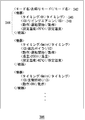
図3の動作制御装置300により、ユーザは、ひとつの命令で、ホームネットワーク50に接続された複数の機器を制御することができる。図11(a)は、この機能を利用する際の、図1の携帯端末12に表示された操作画面の一例を示す図である。本図の操作画面では、「おでかけモード」と「お帰りモード」が表示されており、ユーザは、いずれか一方を選択する。図11(b)は、ユーザが「おでかけモード」を選択した場合に、携帯端末12に表示される運転状態を示す画面の一例を示す図である。例えば、ユーザが「おでかけモード」を指示すると、「リビングエアコン」、「2階エアコン」の運転が停止され、「リビング照明」が消される。
【0042】
図12は、図3の動作制御装置300の内部構成図である。登録部302は、連動して操作を行う機器と、その操作内容とをユーザから受け付ける。登録部302は、その情報を連動情報ファイル生成部304に出力する。連動情報ファイル生成部304は、連動して動作させる機器とその操作内容とを示すファイル(以下、連動情報ファイルと表現する)を生成する。電力推定部314は、連動情報ファイルに示された機器が同時に動作するために必要な電力を算出する。そして、連動情報ファイル生成部304は、電力推定部314により算出された電力が、ユーザ宅の最大消費電力を超えていない場合に、その連動情報ファイルを連動情報ファイル格納部306に格納する。これにより、ユーザ宅のブレーカが落ちることを防止できる。
【0043】
また、連動情報ファイル生成部304は、複数の機器を連動して動作させる場合に、その機器の運転開始タイミングを変えるように連動情報ファイルを生成してもよい。一般に、電気機器は、運転を始めるときに大量の電流が流れ、しばらくすると消費電流は小さくなる。したがって、運転を開始するタイミングをずらすことで、機器の動作開始時にブレーカが落ちることを防止できる。
【0044】
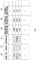
図13は、機器情報格納部318のデータ構造の一例を示す図である。機器ID欄360は、機器の第1識別情報を保持する。種別欄362は、機器の種別を保持する。設置場所欄364は、機器の設置場所を保持する。運転開始時消費電力欄366は、運転開始時の消費電力を保持する。定常運転時消費電力欄368は、定常運転時の消費電力を保持する。定常運転遷移時間欄370は、機器が運転を開始してから、定常運転になるまでの時間を保持する。
【0045】
例えば、第1識別情報「S1234A」で特定される機器の種別は「エアコン」であり、その設置場所は「リビング」であることがわかる。そして、その機器の運転開始時の消費電力は「1000W」であり、運転開始から「5分後」には定常運転になり、そのときの消費電力は「800W」であることがわかる。
【0046】
図12に戻り、基本連動情報生成部312は、基本ファイル格納部316に保持されている基本ファイルと、機器情報格納部318に保持されるデータとに基づいて、連動情報ファイルを自動的に生成する。図14は、基本ファイル格納部316に保持されている「お帰りモード」用の基本ファイルの一例を示す図である。モード名称欄342は、モード名称を保持する。機器情報欄340は、連動して動作させる機器毎に設けられる。例えば、3種類の機器を連動して動作させる場合には、3つの機器情報欄340が基本ファイルには設けられる。それぞれの機器に対する制御信号は、例えば、機器情報欄340の順番に合わせて送信される。
【0047】
それぞれの機器情報欄340には、機器の種別、動作内容が少なくとも含まれる。また、機器の種類に応じて、設置場所、設定温度、湯量、チャンネル等の情報が含まれる。本図の場合、まず、「リビング」に設置されている「エアコン」の運転を開始し、次に「風呂のボイラ」を運転し、その後「玄関」の「照明」を点灯することが基本ファイルとして設定されている。
【0048】
図15は、連動情報ファイルの一例を示す図である。モード名称欄342は、モード名称を保持する。機器情報欄344は、連動して操作する機器毎に設けられる。それぞれの機器情報欄344は、図14で説明した基本ファイルに含まれる項目に加えて、少なくとも、操作対象機器を特定する情報を保持する機器ID欄348が含まれる。タイミング欄346は、動作タイミングを指定する情報を保持し、一番最初の制御信号が出された時点を開始時間として、開始時間からの時間を動作タイミングとして保持してもよいし、直前の制御信号が出されたタイミングからの時間を動作タイミングとして保持してもよい。
【0049】
連動情報ファイル生成部304は、図13で説明した機器情報格納部318に保持される定常運転までの遷移時間に基づいて動作タイミングを決めてタイミング欄346に保持させる。連動情報ファイル生成部304は、例えば、消費電力が大きい順に動作タイミングを設定してもよい。連動情報ファイル生成部304は、図13の機器ID欄360に保持されている第1識別情報に、対応付けられた第2識別情報を図6の識別情報格納部214から取得して、機器ID欄348に保持させる。
【0050】
図15で示す連動情報ファイルの場合、まず「リビングエアコン」に対して運転開始指示が出され、その指示の5分後に「風呂ボイラ」に対して運転開始指示が出される。そして、「リビングエアコン」の運転開始指示から6分後に「玄関照明」を点灯する指示が出される。このようにして生成した連動情報ファイルは連動情報ファイル格納部306に格納される。
【0051】
図12に戻り、指示部308は、ユーザに指定されたモード名称の連動情報ファイルを連動情報ファイル格納部306から読み込み、指定されたタイミングで制御信号を信号中継装置200に送信する。本実施の形態では、信号中継装置200が制御信号を規格信号に変換する。電力検出部310は、実際の消費電力を検出する。電力検出部310は、自らが電流を測定し電力を算出してもよいし、ネットワークに接続された電力値を提供する装置から、電力値の情報だけを取得してもよい。指示部308は、実際の消費電力と次に制御信号を送信する送信先機器の消費電力から、その機器を動作可能か否かを判定して、動作可能であると判定した場合に、その制御信号を送信する。これにより、ユーザ宅のブレーカが落ちることを防止できる。
【0052】
図16は、動作制御装置300における連動情報ファイルの作成および登録処理のフローチャートである。まず、登録部302は、基本ファイルに基づいて連動情報ファイルを自動生成するか、ユーザが自ら連動情報ファイルを生成するかを問い合わせる(S10)。自動生成する場合(S10のY)、基本連動情報生成部312は、基本ファイル格納部316から基本ファイルを選択し(S12)、その基本ファイルに基づいて、該当する機器を機器情報格納部318から抽出する(S14)。
【0053】
そして、基本連動情報生成部312は、連動情報ファイルを連動情報ファイル生成部304に出力する。登録部302は、その連動情報ファイルをユーザに提示し、ユーザからその連動情報ファイルの変更を受け付ける(S16)。連動情報ファイル生成部304は、機器の動作タイミングなどを調整して連動情報ファイルを完成する(S18)。電力推定部314は、その連動情報ファイルに基づいて、消費電力を推定して、設定された全ての機器を操作可能か否かを判定する(S20)。操作可能の場合(S20のY)、連動情報ファイル生成部304は、連動情報ファイルを連動情報ファイル格納部306に登録する(S22)。S20で、すべての機器を操作できない場合(S20のN)、電力推定部314は、その旨をユーザに通知し、変更を促す(S24)。S10で、ユーザが自ら連動情報ファイルを作成する場合(S10のN)、登録部302は、ユーザから連動して操作する機器を受け付け(S26)、連動情報ファイル生成部304は受け付けた機器の連動情報ファイルを生成する(S18)。
【0054】
図17は、指示部308における制御信号送信処理のフローチャートである。指示部308は、連動情報ファイル格納部306から連動情報ファイルを読み込む(S30)。そして、未だ制御信号を送信するための処理を行っていない機器情報340が連動情報ファイルにあるか否かを判定する(S32)。未処理の機器情報340がある場合(S32のY)、指示部308は制御信号を生成する(S34)。そして、制御信号の送信タイミングになるまで待機する(S36のN)。送信タイミングになったとき(S36のY)、指示部308は、電力検出部310から現在の消費電力を取得し(S38)、操作対象となる機器の操作により、消費電力が規定値を超えるか否かを判定する(S40)。超えない場合(S40のY)、制御信号を信号中継装置200に送信する(S42)。
【0055】
S40で、消費電力が規定値を超える場合(S40のN)、その旨をユーザに通知し(S44)、S32に戻る。これにより、ある機器を運転することはできなくとも、他の消費電力が少ない機器の運転をすることができる。
【0056】
<第2の実施形態>
図18は、第2の実施形態における家電制御システム70の構成図である。本図で、既に説明した構成と同一の符号を付した構成は、既に説明した構成と同一もしくはほぼ同一の機能を有する。これから説明する各図では、既に説明した構成と異なる構成について主に説明する。家電制御システム70は、信号変換装置400から赤外線信号を受信して、その信号に応じた信号(以下、単に「第1応答信号」という)を送信する応答装置410と、機器24に流入する電流もしくは、機器24で消費される電力を計測して、計測値に基づいて生成した信号(以下、単に「第2応答信号」という)を送信する電流測定装置450を備える。本実施形態では、電流測定装置450が機器24に流入する電流に基づいて第2応答信号を生成する場合を一例に説明する。詳細は後述するが、家電制御システム70は、応答装置410および電流測定装置450を備えることにより、規格信号を送信した後、即座に機器24の動作状態をユーザに通知することができる。
【0057】
応答装置410は、着脱可能な装置であり、機器24の赤外線通信部60で受信される赤外線信号を受信できるように、赤外線通信部60の周辺、すなわち信号変換装置400が送信する赤外線信号の照射範囲内に取り付けられる。機器24は、電流測定装置450を介してコンセント62に接続される。他の例では、応答装置410および電流測定装置450のいずれか一方が機器24に取り付けられてもよい。
【0058】
図19は、図18の信号変換装置400の内部構成図である。発光部114は、規格信号を例えば赤外線を利用して機器24に送信する。応答装置410は、その赤外線信号を受信して、第1応答信号を受光部116に向けて送信する。電流測定装置450は、機器24に流入する電流を測定して、第2応答信号を受光部116に向けて送信する。動作状態提供部120は、応答装置410および電流測定装置450もセンサ118のひとつとして扱い、第1応答信号および第2応答信号も他のセンサ情報とともに機器24の動作状態の推定に利用する。このように、センサ118は、信号変換装置400に取り付けられていてもよいし、応答装置410および電流測定装置450のように外部に配置されていてもよい。
【0059】
図20は、図19の動作状態提供部120の内部構成図である。分離部402は、図19の受光部116が受光した信号を、機器28から送信された状態信号と、応答装置410または電流測定装置450から送信された第1応答信号もしくは第2応答信号とを分離する。分離部402は、状態信号を判断部124に供給し、第1応答信号および第2応答信号を推定部126に供給する。推定部126は、例えば第1応答信号が赤外線信号を受信したことを示す信号であるか否かを判定し、受信したことを示す信号の場合、指示通りに機器24が動作していると推定する。また推定部126は、受信したことを示さない信号を受信した場合、または赤外線信号を送信してから所定の時間が経過しても第1応答信号が到達しない場合、指示通りに機器24が動作していないと推定する。
【0060】
また、第2応答信号に基づいて機器24の動作状態を推定する場合、推定部126は、機器24に流入する電流量の変化に基づいて推定を行ってもよい。例えば、電流量が増大した場合に、推定部126は機器24の電源が入り、所定の動作を開始したと推定する。逆に、電流量が減少した場合に、推定部126は機器24の電源が切られ、所定の動作が終了したと推定する。また、推定部126は、第1応答信号および第2応答信号ならびに各種のセンサ情報を組み合わせて、機器24の動作状態の推定を行ってもよい。これにより、赤外線信号の送信を契機に、短時間で動作状態の推定が可能になり、また推定精度も向上する。
【0061】
図21は、図18の応答装置410の内部構成図である。受光部412は、信号変換装置400から赤外線信号を受光する。制御信号検出部414は、受光した赤外線信号から制御信号を検出する。制御信号検出部414が検出すべき制御信号は、例えば応答装置410を装着する機器24に応じて予め登録されていてもよい。また制御信号検出部414は、予め複数の種類の機器24に対応した制御信号を保持し、応答装置410を機器24に装着する際に、例えばディップスイッチなどを利用して機器24の種類の指定を受け付けることで、その種類に対応づけられた制御信号が検出すべき制御信号として設定されてもよい。
【0062】
応答信号生成部416は、制御信号検出部414が検出した制御信号に基づいて第1応答信号を生成し、発光部418に供給する。そして、発光部418は、赤外線を使って第1応答信号を信号変換装置400に送信する。応答信号生成部416は、例えば検出した制御信号をそのまま第1応答信号として生成してもよいし、検出した制御信号に応答装置410を識別するためのコード(以下、単に「装置ID」という)を付加して第1応答信号を生成してもよい。また、応答信号生成部416は、検出した制御信号に対応する別のコードに装置IDを付加して第1応答信号を生成してもよい。このように、装置IDを付加することで、同時に複数の応答装置410が第1応答信号を送信した場合に、例えば赤外線の干渉により正常な応答ができなくなることを防止できる。電源部420は、例えば電池や太陽電池などにより応答装置410における各機能ブロックに電力を供給するユニットである。
【0063】
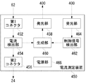
図22は、図18の電流測定装置450の内部構成図である。第1コネクタ452は、例えば雄型のプラグであって機器24に供給する電源であるコンセント62と接続し、第2コネクタ456は、例えば雌型のプラグであって機器24の電源ケーブルと接続する。第1コネクタ452および第2コネクタ456は、電流検出部454を介して接続されている。電流検出部454は、第1コネクタ452および第2コネクタ456を流れる電流量を測定し、測定値を生成部460に供給する。電流検出部454は、所定の時間間隔で電流量の測定を行い、生成部460に供給してもよいし、生成部460から指示された場合に測定を行い、測定結果を生成部460に供給してもよい。
【0064】
受光部464は、信号変換装置400から機器24を制御するための赤外線信号を受信して、制御信号検出部462に供給する。制御信号検出部462は、予め設定された制御信号を検出し、検出したことを生成部460に通知する。制御信号検出部462に予め設定される制御信号は、例えば機器24の運転の開始や停止を指示するための制御信号であってよい。生成部460は、その通知を契機として電流検出部454から供給された測定値に基づいて第2応答信号を生成し、発光部458に供給する。発光部458は、赤外線を使って第2応答信号を信号変換装置400に送信する。生成部460は、制御信号を受信した前後の電流値を監視して、電流値に所定の値以上の変化が生じた場合に機器24の運転の開始、もしくは停止を示す第2応答信号を生成してもよい。他の形態では、生成部460は、定期的に測定値を示す第2応答信号を生成し、信号変換装置400に送信し、図20の推定部126が第2応答信号に基づいて、電流値の変化を監視して、機器24の運転の開始もしくは停止を推定してもよい。電源部466は、例えば第2コネクタ456から電気を取得して電流測定装置450における各機能ブロックに電力を供給するユニットである。また、電源部466は、例えば電池、太陽電池などにより電流測定装置450における各機能ブロックに電力を供給してもよい。
【0065】
以上、本発明を実施の形態をもとに説明した。この実施の形態は例示であり、それらの各構成要素や各処理プロセスの組合せにいろいろな変形例が可能なこと、またそうした変形例も本発明の範囲にあることは当業者に理解されるところである。以下そうした変形例をいくつか挙げる。
【0066】
第1の変形例は、信号変換装置100における第2入出力部112に関する。赤外線を使って信号を伝送する場合、発光部から受光部までの間に障害物があると信号の伝達ができない。そこで、第2入出力部112は、単方向信号を電波を利用して送信する構成と、その電波を受信して赤外線を発光する信号変換装置100とは別体の発光ユニットを更に備えてもよい。これにより、信号変換装置100を任意の場所に設置し、発光ユニットを機器24の受光部付近に設置できる。更に、発光ユニットに識別情報を付与すれば、その識別情報宛に単方向信号を送信できる。これにより、ひとつの信号変換装置100で複数の機器24に対して赤外線信号を送信できる。
【0067】
第2の変形例は、信号変換装置100における制御コード格納部110に関する。制御コード格納部110に保持されている変換テーブルは、予め保持されていてもよいし、赤外線信号を学習するユニットを更に備え、そのユニットによる学習の度に新たに保持されてもよい。
【0068】
第3の変形例は、信号変換装置100に関する。信号変換装置100は、複数のセンサ118を有するが、例えばCCDカメラなどを防犯用の監視カメラとして利用してもよい。
【0069】
第4の変形例は、信号中継装置200および動作制御装置300の信号伝達に関する。実施の形態では、動作制御装置300は制御信号を信号中継装置200に送信し、信号中継装置200がその制御信号を受信して規格信号を生成して各々の機器に送信するとした。変形例では、動作制御装置300が規格信号を生成してそれぞれの機器に送信してもよい。
【0070】
第5の変形例は、動作制御装置300に関する。動作制御装置300は、ネットワークに接続された各々の機器の動作状態を検出する検出部と、その検出部に検出処理を開始する指示をユーザから受け付ける受付部とを更に備えてもよい。検出部は、ユーザから指示を受けた場合に、動作状態の検出を行い、検出を行った機器の識別情報と、動作状態とを登録部302に出力する。連動情報ファイル生成部304は、それらの情報に基づいて、ユーザが任意に指定したモードに対応付けて連動情報ファイルを生成する。これにより、ユーザが体験中の環境、例えば、エアコンの調整や、室内の明るさ、ステレオの音量などを、いちいち機器ごとに操作内容を設定することなく、各機器の操作内容を任意の動作モードに対応付けて保持させることができる。
【0071】
第6の変形例は、図22の電流測定装置450に関する。生成部460は、電流検出部454から供給される一連の測定値に基づいて電流波形を特定し、その波形パターンに基づいて機器24の動作状態を示す第2応答信号を生成してもよい。
【0072】
第7の変形例は、図1の信号変換装置100および図18の信号変換装置400に関する。信号変換装置100および信号変換装置400を、それぞれ例えば自走式のロボットなどに搭載してもよい。これにより、信号変換装置100または信号変換装置400を各部屋に設けなくてもよい。
【0073】
【発明の効果】
本発明によれば、ネットワーク接続機能を有しない機器をホームネットワークに取り込むことができる。
【図面の簡単な説明】
【図1】実施の形態に係る家電制御システムの構成図である。
【図2】図1の携帯端末の表示画面の一例を示す図である。
【図3】図1のホームネットワークの構成図である。
【図4】図1の信号変換装置の内部構成図である。
【図5】図4の動作状態提供部の内部構成図である。
【図6】図3の信号中継装置の内部構成図である。
【図7】図6の登録部により作成される登録画面の一例を示す図である。
【図8】図6の識別情報格納部のデータ構造の一例を示す図である。
【図9】図6の第1制御信号受信部が受信する第1制御信号のデータ構造の一例を示す図である。
【図10】図6の生成部が生成する第2制御信号のデータ構造の一例を示す図である。
【図11】図1の携帯端末の表示画面の一例を示す図である。
【図12】図3の動作制御装置の内部構成図である。
【図13】図12の機器情報格納部のデータ構造の一例を示す図である。
【図14】図12の基本ファイル格納部に保持される基本ファイルのデータ構造の一例を示す図である。
【図15】図12の連動情報ファイル格納部に保持される連動情報ファイルのデータ構造の一例を示す図である。
【図16】動作制御装置における連動情報ファイルの登録処理のフローチャートである。
【図17】図12の指示部における制御信号を出力する際のフローチャートである。
【図18】第2の実施形態における家電制御システムの構成図である。
【図19】図18の信号変換装置の内部構成図である。
【図20】図19の動作状態提供部の内部構成図である。
【図21】図18の応答装置の内部構成図である。
【図22】図18の電流測定装置の内部構成図である。
【符号の説明】
10 家電制御システム、16 ネットワーク、18 アプリケーション・サービス・プロバイダ、20 ホームゲートウェイ、22 ネットワーク、60 赤外線通信部、62 コンセント、100 信号変換装置、102 第1入出力部、108 変換部、110 制御コード格納部、112 第2入出力部、118 センサ、120 動作状態提供部、122 優先信号設定部、124 判断部、126 推定部、128 センサ制御部、202 第1制御信号受信部、206 選択部、208 生成部、210 第2制御信号送信部、214 識別情報格納部、216 登録部、304 連動情報ファイル生成部、306 連動情報ファイル格納部、308 指示部、310 電力検出部、312 基本連動情報生成部、314 電力推定部、316 基本ファイル格納部、400 信号変換装置、402 分離部、410 応答装置、412 受光部、414 制御信号検出部、416 応答信号生成部、418 発光部、450 電流測定装置、452 第1コネクタ、454 電流検出部、456 第2コネクタ、458 発光部、460 生成部、462 制御信号検出部、464 受光部。[0001]
TECHNICAL FIELD OF THE INVENTION
The present invention relates to a signal conversion technique, and more particularly to a device for converting a signal between devices in a network using a wired or wireless network.
[0002]
[Prior art]
As seen on the Internet, computer networking is steadily progressing. As the network environment including infrastructure such as ADSL and optical fiber is prepared, the Internet is beginning to penetrate as a part of people's lives. Under these circumstances, home appliances are being incorporated into networks to build home networks aimed at energy saving and home health care.
[0003]
Communication technology using wired or wireless is indispensable for such home networks. For example, there are organizations that standardize network technology between home appliances, and are promoting standardization of a two-way communication method between devices connected to a home network, a control method, and the like.
[0004]
This standard defines, for example, the format of a connection with a device to be controlled, the format of an operation command, the format of notification information from the device, and the like. According to a device based on this standard, for example, a user can remotely control a device at home using a terminal such as a telephone from outside.
[0005]
[Problems to be solved by the invention]
In order to construct a home network, for example, a device that meets the standard is required. For this reason, the user needs to purchase a new device corresponding to the home network.
[0006]
The present inventor has made the present invention by focusing on such a current situation, and an object of the present invention is to provide a technique for incorporating a device having no network connection function into a home network. Another object is to provide a device that realizes such a function. Still another object is to provide a technology for smoothly moving to a home network.
[0007]
[Means for Solving the Problems]
One embodiment of the present invention relates to a signal conversion device. The apparatus includes: a receiving unit that receives a first control signal for controlling a first device having a two-way communication function using a network via the network; A conversion unit that converts the signal into a second control signal for controlling a second device that cannot recognize the signal, and using the one-way communication function different from the two-way communication function to send the second control signal to the second device. A transmission unit for transmitting. The “first device” is, for example, a device that satisfies the above-described standardization standard, and the “second device” is a conventional device that does not satisfy the standardization standard. The “one-way communication function” is a communication function using infrared rays, for example, used as an “infrared remote control”. The “network” includes a wired LAN such as a telephone line, a power line, and Ethernet (registered trademark), and a wireless LAN such as PHS (registered trademark), Bluetooth (registered trademark), and IEEE802.11 standard.
[0008]
Another embodiment of the present invention also relates to a signal conversion device. The device includes a receiving unit that receives a first control signal for controlling a first device having a two-way communication function, and a receiving unit that receives the first control signal for controlling a second device having a one-way communication function. A conversion unit that converts the second control signal into a second control signal; a transmission unit that transmits the second control signal to the second device; and an operation state of the second device based on an environmental state around the second device. And an estimating unit. The “environmental state” is, for example, a state such as temperature, humidity, volume, and brightness.
[0009]
The device further includes a plurality of types of sensors for detecting an environmental condition around the second device, wherein the conversion unit changes according to an operation to be performed by the second device that has received the second control signal. A sensor for detecting the state of the environmental element may be instructed to the estimating unit, and the estimating unit may estimate the operation state based on the environmental state detected by the instructed sensor. “Sensor” is used in a broad sense, and is, for example, a temperature sensor, a humidity sensor, a CCD camera, a microphone, or the like. “Environmental elements” refer to individual factors that determine the environment, such as temperature, humidity, and volume, and a sensor for detecting a state is determined for each environmental element.
[0010]
Yet another embodiment of the present invention also relates to a signal conversion device. This device includes a receiving unit that receives a first state signal indicating an operation state of the device from a predetermined device having a two-way communication function, and a signal from a sensor that detects an environmental state around the predetermined device. An estimating unit for estimating an operation state of the predetermined device and outputting a second state signal, and outputting one of the first state signal and the second state signal to a device requiring the signal; And a state providing unit. The “operating state” is, for example, an operating state of the device such as “during operation” or “during stop”.
[0011]
The state providing unit is different from the determining unit that determines whether the first state signal and the second state signal indicate the same operation state, and the first state signal and the second state signal are different. A priority signal setting unit that sets one of the status signals to be output with priority when indicating an operation state may be provided.
[0012]
Yet another embodiment of the present invention also relates to a signal conversion device. The device includes a first receiving unit that receives a first control signal for controlling a first device having a two-way communication function, and controls the first control signal to control a second device having a one-way communication function. A conversion unit for converting the second control signal into a second control signal, a transmission unit for transmitting the second control signal to the second device, and a third device detachably attached to the second device. A second receiving unit that receives a signal indicating that the signal has been received. The first receiving unit and the second receiving unit may be the same receiving unit.
[0013]
Yet another embodiment of the present invention also relates to a signal conversion device. The device includes a first receiving unit that receives a first control signal for controlling a first device having a two-way communication function, and controls the first control signal to control a second device having a one-way communication function. A converting unit for converting the second control signal into a second control signal, a transmitting unit for transmitting the second control signal to the second device, and a third device detachably attached to the second device. And a second receiving unit that receives a signal generated based on the amount of current flowing into the device.
[0014]
Yet another embodiment of the present invention also relates to a signal conversion device. This device includes a receiving unit that receives a first state signal indicating an operation state of the device from a predetermined device having a two-way communication function, and a signal from a sensor that detects an amount of current flowing into the predetermined device. An estimating unit for estimating an operation state of the predetermined device and outputting a second state signal, and outputting one of the first state signal and the second state signal to a device requiring the signal; And a state providing unit.
[0015]
Yet another embodiment of the present invention also relates to a signal conversion device. The apparatus includes a receiving unit that receives a first state signal indicating an operation state of the apparatus from a predetermined apparatus having a bidirectional communication function, and a first sensor that detects an environmental state around the predetermined apparatus. An estimating unit that estimates an operation state of the predetermined device based on a signal and a signal from a second sensor that detects an amount of current flowing into the predetermined device, and outputs a second state signal; A state providing unit that outputs one of the state signal and the second state signal to a device that requires the signal. Further, the second sensor may be detachably attached to the predetermined device.
[0016]
It is to be noted that any combination of the above-described components and any conversion of the expression of the present invention between a method, an apparatus, a system, a recording medium, a computer program, and the like are also effective as embodiments of the present invention.
[0017]
BEST MODE FOR CARRYING OUT THE INVENTION
<First embodiment>
FIG. 1 is a configuration diagram of a home
[0018]
The
[0019]
The user uses the
[0020]
Alternatively, the
[0021]
The
[0022]
FIG. 2A is an example of a screen showing the state of the
[0023]
FIG. 3 is a configuration diagram of the
[0024]
However, it is difficult for the user to store the first identification information and individually instruct operation contents. The
[0025]
FIG. 4 is an internal configuration diagram of the
[0026]
The first input /
[0027]
The control
[0028]
The
[0029]
FIG. 5 is an internal configuration diagram of the operation
[0030]
The determining
[0031]
FIG. 6 is an internal configuration diagram of the
[0032]
The floor plan
[0033]
FIG. 7 is a diagram illustrating an example of a registration screen of the second identification information generated by the
[0034]
The second identification
[0035]
FIG. 8 is a diagram illustrating an example of a data structure of the identification
[0036]
Returning to FIG. 6, the first control
[0037]
The
[0038]
The
[0039]
The EDATA holds information for instructing the operation of the device in the communication standard. EDATA has OHD, SEOJ, DEOJ, EPC, ESV, and EDT. OHD is an object message header. SEOJ and DEOJ are information for specifying the types of the source and destination devices, respectively. EPC is a property indicating an installation location and operation contents. The ESV specifies an operation for a property held in the EPC. EDT holds property values. When the
[0040]
Returning to FIG. 6, the second control
[0041]
With the
[0042]
FIG. 12 is an internal configuration diagram of the
[0043]
Further, when a plurality of devices are operated in a linked manner, the linked information
[0044]
FIG. 13 is a diagram illustrating an example of a data structure of the device
[0045]
For example, the type of the device specified by the first identification information “S1234A” is “air conditioner”, and the installation location is “living room”. Then, the power consumption at the start of the operation of the device is “1000 W”, the steady operation is performed “5 minutes after the start of the operation”, and the power consumption at that time is “800 W”.
[0046]
Returning to FIG. 12, the basic interlocking
[0047]
Each
[0048]
FIG. 15 is a diagram illustrating an example of the link information file. The mode name column 342 holds a mode name. The
[0049]
The interlocking information
[0050]
In the case of the linked information file shown in FIG. 15, an operation start instruction is first issued to “living air conditioner”, and an operation start instruction is issued to “bath boiler” five minutes after the instruction. Then, an instruction to turn on the “entrance light” is issued six minutes after the operation start instruction of the “living air conditioner”. The link information file generated in this way is stored in the link information
[0051]
Returning to FIG. 12, the
[0052]
FIG. 16 is a flowchart of the process of creating and registering the linked information file in the
[0053]
Then, the basic linkage
[0054]
FIG. 17 is a flowchart of the control signal transmission process in the
[0055]
In S40, when the power consumption exceeds the specified value (N in S40), the user is notified to that effect (S44), and the process returns to S32. Thus, even if it is impossible to operate a certain device, it is possible to operate another device with low power consumption.
[0056]
<Second embodiment>
FIG. 18 is a configuration diagram of a home
[0057]
The
[0058]
FIG. 19 is an internal configuration diagram of the
[0059]
FIG. 20 is an internal configuration diagram of the operation
[0060]
When estimating the operation state of the
[0061]
FIG. 21 is an internal configuration diagram of the
[0062]
The
[0063]
FIG. 22 is an internal configuration diagram of the
[0064]
The
[0065]
The present invention has been described based on the embodiments. This embodiment is an exemplification, and it is understood by those skilled in the art that various modifications can be made to the combination of each component and each processing process, and that such modifications are also within the scope of the present invention. is there. The following are some of such modified examples.
[0066]
The first modification example relates to the second input /
[0067]
The second modification relates to the control
[0068]
The third modification example relates to the
[0069]
The fourth modification relates to signal transmission of the
[0070]
The fifth modification example relates to the
[0071]
The sixth modification example relates to the
[0072]
The seventh modification example relates to the
[0073]
【The invention's effect】
According to the present invention, a device having no network connection function can be taken into a home network.
[Brief description of the drawings]
FIG. 1 is a configuration diagram of a home appliance control system according to an embodiment.
FIG. 2 is a diagram showing an example of a display screen of the mobile terminal of FIG.
FIG. 3 is a configuration diagram of the home network of FIG. 1;
FIG. 4 is an internal configuration diagram of the signal conversion device of FIG. 1;
FIG. 5 is an internal configuration diagram of an operation state providing unit of FIG. 4;
FIG. 6 is an internal configuration diagram of the signal relay device of FIG. 3;
FIG. 7 is a diagram illustrating an example of a registration screen created by a registration unit in FIG. 6;
FIG. 8 is a diagram illustrating an example of a data structure of an identification information storage unit in FIG. 6;
9 is a diagram illustrating an example of a data structure of a first control signal received by a first control signal receiving unit in FIG. 6;
FIG. 10 is a diagram illustrating an example of a data structure of a second control signal generated by a generation unit in FIG. 6;
FIG. 11 is a diagram showing an example of a display screen of the mobile terminal of FIG.
FIG. 12 is an internal configuration diagram of the operation control device of FIG. 3;
13 is a diagram illustrating an example of a data structure of a device information storage unit in FIG.
FIG. 14 is a diagram illustrating an example of a data structure of a basic file held in a basic file storage unit in FIG. 12;
FIG. 15 is a diagram illustrating an example of a data structure of a link information file held in a link information file storage unit of FIG. 12;
FIG. 16 is a flowchart of registration processing of an interlocking information file in the operation control device.
FIG. 17 is a flowchart when a control signal is output from the instruction unit in FIG. 12;
FIG. 18 is a configuration diagram of a home appliance control system according to a second embodiment.
19 is an internal configuration diagram of the signal conversion device of FIG.
20 is an internal configuration diagram of the operation state providing unit of FIG. 19;
21 is an internal configuration diagram of the response device of FIG.
FIG. 22 is an internal configuration diagram of the current measuring device of FIG.
[Explanation of symbols]
Claims (10)
前記双方向通信機能とは異なる単方向通信機能を利用して前記第2制御信号を前記第2装置に送信する送信部と、
を備えることを特徴とする信号変換装置。A receiving unit that receives, via the network, a first control signal for controlling a first device having a two-way communication function using a network, and the first control signal cannot be recognized as the first control signal A conversion unit that converts the signal into a second control signal for controlling the second device;
A transmitting unit that transmits the second control signal to the second device using a unidirectional communication function different from the bidirectional communication function,
A signal conversion device comprising:
前記第1制御信号を、単方向通信機能を有する第2装置を制御するための第2制御信号に変換する変換部と、
前記第2制御信号を前記第2装置に送信する送信部と、
前記第2装置の周辺の環境状態に基づいて、前記第2装置の動作状態を推定する推定部と、
を備えることを特徴とする信号変換装置。A receiving unit that receives a first control signal for controlling a first device having a two-way communication function;
A conversion unit configured to convert the first control signal into a second control signal for controlling a second device having a one-way communication function;
A transmitting unit that transmits the second control signal to the second device;
An estimating unit that estimates an operation state of the second device based on an environmental state around the second device;
A signal conversion device comprising:
前記変換部は、前記第2制御信号を受信した前記第2装置がすべき動作により変化が生じる環境要素の状態を検出するためのセンサを前記推定部に指示し、
前記推定部は、指示されたセンサが検出した環境状態に基づいて動作状態を推定することを特徴とする請求項2に記載の信号変換装置。The apparatus further includes a plurality of types of sensors that detect an environmental state around the second device,
The conversion unit indicates to the estimating unit a sensor for detecting a state of an environmental element that changes due to an operation to be performed by the second device that has received the second control signal,
The signal conversion device according to claim 2, wherein the estimating unit estimates an operation state based on an environmental state detected by the designated sensor.
前記所定の装置の周辺の環境状態を検出するセンサからの信号に基づいて、前記所定の装置の動作状態を推定し第2状態信号を出力する推定部と、
前記第1状態信号と前記第2状態信号のいずれか一方を、その信号を必要とする装置に出力する状態提供部と、
を備えることを特徴とする信号変換装置。A receiving unit that receives a first state signal indicating an operation state of the apparatus from a predetermined apparatus having a two-way communication function;
An estimating unit that estimates an operation state of the predetermined device and outputs a second state signal based on a signal from a sensor that detects an environmental state around the predetermined device;
A state providing unit that outputs one of the first state signal and the second state signal to a device that requires the signal;
A signal conversion device comprising:
前記第1状態信号と前記第2状態信号とが同一の動作状態を示しているか否かを判定する判定部と、
前記第1状態信号と前記第2状態信号とが異なる動作状態を示す場合に、優先して出力すべき一方の状態信号を設定する優先信号設定部と、
を有することを特徴とする請求項4に記載の信号変換装置。The state providing unit,
A determining unit that determines whether the first state signal and the second state signal indicate the same operation state,
When the first state signal and the second state signal indicate different operation states, a priority signal setting unit that sets one of the state signals to be output with priority;
The signal conversion device according to claim 4, comprising:
前記第1制御信号を、単方向通信機能を有する第2装置を制御するための第2制御信号に変換する変換部と、
前記第2制御信号を前記第2装置に送信する送信部と、
前記第2装置に着脱可能に装着された第3装置から、前記第2制御信号を受信したことを指示する信号を受信する第2受信部と、
を備えることを特徴とする信号変換装置。A first receiving unit that receives a first control signal for controlling a first device having a two-way communication function;
A conversion unit configured to convert the first control signal into a second control signal for controlling a second device having a one-way communication function;
A transmitting unit that transmits the second control signal to the second device;
A second receiving unit configured to receive a signal indicating that the second control signal has been received from a third device detachably attached to the second device;
A signal conversion device comprising:
前記第1制御信号を、単方向通信機能を有する第2装置を制御するための第2制御信号に変換する変換部と、
前記第2制御信号を前記第2装置に送信する送信部と、
前記第2装置に着脱可能に装着された第3装置から、前記第2装置に流入する電流量に基づいて生成した信号を受信する第2受信部と、
を備えることを特徴とする信号変換装置。A first receiving unit that receives a first control signal for controlling a first device having a two-way communication function;
A conversion unit configured to convert the first control signal into a second control signal for controlling a second device having a one-way communication function;
A transmitting unit that transmits the second control signal to the second device;
A second receiving unit that receives, from a third device detachably attached to the second device, a signal generated based on an amount of current flowing into the second device;
A signal conversion device comprising:
前記所定の装置に流入する電流量を検出するセンサからの信号に基づいて、前記所定の装置の動作状態を推定し第2状態信号を出力する推定部と、
前記第1状態信号と前記第2状態信号のいずれか一方を、その信号を必要とする装置に出力する状態提供部と、
を備えることを特徴とする信号変換装置。A receiving unit that receives a first state signal indicating an operation state of the apparatus from a predetermined apparatus having a two-way communication function;
An estimating unit that estimates an operation state of the predetermined device and outputs a second state signal based on a signal from a sensor that detects an amount of current flowing into the predetermined device;
A state providing unit that outputs one of the first state signal and the second state signal to a device that requires the signal;
A signal conversion device comprising:
前記所定の装置の周辺の環境状態を検出する第1センサからの信号と、前記所定の装置に流入する電流量を検出する第2センサからの信号とに基づいて、前記所定の装置の動作状態を推定し第2状態信号を出力する推定部と、
前記第1状態信号と前記第2状態信号のいずれか一方を、その信号を必要とする装置に出力する状態提供部と、
を備えることを特徴とする信号変換装置。A receiving unit that receives a first state signal indicating an operation state of the apparatus from a predetermined apparatus having a two-way communication function;
An operation state of the predetermined device based on a signal from a first sensor that detects an environmental state around the predetermined device and a signal from a second sensor that detects an amount of current flowing into the predetermined device. Estimating unit for estimating and outputting a second state signal;
A state providing unit that outputs one of the first state signal and the second state signal to a device that requires the signal;
A signal conversion device comprising:
Priority Applications (1)
| Application Number | Priority Date | Filing Date | Title |
|---|---|---|---|
| JP2003074943A JP2004180260A (en) | 2002-03-20 | 2003-03-19 | Signal converting apparatus |
Applications Claiming Priority (2)
| Application Number | Priority Date | Filing Date | Title |
|---|---|---|---|
| JP2002079821 | 2002-03-20 | ||
| JP2003074943A JP2004180260A (en) | 2002-03-20 | 2003-03-19 | Signal converting apparatus |
Publications (1)
| Publication Number | Publication Date |
|---|---|
| JP2004180260A true JP2004180260A (en) | 2004-06-24 |
Family
ID=32715517
Family Applications (1)
| Application Number | Title | Priority Date | Filing Date |
|---|---|---|---|
| JP2003074943A Pending JP2004180260A (en) | 2002-03-20 | 2003-03-19 | Signal converting apparatus |
Country Status (1)
| Country | Link |
|---|---|
| JP (1) | JP2004180260A (en) |
Cited By (16)
| Publication number | Priority date | Publication date | Assignee | Title |
|---|---|---|---|---|
| JP2006210980A (en) * | 2005-01-25 | 2006-08-10 | Seiko Epson Corp | Remote control adapter |
| JP2006262163A (en) * | 2005-03-17 | 2006-09-28 | Ricoh Co Ltd | Monitoring system for image-forming device |
| JP2006324876A (en) * | 2005-04-18 | 2006-11-30 | Sony Corp | Control device and method therefor, program, and recording medium |
| JP2007272736A (en) * | 2006-03-31 | 2007-10-18 | Nippon Telegr & Teleph Corp <Ntt> | Connection device and device control system |
| JP2011114497A (en) * | 2009-11-25 | 2011-06-09 | Panasonic Electric Works Co Ltd | Remote control system |
| JP2012186517A (en) * | 2011-03-03 | 2012-09-27 | Toshiba Corp | Communication control device and communication control method |
| JP2014072590A (en) * | 2012-09-27 | 2014-04-21 | Kyocera Corp | Management system, management method and controller |
| JP5562468B1 (en) * | 2013-04-26 | 2014-07-30 | 三菱電機株式会社 | Controller, energy management system, remote control method, and program |
| WO2015008641A1 (en) * | 2013-07-17 | 2015-01-22 | 三菱電機株式会社 | Communication system, communication device, communication adapter, communication method, and program |
| WO2015151532A1 (en) * | 2014-04-04 | 2015-10-08 | パナソニックIpマネジメント株式会社 | Electric apparatus management method, management apparatus, and electric apparatus management program |
| JP2015204482A (en) * | 2014-04-11 | 2015-11-16 | 三菱電機株式会社 | Apparatus control device, apparatus control method, and apparatus control system |
| WO2016038862A1 (en) * | 2014-09-12 | 2016-03-17 | パナソニックIpマネジメント株式会社 | Apparatus control device and apparatus control method |
| JP2018182766A (en) * | 2018-08-13 | 2018-11-15 | エヌ・ティ・ティ・コミュニケーションズ株式会社 | Communication device and service provision system |
| JP2019507973A (en) * | 2015-12-23 | 2019-03-22 | サムスン エレクトロニクス カンパニー リミテッド | Method and apparatus for controlling electronic equipment |
| WO2019198187A1 (en) * | 2018-04-11 | 2019-10-17 | 東芝映像ソリューション株式会社 | Home network, electronic device, processing device, and display method |
| JP2020202461A (en) * | 2019-06-07 | 2020-12-17 | パナソニックIpマネジメント株式会社 | Appliance management server, appliance management method, and program |
-
2003
- 2003-03-19 JP JP2003074943A patent/JP2004180260A/en active Pending
Cited By (28)
| Publication number | Priority date | Publication date | Assignee | Title |
|---|---|---|---|---|
| JP2006210980A (en) * | 2005-01-25 | 2006-08-10 | Seiko Epson Corp | Remote control adapter |
| JP2006262163A (en) * | 2005-03-17 | 2006-09-28 | Ricoh Co Ltd | Monitoring system for image-forming device |
| JP2006324876A (en) * | 2005-04-18 | 2006-11-30 | Sony Corp | Control device and method therefor, program, and recording medium |
| US8769007B2 (en) | 2005-04-18 | 2014-07-01 | Sony Corporation | Control device and method, program, and recording medium |
| JP2007272736A (en) * | 2006-03-31 | 2007-10-18 | Nippon Telegr & Teleph Corp <Ntt> | Connection device and device control system |
| JP2011114497A (en) * | 2009-11-25 | 2011-06-09 | Panasonic Electric Works Co Ltd | Remote control system |
| JP2012186517A (en) * | 2011-03-03 | 2012-09-27 | Toshiba Corp | Communication control device and communication control method |
| JP2014072590A (en) * | 2012-09-27 | 2014-04-21 | Kyocera Corp | Management system, management method and controller |
| CN105144742A (en) * | 2013-04-26 | 2015-12-09 | 三菱电机株式会社 | Controller, energy management system, remote control method, and program |
| CN105144742B (en) * | 2013-04-26 | 2018-10-02 | 三菱电机株式会社 | Controller, apparatus control system and apparatus control method |
| JP2014216884A (en) * | 2013-04-26 | 2014-11-17 | 三菱電機株式会社 | Controller, energy management system, remote control method, and program |
| WO2014175433A1 (en) * | 2013-04-26 | 2014-10-30 | 三菱電機株式会社 | Controller, energy management system, remote control method, and program |
| JP5562468B1 (en) * | 2013-04-26 | 2014-07-30 | 三菱電機株式会社 | Controller, energy management system, remote control method, and program |
| US10110723B2 (en) | 2013-04-26 | 2018-10-23 | Mitsubishi Electric Corporation | Controller, unit control system, unit control method, and non-transitory computer-readable recording medium |
| WO2015008641A1 (en) * | 2013-07-17 | 2015-01-22 | 三菱電機株式会社 | Communication system, communication device, communication adapter, communication method, and program |
| US10256988B2 (en) | 2013-07-17 | 2019-04-09 | Mitsubishi Electric Corporation | Communication system, communication device, communication adapter, communication method, and program |
| WO2015151532A1 (en) * | 2014-04-04 | 2015-10-08 | パナソニックIpマネジメント株式会社 | Electric apparatus management method, management apparatus, and electric apparatus management program |
| JPWO2015151532A1 (en) * | 2014-04-04 | 2017-04-13 | パナソニックIpマネジメント株式会社 | Electrical device management method, management device, and electrical device management program |
| JP2015204482A (en) * | 2014-04-11 | 2015-11-16 | 三菱電機株式会社 | Apparatus control device, apparatus control method, and apparatus control system |
| US9949002B2 (en) | 2014-09-12 | 2018-04-17 | Panasonic Intellectual Property Management Co., Ltd. | Apparatus control device and apparatus control method |
| JP2016058988A (en) * | 2014-09-12 | 2016-04-21 | パナソニックIpマネジメント株式会社 | Apparatus control device and program |
| WO2016038862A1 (en) * | 2014-09-12 | 2016-03-17 | パナソニックIpマネジメント株式会社 | Apparatus control device and apparatus control method |
| JP2019507973A (en) * | 2015-12-23 | 2019-03-22 | サムスン エレクトロニクス カンパニー リミテッド | Method and apparatus for controlling electronic equipment |
| JP7073259B2 (en) | 2015-12-23 | 2022-05-23 | サムスン エレクトロニクス カンパニー リミテッド | Methods and devices for controlling electronic devices |
| US11374782B2 (en) | 2015-12-23 | 2022-06-28 | Samsung Electronics Co., Ltd. | Method and apparatus for controlling electronic device |
| WO2019198187A1 (en) * | 2018-04-11 | 2019-10-17 | 東芝映像ソリューション株式会社 | Home network, electronic device, processing device, and display method |
| JP2018182766A (en) * | 2018-08-13 | 2018-11-15 | エヌ・ティ・ティ・コミュニケーションズ株式会社 | Communication device and service provision system |
| JP2020202461A (en) * | 2019-06-07 | 2020-12-17 | パナソニックIpマネジメント株式会社 | Appliance management server, appliance management method, and program |
Similar Documents
| Publication | Publication Date | Title |
|---|---|---|
| US10943470B2 (en) | Method and apparatus for controlling a home device remotely in a home network system | |
| JP4713252B2 (en) | Equipment monitoring and control system | |
| US9547980B2 (en) | Smart gateway, smart home system and smart controlling method thereof | |
| JP2004180260A (en) | Signal converting apparatus | |
| KR100839018B1 (en) | Power line monitoring module and Method for Location awareness based Home-network service using it | |
| US20160062330A1 (en) | Control apparatus, control method, program and system | |
| EP2216880B1 (en) | Energy management system | |
| US10365621B2 (en) | Server apparatus, control system, and control method | |
| TWI411243B (en) | Remote controlling system and gateway apparatus for controlling electronic appliances within space | |
| JP2002141176A (en) | Lighting system, lighting control system, and home electric appliance | |
| JP2003284161A (en) | Operation control apparatus | |
| JP2012222898A (en) | Power measuring instrument and device control system | |
| CN104122999A (en) | Intelligent device interaction method and system | |
| KR101668630B1 (en) | Device, system and method for smart control using gps, recording medium for performing the method | |
| JP2014195227A (en) | Electric apparatus remote control system | |
| JP2011153861A (en) | Monitoring system | |
| JP2010098900A (en) | Power monitoring device | |
| CN107852340B (en) | Hub device and method for providing service | |
| TW201701171A (en) | Electronic apparatus control system, electronic apparatus control method, and communication terminal | |
| JP2003243188A (en) | Lighting system | |
| JP2008269110A (en) | Control device and control method for electric appliance | |
| KR100726099B1 (en) | Integrated service system for home-network using vcm and thereof method | |
| Kumar et al. | Smart Home Automation System | |
| US7227461B2 (en) | Security confirmation system and method thereof | |
| KR100554303B1 (en) | System and method for PLC having DVR |
Legal Events
| Date | Code | Title | Description |
|---|---|---|---|
| A621 | Written request for application examination |
Free format text: JAPANESE INTERMEDIATE CODE: A621 Effective date: 20050204 |
|
| A977 | Report on retrieval |
Free format text: JAPANESE INTERMEDIATE CODE: A971007 Effective date: 20070115 |
|
| A131 | Notification of reasons for refusal |
Free format text: JAPANESE INTERMEDIATE CODE: A131 Effective date: 20070206 |
|
| A521 | Written amendment |
Free format text: JAPANESE INTERMEDIATE CODE: A523 Effective date: 20070328 |
|
| A131 | Notification of reasons for refusal |
Free format text: JAPANESE INTERMEDIATE CODE: A131 Effective date: 20070522 |
|
| A521 | Written amendment |
Free format text: JAPANESE INTERMEDIATE CODE: A523 Effective date: 20070702 |
|
| A131 | Notification of reasons for refusal |
Free format text: JAPANESE INTERMEDIATE CODE: A131 Effective date: 20071030 |
|
| A521 | Written amendment |
Free format text: JAPANESE INTERMEDIATE CODE: A523 Effective date: 20071127 |
|
| A02 | Decision of refusal |
Free format text: JAPANESE INTERMEDIATE CODE: A02 Effective date: 20080108 |