【0001】
【発明の属する技術分野】
本発明は、検体や試薬などのサンプリング液を、吸入・排出して分液や希釈を行う分注装置に関するもので、とくに分注ヘッドの上下動操作およびピペットの着脱およびセンサー装置の構成に係る。
【0002】
【従来の技術】
分注装置における分注ヘッドは、X−Yステージによって移動するアームなどに取り付けられて上下(Z軸)方向に移動するようにしているが、従来の分注ヘッドを上下動させる移動装置は、操作用モータに連結したピニオンとラックからなるギヤ機構や、操作用モータの側方に設置してギヤやベルトなどで回転され、あるいはモータ軸に連結した送りねじ軸と、この送りねじ軸に螺合させた送りナットからなる送りねじ機構で構成されており、たとえばつぎのような文献に示されている。
【0003】
【特許文献1】特開平8−233831号公報
この文献には、従来の例としてヘッド部分とは別に設けたシリンジにフレキシブルチューブで連結された複数のピペットを、それぞれラックとピニオンからなるギヤ機構を介して駆動モータで上下(Z方向)に移動させる分注装置が示されており、前記別個に設けたシリンジを、それぞれの分注ヘッドと一体に構成させて、フレキシブルチューブによる連結を省くようにしたピペット保持装置が示されている。
【特許文献2】特開平11−14631号公報
この文献の分注装置は、ピペットチップのエジェクト位置を変えられるようにしたものであるが、分注ヘッドの移動は、モータで回転される送りねじ軸と、この送りねじ軸に螺合させた昇降ブロックをそなえ、この昇降ブロックに取り付けた分注ヘッドを上下移動させるようになっている。
【特許文献3】特開平6−331632号公報
この文献には、分注ヘッド内にステッピングモータとその側方に送りねじ軸をそなえ、ステッピングモータからベルトを介して送りナットを回転させることにより、プランジャを取り付けた送りねじ軸を上下動させ、サンプリング対象液の吸入・吐出を行わせる分注装置が示されている。
【0004】
【特許文献4】実開平5−77765号公報
分注装置におけるサンプリング液の液面を検出する液面センサーとして、サンプリングノズルに絶縁部材を介して液面センサーの電極を設け、サンプリングノズルと電極間をサンプリング液で短絡させて導通回路を形成するようにした検出装置が示されている。
【0005】
【発明が解決しようとする課題】
このように、分注ヘッドの上下(Z軸)移動装置は、駆動モータと上下移動体とが、別個に設けられてギヤ機構や、ねじ機構を介して連結されでいるため、構造が繁雑で設置スペースが大きくなるとともに、組み立てやメンテナンスが面倒であった。
また、サンプリング液面の検出装置では、サンプリングノズルに設けたセンサー電極相互を、ノズルの上部からリード線を引き出しているため、ピペット(ノズル)とリード線が一体になっており、分注ヘッドとピペットを着脱するたびにリード線をセンサー装置に接続、切り離しをせねばならず面倒であった。
【0006】
本発明は、分注ヘッドの移動装置を簡単な構造にし、ピペットに設けたセンサー電極の接続を分注ヘッドへの着脱と同時に行えるようにすることを目的としている。
【0007】
【課題を解決するための手段】
このため、前後および左右(X−Y軸)方向に移動する支持体に取り付けたケーシングの内側に、上下(Z軸)方向に移動して先端にピペットを装着する分注ヘッドをそなえ、この分注ヘッドの外周に電機子コイルを取り付け、分注ヘッドにベアリングを介して回転自由に支持させた回転子を設けて、分注ヘッドを軸にしたアウタロータモータを構成し、この回転子の外周に設けたねじ部を、固定部であるケーシングの内周に設けたねじ部に螺合させている。
なお、アウタロータモータの固定軸を構成する分注ヘッドを中空にし、ピペットとサンプリング液を吸入・排出させるポンプとを連結する通路として用いることができる。
【0008】
また、分注ヘッドに着脱するピペットに、サンプリング液の液面を検出するためのセンサー電極を設け、前記分注ヘッドの下端と、ピペットの上端に、複数の円弧状の永久磁石を相互に極性が周方向に異なるように環状に配置し、分注ヘッドとピペットを永久磁石の吸着力で連結させるとともに、この永久磁石を介してピペットのセンサー電極を分注ヘッド側のセンサー装置に接続させ、永久磁石相互の着脱でセンサー回路の開閉を行わせるようにしている。
【0009】
【発明の実施の形態】
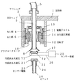
図1は本発明の分注ヘッド部の実施例を示す縦断面図で、1はX−Y方向に移動する支持体、2は支持体1の先端部に設けたケーシングで、分注ヘッド3を収納し、内周面にねじ部4を設けている。この実施例では別個に設けた図示しないポンプにフレキシブルチューブ5で接続するようにしているため分注ヘッド3を中空にしてある。20は分注ヘッドの下端に着脱するピペットである。
11は分注ヘッド3の外周に取り付けた電機子コイルで、図示しない励磁電源に接続されている。12は分注ヘッドにベアリング13を介して回転自由に取り付けた回転子で、内周面に前記電機子コイル11の外周に対向する永久磁石界磁14をそなえ、回転子12が電機子コイル11の外側で回転するアウタロータモータ10を構成している。
【0010】
6は前記回転子12の外周面に設けたねじ部で、ケーシングのねじ部4に螺合させている。71、72は分注ヘッド3の下端に弾性ベロー8を介して取り付けた円弧状永久磁石で、図2に示すように、円弧状永久磁石71、72を接着剤9で周方向に間隔を設けて極性が相互に異なるように環状に配置形成している。21、22はピペット20の上端に取り付けた前記71、72と同様な円弧状永久磁石、23、24はピペット20に取り付けた複数の液面検出用のセンサー電極で、それぞれ円弧状永久磁石21、22に電気的に接続させている。25はセンサー装置、26、27はそれぞれ円弧状永久磁石71、72に接続したセンサー用のリード線である。
【0011】
つぎに作用を説明する。
支持体1がX−Y方向の所定のピペット位置の上に移動すると、図示しないコントローラーにより、電機子コイル11に通電され、永久磁石界磁14を介して回転子12が回転して外周のねじ部6とケーシング2のねじ部4との螺合によって、回転子12がベアリング13で連結された分注ヘッド3とともにケーシング2内を下方に移動して円弧状永久磁石71、72に、ピペット20の円弧状永久磁石21、22を吸着させ、ピペット20が分注ヘッド3に取り付けられる。弾性ベロー8は磁石相互の衝撃をなくして吸着させる。円弧状永久磁石は71、72および21、22はそれぞれ同一径で周方向に極性が異なっているため、分注ヘッド3とピペット20の位置が幾分ずれていても異極同士の位置を合わせて吸着され、一方の磁石が他方の磁石相互の間隙の接着剤9を跨いで吸着されることがない。
【0012】
分注ヘッド3にピペット20が吸着されると、電機子コイル11が逆方向に励磁されて、回転子12を逆回転させ、ねじ部6、4を介して分注ヘッド3を上昇させ、支持体1が所定の分注位置に移動する。
分注位置に移動し、前記ピペットの吸着時と同様にアウタロータモータ10により、分注ヘッド3をサンプリング容器の上に下降させ、サンプリング液をフレキシブルチューブ5から分注ヘッド3の中空内を通してピペット20に送りサンプリング容器に滴下させる。サンプリング容器内の液が、電極23、24まで滴下されると、円弧状永久磁石71、72、21、22を介してリード線26、27が電気的に接続されており、電極23、24がサンプリング液で導通されるとセンサー装置25で検出され、サンプリング液の滴下を停止させる。
サンプリング液の滴下が停止されると、電機子コイル11を逆方向に励磁して回転子12とともに分注ヘッド3を引き上げ、支持体1をつぎの分注位置に移動させる。
【0013】
上記の実施例では、サンプリング液を分注ヘッド3の中空内を通して滴下させるようにしているが、中空内の空気の排出、挿入によりピペット20にサンプリング液を吸入、排出させることもできる。
【0014】
【発明の効果】
このように請求項1の発明は、前後および左右(X−Y軸)方向に移動する支持体に取り付けたケーシング内に、分注ヘッドの外周に取り付けた電機子コイルと、分注ヘッドに回転自由に支持させた回転子によってアウタロータモータを構成させ、回転子の外周とケーシングの内周に設けたねじ部を螺合させ、回転子に連結した分注ヘッドを上下方向に移動させるようにしてあるので、分注ヘッドと操作用のモータが一体となってケーシング内にまとめられ、モータとねじを別個の位置に設ける必要がなく、スペースを省略して小型化できるとともに、動作を確実に行わせ、分注ヘッドの上下移動を円滑にし精度を高め得るなどの効果が得られる。
【0015】
なお請求項2のように、分注ヘッドを中空にすることができ、ピペットとシリンジとを連結させ、ヘッド部分の外側にパイプなどを設ける必要がなく、構造を簡単にすることができる。
【0016】
また、請求項3の発明は、分注ヘッドとピペットに、それぞれ周方向に極性を異ならせて環状に配置した複数の円弧状永久磁石を設けて吸着連結させるので、ピペットの装着を簡単にし、円弧状永久磁石の極同士が確実に吸着して位置決めを行い、分注ヘッドとピペットを精度よく連結させるとともに、ピペットに設けた液面を検出する電極を、円弧状永久磁石を介してセンサー装置に接続させ、磁石相互の吸着、分離をセンサー回路の接点として作用させることができ、固定部に設けたセンサー装置と、着脱されるピペットの電極との接続を簡単確実に行うことができ、レーザーなどによるセンサーを用いないでサンプリング液量の検出ができる効果がある。
【図面の簡単な説明】
【図1】本発明の実施例を示す縦断面図である。
【図2】円弧状永久磁石の配置を示す上面図である。
【符号の説明】
1 支持体
2 ケーシング
3 分注ヘッド
4 ねじ部
5 フレキシブルチューブ
6 ねじ部
8 弾性ベロー
10 アウタロータモータ
11 電機子コイル
12 回転子
13 ベアリング
14 永久磁石界磁
20 ピペット
21、22 円弧状永久磁石
23、24 センサー電極
25 センサー装置
26、27 リード線
71、72 円弧状永久磁石[0001]
TECHNICAL FIELD OF THE INVENTION
The present invention relates to a dispensing apparatus for aspirating / discharging a sampling liquid such as a sample or a reagent to perform liquid separation or dilution, and particularly to a vertical operation of a dispensing head, a pipette attachment / detachment, and a configuration of a sensor device. .
[0002]
[Prior art]
The dispensing head in the dispensing apparatus is attached to an arm or the like that is moved by an XY stage so as to move in the up-down (Z-axis) direction. A gear mechanism consisting of a pinion and a rack connected to the operation motor, a feed screw shaft installed on the side of the operation motor and rotated by gears or belts, or a feed screw shaft connected to the motor shaft; It is composed of a feed screw mechanism composed of combined feed nuts, and is disclosed in the following documents, for example.
[0003]
In this document, as a conventional example, a plurality of pipettes connected by a flexible tube to a syringe provided separately from a head portion, and a gear mechanism including a rack and a pinion are described. A dispensing device that is moved up and down (Z direction) by a drive motor is shown, and the separately provided syringe is integrally formed with each dispensing head so that connection by a flexible tube is omitted. The pipette holding device shown is shown.
[Patent Document 2] Japanese Patent Application Laid-Open No. H11-14631 Although the dispensing device of this document is adapted to change the ejecting position of a pipette tip, the dispensing head is moved by a feed screw rotated by a motor. A shaft and an elevating block screwed to the feed screw shaft are provided, and the dispensing head attached to the elevating block is moved up and down.
[Patent Document 3] Japanese Patent Application Laid-Open No. Hei 6-331632 discloses a technique in which a dispensing head is provided with a stepping motor and a feed screw shaft on its side, and a feed nut is rotated from the stepping motor via a belt. There is shown a dispensing device for vertically moving a feed screw shaft to which a plunger is attached to suck and discharge a liquid to be sampled.
[0004]
[Patent Document 4] Japanese Unexamined Utility Model Publication No. 5-77765 As a liquid level sensor for detecting the liquid level of a sampled liquid in a dispensing apparatus, an electrode of the liquid level sensor is provided on a sampling nozzle via an insulating member, and between the sampling nozzle and the electrode. A detection device is shown in which a short circuit is caused by a sampling liquid to form a conduction circuit.
[0005]
[Problems to be solved by the invention]
As described above, the vertical movement (Z-axis) moving device of the dispensing head has a complicated structure because the drive motor and the vertical moving body are provided separately and connected via the gear mechanism or the screw mechanism. The installation space became large, and assembly and maintenance were troublesome.
Also, in the sampling liquid level detection device, the lead wire is drawn out from the upper part of the sensor electrode provided on the sampling nozzle, so the pipette (nozzle) and the lead wire are integrated, and the dispensing head and Each time the pipette was attached or detached, the lead wire had to be connected to and disconnected from the sensor device, which was troublesome.
[0006]
An object of the present invention is to provide a simple structure of a dispensing head moving device so that a sensor electrode provided on a pipette can be connected to and detached from a dispensing head simultaneously.
[0007]
[Means for Solving the Problems]
For this purpose, a dispensing head that moves in the up-down (Z-axis) direction and attaches a pipette to the tip is provided inside a casing attached to a support that moves in the front-rear and left-right (XY axes) directions. An armature coil is attached to the outer circumference of the injection head, and a rotator that is rotatably supported on the dispense head via a bearing is provided to form an outer rotor motor around the dispense head. The provided screw portion is screwed to a screw portion provided on the inner periphery of the casing, which is a fixed portion.
The dispensing head constituting the fixed shaft of the outer rotor motor may be hollow and used as a passage connecting the pipette and a pump for sucking and discharging the sampling liquid.
[0008]
Further, a sensor electrode for detecting the liquid level of the sampling liquid is provided on a pipette that is attached to and detached from the dispensing head, and a plurality of arc-shaped permanent magnets are mutually polarized at the lower end of the dispensing head and the upper end of the pipette. Are arranged annularly so as to be different in the circumferential direction, the dispensing head and the pipette are connected by the attractive force of the permanent magnet, and the sensor electrode of the pipette is connected to the sensor device on the dispensing head side via this permanent magnet, The sensor circuit is opened and closed by the attachment and detachment of permanent magnets.
[0009]
BEST MODE FOR CARRYING OUT THE INVENTION
FIG. 1 is a longitudinal sectional view showing an embodiment of a dispensing head according to the present invention. Reference numeral 1 denotes a support that moves in the X-Y direction. Reference numeral 2 denotes a casing provided at the tip of the support 1. And a screw portion 4 is provided on the inner peripheral surface. In this embodiment, the dispensing head 3 is hollow because the flexible tube 5 is connected to a separately provided pump (not shown). A pipette 20 is attached to and detached from the lower end of the dispensing head.
An armature coil 11 is attached to the outer periphery of the dispensing head 3 and is connected to an excitation power source (not shown). A rotor 12 is rotatably mounted on the dispensing head via a bearing 13. The rotor 12 has a permanent magnet field 14 facing the outer periphery of the armature coil 11 on the inner peripheral surface. Of the outer rotor motor 10 that rotates outside the motor.
[0010]
Reference numeral 6 denotes a screw portion provided on the outer peripheral surface of the rotor 12, which is screwed to the screw portion 4 of the casing. 2, arc-shaped permanent magnets 71 and 72 are attached to the lower end of the dispensing head 3 via an elastic bellows 8, and as shown in FIG. To form a ring so that the polarities are different from each other. Reference numerals 21 and 22 denote arc-shaped permanent magnets attached to the upper end of the pipette 20, similar to the above-described 71 and 72. Reference numerals 23 and 24 denote a plurality of sensor electrodes for liquid level detection attached to the pipette 20. 22 is electrically connected. 25 is a sensor device, and 26 and 27 are sensor lead wires connected to the arc-shaped permanent magnets 71 and 72, respectively.
[0011]
Next, the operation will be described.
When the support 1 moves above a predetermined pipette position in the X-Y direction, a controller (not shown) energizes the armature coil 11 and the rotor 12 rotates through the permanent magnet field 14 to rotate the outer peripheral screw. The rotor 12 moves downward in the casing 2 together with the dispensing head 3 connected by the bearing 13 by screwing the part 6 and the screw part 4 of the casing 2, and the pipette 20 is moved to the arc-shaped permanent magnets 71 and 72. Are attracted, and the pipette 20 is attached to the dispensing head 3. The elastic bellows 8 absorbs magnets without impact between them. Since the arc-shaped permanent magnets 71, 72 and 21, 22 have the same diameter and different polarities in the circumferential direction, even if the dispensing head 3 and the pipette 20 are slightly displaced, the positions of the dissimilar poles are aligned. One magnet is not attracted across the adhesive 9 in the gap between the other magnets.
[0012]
When the pipette 20 is attracted to the dispensing head 3, the armature coil 11 is excited in the reverse direction, rotates the rotor 12 in the reverse direction, raises the dispensing head 3 via the screw portions 6, 4, and supports The body 1 moves to a predetermined dispensing position.
The dispensing head is moved to the dispensing position, the dispensing head 3 is lowered onto the sampling container by the outer rotor motor 10 in the same manner as when the pipette is sucked, and the sampling liquid is passed from the flexible tube 5 through the hollow of the dispensing head 3 to the pipette 20. And let it drip into the sampling vessel. When the liquid in the sampling container is dropped to the electrodes 23 and 24, the lead wires 26 and 27 are electrically connected via the arc-shaped permanent magnets 71, 72, 21, and 22, and the electrodes 23 and 24 are electrically connected. When the conduction with the sampling liquid is detected, the detection is performed by the sensor device 25, and the dropping of the sampling liquid is stopped.
When the dropping of the sampling liquid is stopped, the armature coil 11 is excited in the reverse direction, the dispensing head 3 is pulled up together with the rotor 12, and the support 1 is moved to the next dispensing position.
[0013]
In the above embodiment, the sampling liquid is dropped through the hollow of the dispensing head 3. However, the sampling liquid can be sucked and discharged to the pipette 20 by discharging and inserting the air in the hollow.
[0014]
【The invention's effect】
As described above, according to the first aspect of the present invention, the armature coil attached to the outer periphery of the dispensing head and the rotation of the dispensing head are provided in the casing attached to the support that moves in the front-rear and left-right (XY axis) directions. The outer rotor motor is constituted by the freely supported rotor, the screw portion provided on the outer periphery of the rotor and the inner periphery of the casing is screwed together, and the dispensing head connected to the rotor is moved vertically. Since the dispensing head and the motor for operation are integrated in the casing, there is no need to provide the motor and screws at separate positions, saving space and reducing size, and ensuring reliable operation. In addition, effects such as smoothing up and down of the dispensing head and improving accuracy can be obtained.
[0015]
It is to be noted that the dispensing head can be made hollow, connecting the pipette and the syringe, and there is no need to provide a pipe or the like outside the head portion, so that the structure can be simplified.
[0016]
According to the invention of claim 3, the dispensing head and the pipette are provided with a plurality of arc-shaped permanent magnets arranged in a circular shape with different polarities in the circumferential direction, and are attracted and connected. The poles of the arc-shaped permanent magnet are securely attracted to each other to perform positioning, accurately connect the pipetting head and the pipette, and the electrode for detecting the liquid level provided on the pipette is a sensor device via the arc-shaped permanent magnet. And the magnets can be attracted and separated from each other as a contact point of the sensor circuit, and the sensor device provided on the fixed part can be easily and reliably connected to the electrode of the detachable pipette. For example, there is an effect that the amount of the sampling liquid can be detected without using a sensor.
[Brief description of the drawings]
FIG. 1 is a longitudinal sectional view showing an embodiment of the present invention.
FIG. 2 is a top view showing an arrangement of arc-shaped permanent magnets.
[Explanation of symbols]
DESCRIPTION OF SYMBOLS 1 Support 2 Casing 3 Dispensing head 4 Thread part 5 Flexible tube 6 Thread part 8 Elastic bellows 10 Outer rotor motor 11 Armature coil 12 Rotor 13 Bearing 14 Permanent magnet field 20 Pipette 21, 22 Arc-shaped permanent magnet 23, 24 Sensor electrode 25 Sensor device 26, 27 Lead wire 71, 72 Arc-shaped permanent magnet