【0001】
【産業上の利用分野】
この発明は、熱風室に赤外線放射体を設けた穀物乾燥機に関する。
【0002】
【従来の技術】
左右の穀粒流下通路の間の熱風室内に、一端側にバーナを連結し他端側を排風機側に延長した燃焼通路を形成すべく遠赤外線放射体を設け、この遠赤外線放射体に熱風を熱風室内に流入させる形態がある(特許文献1)。
【0003】
【特許文献1】
特開2002−48471号公報
【0004】
【発明が解決しようとする課題】
しかるに上記の形態では、バーナの消音効果を目的とするため、バーナの設置構成を遠赤外線放射体と一体化せざるを得ず、構成を複雑化し、ひいては遠赤外線放射体の着脱に配慮がないものとなっている。
【0005】
【課題を解決するための手段】
この発明は上記の欠点を解消しようとするもので、次の技術的手段を講じた。即ち、請求項1に記載の発明は、上部の貯留室、穀物乾燥通路を左右併設し中央側に遠赤外線放射体を配置する熱風室と外側を吸引ファンに通じる排風室に構成した乾燥室と、下部にあって乾燥作用を受けた穀物を集めて貯留室に還元すべく昇降機等の循環移送手段を設ける穀物乾燥機において、熱風室に設ける上記放射体は、入り口側を乾燥機前壁に接続し後面側を乾燥機後壁に接続して設けられ、その上面乃至下面に前後方向に亘ってスリット状に所定幅の開口を形成すると共に、上記前壁の外側にバーナを収容したバーナ風胴を設けてこのバーナ風胴を放射体入り口に連通させたことを特徴とする。
【0006】
機外のバーナ燃焼による火炎は外気とともに熱風となって乾燥機内の放射体内に導入され、この放射体を加熱する一方、放射体の上面乃至下面に前後方向に亘って設けたスリット状開口から出て熱風室に入り、この熱風室で放射体から出る遠赤外線放射熱と相俟って穀物を乾燥する。
【0007】
また、請求項2に記載の発明は、上部の貯留室、穀物乾燥通路を左右併設し中央側に遠赤外線放射体を配置する熱風室と外側を吸引ファンに通じる排風室に構成した乾燥室と、下部にあって乾燥作用を受けた穀物を集めて貯留室に還元すべく昇降機等の循環移送手段を設ける穀物乾燥機において、熱風室に設ける上記放射体は、入り口側を乾燥機前壁に接続し後面側を乾燥機後壁に接続して設けられ、その上面及び下面に前後方向に亘ってスリット状に所定幅の開口を形成すべく、上記放射体を左・右半部で構成した請求項1に記載の穀物乾燥機の構成とする。
【0008】
これによって、放射体を左・右半部の対称形状に形成して機外において左右を連結状に組み付けても、また左右を夫々独立して熱風室に装着しても、軽量となって取扱いが容易となる。
請求項3に記載の発明は、上部の貯留室、穀物乾燥通路を左右併設し中央側に遠赤外線放射体を配置する熱風室と外側を吸引ファンに通じる排風室に構成した乾燥室と、下部にあって乾燥作用を受けた穀物を集めて貯留室に還元すべく昇降機等の循環移送手段を設ける穀物乾燥機において、熱風室に設ける上記放射体は、入り口側を乾燥機前壁に接続し後面側を乾燥機後壁に接続して設けられ、その上面及び下面に前後方向に亘ってスリット状に所定幅の開口を、バーナに近い側において前後適宜長さに形成する請求項1に記載の穀物乾燥機の構成とする。
【0009】
これによって、バーナ火炎と外気との混合による熱風は放射体に前側寄りで主として熱風室に出ると共に遠赤外線放射に寄与し、後側では主として遠赤外線放射に寄与する。
【0010】
【発明の効果】
請求項1に記載の発明は、乾燥機壁の前後に亘って放射体を設け、この放射体にはスリット状開口をこの前後方向に備えるものであるから、バーナによって加熱された放射体からの遠赤外線放射熱とスリット状開口からの熱風とによって、穀物は効率良く乾燥されるものである。
【0011】
又、バーナは乾燥機壁の外側に配置され、乾燥機内の前後に亘る放射体の入り口に連通する構成であるから、放射体着脱はバーナを外すことによって単体で行うことができ、従来のようにバーナ毎の着脱とならないため、簡単容易にこれを行うことができる。
【0012】
また、請求項2に記載の発明は上記の効果に加えて、放射体を左・右半部の対称形状に形成して機外において左右を連結状に組み付けても、また左右を夫々独立して熱風室に装着しても、軽量となって取扱いが容易である。
さらに、請求項3に記載の発明は、前側よりでスリット状開口から熱風が抜けるから、放射体後側寄りに熱風が滞留し難く、当該後寄りの過熱を防止する。
【0013】
【発明の実施の形態】
この発明の一実施の形態を図面に基づき説明する。
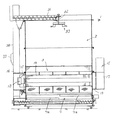
1は穀物乾燥装置の機枠で、内部には貯留タンク2、乾燥室3、集穀室4の順に積み重ねられる。乾燥室3内には、通気性網体5a,5aを対向させて傾斜状の穀物流下通路5,5を形成し、左右一対の穀物流下通路5,5をV字状に形成する。各穀物流下通路5,5の上位側はさらにV字形状を形成すべく左右通路5,5の内側を断面菱形の空間部、即ち後記熱風室6に形成する。なお、該菱形断面の空間形成体のうち下半部は、上記のように通気網体にて形成し、逆V型の上半部は非通気性板材によって形成する。
【0014】
上記穀物流下通路5,5の下部の左右通路の合流部には繰出バルブ7を設けてなる。該繰出バルブ7は断面円形に形成され、正逆回転に伴って外周一部に形成した導入口部7a,7aから穀物を受けいれて、正逆回転連動に伴なって下方の集穀室4に落下させる構成である。
【0015】
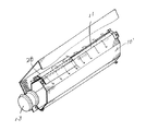
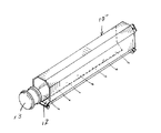
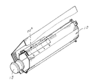
上記乾燥室3の菱形空間部6には、多角形状に形成され乾燥室正面側壁から後面壁に亘る長さに形成された放射体10を機壁前面及び後面に夫々着脱自在に固定して設けている。該放射体10の断面形状は、空間部の菱形断面に相似対応すべく上部の逆V形状と下部のV形状とを短い垂直部で連結する略6角形状とされ、上部尖端と下部尖端とに前後に亘るスリット状の開口11,12を形成する構成であり、実質的に左半部と右半部とを対向させて固定することによって形成されるものである(図3)。なお、左・右半部の前・後壁への取付けは、左右半部を跨ぐ形状の係止具26を前壁に、左・右半部に独立的に設ける係止具27,27を前・後壁に夫々ボルト止めして着脱しうる構成である。
【0016】
上記放射体10の入り口側は、乾燥機正面側に配置するバーナ13からの熱風を受け入れる構成である。即ち、例えば気化型バーナを所定に固定したバーナ風胴14を機体正面側に固定し、該バーナ風胴14と上記放射体10入り口とは連通している。
【0017】
機体の背面側には、吸引ファン15を設け該ファン15の起風によって、上記菱形空間である熱風室6から前記穀物流下通路5,5を経て該通路の各外方に形成される排風路16,16に向け通風すべく構成している。このファン15は、遠心ファンに構成され、そのケーシング17は機体背面側に構成する排風胴18の中央部において、水平軸心P回りに回転自在に取付け変更可能に設けている。即ち、従来ファンケーシング17に対して回転自在に設けたファンブレード19は、上記排風胴18に接続するベルマウス部20の空間部を貫通する支持軸21に支承されていて、実質的にファンケーシング17とは独立して構成されている。なお、支持軸21内端部にはプーリ22を備え、図外モータによって回転駆動されるよう構成している。
【0018】
上記のようにファンブレード19を実質的に乾燥機機体側に支持させファンケーシング17を該機体に対して水平軸芯P回りに回転自在に設けたため、ファンケーシング17に接続する排風ダクト24の向きを上・左右に変更でき、排風先が種々に変更でき乾燥機の設置位置の制約を少なくできる。なお、ファンケーシング17の回転軸芯を水平軸回りとしたが、やや傾斜軸芯とすることも可能である。
【0019】
集穀室4にはその中央に移送螺旋を備えた下部搬送装置25を配設し、前記繰出バルブ7からの繰出穀物を受けて例えば機体正面側方向に移送しうる。
機体の正面側には昇降機30を設け、内部にはバケット30a,30a…を備え、上記下部搬送装置25からの穀物を掬い上げて、上部天井に設ける上部搬送装置31始端に投てきすべく構成している。移送螺旋を備えた上部搬送装置31の終端側における天井中央部には垂下軸32を設け、該垂下軸32には回転拡散盤33を設けている。
【0020】
前記バーナ13の設置構造について、燃焼盤部分とケーシング部分とからなりケーシング部分には気化筒や燃焼用1次空気送風ファン等を内蔵する回転気化型バーナを採用し、これを横姿勢にしてバーナ風胴14に収容し、バーナ火炎は機体内方側に向かうよう設置される。バーナ13正面側の機壁には熱風通過口35を開口している。バーナ13の燃焼火炎は前記吸引ファン15の回転によって乾燥用風となって熱風室6に至る構成である。
【0021】
又バーナ風胴14を囲うように外気導入スリット36aを形成した入り口風胴36を同じく機壁正面に固定し、この前面には乾燥機用コントローラ(制御部)40を設けている。
図10は上記入り口風胴の正面図を示し、コントローラ40の操作盤41部を備えている。この操作盤41面には張込、通風、乾燥、排出、停止の各スイッチ42,43,44,45,46を備え、各種運転モードに切り替わるほか運転停止を司る。また、スイッチ47は緊急スイッチで、当該スイッチ47を操作すると機体運転部の全部を略同時に停止する。
【0022】
これらスイッチ42〜47のほか、張込量を設定する張込量設定スイッチ48、最終仕上げ水分値を設定する水分設定スイッチ49、及び乾燥の速さを籾乾燥の場合は速い・遅い・普通を選択設定でき、他の穀物種類、例えば小麦、大麦等は品種に関連付けて予め設定した乾燥の速さに設定する乾燥設定スイッチ50を備える。更に、乾燥仕上がりを水分値によらないで処理時間によらせるためにタイマ増・減スイッチ51,52を備えている。
【0023】
水分検出手段53は1粒水分計を採用し、所定時間間隔で所定粒数単位で水分測定し各検出結果を平均処理して水分値を算出し、前記操作盤41面の表示部54に検出熱風温度等とともに交代的に表示する構成である。制御部40は併せて1粒水分値から水分バラツキを判定したり、未熟粒の多少を判定できる構成として、これらを3個のLED55,56によって表示している。
【0024】
これら操作盤41面のスイッチ情報等を入力するほか、各種検出センサからの検出情報を入力する乾燥機の制御部40は、前記気化型バーナの燃料供給量を制御したり、穀物の移送系手段を運転制御すべく構成している。
上例の作用について説明する。図外張込ホッパに投入された穀物は、張込スイッチ42をONすることにより駆動する昇降機30、上部搬送装置31等を経て貯留タンク2に張り込まれる。
【0025】
張込完了すると、乾燥作業に移行するが、前段で穀物種類の設定や希望の乾燥仕上げ水分値をスイッチ49及び50によって設定する。
上記の処理が行われて乾燥スイッチ43をONすると、昇降機30、上・下搬送装置25,31、繰出バルブ7等は運転を開始し、かつバーナ13も駆動状態におかれて熱風が乾燥室3の菱形空間である熱風室6入り口に向けて供給されるものとなる。
【0026】
ここで、バーナ火炎は吸引ファン15の回転によって熱風化され、適宜に導入される外気と混合しながら放射体10内に至り、該放射体10を加熱しつつ上部及び下部に形成されたスリット状開口11,12を経て放射体10の外に出る。一方放射体10の加熱によって該放射体10表面から遠赤外線が放射されるが、この熱放射と上記熱風とは共に流下通路5,5にある穀物に作用し、遠赤外線による輻射熱と熱風とで穀物の内部での水分移行が促進され、熱風による水分除去作用を伴って効率的な乾燥作用を行わせることができる。
【0027】
穀物流下通路5,5の前後に亘って遠赤外線放射と熱風による乾燥作用を行わせ、該流下通路5,5を通過した熱風は、排風室16,16を経由して排風されることとなる。
乾燥室3で乾燥作用を受けた穀物は、集穀室4の下部搬送装置25,昇降機30,上部移送螺旋31を経由して再び貯留タンク2に戻され調質作用を受ける。このような行程を繰返し、所定の水分値に達すると乾燥終了するものである。
【0028】
上記のように、熱風室6内においては、放射体10内に入った熱風によって該放射体10が加熱されて遠赤外線が放射され、一方該放射体10内の熱風は、廃熱として乾燥機外に排出されることなく、上下のスリット状開口11,12部から出て放射体10の外部に至るもので、遠赤外線放射による輻射熱と熱風とが穀物流下通路5,5の穀物に作用しこれらの相乗効果で穀物は効率的に乾燥されるものである。
【0029】
上記実施例では、放射体10の断面形状を穀物流下通路5,5の断面形状に略沿わせて構成するものであるから、放射体10からの遠赤外線放射を流下穀物が均等に受け易いものである。
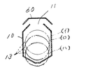
また、上記実施例では、放射体10を構成する構成部材を左右対称形状に構成し、上下に間隔を置いて配置することによってスリット状開口11,12部を構成する形態としたため、上下面双方から熱風が出て放射体10の過熱を防止しうるものであるが、図4に示すように、上面側一方にスリット状開口11を形成して下方側は熱風を排出せず、専らバーナ熱風によって放射体10’下方側加熱を促進したり、逆に図5のように、下面側一方にスリット状開口12を形成して上方側は熱風を排出せず、専らバーナ熱風によって放射体10”上方側加熱を促進する構成とすることができる。なお28は塵埃防止用遮蔽部材である。このような配置は穀物流下通路5,5の配置構成のほか、バーナ13の放射体10に対する上下位置関係に基づき、熱風の温度分布を配慮しながら適宜に採用するものである。
【0030】
例えば放射体10入り口に対してバーナ13位置を標準中央位置(図6(イ))から下方に下げて配置する場合は(同図(ロ))、下方側の放射体10加熱が促進されるため、上方側にスリット状開口11を構成して熱風を上方側に引き出させ全体として熱風のバランスをとることができる。なお、更にバーナ13を下方に位置させるときは(同図(ハ))、一部放射体10下方側から熱風が溢流する関係で、上記下部スリット状開口12の機能を備え、従ってこの場合も上面側にスリット状開口11を配設するとよい。この場合にはスリット状開口11部の上面を適宜間隔離れて覆うように山形の覆板60を設けていいる。このように覆板60を構成することによって、スリット状開口11部からの熱風が噴出状態で直接熱風室6に至ることがなく、一旦該覆板60で反射されてからその勢いを緩和されつつ熱風室6に至るもので、局部的な乾燥むら等を生じさせない。
【0031】
バーナ13の配置位置を逆に上方側に上げて配置する場合は上記と逆の関係に設けるとよい。
また図7、及び図8はスリット状開口11’,12’を放射体10のバーナ13配置側に近い前側に形成して、バーナ13からの熱風をその直後で放射体10加熱に供するものとし、併せてその熱風を放射体10の外側に移行させるものである。このように構成すると、比較的高温状態の熱風の一部は放射体10加熱後直ちに放射体10から出る関係となって、比較的温度の安定した熱風が放射体10後半を加熱する一方、熱風室6への熱風の供給が安定する。
【0032】
図12は穀物流下通路5,5の面する側の一部をガラス部材61で構成することによって遠赤外線放射の吸収効率を向上させるものである。即ち、通気性部材によって構成する穀物流下通路5,5の一部をガラス部材61に構成する。図例では穀物流下通路5,5の下部側をガラス部材61に構成して遠赤外線放射熱の吸収促進を図っているが、ガラス部材61の配設位置は上方にあってその後熱風を流通させる形態とすると、穀物の水分移行を促進した後に熱風によって水分除去することとなって効率的である。
【0033】
図13,14は、バーナ13を装着するバーナ風胴14と乾燥機の前側壁に形成する外気導入孔80との関係に照らし、該導入孔80が必要な乾燥機形態と、この導入孔が不要もしくは制限する乾燥機形態とに仕分けてバーナ風胴14a、14bを構成することによって、当該バーナ風胴14a又は14bの装着をもって必要な外気導入孔形態を得ようとするものである。即ち、熱風室6入り口孔を形成する乾燥前壁1Aに、第1仕様のバーナ風胴14aと第2仕様のバーナ風胴14bを同一の装着構成、例えば上下左右同位置にボルト装着用孔81を形成し、乾燥機前壁1Aには第1仕様に対応すべく外気導入孔80を形成する。第1仕様のバーナ風胴14aは、外気導入孔80を用いて外気を導入する形態であるから、これら導入孔80を全面開放しうるよう施蓋状としないものとし、一方第2仕様のバーナ14bは、これら外気導入を不要とする形態であるから装着導入孔を施蓋状となるようフランジ部81面積を大きく形成するものである。このように構成することによって、第1または第2仕様の選択をバーナ風胴によって決定すれば、併せて外気導入仕様を決定でき後の施蓋工程を省略できて便利である。なお、外気導入孔形態を一部施蓋状とすることも容易に対応できるものである。上記第1仕様の例としては、上記実施形態のような放射体を備える乾燥機に適用し、更に内部の温度分布状態を確認しながら導入孔形態を種々に変更設定できる形態としてもよい。
【0034】
図16は貯留タンク2に配設される張棒70の構成を示すものである。従来、一端に螺子部aを形成し、他端を係合用に折り曲げ形成した張棒bを前後乃至左右の貯留部タンクc壁に架け渡して一端の螺子部aにナット部材eを螺合して固定する形態(図15)があるが、補強を兼ねる桟部材fにスペーサ部材gが乗り上げて締め付けに不便であった。このため、丸棒筒形状の張棒70をその両端部でボルト部材71によって締め付け固定するにあたり、スペーサ部材gに代えて円筒形状のカラー72を介して締め付けする構成とすることによって、桟部材73に乗り上げることもなくなり、かつ構成を簡単に然も取付けの容易化がはかれるものとなった。
【0035】
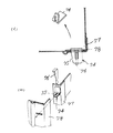
又、図18は貯留部タンク2等のコーナ部を各形成する壁部を係合固定するためのくさび体の構成に係る。従来平面視直角に連結するタンク壁hの各端部には接合用の平面視L型の接合部材iを延設し、このうち重合する一面にL型くさび受けjを貫通状に設け、そのタンク外側面に位置する貫通孔kにくさびmを挿通して固定する構成である(図17)が、矢印(ニ)方向にのみ引っ張り作用を伴う形態となるから、例えば他の接合部nに隙間が生じるなどの欠点があった。
【0036】
然るに図18に示すものは、くさび受け74の片面をテーパ状75に形成する構成とすることによって、くさび76の打ち込みに伴い、他側のL型接合金具77,78を重合状に圧接させる構成となっている。
図19は、穀物乾燥機の例えば昇降機30途中に配設する前記水分検出手段53を利用して穀物排出を自動停止する構成の改良に係るものである。即ち、乾燥機の前記移送螺旋を収容する上部搬送装置31の始端部側に開閉シャッタ82を介して排出シュート83により機外適所に排出しうる構成としている。この排出作動は前記操作盤41に配設した排出スイッチ45の操作によるものである。この穀物排出は繰出バルブ7よりも高面に穀物が存在するときは定常流的に排出されて所定の流量が確保されるが、繰出バルブ7以下になると排出量は漸次減少し、ついには全排出を終えるものとなるが、機内にはどうしても残粒を生じて所定未満の穀粒は排出され得ない。このため従来のように目視判定して作業者の勘にたよって排出を停止すべく停止スイッチ46を操作するようになっていた。
【0037】
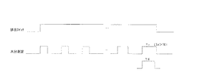
上記水分検出手段52には一粒取込機構84を備え、一対の電極ロール85,85間に順次供給しうる構成とし、このロール間の電気的抵抗値によって穀物水分に換算している。
ところで、この排出指令信号が供給されると、水分検出手段53を作動する。予め設定した粒数を測定する時間を測定し、この基準時間Tsを記憶し、一定時間後に水分検出手段53を動作させ同様に定められた粒数を測定する時間を測定して、この時間Tnと上記時間Tsとの比較によって穀物排出終了情報を得ようとするものである。具体的には、上記基準時間Tsと測定時間Tnとの比Tn/Tsが所定値(E)以下に達すると自動的に排出スイッチをオフの状態にし、排出終了となす構成である(図20)。
【0038】
このように構成すると、個々の機械のばらつきにより水分検出手段53への取込粒数に要する時間がまちまちであっても、排出工程に入ると所定粒数の確認を行い得て精度高く排出管理を行うことができる。
また、図21に示すものは別例であり、上記の所定粒数における排出中測定時間Tnが、予め設定した所定時間TEと比較の結果、Tn≧TEの条件のときは排出終了信号を出力しようとするものである。なお、このときの予め設定する時間TEは、標準的な排出処理量を知って理論的に求める方法もよいが、実測を行い所定粒数取り込みに要する時間TE1,TE2…TEnの平均値TEaveをもって上記条件式にあてはめるようにすると乾燥機個々のばらつきに影響されない値を採用することができて便利である。
【0039】
更に、図22は乾燥用熱風の流通に伴い舞い上がる塵埃を捕捉する手段の構成に係るものである。即ち、穀物流下通路85,85の外側を熱風室86に構成し内側を吸引ファン87に通じる排風室88に構成するものである。加えてバーナ(図示せず)の噴風口は左右側熱風室86の片方側に構成され、他方の熱風室86には繰出バルブ90と下部搬送装置91の移送螺旋との間隔部を左右流通能に構成して当該片方の熱風室86に供給される熱風を分岐供給可能に構成している。このように構成した熱風の供給経路途中であって、傾斜板92からなる仕切り部材の下方空間93の一、即ち熱風を分岐供給しうる位置に浮遊塵埃を捕捉する捕捉手段としての捕捉ボックス94を備えている。このように構成することにより、熱風室86から排風室88に熱風が供給される間に穀物中に浮遊する塵埃類は、捕捉ボックス94に受けられて後に回収される。
【図面の簡単な説明】
【図1】穀物乾燥機の全体側断面図である。
【図2】穀物乾燥機の正面図である。
【図3】放射体の斜視図である。
【図4】異なる例の放射体の斜視図である。
【図5】異なる例の放射体の斜視図である。
【図6】放射体正断面図である。
【図7】更に異なる例の放射体の斜視図である。
【図8】更に異なる例の放射体の斜視図である。
【図9】吸引ファン部の(イ)背面図、及び(ロ)側面図である。
【図10】操作盤正面図である。
【図11】制御ブロック図である。
【図12】別例を示す穀物乾燥機の正断面図である。
【図13】バーナ風胴の装着状態を示す正面図である。
【図14】バーナ風胴の装着状態を示す(イ)正面図、及び(ロ)側断面図である。
【図15】従来の張棒装着状態を示す断面図である。
【図16】改良後の張棒装着状態を示す(イ)正面図、及び(ロ)A−A断面図である。
【図17】従来のタンク側壁装着状態を示す平断面図である。
【図18】改良後のタンク側壁装着状態を示す(イ)平断面図、及び(ロ)斜視図である。
【図19】フローチャートである。
【図20】タイムチャートである。
【図21】タイムチャートである。
【図22】異なる例を示す穀物乾燥機の正断面図である。
【符号の説明】
2…貯留室、3…乾燥室、5,5…穀物乾燥通路、6…熱風室、10…放射体、11,12…スリット状開口、15…吸引ファン[0001]
[Industrial applications]
The present invention relates to a grain dryer provided with an infrared radiator in a hot air chamber.
[0002]
[Prior art]
A far-infrared radiator is provided in the hot air chamber between the left and right grain downflow passages so as to form a combustion passage having a burner connected to one end and extending to the exhaust fan side at the other end. Is introduced into a hot air chamber (Patent Document 1).
[0003]
[Patent Document 1]
JP-A-2002-48471
[Problems to be solved by the invention]
However, in the above-described embodiment, in order to reduce the noise of the burner, the installation configuration of the burner must be integrated with the far-infrared radiator. It has become something.
[0005]
[Means for Solving the Problems]
The present invention has been made to solve the above drawbacks, and has taken the following technical measures. In other words, the invention according to claim 1 is a drying chamber comprising an upper storage chamber, a hot air chamber in which a grain drying passage is provided on the left and right sides and a far-infrared radiator is arranged in the center, and an exhaust air chamber in which the outside communicates with a suction fan. In a grain dryer provided with a circulating transfer means such as an elevator for collecting and drying the grains subjected to the drying action at the bottom and returning the collected grains to the storage chamber, the radiator provided in the hot air chamber has an entrance side at the front wall of the dryer. The burner has a rear surface connected to the rear wall of the dryer, and has an opening of a predetermined width formed in a slit shape extending in the front-rear direction on an upper surface or a lower surface thereof, and a burner housed outside the front wall. A wind tunnel is provided, and the burner wind tunnel communicates with the radiator entrance.
[0006]
The flame generated by the burner combustion outside the machine becomes hot air together with the outside air and is introduced into the radiator in the dryer. The radiator is heated, while exiting from the slit-shaped opening provided on the upper or lower surface of the radiator in the front-rear direction. In the hot air chamber, the grain is dried in combination with the far-infrared radiation heat emitted from the radiator.
[0007]
Further, the invention according to claim 2 is a drying chamber comprising an upper storage chamber, a hot air chamber in which a grain drying passage is provided on the left and right side and a far-infrared radiator is arranged on the center side, and an exhaust air chamber in which the outside communicates with a suction fan. In a grain dryer provided with a circulating transfer means such as an elevator for collecting and drying the grains subjected to the drying action at the bottom and returning the collected grains to the storage chamber, the radiator provided in the hot air chamber has an entrance side at the front wall of the dryer. The radiator is composed of left and right halves in order to form an opening of a predetermined width in the form of a slit in the front and rear direction on the upper and lower surfaces of the radiator. The grain dryer according to claim 1 is configured.
[0008]
This allows the radiator to be made symmetrical with the left and right halves and assembled right and left outside the machine in a connected manner, or even if the left and right sides are independently installed in a hot air chamber, it will be lightweight and handleable Becomes easier.
The invention according to claim 3 is a drying chamber configured as a storage chamber at the upper part, a hot air chamber in which a grain drying passage is provided on the left and right side and a far-infrared radiator is arranged on the center side, and an exhaust air chamber that communicates with a suction fan on the outside, In the grain dryer provided with a circulating transfer means such as an elevator to collect the dried grains at the bottom and return to the storage room, the radiator provided in the hot air chamber has the entrance side connected to the front wall of the dryer. The rear surface side is connected to the rear wall of the dryer, and an opening of a predetermined width is formed in a slit shape on the upper surface and the lower surface thereof in the front-rear direction and the front and rear sides are formed to have an appropriate length in the front-rear direction on the side close to the burner. The configuration of the grain dryer described above is adopted.
[0009]
As a result, the hot air resulting from the mixture of the burner flame and the outside air mainly exits the hot air chamber toward the radiator and contributes to far-infrared radiation, and mainly contributes to far-infrared radiation on the rear side.
[0010]
【The invention's effect】
According to the first aspect of the present invention, since the radiator is provided on the front and back of the dryer wall and the radiator is provided with a slit-shaped opening in the front-rear direction, the radiator is heated from the radiator heated by the burner. Grains are efficiently dried by far-infrared radiation heat and hot air from the slit-shaped openings.
[0011]
Moreover, since the burner is arranged outside the dryer wall and communicates with the entrance of the radiator extending in the front and rear in the dryer, the radiator can be detached and attached alone by removing the burner. This can be easily and easily performed because the burner does not need to be attached or detached.
[0012]
Further, in addition to the above-mentioned effects, the invention according to claim 2 forms the radiator in a symmetrical shape of the left and right halves and assembles the left and right portions outside the machine in a connected manner. Even when installed in a hot air chamber, it is lightweight and easy to handle.
Furthermore, according to the third aspect of the present invention, since the hot air escapes from the slit-shaped opening from the front side, the hot air hardly stays toward the rear side of the radiator, and the rear side overheating is prevented.
[0013]
BEST MODE FOR CARRYING OUT THE INVENTION
An embodiment of the present invention will be described with reference to the drawings.
Reference numeral 1 denotes a machine frame of a grain drying apparatus, in which a storage tank 2, a drying chamber 3, and a grain collecting chamber 4 are stacked in this order. In the drying chamber 3, the air-permeable nets 5 a, 5 a are opposed to each other to form inclined grain distribution lower passages 5, 5, and a pair of left and right grain distribution lower passages 5, 5 are formed in a V-shape. On the upper side of each of the grain distribution lower passages 5, 5, the inside of the left and right passages 5, 5 is formed in a space having a rhombic cross section, that is, a hot air chamber 6, which will be described later, so as to form a V-shape. The lower half of the rhombus-shaped space forming body is formed of a ventilation net as described above, and the inverted V-shaped upper half is formed of a non-breathable plate.
[0014]
A delivery valve 7 is provided at the junction of the left and right passages below the grain distribution lower passages 5,5. The feed valve 7 is formed in a circular cross section, and receives grains from inlet ports 7a, 7a formed in a part of the outer periphery with forward and reverse rotations, and moves to the lower grain collecting chamber 4 with forward and reverse rotations. It is a configuration to be dropped.
[0015]
A radiator 10 which is formed in a polygonal shape and has a length extending from the front side wall to the rear wall of the drying chamber 3 is detachably fixed to the front and rear surfaces of the machine wall in the rhombic space 6 of the drying chamber 3. ing. The cross-sectional shape of the radiator 10 is a substantially hexagonal shape in which the upper inverted V shape and the lower V shape are connected by a short vertical portion so as to correspond to the rhombic cross section of the space portion. In this configuration, slit-shaped openings 11 and 12 are formed in the front and rear directions, and are formed by substantially fixing the left half and the right half with facing each other (FIG. 3). When attaching the left and right halves to the front and rear walls, a locking tool 26 that straddles the left and right halves is provided on the front wall, and locking tools 27 and 27 that are independently provided on the left and right halves are provided. It is a structure that can be attached and detached by bolting to the front and rear walls, respectively.
[0016]
The entrance side of the radiator 10 is configured to receive hot air from a burner 13 disposed on the front side of the dryer. That is, for example, a burner wind tunnel 14 having a vaporized burner fixed thereto is fixed to the front side of the fuselage, and the burner wind tunnel 14 communicates with the entrance of the radiator 10.
[0017]
A suction fan 15 is provided on the rear side of the fuselage, and the wind generated by the fan 15 causes exhaust air to be formed from the hot air chamber 6, which is the diamond-shaped space, through the grain distribution lower passages 5, 5 to each outside of the passage. It is configured to ventilate to the roads 16, 16. This fan 15 is configured as a centrifugal fan, and its casing 17 is rotatably mounted around a horizontal axis P at a central portion of an air discharge duct 18 formed on the rear side of the fuselage. That is, the fan blade 19 which is rotatably provided with respect to the conventional fan casing 17 is supported by a support shaft 21 which penetrates through a space portion of a bell mouth portion 20 connected to the exhaust duct 18 and is substantially a fan. It is configured independently of the casing 17. A pulley 22 is provided at the inner end of the support shaft 21 and is configured to be rotationally driven by a motor (not shown).
[0018]
As described above, the fan blades 19 are substantially supported on the dryer body side, and the fan casing 17 is provided rotatably around the horizontal axis P with respect to the dryer body. The direction can be changed upward, left and right, the exhaust destination can be changed in various ways, and restrictions on the installation position of the dryer can be reduced. Although the rotation axis of the fan casing 17 is around the horizontal axis, it may be slightly inclined.
[0019]
In the grain collecting room 4, a lower conveying device 25 provided with a transfer spiral at the center thereof is provided, and can receive the fed grain from the feeding valve 7 and transfer the grain to, for example, the front side of the machine body.
An elevator 30 is provided on the front side of the fuselage, and buckets 30a, 30a,... Are provided inside, so that the grain from the lower transport device 25 is scooped up and thrown to the beginning of the upper transport device 31 provided on the upper ceiling. ing. A hanging shaft 32 is provided at the center of the ceiling at the end side of the upper transfer device 31 provided with a transfer spiral, and a rotating diffusion plate 33 is provided on the hanging shaft 32.
[0020]
Regarding the installation structure of the burner 13, a rotary evaporative burner which includes a combustion plate part and a casing part, and incorporates a vaporizing cylinder, a primary air blowing fan for combustion, and the like is employed in the casing part. The burner flame is housed in the wind tunnel 14, and is installed so as to face the inside of the aircraft. A hot air passage 35 is opened in the machine wall in front of the burner 13. The combustion flame of the burner 13 is turned into a drying wind by the rotation of the suction fan 15 and reaches the hot air chamber 6.
[0021]
An entrance wind tunnel 36 having an outside air introduction slit 36a formed so as to surround the burner wind tunnel 14 is also fixed to the front of the machine wall, and a dryer controller (control unit) 40 is provided on the front.
FIG. 10 shows a front view of the entrance wind tunnel, which includes an operation panel 41 of the controller 40. The operation panel 41 is provided with switches 42, 43, 44, 45, and 46 for squeezing, ventilation, drying, discharging, and stopping, and switches to various operation modes and stops operation. The switch 47 is an emergency switch, and when the switch 47 is operated, all of the machine operating units are stopped almost simultaneously.
[0022]
In addition to these switches 42 to 47, the setting amount 48 for setting the filling amount, the setting switch 49 for setting the final finishing moisture value, and the speed of drying are set to fast / slow / normal for paddy drying. Other grain types, for example, wheat, barley, etc., which can be selected and set, are provided with a drying setting switch 50 for setting a predetermined drying speed in association with the variety. Further, timer increase / decrease switches 51 and 52 are provided in order to make the drying finish depend on the processing time without depending on the moisture value.
[0023]
The moisture detecting means 53 employs a one-grain moisture meter, measures the moisture in a predetermined number of grains at predetermined time intervals, averages each detection result, calculates a moisture value, and detects the moisture value on the display unit 54 of the operation panel 41. In this configuration, the information is displayed alternately with the hot air temperature and the like. The control unit 40 also displays these by three LEDs 55 and 56 so as to determine the water variation from the water value of one grain and to determine the number of immature grains.
[0024]
In addition to inputting switch information on the operation panel 41 and the like, and inputting detection information from various detection sensors, the control unit 40 of the dryer controls the fuel supply amount of the evaporative burner, Is configured to control operation.
The operation of the above example will be described. The grain put into the outside stuffing hopper is stuffed into the storage tank 2 via the elevator 30 driven by turning on the stuffing switch 42, the upper conveying device 31, and the like.
[0025]
When the filling is completed, the process shifts to the drying operation, but the setting of the grain type and the desired dry finish moisture value are set by the switches 49 and 50 in the previous stage.
When the drying switch 43 is turned on after the above processing is performed, the elevators 30, the upper and lower transport devices 25 and 31, the delivery valve 7 and the like start operating, and the burner 13 is also driven, so that the hot air is blown into the drying chamber. 3 is supplied toward the entrance of the hot air chamber 6 which is a diamond-shaped space.
[0026]
Here, the burner flame is hot weathered by the rotation of the suction fan 15 and reaches the radiator 10 while being mixed with the appropriately introduced outside air, while heating the radiator 10 and forming slits formed in the upper and lower portions. The radiation exits the radiator 10 through the openings 11 and 12. On the other hand, when the radiator 10 is heated, far-infrared rays are radiated from the surface of the radiator 10, and both the heat radiation and the hot air act on the grains in the downflow passages 5 and 5 to generate radiant heat by the far-infrared rays and hot air. Moisture transfer inside the grain is promoted, and an efficient drying action can be performed with the action of removing water by hot air.
[0027]
The drying operation by the far-infrared radiation and the hot air is performed before and after the grain distribution lower passages 5, 5, and the hot air passing through the lower passages 5, 5 is exhausted through the exhaust air chambers 16, 16. It becomes.
The grain subjected to the drying action in the drying chamber 3 is returned to the storage tank 2 again through the lower conveying device 25, the elevator 30 and the upper transfer spiral 31 of the grain collecting chamber 4, and is subjected to the refining action. Such a process is repeated, and drying is completed when a predetermined moisture value is reached.
[0028]
As described above, in the hot air chamber 6, the radiator 10 is heated by the hot air entering the radiator 10 to emit far-infrared rays, while the hot air in the radiator 10 is dried as waste heat. Without being discharged to the outside, it exits from the upper and lower slit-shaped openings 11 and 12 and reaches the outside of the radiator 10, and radiant heat and hot air due to far-infrared radiation act on the grains in the grain distribution lower passages 5 and 5. These synergistic effects allow the grain to be dried efficiently.
[0029]
In the above embodiment, since the cross-sectional shape of the radiator 10 is configured to substantially conform to the cross-sectional shape of the grain distribution lower passages 5, 5, the falling grain is more likely to receive far-infrared radiation from the radiator 10 evenly. It is.
Further, in the above-described embodiment, the constituent members forming the radiator 10 are formed in a symmetrical shape, and the slit-shaped openings 11 and 12 are formed by arranging them vertically, so that both upper and lower surfaces are formed. However, as shown in FIG. 4, a slit-shaped opening 11 is formed on one side of the upper surface and hot air is not exhausted on the lower side. The lower side of the radiator 10 'is promoted by heating, or conversely, as shown in FIG. 5, a slit-shaped opening 12 is formed on one side of the lower side, and the upper side does not discharge hot air. It is possible to adopt a configuration that promotes the upper side heating.In addition, 28 is a dust-preventing shielding member.This arrangement includes the arrangement configuration of the grain distribution lower passages 5,5 and the vertical position of the burner 13 with respect to the radiator 10. Based on the relationship , While appropriately considering the temperature distribution of the hot air.
[0030]
For example, when the burner 13 is positioned lower than the standard center position (FIG. 6A) with respect to the entrance of the radiator 10 (FIG. 6B), heating of the lower radiator 10 is promoted. Therefore, the slit-shaped opening 11 is formed on the upper side, and the hot air is drawn out to the upper side, so that the hot air can be balanced as a whole. In addition, when the burner 13 is further positioned below ((c) in the figure), the function of the lower slit-shaped opening 12 is provided because the hot air partially overflows from below the radiator 10. It is also preferable to provide a slit-shaped opening 11 on the upper surface side. In this case, a mountain-shaped cover plate 60 is provided so as to cover the upper surface of the slit-shaped opening 11 at appropriate intervals. By configuring the cover plate 60 in this manner, the hot air from the slit-shaped opening 11 does not directly reach the hot air chamber 6 in a spouting state, but is temporarily reflected by the cover plate 60 and the momentum is reduced. It reaches the hot air chamber 6 and does not cause local uneven drying.
[0031]
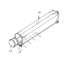
When the burner 13 is to be disposed with the position of the burner 13 raised upward, the burner 13 may be provided in a relationship opposite to the above.
7 and 8 show that the slit-shaped openings 11 'and 12' are formed on the front side of the radiator 10 near the burner 13 arrangement side, and the hot air from the burner 13 is used for heating the radiator 10 immediately thereafter. In addition, the hot air is transferred to the outside of the radiator 10. With such a configuration, a part of the hot air in a relatively high temperature state comes out of the radiator 10 immediately after the radiator 10 is heated. The supply of hot air to the chamber 6 is stabilized.
[0032]
FIG. 12 shows an improvement in the absorption efficiency of far-infrared radiation by forming a part of the side facing the grain distribution lower passages 5 and 5 with a glass member 61. That is, a part of the grain distribution lower passages 5, 5 constituted by the air-permeable member is constituted by the glass member 61. In the illustrated example, the lower side of the grain distribution lower passages 5 and 5 is configured as a glass member 61 to promote absorption of far-infrared radiation heat, but the glass member 61 is disposed at an upper position and hot air is circulated thereafter. When it is in a form, it is efficient because water is removed by hot air after promoting water transfer of the grain.
[0033]
13 and 14 show the relationship between the burner wind tunnel 14 on which the burner 13 is mounted and the outside air introduction hole 80 formed in the front side wall of the dryer. By configuring the burner wind tunnels 14a and 14b separately from unnecessary or restricted dryer forms, it is intended to obtain the required external air introduction hole form by mounting the burner wind tunnels 14a or 14b. That is, the first specification burner wind tunnel 14a and the second specification burner wind tunnel 14b have the same mounting configuration on the front drying wall 1A that forms the entrance hole of the hot air chamber 6, for example, the bolt mounting holes 81 at the same position in the upper, lower, left and right directions. Is formed, and an outside air introduction hole 80 is formed in the front wall 1A of the dryer to conform to the first specification. Since the burner wind tunnel 14a of the first specification has a form in which outside air is introduced using the outside air introduction hole 80, the burner wind turbine 14a of the second specification is not formed in a cover shape so that the introduction hole 80 can be fully opened. 14b is a form in which the introduction of outside air is not required, so that the area of the flange portion 81 is formed large so that the mounting introduction hole has a lid shape. With this configuration, if the selection of the first or second specification is determined by the burner wind tunnel, the external air introduction specification can be determined at the same time, and the subsequent lidding step can be omitted, which is convenient. In addition, it is possible to easily cope with a configuration in which the external air introduction hole is partially covered. As an example of the above-mentioned first specification, the present invention may be applied to a dryer having a radiator as in the above-described embodiment, and may be a form in which the form of the introduction hole can be changed and set variously while checking the internal temperature distribution state.
[0034]
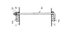
FIG. 16 shows the configuration of the tongue 70 provided in the storage tank 2. Conventionally, a threaded member b is formed at one end, and a tension rod b bent at the other end for engagement is hung over front and rear or left and right storage tank c walls, and a nut member e is screwed to the threaded portion a at one end. Although there is a form (FIG. 15) in which the spacer member g rides on the cross member f which also serves as reinforcement, it is inconvenient for tightening. For this reason, when tightening and fixing the round bar-cylinder-shaped tension bar 70 at both ends by the bolt members 71, the cross member 73 is tightened via the cylindrical collar 72 instead of the spacer member g. In addition, there is no need to ride on the vehicle, and the configuration is simplified, but the mounting is facilitated.
[0035]
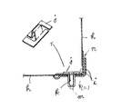
FIG. 18 relates to a configuration of a wedge body for engaging and fixing walls forming respective corners of the storage tank 2 and the like. Conventionally, an L-shaped joining member i for joining in plan view is extended at each end of the tank wall h connected at a right angle in plan view, and an L-shaped wedge receiver j is provided in a penetrating shape on one surface to be overlapped. The wedge m is inserted into and fixed to the through-hole k located on the outer surface of the tank (FIG. 17). There were drawbacks such as the formation of gaps.
[0036]
However, the one shown in FIG. 18 has a configuration in which one surface of the wedge receiver 74 is formed in a tapered shape 75 so that the L-shaped joints 77 and 78 on the other side are press-contacted in an overlapping manner as the wedge 76 is driven. It has become.
FIG. 19 relates to an improvement in the structure for automatically stopping grain discharge by using the moisture detecting means 53 disposed in the middle of the grain dryer, for example, the elevator 30. That is, the dryer is configured such that it can be discharged to an appropriate place outside the machine by the discharge chute 83 via the opening / closing shutter 82 at the start end side of the upper conveying device 31 accommodating the transfer spiral of the dryer. This discharge operation is performed by operating a discharge switch 45 provided on the operation panel 41. This cereal discharge is discharged in a steady flow when the cereal is present on a surface higher than the delivery valve 7 and a predetermined flow rate is secured. Although the discharge is completed, residual grains are inevitably generated in the machine, and a grain smaller than a predetermined amount cannot be discharged. For this reason, the stop switch 46 is operated to stop the discharge according to the visual judgment and the intuition of the operator as in the prior art.
[0037]
The moisture detecting means 52 is provided with a single grain take-in mechanism 84, which is configured so as to be able to sequentially supply between a pair of electrode rolls 85, 85, and converts the grain moisture into a grain moisture by an electric resistance value between the rolls.
By the way, when the discharge command signal is supplied, the water detecting means 53 is operated. A predetermined time for measuring the number of grains is measured, this reference time Ts is stored, and after a certain time, the moisture detecting means 53 is operated to measure a time for measuring the number of grains similarly determined. And the time Ts to obtain grain discharge end information. Specifically, when the ratio Tn / Ts between the reference time Ts and the measurement time Tn reaches a predetermined value (E) or less, the discharge switch is automatically turned off, and the discharge is completed (FIG. 20). ).
[0038]
With this configuration, even if the time required for the number of particles taken in to the moisture detecting means 53 varies due to variations in individual machines, a predetermined number of particles can be confirmed in the discharge process, and the discharge control can be performed with high accuracy. It can be performed.
FIG. 21 shows another example. When the measurement time Tn during discharge at the above-mentioned predetermined number of particles is compared with a predetermined time TE set in advance, a discharge end signal is output when the condition of Tn ≧ TE is satisfied. What you are trying to do. Note that the preset time TE at this time may be theoretically obtained by knowing the standard discharge processing amount. However, the average value TE ave of the times TE1, TE2,. By applying the above to the above conditional expression, it is convenient to adopt a value that is not affected by variations in the individual dryers.
[0039]
Further, FIG. 22 relates to a configuration of means for catching dust soaring with the flow of hot air for drying. That is, the outside of the grain distribution lower passages 85 and 85 is configured as a hot air chamber 86, and the inside is configured as an exhaust air chamber 88 communicating with a suction fan 87. In addition, the air outlet of the burner (not shown) is formed on one side of the left and right hot air chambers 86, and the other hot air chamber 86 is provided with a space between the delivery valve 90 and the transfer spiral of the lower transfer device 91 in the right and left flow direction. And the hot air supplied to the one hot air chamber 86 can be branched and supplied. In the middle of the hot air supply path configured as described above, a capturing box 94 as capturing means for capturing floating dust is placed in one of the lower spaces 93 of the partition member composed of the inclined plate 92, that is, at a position where hot air can be branched and supplied. Have. With this configuration, the dust floating in the grains while hot air is supplied from the hot air chamber 86 to the exhaust air chamber 88 is received by the capture box 94 and is collected later.
[Brief description of the drawings]
FIG. 1 is an overall side sectional view of a grain dryer.
FIG. 2 is a front view of the grain dryer.
FIG. 3 is a perspective view of a radiator.
FIG. 4 is a perspective view of a radiator of another example.
FIG. 5 is a perspective view of a radiator of another example.
FIG. 6 is a front sectional view of a radiator.
FIG. 7 is a perspective view of a radiator of still another example.
FIG. 8 is a perspective view of a radiator of still another example.
9A is a rear view of the suction fan unit, and FIG. 9B is a side view of the suction fan unit.
FIG. 10 is a front view of the operation panel.
FIG. 11 is a control block diagram.
FIG. 12 is a front sectional view of a grain dryer showing another example.
FIG. 13 is a front view showing a mounted state of the burner wind tunnel.
14A is a front view and FIG. 14B is a sectional side view showing a mounted state of the burner wind tunnel.
FIG. 15 is a cross-sectional view showing a state in which a conventional stick is attached.
16 (a) is a front view and FIG. 16 (b) is a cross-sectional view taken along the line AA, showing a state in which the post is improved.
FIG. 17 is a plan sectional view showing a conventional tank side wall mounted state.
18A is a plan cross-sectional view and FIG. 18B is a perspective view showing the tank sidewall mounted state after the improvement.
FIG. 19 is a flowchart.
FIG. 20 is a time chart.
FIG. 21 is a time chart.
FIG. 22 is a front sectional view of a grain dryer showing a different example.
[Explanation of symbols]
2 ... storage room, 3 ... drying room, 5, 5 ... grain drying passage, 6 ... hot air room, 10 ... radiator, 11, 12 ... slit-shaped opening, 15 ... suction fan