【0001】
【発明の属する技術分野】
この発明は自動車の加減速状態を後続車両に知らせる、アクセルランプシステムに関する。
【0002】
【従来の技術】
従来、自動車の加減速を後続車に知らす装置としては、例えば持開2000−289524号公報に記載のように自動車のアクセルを直前の踏み込み角度に対して、所定角度に戻した場合にオクに成るワンウエイクラッチを設け、アクセルスイッチと点滅手段に、左右それぞのストップランプを2分割して前記に接続されたストップランプをバッテリを通して、接続した事を特徴とする自動車の加減速警報装置が提案されている。しかし、アクセルペタルを踏んでいるかアクセルペタルを戻しているかを後続車両に知らせる、アクセルランプシステムは今まで知られていなかった。
【0003】
【発明が解決しようとする課題】
今までの自動車はブレーキ操作しない限りストップランプは点灯せず、アクセルペタルを離しエンジンブレーキが効いて減速状態を後続車に示せないために、追突しそうに成り車間距離が縮み自動車の流れが悪く、渋滞ぎみに成る問題がある。
【0004】
【課題を解決するための手段】
自動車後部に後方車両から確認できる、青色ランプと黄色ランプの一体型ランプを取り付け、青色ランプはアクセルペタルが踏まれて加速時と平行速時に点灯する。次に、黄色ランプはアクセルペタルから足が離れると、一般道路では0.5秒から2秒間に1回から5回の点滅をした後点灯する。高速道路は0.5秒から3秒間に1回から10回の点滅した後点灯する。一般道路で点滅回数をふやす場合は、手動で可変リレーボックスの可変ボリュムで行なう。
【0005】
運転者がアクセルペタルから足を離すと、黄色ランプが点滅した後点灯するのでエンジンブレーキで走行中の後、ブレーキング操作が行なわれる可能性があると判断出来るので、後続車はブレーキを踏む態勢が早くから出来る。
【0006】
運転者が走行中アクセルペタルに足がかかっている限り、青色ランプは点灯しており後続車からは確認でき、一応、前車はブレーキングはしない事が確実に判断出来る。
【0007】
【発明の実施の形態】
発明の実施の形態を実施例にもとづき図面を参照にして説明する。図1、は実施の形態による自動車の追突防止の、アクセルランプシステムのブロック図である。図2、はこの発明の自動車の追突防止アクセルランプ装置を自動車後部に付けた正面図である。
【0008】
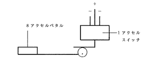
図3、はアクセルペタル支点にアクセルスイッチ1を取り付けて配線で、図1の可変リレーボックス2に送り、さらに後部のアクセルランプ4に送り点滅と点灯を表示する。
【0009】
本発明で使用するアクセルスイッチは、市販のマイクロスイッチを利用したものである。又、アクセルスイッチに入る電源は、イグニッションキーより取り出す。
【0010】
図1において作用を説明すると、イグニッションキー5から電源を取出してアクセルスイッチ1に接続、さらに可変リレーボックス2とスピードメータ3にも接続してアクセルランプ4を点滅と点灯の表示する。
【0011】
図2は、アクセルランプ、6と7の正面図で、青色ランプ6はアクセルオンの状態で点灯する。又、黄色ランプ7の2個のランプはアクセルオフに成ると、スピードメータ3と、可変リレーボックス2からの電流で、一般道路は5キロメートル時から60キロメートル時迄は、0.5秒から2秒までの間に1回から5回、点滅をした後点灯する。又、高速道路で60キロメートル時を超えると0.5秒から3秒までの間に1回から10回の点滅をした後点灯をする。又、可変リレーボックス2の可変ボリュムでは手動で点滅回数を変える事が出来る
【0012】
図3は、アクセメペタル8の支点にアクセルスイッチ1を取り付けて、配線で可変リレーボックス2に電流を送る装置である。
【0013】
【発明の効果】
本発明は以上の様にアクセルペタル操作だけで、ブレーキ操作を行なう以前の挙動が確実に判るので、追突防止の効果がある。
【図面の簡単な説明】
【図1】自動車の追突防止アクセルランプシステムのブロック図である。
【図2】自動車の追突防止アクセルランプの正面図である。
【図3】自動車のアクセルペタルとアクセルスイッチの図面である。
【符号の説明】
1 アクセルスイッチ
2 可変リレーボックス
3 スピードメータ
4 アクセルランプ
5 イグニッションキ
6 青色ランプ
7 黄色ランプ
8 アクセルペタル
9 ブラケット[0001]
TECHNICAL FIELD OF THE INVENTION
The present invention relates to an accelerator lamp system for notifying a following vehicle of an acceleration / deceleration state of an automobile.
[0002]
[Prior art]
Conventionally, as a device for informing the following vehicle of the acceleration / deceleration of the vehicle, when the accelerator of the vehicle is returned to a predetermined angle with respect to the immediately preceding depression angle, as described in, for example, Japanese Unexamined Patent Publication No. 2000-289524, it becomes ok. A vehicle acceleration / deceleration warning device has been proposed in which a one-way clutch is provided, and a stop lamp for each of the left and right is divided into two parts by an accelerator switch and blinking means, and the stop lamps connected to the above are connected through a battery. ing. However, an accelerator lamp system that informs a following vehicle whether or not the accelerator pedal is being depressed or returned is not known until now.
[0003]
[Problems to be solved by the invention]
Until the brakes are operated, the stop lamp does not light up until now, the accelerator pedal is released, the engine brake is effective, and the deceleration state cannot be shown to the following vehicle, so it is likely to collide, the inter-vehicle distance decreases, the flow of the car is poor, There is a problem of congestion.
[0004]
[Means for Solving the Problems]
At the rear of the car, an integrated lamp of blue and yellow lamps, which can be seen from the vehicle behind, is installed. The blue lamp is lit when the accelerator pedal is depressed and when accelerating and parallel speed. Next, when the foot is separated from the accelerator petal, the yellow lamp flashes once to five times every 0.5 to 2 seconds on a general road, and then turns on. The highway lights up after blinking 1 to 10 times in 0.5 to 3 seconds. To increase the number of blinks on an ordinary road, manually use the variable volume of the variable relay box.
[0005]
When the driver removes his / her foot from the accelerator petal, the yellow light flashes and then turns on, so it is possible to judge that there is a possibility that a braking operation may be performed after driving with the engine brake, so the following vehicle is ready to step on the brake Can be done early.
[0006]
As long as the driver's foot is on the accelerator pedal while the vehicle is running, the blue lamp is lit and can be checked from the following vehicle, and it can be determined for the time being that the preceding vehicle will not brake.
[0007]
BEST MODE FOR CARRYING OUT THE INVENTION
Embodiments of the present invention will be described based on examples with reference to the drawings. FIG. 1 is a block diagram of an accelerator lamp system for preventing a rear-end collision of a vehicle according to an embodiment. FIG. 2 is a front view of the rear-end collision preventing accelerator lamp device for a vehicle according to the present invention.
[0008]
In FIG. 3, an accelerator switch 1 is attached to an accelerator petal fulcrum, and wiring is sent to the variable relay box 2 of FIG. 1 and further sent to an accelerator lamp 4 at the rear to display blinking and lighting.
[0009]
The accelerator switch used in the present invention utilizes a commercially available microswitch. The power supplied to the accelerator switch is taken out from the ignition key.
[0010]
The operation will be described with reference to FIG. 1. The power is taken out from the ignition key 5 and connected to the accelerator switch 1, and further connected to the variable relay box 2 and the speedometer 3 so that the accelerator lamp 4 blinks and lights up.
[0011]
FIG. 2 is a front view of the accelerator lamps 6 and 7. The blue lamp 6 is turned on when the accelerator is on. When the two lamps of the yellow lamp 7 are released from the accelerator, the current from the speedometer 3 and the variable relay box 2 indicates that the ordinary road will travel from 0.5 seconds to 2 hours from 5 km to 60 km. Turns on after blinking once to five times before the second. When the vehicle speed exceeds 60 km on the highway, the light flashes once to 10 times from 0.5 seconds to 3 seconds and then turns on. In the variable volume of the variable relay box 2, the number of blinks can be manually changed.
FIG. 3 shows an apparatus in which an accelerator switch 1 is attached to a fulcrum of an accesspetal 8 and current is sent to a variable relay box 2 by wiring.
[0013]
【The invention's effect】
As described above, the present invention has an effect of preventing a rear-end collision, because the behavior before the brake operation is performed can be reliably determined only by the accelerator pedal operation.
[Brief description of the drawings]
FIG. 1 is a block diagram of an accelerator lamp system for preventing a rear-end collision of an automobile.
FIG. 2 is a front view of a rear-end collision prevention accelerator lamp of a vehicle.
FIG. 3 is a drawing of an accelerator pedal and an accelerator switch of an automobile.
[Explanation of symbols]
1 Accelerator switch 2 Variable relay box 3 Speedometer 4 Accelerator lamp 5 Ignition key 6 Blue lamp 7 Yellow lamp 8 Accel petal 9 Bracket