JP2004174342A - Coating apparatus and coating method - Google Patents
Coating apparatus and coating method Download PDFInfo
- Publication number
- JP2004174342A JP2004174342A JP2002342005A JP2002342005A JP2004174342A JP 2004174342 A JP2004174342 A JP 2004174342A JP 2002342005 A JP2002342005 A JP 2002342005A JP 2002342005 A JP2002342005 A JP 2002342005A JP 2004174342 A JP2004174342 A JP 2004174342A
- Authority
- JP
- Japan
- Prior art keywords
- piston
- sleeve
- coating
- coating apparatus
- displacement
- Prior art date
- Legal status (The legal status is an assumption and is not a legal conclusion. Google has not performed a legal analysis and makes no representation as to the accuracy of the status listed.)
- Pending
Links
Images


Abstract
Description
【0001】
【発明の属する技術分野】
本発明は、プラズマディスプレイパネル(以下「PDP」と称す)の蛍光体層形成に関する塗布装置および塗布方法に関する。
【0002】
【従来の技術】
プラズマディスプレイパネルの蛍光体層を形成する方法として、スクリーン印刷方式やディスペンサー方式,電解ジェット方式,インクジェット方式,フォトレジスト方式などがある。これらの方法を用いてR(赤),G(緑),B(青)の蛍光体層が背面板のリブ間に形成される。
【0003】
近年、プラズマディスプレイパネルの高精細化、高輝度化に対応するために様々なリブ形状が考案されている。そのなかでも、図11に示すようなボックス型リブは、クロストーク問題の解決や、発光面積の向上などの利点から注目されている。
【0004】
【特許文献1】
特許第2679036号公報
【特許文献2】
特開2002−021715号公報
【特許文献3】
特開2001−015021号公報
【0005】
【発明が解決しようとする課題】
しかしながら、前述する従来の方法では、精度良く高速にボックス型リブに蛍光体層を形成することは難しいと考える。その理由を以下に説明する。
【0006】
例えば、スクリーン印刷方式の場合、近年の画面サイズの大型化、高精細化により用意されるべきスクリーン版はかなり大型のもの、且つ、微細な構造を有する物になる。すると、スクリーン版の伸縮や位置決め誤差が生じやすく精度良く塗布することは必然的に難しくなる。
【0007】
また、インクジェット方式の場合、極微量を精度よく塗布することは可能であるが、1ショット当りの塗布量が少ないため、生産タクトの面から不利である。また、塗布材料をインクにするためには、固形分である蛍光体の濃度を下げなくてはならず、そのため、パネルの輝度がある一定量から上がらないという問題を有する。
【0008】
また、フォトレジスト方式の場合、感光性蛍光体フィルムをリブ間に埋め込み形成したい蛍光体層のみを露光し、露光しない部分は洗い流すため、ある程度精度は、よく蛍光体層を形成できる。しかしながら、R(赤)G(緑)B(青)の3色ごとに蛍光体フィルムの埋め込み、露光、洗浄作業という一連の作業が必要なまた、工程数が増えるうえに材料コストが高くなるという問題が生じる。
【0009】
また、ディスペンサー方式の場合、微量に間欠で塗布することは可能であるが、精度よく高速で塗布することは難しい。例えば、図11に示すような従来のエアパルス式のディスペンサーの場合、水頭差による吐出量のバラツキ、吐出圧脈動による吐出量のバラツキ、流体の粘度低下による吐出量のバラツキなどの問題が存在しており、精度よく塗布することが出来ない。これらの問題を解決するために、水頭差、温度変化などの影響を予めコンピュータにプログラミングしておき、エアパルスの制御を行うなどしているが、制御系が複雑化して根本的な解決策にはなっていない。
【0010】
また、エアパルス式のディスペンサーの場合、ノズル先端を塗布面に近接させた状態でノズルから材料を吐出し、その材料が基板に転写されることによって塗布が行われている。そこで、ボックス型リブに塗布する際、ノズル先端部をリブ高さより下げた場合、塗布後ノズル先端に材料が付着し、それが材料の糸引きやタレの要因となり精度よく塗布できない。逆に、リブ高さより上げて塗布する場合、リブ頂部に余分な材料がつかないよう塗布量を調整して塗布することは非常に困難である。
【0011】
これらの観点からも、従来のエアパルス式のディスペンサーでボックス型リブに塗布することは困難であった。すなわち、ディスペンサー方式でボックス型リブに高速に塗布するためには、ノズル先端とその対向面を十分に離した状態で、材料をノズル先端から吐出飛翔させる技術が必要であると言える。
【0012】
これら従来のディスペンサーの欠点を克服するために、特許文献1に開示されるディスペンサーを用いれば、高速で塗布することが可能であると考えられる。しかしながら、このディスペンサーにおいて、ペースト材料をボックス型リブに間欠に、始点から終点まで精度よく均一量、均一濃度で塗布する方法、且つ、吐出口と対向面である基板との距離を広い間隔に保持し、塗布材料を飛翔させて塗布する方法については、開示されていない。
【0013】
本発明は、上記従来の問題点を解決するもので、プラズマディスプレイパネルのボックス型リブに精度良く、均一量且つ均一濃度の蛍光体をディスペンサー方式により高速塗布する塗布装置および塗布方法を提供するものである。
【0014】
【課題を解決するための手段】
上記の目的を達成するために、本願第1の発明の塗布装置は、ピストンとハウジングを相対的に移動させる第一のアクチュエーターと、前記ピストンの少なくとも一部を収納し軸方向に貫通した空間を有するスリーブと、前記スリーブと前記ハウジングを相対的に移動させる第二のアクチュエーターと、前記ピストン、前記スリーブ及び前記ハウジングで形成されるポンプ室と外部とを連絡する流体の吸入口と吐出口より構成される塗布装置であって、前記ピストンと前記スリーブを相対的に逆方向に動作させる時間をT1、前記ピストンを下降させる時間をT2、スリーブを上昇させる時間をT3としたとき、T1>T2、T3>T2であることを特徴とする。
【0015】
このとき、T1,T2,T3の時間関係が、T1>T3>T2であると好適である。
【0016】
また、本願第1の発明の塗布装置において、流体吐出時間T2がT2<5msecであると好適である。
【0017】
また、本願第1の発明の塗布装置において、ボックス型リブのガラス基板面から前記吐出口までの距離δが、δ>100μmであると好適である。
【0018】
また、本願第1の発明の塗布装置において、ボックス型リブにおいて1つのボックスの縦方向を縦リブ、横方向を横リブと定義し、その縦リブ横リブのうち、短い方の長さをLと、1滴の吐出量をVとした時に、ボックス型リブのガラス基板面から前記吐出口までの距離δが、δ>1.5V/πL2であると好適である。
【0019】
また、本願第1の発明の塗布装置において、ピストンとスリーブの相対的な変位量を変えることでポンプ室の容量を制御し、ノズルから流体を間欠に吐出飛翔させることで基板のリブ形状に依存しない塗布を可能にすると好適である。
【0020】
また、本願第1の発明の塗布装置において、基板に塗布する際、始点や終点付近においてはピストンとスリーブの相対変位量を漸次変化させると好適である。
【0021】
また、本願第1の発明の塗布装置において、ピストンとスリーブの変位からなる変位波形において、その波形に微小な振動を加えると好適である。
【0022】
また、本願第1の発明の塗布装置において、ピストンとスリーブの変位波形の一区間に超音波発振子による振動を加えると好適である。
【0023】
更に、本願第1の発明の塗布装置において、流体を塗布する際、塗布装置のZ軸方向の変位はゼロであると好適である。
【0024】
一方、本願第1の発明の塗布方法は、ピストンとハウジングを相対的に移動させながら、前記ピストンの少なくとも一部を収納し軸方向に貫通した空間を有するスリーブと前記ハウジングを相対的に移動させることで、流体が前記ピストン、前記スリーブ及び前記ハウジングで形成されるポンプ室から吐出口を経て吐出される塗布方法であって、
前記ピストンと前記スリーブを相対的に逆方向に動作させる時間をT1、前記ピストンを下降させる時間をT2、スリーブを上昇させる時間をT3としたとき、T1>T2、T3>T2であることを特徴とする。
【0025】
【発明の実施の形態】
以下、図面を参照しながら、本実施形態について説明する。
【0026】
図1は、ボックス型リブの基板例の概要を示すものである。この様なリブ形状の形成方法としては、厚膜印刷やサンドブラスト法などがある。例えば、サンドブラスト法の場合、ガラスペーストをガラス基板1にスクリーン印刷などにより塗布した後、この上に、感光性レジストを塗布、露光、現像した後に、レジスト膜が形成されていない箇所をサンドブラストにより除去することで、ボックス型リブ2が形成される。42インチパネルの場合、例えばボックス型リブの幅は、縦0.63mm,横0.26mm程度の大きさである。
【0027】
このような、ボックス型リブ2に蛍光体ペーストを塗布する際、図2に示す塗布装置を使用する。主な装置構成としては、矢印X−X’にディスペンサー3を移動させる移動部5、矢印Y−Y’に基板4を移動させる搬送部6、矢印Z−Z’にディスペンサー3を移動させる移動部7、移動部5及び7と搬送部6を制御する制御ボックス8、蛍光体材料を供給するエアー圧制御部9からなる。そして、基板4と吐出口のクリアランス、相対位置を決めて、ディスペンサー3により基板4に蛍光体ペーストを間欠に塗布する。
【0028】
図2に示すディスペンサー3は、ピストンとハウジングを相対的に移動させる第一のアクチュエーターと、このピストンの少なくとも一部を収納し軸方向に貫通した空間を有するスリーブと、このスリーブとハウジングを相対的に移動させる第二のアクチュエーターと、前記ピストン、前記スリーブ、前記ハウジングで形成されるポンプ室と外部とを連絡する流体の吸入口と吐出口より構成される。
【0029】
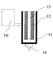
第一及び第二のアクチュエーターは、超磁歪素子や圧電素子等の電磁歪素子から構成されており、Z軸方向に高速、微小変位することが出来る。図3にディスペンサー先端部の断面図を示す。
【0030】
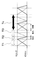
図3をもとに、ペースト材料の流れを説明すると蛍光体ペーストは、材料供給部10から外枠11とスリーブ12の間を通りノズル先端部に供給される。そして、スリーブ12とピストン13の連動した動作により蛍光体ペーストがノズル14より間欠に吐出される。このスリーブ12とピストン13の動作の一例を図4、変位波形を図5に示す。
【0031】
これら図4、図5をもとに吐出メカニズムについて説明する。
【0032】
まず、スリーブ12とピストン13が上下逆方向に動作する第1区間T1では、スリーブ12が下降することにより外枠11、スリーブ12、ピストン13で囲まれた擬閉空間すなわちポンプ室15が形成される(交換行程)。次に、ピストン13が下降する第2区間T2では、擬閉空間に閉じ込められた一定量の蛍光体ペーストがポンプ室15より吐出口14を経て吐出される(吐出行程)。更に、第3区間T3では、ピストン13は一定高さのままで、スリーブ12が上昇することにより再び蛍光体ペーストがポンプ室15に供給される(吸入行程)。そして、第3区間T3から又第1区間T1へと移り、このサイクルすなわち塗布周期Tcを繰り返すことによって蛍光体ペーストの連続吐出が可能となる。
【0033】
本塗布装置における第1区間T1は、材料交換行程であり、第2区間T2は材料吐出行程、第3区間T3は材料吸入行程である。各行程T1,T2,T3のそれぞれ必要な時間は、次の通りである。
【0034】
まず、吸入行程T3は、他の行程より長い時間が必要である。その理由は、ポンプ室15には圧力差で材料が充填するが、仮に充填時間が短ければ、充填量が不足し空打ちとなる。このため、最低限の充填時間が必要であるためである。吐出行程T2は、短いほど大きなピーク圧力を発生でき、流体を飛翔させやすく出来る。圧電素子などのアクチュエーターを用いれば、T2<1msecは可能である。交換行程T1も、スリーブ12の下降により強制的に流体をポンプ室15に流入できるので十分に小さくできる。
【0035】
これらのことから、T1,T2,T3の時間関係はT1>T2、T3>T2であり、より望ましい関係は、T1>T3>T2である。また、生産タクトから考えて吐出時間T2は、T2<5msecであることが望ましい。更に、応答性の高い素子や電源を用いれば塗布周期Tcは短縮可能である。
【0036】
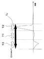
また、本発明の塗布装置で間欠塗布を可能にしているのは、図5に示す様な、スリーブ12とピストン13の変位波形により、ノズル先端部に負圧と正圧が交互に生じるためである。ディスペンサー3のノズル先端部での発生圧力を図6に示す。
【0037】
まず、スリーブ12を上昇させる第3区間T3では大きな負圧が発生し、スリーブ12とピストン13が上下逆方向に動作する第1区間T1では徐徐に圧力が回復し、ピストン13が下降する第2区間T2では大きな正圧が発生する。このように、スリーブ12とピストン13の動作のみで負圧が発生するので、従来のディスペンサーのように液切れをさせるために、塗布直後Z軸方向にディスペンサー自身を持ち上げなくともよい。このため、Z軸方向の変位はゼロとなるので、蛍光体ペーストを間欠に高速で塗布することが可能となる。
【0038】
このノズル先端部に起こる正圧と負圧のサイクルにより、蛍光体ペーストに対して適切なノズル径とノズル長を選択すれば、蛍光体ペーストをノズル14から飛翔させることが出来る。その結果、ディスペンサー3では、インクジェットのように塗布材料を飛翔させることが出来るので、ボックス型リブ2はもちろん基板面のリブ形状に依存しない塗布が可能となる。ボックス型リブのリブ高さは通常100μm以上あるが、本塗布装置の吐出口(ノズル14)とガラス基板面との距離δをδ>100μm上げて塗布すればよい。
【0039】
また、ノズルから材料を飛翔させて塗布する際、液滴を完全な球体と考えるとボックス型リブに一回で入れる球体の直径は、リブ幅より大きくなってしまう。しかしながら、実際には液滴の自重があるので、液滴は回転楕円体の形で塗布されると考えられる。このことから、最低でもノズルと基板間の距離は楕円体長軸の2倍以上、リブ幅が楕円体短軸の2倍以上の長さを有していれば、リブ頂部にペーストが付着することなく塗布することが出来る。
【0040】
この状態を図7に示す。1滴当りの体積をV(mm3)、リブ幅をL(mm)とし、回転楕円体の長軸をa、短軸をbとすると、その体積Vは、V=4πab2/3である。ガラス基板からノズルまでの高さδは、δ>2a必要でありL=2bとすると、δ>2a=2×(3V/4πb2)=1.5V/πL2と言う関係式が導かれる。少なくともこの関係式を満たすようにノズル14とガラス基板との距離を離して塗布する必要がある。
【0041】
図8は、ペースト材料の飛翔性を改善するために、ピストンとスリーブの変位波形を改善したものである。
【0042】
ペースト材料を吐出する第2区間T2では、スリーブ12とピストン13両方を下降させる。これにより、図5の変位波形より吐出圧力を上げることが出来る。そして、第2区間T2の直後スリーブ12とピストン13を同時に上昇することにより、図5の変位波形よりポンプ室15には大きな負圧が発生する。このように、スリーブ12とピストン13を同時に動作させることで正圧と負圧をよりポンプ室15に発生させて、更に高粘度の材料でも間欠にノズルから飛翔させて吐出することが出来る。本発明における塗布装置は変位波形を変えることにより、吐出性を自在に変化させることが出来るので、幅広い粘度の塗布材料に対応できると言える。
【0043】
一方、このディスペンサーにおけるスリーブ12とピストン13の変位波形の変位量を変えることで、従来のディスペンサー方式や電解ジェット方式などが不得意であった始点での塗布量の均一性を向上させることが出来る。
【0044】
塗布の始点で起こる問題として、塗布量が中間点のものに対して少ないという問題が存在する。その一因として材料特性の問題が考えられる。蛍光体ペーストは、往々にしてチクソ性を有するものであり、高いせん断力をかけた場合、粘度が低下するという性質を有している。そのために、このようなペースト材料を用いた場合、吐出開始から定常状態に入るまでの間、塗布量が一定になりにくい。この解決方法として従来のディスペンサー方式等では、エアー圧制御部を設けて吐出量の安定化を図ってきた。しかしながらこの方法では、装置が大掛かりになりマルチヘッド化が困難である、制御系が複雑になるなど問題点が存在する。
【0045】
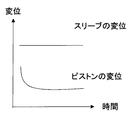
この課題を解決する方法として、本発明では、ディスペンサー3のスリーブ12とピストン13の変位量を漸次変化させて吐出量を制御する。それぞれの変位量の関係を、図9に示す。
【0046】
図9に示すように塗布開始直後は、ピストン13の変位量を多く取り、1ショット当りの塗布量を増やし、定常状態に入った後では、ピストン13の変位量を一定に保つ。すなわち、一時的に1ショット当りの塗布量を増やすことにより、チクソ性の影響による塗布量不足を解決する。このことによって塗布の始点から終点まで一定量の塗布を可能にしている。
【0047】
なお、ピストン13の変位量を一定に保ち、スリーブ12の変位量を漸次変化させることによっても1ショット当りの吐出量を変化させることが出来るので、この方法によっても始点での塗布量不均一性を解決することが出来る。
【0048】
このように、スリーブ12とピストン13の変位波形や変位量を変えることによりリブ形状に依存しなく、様々なサイズのパネルに塗布することが可能となる。この点はスクリーン印刷のようにサイズごとのスクリーン版を用意しなくとも良く、優れた利点であると言える。
【0049】
また、変位波形を変えることにより、塗布量を一定に保つだけでなく、一定濃度の材料を塗布することも可能となる。例えば、蛍光体ペーストに含まれる粒子の沈降を防ぐために、第1区間T1などで微小な振動を与える波形をスリーブ12、ピストン13の変位波形(図5や図8)に加える。このことで、ペースト材料の流動性があがり沈降を防ぐことができるので均一濃度の塗布が可能となる。
【0050】
また、微小な振動により材料にせん断力が掛かり、粘度を一時的に下げるので、吐出性を高めると言う効果も期待できる。なお、吐出に影響がないほどの振動をT1だけでなく、T2,T3区間においても加える方法も有効であると考えられる。
【0051】
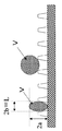
また、材料の吐出性を上げるために、スリーブ12とピストン13の変位波形に微小な振動を加える方法だけでなく、超音波発振子を利用した方法も考えられる。これは図10のように、ディスペンサーの材料供給口またはディスペンサー内に超音波発振子16を取り付ける。このような装置を利用した例は、特許文献3のようなものがあるが、この場合は粒子の沈降を防ぐという至極当然の装置であると考える。
【0052】
この装置での使用される超音波発振子16の役割はこれだけでない。すなわち、スリーブ12とピストン13の動きと同期させることで、材料供給をスムーズにすることができ、吐出性を上げることが出来る。例えば、ピストン13が持ち上がる第3区間T3において超音波発振子16で振動を与え、材料にせん断力を掛けることにより、材料の粘度を一時的に下げる。これにより、第3区間T3や第1区間T1での、ポンプ室15への材料供給がスムーズに行え、ピストン13でその直後に吐出する。当然、粒子の沈降も防止するので均一濃度の材料を塗布することが出来る。
【0053】
一方、ボックス型リブに蛍光体ペーストを間欠に飛翔させて精度よく塗布するためにはノズル径もリブ幅より小さくしなくてはならない。このことにより、ノズルの目詰まりが発生しやすいという問題が生じる。しかしながら、スリーブ12とピストン13の変位波形に微小な振動を加える方法や、超音波発振子による振動を加えることにより、ペーストの流動性を高める事が出来るのでノズルでの目詰まりが起こらないようになると言う効果も期待できる。
【0054】
この点からも、変位波形に微小な振動を加えることや変位波形に同期して超音波発振子で振動を与えることは非常に有用な手段であると考えられる。
【0055】
この蛍光体塗布装置は、シングルヘッドでもよいが、生産タクトを考えるのならマルチヘッドのディスペンサーが望ましいと考えられる。その場合も、このスリーブ12とピストン13からなる2重ピストン構造を使うことは出来る。すなわち、ノズル部を多穴にしても良いし、スリーブとピストンをペンシルサイズに小型化し複数本並べてもよい。
【0056】
また、リブ間の適切な位置に塗布する為に、リブを認識するCCDカメラ等の認識部を備えた機構にすることで各リブ間により、正確に均一量塗布することが出来ると考えられる。
【0057】
【発明の効果】
本発明の塗布装置および塗布方法によれば、ディスペンサーの構造をスリーブとピストンと言う2重ピストン構造とし、そのスリーブとピストンの変位波形に工夫を施すことで、スクリーン印刷やインクジェット法より、精度良く均一量、且つ、均一濃度のペースト材料を高速で塗布することが可能となる。
【図面の簡単な説明】
【図1】本発明の実施形態に係るボックス型リブの基板例を示す概要図
【図2】本発明の実施形態に係る主な塗布装置の構成を示す概略図
【図3】本発明の実施形態に係るディスペンサーのノズル部の断面図
【図4】本発明の実施形態に係るディスペンサーのスリーブとピストンの動きを示す図
【図5】本発明の実施形態に係るディスペンサーのスリーブとピストンの変位波形図
【図6】本発明の実施形態に係るディスペンサーのノズル先端部で生じる圧力を示す図
【図7】本発明の実施形態に係るリブに塗布する際の液滴の形状を示す概念図
【図8】本発明の実施形態に係るディスペンサーのスリーブとピストンの変位波形図
【図9】本発明の実施形態に係るスリーブとピストンの変位量を漸次変化させる例を示す図
【図10】本発明の実施形態に係る超音波発振子の取り付け例を説明する図
【図11】従来のエアパルス式ディスペンサーを示す図
【符号の説明】
1,4 ガラス基板
2 ボックス型リブ
3 ディスペンサー
5,7 移動部
6 搬送部
8 制御ボックス
9 エアー圧供給部
10 材料供給部
11 外枠
12 スリーブ
13 ピストン
14 ノズル
15 ポンプ室
16 超音波発振子[0001]
TECHNICAL FIELD OF THE INVENTION
The present invention relates to a coating apparatus and a coating method for forming a phosphor layer of a plasma display panel (hereinafter, referred to as “PDP”).
[0002]
[Prior art]
As a method for forming a phosphor layer of a plasma display panel, there are a screen printing method, a dispenser method, an electrolytic jet method, an ink jet method, a photoresist method, and the like. Using these methods, R (red), G (green), and B (blue) phosphor layers are formed between the ribs on the back plate.
[0003]
In recent years, various rib shapes have been devised in order to cope with higher definition and higher luminance of a plasma display panel. Among them, a box-shaped rib as shown in FIG. 11 has attracted attention because of its advantages such as solving the crosstalk problem and improving the light emitting area.
[0004]
[Patent Document 1]
Japanese Patent No. 2679036 [Patent Document 2]
Japanese Patent Application Laid-Open No. 2002-021715 [Patent Document 3]
Japanese Patent Application Laid-Open No. 2001-015021
[Problems to be solved by the invention]
However, it is considered difficult to form a phosphor layer on a box-type rib accurately and at high speed by the above-described conventional method. The reason will be described below.
[0006]
For example, in the case of the screen printing method, the screen plate to be prepared due to the recent increase in screen size and definition has a considerably large size and a fine structure. Then, expansion and contraction of the screen plate and positioning errors are likely to occur, and it is inevitably difficult to apply with high accuracy.
[0007]
In addition, in the case of the ink jet system, it is possible to apply a very small amount with high precision, but the application amount per shot is small, which is disadvantageous in terms of production tact. In addition, in order to use the coating material as ink, the concentration of the phosphor, which is a solid content, must be reduced, and therefore, there is a problem that the brightness of the panel does not increase from a certain amount.
[0008]
In the case of the photoresist method, only the phosphor layer to be formed by embedding the photosensitive phosphor film between the ribs is exposed, and the unexposed portion is washed away, so that the phosphor layer can be formed with a high degree of accuracy. However, a series of operations of embedding, exposing, and cleaning phosphor films for each of three colors of R (red), G (green), and B (blue) is required, and the number of steps is increased, and the material cost is increased. Problems arise.
[0009]
Further, in the case of a dispenser method, it is possible to apply a small amount intermittently, but it is difficult to apply it at high speed with high accuracy. For example, in the case of a conventional air pulse type dispenser as shown in FIG. 11, there are problems such as variations in the discharge amount due to a difference in water head, variations in the discharge amount due to discharge pressure pulsation, and variations in the discharge amount due to a decrease in fluid viscosity. And cannot be applied accurately. In order to solve these problems, the effects of head difference, temperature change, etc. are programmed in advance in a computer and air pulses are controlled, but the control system is complicated, and the fundamental solution is is not.
[0010]
In the case of an air pulse type dispenser, a material is ejected from a nozzle in a state where the tip of the nozzle is close to a coating surface, and the material is transferred to a substrate to perform coating. Therefore, when applying to the box-shaped rib, if the tip of the nozzle is lower than the rib height, the material adheres to the tip of the nozzle after the application, which causes threading or sagging of the material, and cannot be applied accurately. Conversely, when applying with a height higher than the rib height, it is very difficult to adjust the amount of application so that extra material does not stick to the top of the rib.
[0011]
From these viewpoints, it has been difficult to apply a conventional air pulse type dispenser to the box type rib. That is, to apply the dispenser method to the box-type ribs at high speed, it can be said that a technique is required in which the material is ejected from the nozzle tip while the tip of the nozzle and the facing surface are sufficiently separated.
[0012]
If the dispenser disclosed in
[0013]
SUMMARY OF THE INVENTION The present invention solves the above-mentioned conventional problems, and provides a coating apparatus and a coating method for applying a high-precision, uniform amount and a uniform concentration of a phosphor to a box-shaped rib of a plasma display panel by a dispenser method. It is.
[0014]
[Means for Solving the Problems]
In order to achieve the above object, a coating apparatus according to the first aspect of the present invention includes a first actuator that relatively moves a piston and a housing, and a space that accommodates at least a part of the piston and penetrates in an axial direction. A second actuator for moving the sleeve and the housing relative to each other, and a suction port and a discharge port for a fluid that communicates a pump chamber formed by the piston, the sleeve and the housing with the outside. T1> T2, where T1 is a time for moving the piston and the sleeve relatively in the opposite direction, T2 is a time for lowering the piston, and T3 is a time for raising the sleeve. T3> T2.
[0015]
At this time, it is preferable that the time relationship between T1, T2, and T3 is T1>T3> T2.
[0016]
In the coating apparatus according to the first aspect of the present invention, it is preferable that the fluid ejection time T2 is T2 <5 msec.
[0017]
In the coating apparatus according to the first aspect of the present invention, it is preferable that the distance δ from the glass substrate surface of the box-shaped rib to the discharge port is δ> 100 μm.
[0018]
In the coating apparatus according to the first aspect of the present invention, in the box-type rib, the vertical direction of one box is defined as a vertical rib and the horizontal direction is defined as a horizontal rib, and the shorter one of the vertical ribs is defined as L. When the discharge amount of one drop is V, the distance δ from the glass substrate surface of the box-shaped rib to the discharge port is preferably δ> 1.5 V / πL 2 .
[0019]
In the coating apparatus according to the first aspect of the present invention, the displacement of the pump chamber is controlled by changing the relative displacement between the piston and the sleeve, and the fluid is intermittently ejected from the nozzles to thereby depend on the rib shape of the substrate. It is preferable to enable uncoated coating.
[0020]
In the coating apparatus according to the first aspect of the present invention, when coating the substrate, it is preferable to gradually change the relative displacement between the piston and the sleeve near the start point and the end point.
[0021]
Further, in the application device of the first invention of the present application, it is preferable that a minute vibration is applied to the displacement waveform including the displacement of the piston and the sleeve.
[0022]
Further, in the coating apparatus of the first invention of the present application, it is preferable to apply vibration by an ultrasonic oscillator to one section of the displacement waveform of the piston and the sleeve.
[0023]
Furthermore, in the coating apparatus of the first aspect of the present invention, when applying a fluid, it is preferable that the displacement of the coating apparatus in the Z-axis direction is zero.
[0024]
On the other hand, the coating method of the first invention of the present application relatively moves the sleeve and the housing having at least a part of the piston and having a space penetrating in the axial direction while relatively moving the piston and the housing. A coating method in which the fluid is discharged from a pump chamber formed by the piston, the sleeve, and the housing via a discharge port,
T1> T2 and T3> T2, where T1 is the time for moving the piston and the sleeve relatively in the opposite direction, T2 is the time for lowering the piston, and T3 is the time for raising the sleeve. And
[0025]
BEST MODE FOR CARRYING OUT THE INVENTION
Hereinafter, the present embodiment will be described with reference to the drawings.
[0026]
FIG. 1 shows an outline of an example of a box-shaped rib substrate. As a method of forming such a rib shape, there are a thick film printing, a sand blast method and the like. For example, in the case of the sand blast method, a glass paste is applied to the
[0027]
When applying the phosphor paste to such a box-shaped
[0028]
The dispenser 3 shown in FIG. 2 includes a first actuator for relatively moving the piston and the housing, a sleeve for accommodating at least a part of the piston and having a space penetrating in the axial direction, And a fluid suction port and a discharge port for communicating a pump chamber formed by the piston, the sleeve, and the housing with the outside.
[0029]
The first and second actuators are composed of magnetostrictive elements such as giant magnetostrictive elements and piezoelectric elements, and can perform high-speed, minute displacement in the Z-axis direction. FIG. 3 shows a cross-sectional view of the tip of the dispenser.
[0030]
The flow of the paste material will be described with reference to FIG. 3. The phosphor paste is supplied to the nozzle tip from the
[0031]
The ejection mechanism will be described with reference to FIGS.
[0032]
First, in the first section T1 in which the
[0033]
The first section T1 in the present coating apparatus is a material exchange step, the second section T2 is a material discharge step, and the third section T3 is a material suction step. The time required for each of the steps T1, T2, T3 is as follows.
[0034]
First, the suction stroke T3 requires a longer time than other strokes. The reason is that the
[0035]
From these facts, the time relationship between T1, T2 and T3 is T1> T2, T3> T2, and the more desirable relationship is T1>T3> T2. Further, in view of production tact, the discharge time T2 is desirably T2 <5 msec. Further, the use of a highly responsive element or power supply can shorten the application cycle Tc.
[0036]
Further, the intermittent coating is enabled by the coating apparatus of the present invention because a negative pressure and a positive pressure are generated alternately at the nozzle tip by the displacement waveform of the
[0037]
First, a large negative pressure is generated in the third section T3 in which the
[0038]
By selecting an appropriate nozzle diameter and nozzle length for the phosphor paste by the cycle of positive pressure and negative pressure occurring at the nozzle tip, the phosphor paste can fly from the
[0039]
In addition, when applying the material by flying it from the nozzle, if the droplet is considered to be a complete sphere, the diameter of the sphere that is put into the box-shaped rib at one time will be larger than the rib width. However, in practice, the droplets are considered to be applied in the form of a spheroid because of the weight of the droplets. Therefore, if the distance between the nozzle and the substrate is at least twice the major axis of the ellipsoid and the rib width is at least twice the minor axis of the ellipsoid, the paste will adhere to the top of the rib. It can be applied without.
[0040]
FIG. 7 shows this state. The volume per one drop V (mm 3), the rib width is L (mm), when the long axis of the spheroid a, the short axis to is b, the volume V is a V = 4πab 2/3 . The height δ from the glass substrate to the nozzle needs δ> 2a, and if L = 2b, a relational expression of δ> 2a = 2 × (3V / 4πb 2 ) = 1.5V / πL 2 is derived. It is necessary to apply at least a distance between the
[0041]
FIG. 8 shows the displacement waveform of the piston and the sleeve improved in order to improve the flying property of the paste material.
[0042]
In the second section T2 where the paste material is discharged, both the
[0043]
On the other hand, by changing the displacement amount of the displacement waveform of the
[0044]
As a problem that occurs at the starting point of coating, there is a problem that the coating amount is smaller than that at the intermediate point. One of the causes is a problem of material properties. The phosphor paste often has a thixotropic property, and has a property that the viscosity decreases when a high shear force is applied. Therefore, when such a paste material is used, it is difficult for the applied amount to be constant from the start of discharge to the time when the paste enters a steady state. As a solution to this, in a conventional dispenser system or the like, an air pressure control unit is provided to stabilize the discharge amount. However, in this method, there are problems such as an increase in size of the apparatus, difficulty in multi-heading, and a complicated control system.
[0045]
As a method for solving this problem, in the present invention, the displacement is controlled by gradually changing the displacement of the
[0046]
As shown in FIG. 9, immediately after the start of the application, the displacement of the
[0047]
Note that the discharge amount per shot can also be changed by keeping the displacement amount of the
[0048]
As described above, by changing the displacement waveform and the displacement amount of the
[0049]
Further, by changing the displacement waveform, it is possible not only to keep the application amount constant but also to apply a material of a constant concentration. For example, in order to prevent sedimentation of the particles contained in the phosphor paste, a waveform that gives a minute vibration in the first section T1 or the like is added to the displacement waveforms of the
[0050]
In addition, since a shear force is applied to the material by the minute vibration to temporarily lower the viscosity, an effect of improving the ejection property can be expected. It is considered that a method of applying a vibration that does not affect the ejection not only in T1 but also in the sections T2 and T3 is effective.
[0051]
In addition, in order to enhance the dischargeability of the material, not only a method of applying minute vibration to the displacement waveform of the
[0052]
The role of the
[0053]
On the other hand, the nozzle diameter must be smaller than the rib width in order to apply the phosphor paste intermittently to the box-shaped ribs with high accuracy. This causes a problem that nozzle clogging is likely to occur. However, by applying a small vibration to the displacement waveform of the
[0054]
From this point of view, it is considered that applying minute vibration to the displacement waveform and applying vibration with the ultrasonic oscillator in synchronization with the displacement waveform are very useful means.
[0055]
This phosphor coating apparatus may be a single head, but a multi-head dispenser may be preferable in terms of production tact. Also in that case, a double piston structure including the
[0056]
In addition, it is considered that a mechanism having a recognition unit such as a CCD camera for recognizing ribs can be applied more accurately and uniformly between the ribs by applying a mechanism having a recognition unit such as a CCD camera for recognizing ribs.
[0057]
【The invention's effect】
ADVANTAGE OF THE INVENTION According to the coating device and coating method of this invention, the structure of a dispenser is made into the double piston structure called a sleeve and a piston, and by devising the displacement waveform of the sleeve and a piston, it is more accurate than screen printing or an inkjet method. It becomes possible to apply a uniform amount and uniform concentration of the paste material at a high speed.
[Brief description of the drawings]
FIG. 1 is a schematic diagram showing an example of a substrate of a box-type rib according to an embodiment of the present invention. FIG. 2 is a schematic diagram showing a configuration of a main coating apparatus according to an embodiment of the present invention. FIG. 4 is a cross-sectional view of a nozzle portion of the dispenser according to the embodiment. FIG. 4 is a view showing movement of a sleeve and a piston of the dispenser according to the embodiment of the present invention. FIG. 5 is a displacement waveform of the sleeve and piston of the dispenser according to the embodiment of the present invention. FIG. 6 is a diagram showing a pressure generated at a tip of a nozzle of a dispenser according to an embodiment of the present invention. 8 is a displacement waveform diagram of the sleeve and the piston of the dispenser according to the embodiment of the present invention. FIG. 9 is a diagram showing an example of gradually changing the displacement amount of the sleeve and the piston according to the embodiment of the present invention. Real Shows Figure 11 Conventional air-pulse dispenser illustrating the mounting of the ultrasonic oscillator according to Embodiment [Description of symbols]
1, 4
Claims (11)
前記ピストンと前記スリーブを相対的に逆方向に動作させる時間をT1、前記ピストンを下降させる時間をT2、スリーブを上昇させる時間をT3としたとき、T1>T2、T3>T2であること
を特徴とする塗布装置。A first actuator that relatively moves the piston and the housing, a sleeve that houses at least a part of the piston and has a space that penetrates in the axial direction, and a second actuator that relatively moves the sleeve and the housing And a coating device including a suction port and a discharge port of a fluid that communicates a pump chamber formed by the piston, the sleeve, and the housing with the outside,
T1> T2 and T3> T2, where T1 is the time for moving the piston and the sleeve relatively in the opposite direction, T2 is the time for lowering the piston, and T3 is the time for raising the sleeve. Coating device.
を特徴とする請求項1記載の塗布装置。In the box type rib, when the vertical direction of one box is defined as a vertical rib and the horizontal direction is defined as a horizontal rib, and the shorter one of the vertical ribs is defined as L and the discharge amount of one drop is defined as V, , the distance from the glass substrate surface of the box-type rib to the discharge port [delta] is, [delta]> coating apparatus of claim 1, wherein it is 1.5V / πL 2.
を特徴とする請求項1記載の塗布装置。The displacement of the pump chamber is controlled by changing the relative displacement of the piston and the sleeve, and the fluid is intermittently discharged from the nozzle to enable application independent of the rib shape of the substrate. Item 6. The coating device according to Item 1.
前記ピストンと前記スリーブを相対的に逆方向に動作させる時間をT1、前記ピストンを下降させる時間をT2、スリーブを上昇させる時間をT3としたとき、T1>T2、T3>T2であること
を特徴とする塗布方法。By relatively moving the housing and the sleeve having at least a part of the piston and having a space penetrating in the axial direction while relatively moving the piston and the housing, fluid is transferred to the piston, the sleeve and the sleeve. A coating method that is discharged from a pump chamber formed by a housing through a discharge port,
T1> T2 and T3> T2, where T1 is the time for moving the piston and the sleeve relatively in the opposite direction, T2 is the time for lowering the piston, and T3 is the time for raising the sleeve. Coating method.
Priority Applications (1)
| Application Number | Priority Date | Filing Date | Title |
|---|---|---|---|
| JP2002342005A JP2004174342A (en) | 2002-11-26 | 2002-11-26 | Coating apparatus and coating method |
Applications Claiming Priority (1)
| Application Number | Priority Date | Filing Date | Title |
|---|---|---|---|
| JP2002342005A JP2004174342A (en) | 2002-11-26 | 2002-11-26 | Coating apparatus and coating method |
Publications (1)
| Publication Number | Publication Date |
|---|---|
| JP2004174342A true JP2004174342A (en) | 2004-06-24 |
Family
ID=32704186
Family Applications (1)
| Application Number | Title | Priority Date | Filing Date |
|---|---|---|---|
| JP2002342005A Pending JP2004174342A (en) | 2002-11-26 | 2002-11-26 | Coating apparatus and coating method |
Country Status (1)
| Country | Link |
|---|---|
| JP (1) | JP2004174342A (en) |
Cited By (6)
| Publication number | Priority date | Publication date | Assignee | Title |
|---|---|---|---|---|
| JP2007283159A (en) * | 2006-04-12 | 2007-11-01 | Ricoh Printing Systems Ltd | Liquid drop delivery method |
| CN103212513A (en) * | 2012-11-15 | 2013-07-24 | 宁国市普亚自动化设备有限公司 | Final assembly of crystal nameplate glue dispenser |
| CN105413955A (en) * | 2015-12-25 | 2016-03-23 | 苏州智合源电子科技有限公司 | Full-automatic on-line dispensing component |
| CN105880104A (en) * | 2016-05-25 | 2016-08-24 | 成都国珈星际固态锂电科技有限公司 | Coating mechanism, slit coating device and film preparation method |
| CN109078805A (en) * | 2018-10-30 | 2018-12-25 | 昆山希盟自动化科技有限公司 | A kind of touch screen glue filling device |
| JP2020526425A (en) * | 2017-07-12 | 2020-08-31 | マイクロニック アクティエボラーグ | Injection device with acoustic transducer and its control method |
-
2002
- 2002-11-26 JP JP2002342005A patent/JP2004174342A/en active Pending
Cited By (8)
| Publication number | Priority date | Publication date | Assignee | Title |
|---|---|---|---|---|
| JP2007283159A (en) * | 2006-04-12 | 2007-11-01 | Ricoh Printing Systems Ltd | Liquid drop delivery method |
| CN103212513A (en) * | 2012-11-15 | 2013-07-24 | 宁国市普亚自动化设备有限公司 | Final assembly of crystal nameplate glue dispenser |
| CN105413955A (en) * | 2015-12-25 | 2016-03-23 | 苏州智合源电子科技有限公司 | Full-automatic on-line dispensing component |
| CN105413955B (en) * | 2015-12-25 | 2017-10-31 | 苏州智合源电子科技有限公司 | Full-automatic online dispensing component |
| CN105880104A (en) * | 2016-05-25 | 2016-08-24 | 成都国珈星际固态锂电科技有限公司 | Coating mechanism, slit coating device and film preparation method |
| JP2020526425A (en) * | 2017-07-12 | 2020-08-31 | マイクロニック アクティエボラーグ | Injection device with acoustic transducer and its control method |
| JP7137614B2 (en) | 2017-07-12 | 2022-09-14 | マイクロニック アクティエボラーグ | Injector with acoustic transducer and control method thereof |
| CN109078805A (en) * | 2018-10-30 | 2018-12-25 | 昆山希盟自动化科技有限公司 | A kind of touch screen glue filling device |
Similar Documents
| Publication | Publication Date | Title |
|---|---|---|
| KR100506642B1 (en) | Method and apparatus of forming pattern of display panel | |
| CN100384545C (en) | Fluid discharge device and discharge method | |
| JP4065450B2 (en) | Fluid ejection device | |
| JP2002139734A (en) | Manufacturing method and manufacturing device of liquid crystal display device | |
| US7520967B2 (en) | Fluid applying apparatus | |
| US7647883B2 (en) | Fluid injection method and apparatus and display panel | |
| CN100553796C (en) | Fluid discharging method and device for draining fluid | |
| WO2005012161A1 (en) | Method of producing three-dimensional structure and fine three-dimensional structure | |
| JP2007070633A (en) | Printing ink and fluorescent substance slurry composition, printer using the same and plasma display panel and method for producing the same | |
| JP2004174342A (en) | Coating apparatus and coating method | |
| JP4439865B2 (en) | Fluid discharge method | |
| US8186811B2 (en) | Inkjet printing apparatus and method of driving inkjet printing apparatus | |
| JP2002086044A (en) | Coating method and coating tool, and manufacturing method and equipment for display member and plasma display | |
| JP3916898B2 (en) | Manufacturing method of liquid crystal panel, manufacturing apparatus and manufacturing system thereof | |
| US7328735B2 (en) | Apparatus and method for forming phosphor layers on a display panel | |
| JP2003245596A (en) | Method for forming pattern on display panel and apparatus therefor | |
| JP2004084592A (en) | Fluid control device and method | |
| US6877844B2 (en) | Film-forming device, liquid material filling method thereof, device manufacturing method, device manufacturing apparatus, and device | |
| JP2006346647A (en) | Functional droplet coater, display unit, and electronic instrument | |
| EP3381692A1 (en) | Liquid ejecting apparatus | |
| JP2004261803A (en) | Method and device for discharging fluid | |
| US10618279B2 (en) | Liquid discharging apparatus | |
| JP7021536B2 (en) | Liquid discharge device and its control method | |
| JP2004230216A (en) | Film-forming device and liquid-filling method therefor, device-manufacturing equipment and method for manufacturing device, and device and electronic equipment | |
| JP2008230091A (en) | Cleaning method and fluid jetting device |