JP2004171237A - Image forming apparatus and image forming method - Google Patents
Image forming apparatus and image forming method Download PDFInfo
- Publication number
- JP2004171237A JP2004171237A JP2002335694A JP2002335694A JP2004171237A JP 2004171237 A JP2004171237 A JP 2004171237A JP 2002335694 A JP2002335694 A JP 2002335694A JP 2002335694 A JP2002335694 A JP 2002335694A JP 2004171237 A JP2004171237 A JP 2004171237A
- Authority
- JP
- Japan
- Prior art keywords
- image forming
- program
- unit
- job
- image
- Prior art date
- Legal status (The legal status is an assumption and is not a legal conclusion. Google has not performed a legal analysis and makes no representation as to the accuracy of the status listed.)
- Pending
Links
- 238000000034 method Methods 0.000 title claims description 22
- 230000015572 biosynthetic process Effects 0.000 claims abstract description 15
- 230000010365 information processing Effects 0.000 claims description 32
- 238000004458 analytical method Methods 0.000 claims description 20
- 230000005540 biological transmission Effects 0.000 claims description 20
- 238000004891 communication Methods 0.000 claims description 16
- 238000012544 monitoring process Methods 0.000 claims description 5
- 238000004422 calculation algorithm Methods 0.000 claims description 2
- 238000013515 script Methods 0.000 abstract description 255
- 238000012545 processing Methods 0.000 description 32
- 230000007704 transition Effects 0.000 description 29
- 230000002093 peripheral effect Effects 0.000 description 27
- 230000006870 function Effects 0.000 description 21
- 238000010586 diagram Methods 0.000 description 11
- 238000012546 transfer Methods 0.000 description 11
- 230000008859 change Effects 0.000 description 6
- 230000008569 process Effects 0.000 description 6
- 239000011521 glass Substances 0.000 description 5
- 230000003287 optical effect Effects 0.000 description 5
- 238000004140 cleaning Methods 0.000 description 3
- 238000000926 separation method Methods 0.000 description 3
- 230000007723 transport mechanism Effects 0.000 description 3
- 125000002066 L-histidyl group Chemical group [H]N1C([H])=NC(C([H])([H])[C@](C(=O)[*])([H])N([H])[H])=C1[H] 0.000 description 2
- 238000006243 chemical reaction Methods 0.000 description 2
- 238000007599 discharging Methods 0.000 description 2
- 230000000694 effects Effects 0.000 description 2
- 238000003384 imaging method Methods 0.000 description 2
- 239000004973 liquid crystal related substance Substances 0.000 description 2
- 230000007246 mechanism Effects 0.000 description 2
- 230000008439 repair process Effects 0.000 description 2
- 230000006835 compression Effects 0.000 description 1
- 238000007906 compression Methods 0.000 description 1
- 230000007613 environmental effect Effects 0.000 description 1
- 239000000284 extract Substances 0.000 description 1
- 238000003672 processing method Methods 0.000 description 1
- 230000009467 reduction Effects 0.000 description 1
- 230000004044 response Effects 0.000 description 1
- 238000004804 winding Methods 0.000 description 1
Images
Landscapes
- Control Or Security For Electrophotography (AREA)
- Facsimiles In General (AREA)
- Accessory Devices And Overall Control Thereof (AREA)
Abstract
Description
【0001】
【発明の属する技術分野】
この発明は複写機能、ファクシミリ機能及びプリンタ機能を備えたディジタル複合機や複写機に適用して好適な画像形成装置及び画像形成方法に関するものである。
【0002】
【従来の技術】
近年、原稿画像から取得した画像データに基づいて画像形成を行うディジタル複写機が使用されるに至っている。複写機では原稿の画像情報がスキャナ等により読み込まれ、その原稿の画像情報が一旦、画像メモリに蓄えられる。そして、その画像メモリに蓄えられた画像情報はユーザの要求に応じて画像の縮小、拡大及び回転などの画像処理が施される。ここで画像処理された画像データに基づく画像が画像形成手段(プリンタ)によって所定の用紙に形成される。この結果、原稿画像を複写(コピー)することができる。
【0003】
なお、特許文献1には「画像処理装置のパラメータ共有方法及びシステム」が開示されている。この画像形成システムによれば、ネットワークに接続されるサーバーに画像処理装置の動作条件となる少なくとも、1つのパラメータ(スキャナ、プリンタ、ファクシミリ等の複合機での解像度や、原稿の種類、濃度等)を予め登録し、この画像処理装置ではジョブを実行する際に、サーバーから所望のパラメータを取得し、ここで取得したパラメータに従って、ジョブを実行するようになされる。
【0004】
また、特許文献2には「自己修復機能を有する画像形成装置」が開示されている。この画像形成装置によれば、何らの原因で故障と判断すると、その故障を修復するための修復操作情報を作業スクリプトテーブルから読み出してそのスクリプトに従って、修復操作を実行するようになされる。
【0005】
【特許文献1】
特開平11−346288号公報
【特許文献2】
特開平6−124012号公報
【0006】
【発明が解決しようとする課題】
ところで、従来方式の画像形成装置によれば、スクリプトテーブルから読み出したスクリプト(以下画像形成プログラムともいう)に基づいて、パラメータ等の設定操作やその作業を行ったり、また、画像形成ジョブを実行する際には、パラメータを取得して、このパラメータに基づいてジョブを実行するようになされる。このため、次のような問題がある。
【0007】
▲1▼ 当該画像形成装置に対してコピージョブを予約すると、例えば、既に出力待ちのプリントジョブが多数有る場合に、先に予約されたジョブが終了しないと、自分が予約したコピーや、プリント等が開始されない場合が多い。
【0008】
▲2▼ また、先に予約されたジョブが終了してしまうと、自動的に自分が予約したジョブが開始されてしまう。従って、機密性の高い文書である場合に、せっかく原稿を読み込みしたに係わらず、待ち時間が長く要した場合等において、一度読み込みを削除して、全てのジョブが終了した時点で、再度、原稿の読み込みをし直さなければならない場合が多い。
【0009】
▲3▼ 更に、原稿を読み込んだ時点では、必要でなかったパラメータであるが、プリントをするために必要となったパラメータ(以下画像形成条件ともいう)を変更したい場合、プリントが開始されていないに係わらず、その内容が変更することができない場合が多い。
【0010】
そこで、この発明は上述した課題を解決したものであって、任意の画像形成に関して画像形成プログラムから画像形成条件を容易に再生できるようにすると共に、既存のユーザインタフェース以外からも画像形成ジョブを投入できるようにした画像形成装置及び画像形成方法を提供することを目的とする。
【0011】
【課題を解決するための手段】
上記課題を解決するために、本発明に係る画像形成装置は、編集・閲覧可能なテキスト形式の画像形成プログラムに記述された所望の画像形成条件に基づいて任意の画像形成ジョブを実行する装置であって、画像形成プログラムを入力して当該画像形成プログラムから画像形成条件を解析する解析手段と、この解析手段により解析された画像形成条件を設定すると共に画像情報に基づいて画像を形成する画像形成手段とを備えることを特徴とするものである。
【0012】
本発明に係る画像形成装置によれば、所望の画像形成条件に基づいて任意の画像形成ジョブを実行する場合に、解析手段には編集・閲覧可能なテキスト形式により記述された画像形成プログラムが入力される。例えば、画像形成ジョブに関して画像形成条件を入力手段を操作して入力する。この入力手段により操作入力された画像形成条件から編集可能なテキスト形式の画像形成プログラムがプログラム作成手段により作成される。このプログラム作成手段により作成された画像形成プログラムが画像情報と共に第1の記憶手段に保存される。この解析手段では第1の記憶手段から読み出された画像形成プログラムから画像形成条件を解析するようになされる。
【0013】
従って、テキスト形式により記述された画像形成プログラムから画像形成条件を容易に再生できるので、画像形成手段では解析手段により解析された画像形成条件を設定すると共に画像情報に基づいて画像を形成できるようになる。これにより、既存の入力手段等のユーザインタフェース以外にも、画像形成プログラムを生成可能なパーソナルコンピュータや、携帯電話機などのネットワーク上に接続された非専用電子機器からも画像形成ジョブを投入することが可能となり、事実上無制限に画像形成機能を拡張できるようになる。
【0014】
本発明に係る画像形成方法は、画像情報に基づいて任意の画像を形成する方法であって、画像形成ジョブの投入時に、任意の画像に関して画像形成条件を入力し、ここで入力された画像形成条件を編集可能なテキスト形式の画像形成プログラムに変換し、画像形成時には、画像形成プログラムから画像形成条件を解析し、ここで解析された画像形成条件を設定すると共に画像情報に基づいて画像を形成することを特徴とするものである。
【0015】
本発明に係る画像形成方法によれば、所望の画像形成条件に基づいて任意の画像形成ジョブを実行する場合に、テキスト形式により記述された画像形成プログラムから画像形成条件を容易に再生できるので、画像形成手段では解析手段により解析された画像形成条件を設定すると共に画像情報に基づいて画像を形成できるようになる。
【0016】
従って、既存のユーザインタフェース以外にも、画像形成プログラムを生成可能なパーソナルコンピュータや、携帯電話機などのネットワーク上に接続された非専用電子機器からも画像形成ジョブを投入することが可能となり、事実上無制限に画像形成機能を拡張できるようになる。
【0017】
【発明の実施の形態】
以下、図面を参照しながら、この発明の実施形態に係る画像形成装置及び画像形成方法について説明をする。
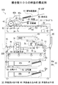
図1は、本発明の実施形態としての画像形成装置を応用した複合機100の構成例を示す断面の概念図である。
この実施形態では編集・閲覧可能なテキスト形式の画像形成プログラムから画像形成条件を解析する解析手段を備え、このテキスト形式により記述された画像形成プログラムから画像形成条件を容易に再生できるようにすると共に、既存のユーザインタフェース以外からも画像形成ジョブを投入できるようにしたものである。
【0018】
図1に示す複合機100は画像形成装置の一例であり、編集・閲覧可能なテキスト形式の画像形成プログラム(以下スクリプトという)に記述された所望の画像形成条件(以下ジョブパラメータという)に基づいて任意の画像形成ジョブを実行する装置である。このスクリプトとは画像形成プログラムの一例であって、ジョブパラメータを設定するためのコマンド群を記述した簡易的なプログラムをいう。つまり、画像形成手順を記述した一連のテキスト(プログラムと同じ意味)である。このスクリプトを作成するためのスクリプト言語を指すこともある。
【0019】
また、ジョブパラメータとは、ユーザが指定したジョブを実行するために必要な画像形成条件又は画像形成条件群をいう。このスクリプトには少なくとも、ユーザが指定したジョブパラメータと、画像情報の格納先を指定する指定情報とが含まれる。
【0020】
図1に示す白黒用のディジタル複合機(コピア;以下単に複合機という)200は画像形成装置の一例であり、画像形成用のスクリプト及び任意の画像データに基づいて画像を形成する装置である。この複合機100は原稿を読み取って相手方に画像データを送信する通信機能、原稿を読み取って所定の用紙に画像を形成するコピー機能、原稿を読み取って相手方に原稿画像を送信するファクシミリ送信(FAX送信)機能、相手方の端末装置から受信した原稿画像を用紙に形成するファクシミリ受信(以下でFAX受信という)機能及び、パーソナルコンピュータ(以下パソコンという)から受信した画像データに基づいて用紙に画像を形成するプリント機能の5つを有している。
【0021】
図1において、複合機100は大きく分けて給紙手段30、自動原稿給紙装置(ADF)40、画像読み取り部50、画像書込み部60及び画像形成手段80等から構成される。給紙トレイ30a、30b・・・は給紙手段30を構成し、給紙トレイ30aには例えば、A4サイズのコピー用紙が横向きにセットされる。給紙トレイ30bには例えば、A3サイズのコピー用紙が横向きにセットされる。
【0022】
図1では給紙トレイ30a、30bが2個の場合を示しているが、これに限られることはなく、図示しないがA4サイズのコピー用紙を縦向きにセットされる給紙トレイや、B5サイズ等のコピー用紙をセットされる給紙トレイが準備されている。
【0023】
これらの用紙Pとして52.3〜63.9kg/m2(1000枚)程度の薄紙や64.0〜81.4kg/m2(1000枚)程度の普通紙や83.0〜130.0kg/m2(1000枚)程度の厚紙や150.0kg/m2(1000枚)程度の超厚紙が用いられる。用紙Pの厚み(紙厚)としては0.05〜0.15mm程度の厚さのものが用いられる。線速度を80〜350mm/sec程度とし、環境条件として温度が5〜35℃程度、湿度が15〜85%程度の設定条件とすることが好ましい。
【0024】
また、自動原稿給紙装置40は原稿載置部41、ローラ42a、ローラ42b、ローラ43、反転ローラ44、反転部45及び排紙皿46を有している。原稿載置部41には例えば、原稿表面を上にした状態で、複数枚の原稿20が載置される。そして、図示しないADF制御部によってローラ42a及びローラ42bが駆動されると、これらのローラ42a及びローラ42bを介して繰り出された原稿20の1枚目がローラ43を介して画像読み取り部50へ搬送される。
【0025】
画像読み取り部50は第1のプラテンガラス51、第2のプラテンガラス52、光源53、ミラー54、55、56、結像光学系57、CCD撮像装置58及び図示しない光学駆動系を有している。画像読み取り部50では光源53から原稿20の画像面に光が照射される。この反射光はミラー54,55,56によって案内され、その反射光が結像光学系57を介してCCD撮像装置58の受光面に原稿20の画像が結像される。これにより、CCD撮像装置58に原稿画像が取り込まれる。
【0026】
また、プラテンガラス51上で、つまり、原稿20の読み取り面を下に向けた状態で、その原稿20が原稿載置部41に載置された場合は、光学駆動系がプラテンガラス51に沿って、画像読み取り部50を走査することで原稿画像がCCD撮像装置58に取り込まれる。
【0027】
なお、自動原稿給紙装置40において、原稿20の両面読取モードの場合は、ローラ43の周囲を原稿20が回るようになる。この場合にはプラテンガラス52下に光源53とミラー54とが固定された状態で、原稿画像が画像読み取り部50によって読み取られる。そして、原稿20の表面が読み取られると、今度は反転ローラ44を介して再度、ローラ43を用いた巻き取り操作が行われ、原稿裏面の画像が画像読み取り部50で読み取られる。このように表面と裏面の画像が読み取られた原稿20は、再度反転ローラ44で反転されて表面を下に向けた状態で、排紙皿46に積載されて行く。
【0028】
一方、用紙Pが積載されている給紙トレイ30a又は30bから、用紙Pが繰り出されて画像形成手段80に給送される。画像形成手段80は画像書込み部60、感光体ドラム71、帯電部72、現像部73、転写部74、分離部75、クリーニング部76、搬送機構77及び定着部78を有している。
【0029】
ここで用紙Pの一方の面のみに画像を形成する片面モードの場合を例にとると、用紙Pは転写部74の入り口付近に設けられた、レジストローラ61で同期が採られた後に感光体ドラム71に、より近接する。この状態で、画像書き込み部60内では、画像情報に応じた所定の強度のレーザ光がレーザダイオードから感光体ドラム71上へ照射される。これにより、感光体ドラム71に原稿20の静電潜像が形成される。この静電潜像は現像部73からのトナーにより現像された後に、感光体ドラム71上にトナー像となって形成される。
【0030】
このトナー像は感光体ドラム71の下部に設けられた転写部74上に搬送された用紙Pに転写される。このとき、用紙Pは感光体ドラム71に吸着される。そして、感光体ドラム71に吸着された用紙Pは分離部75によって感光体ドラム71から分離される。その後、感光体ドラム71から分離された用紙Pは搬送機構77を介して定着部78に送出され、トナー像が熱と圧力とにより定着される。
【0031】
これにより、用紙Pの所定の面(被形成面)に原稿画像が形成される。感光体ドラム71に残留付着したトナーはクリーニング部76により除去され、次の画像形成に対処すべく待機する。この画像形成が完了した用紙Pは、例えば、フィニッシャ部300で出力形態(ソータ機能及びステプラー機能などの操作指示)に対応して、そのまま機外に排出される(片面モード)。
【0032】
この複合機100では用紙反転機構が備えられ、両面モードが設定されると、用紙Pの表裏を反転するようになされる。用紙反転機構はガイド91、反転ローラ92、反転部93、反転搬送路94及び、排紙ローラ95から構成される。この両面モードでは、トナー像が定着された用紙Pが排紙処理に移行されることなく、ガイド91を介して画像形成手段80の下方に搬送され、反転部93に送出される。次に、反転部93に送出された用紙Pは反転ローラ92で、再度上方向に繰り出され、用紙Pをスイッチバックするように、給紙トレイ30a上に設けられた反転搬送路94を通って再度、画像形成手段80に転送される。
【0033】
反転搬送路94では、用紙Pの被形成面(未だ画像形成されていない面)上にして、用紙Pがレジストローラ61を介して画像形成手段80に送出される。画像形成手段80では上述した表面の場合と同様にして、感光体ドラム71に原稿20に係る静電潜像が形成され、この静電潜像が現像部73で現像されるので、感光体ドラム71上に原稿20に係るトナー像が形成される。
【0034】
このトナー像は転写部74によって用紙Pの他方の面に転写される。感光体ドラム71に吸着された用紙Pは分離部75によって感光体ドラム71から分離された後に、搬送機構77を介して定着部78に送出され、トナー像が熱と圧力とにより定着される。上述した原稿20の画像形成が終了した画像形成手段80では、感光体ドラム71に残留付着したトナーがクリーニング部76により除去され、次の画像形成に対処すべく待機する。これにより、原稿20に係る画像を用紙Pの表裏に形成することができる。
【0035】
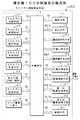
[複合機の制御系の構成例]
図2は複合機100の制御系の構成例を示すブロック図である。図2に示す複合機100は制御手段15を有しており、テキストエディタ等で容易に編集可能なテキスト形式によりジョブパラメータJpを記述するようになされる。テキストエディタとは、パーソナルコンピュータ等で文字のみのテキストファイルを作成・編集するためのアプリケーションソフトウエアをいう。
【0036】
この制御手段15には、ハードウエアによって構成される画像処理手段16、操作手段17、表示手段18、ジョブ登録メモリ19、給紙手段30、第1の画像記憶手段31、第2の画像記憶手段32、情報通信手段33、画像読み取り部50、画像書込み部60及び画像形成手段80と、ソフトウエアによって構成されるスクリプト情報処理手段12とが接続される。
【0037】
画像読み取り部50では任意の原稿上を図示しない光学系を露光走査して画像が読み取られ、原稿読取データD1が取得される。原稿読取データD1は画像処理手段16へ出力される。画像処理手段16では画像読み取り部50から得られた原稿読取データD1を所定の画像圧縮機能等を利用して画像処理するようにされる。この例では、画像処理後の原稿読取データD1を画像データDINという。
【0038】
画像処理後の画像データDINは第1の画像記憶手段(第1の記憶手段)31等に出力され記憶される。第1の画像記憶手段31に記憶された画像データDINは画像形成データDOUTとなって、予め設定されたジョブパラメータJpに基づいて画像書込み部60へ読み出される。画像書込み部60では画像形成データDOUTに基づいて感光体に静電潜像が記録される。
【0039】
画像形成手段80では給紙手段30から繰り出される所定の大きさの用紙に、画像データDINに基づく画像を形成するようになされる。給紙手段30では制御手段15による給紙制御データD5に基づいて給紙制御され、画像形成手段80は濃度制御データD6等に基づいて出力制御される。このような画像形成動作を画像形成ジョブという。
【0040】
この例で制御手段15には入力手段の一例となる操作手段17が接続され、画像形成ジョブに関してユーザにより、ジョブパラメータJpを操作入力するようになされる。ジョブパラメータJpは操作データD2として制御手段15へ入力される。操作手段17には図示しないが液晶表示ディスプレイとタッチパネルを組み合わせた操作パネルが使用される。
【0041】
上述のスクリプト情報処理手段12はスクリプト生成手段21、スクリプト加工手段22、スクリプト記憶手段23、スクリプト送信手段24、スクリプト受信手段25、スクリプト判定手段26及びスクリプト解析手段27から構成される。
【0042】
このスクリプト情報処理手段12にはプログラム作成手段の一例となるスクリプト生成手段21が設けられ、操作手段17により操作入力されたジョブパラメータJpから編集可能なテキスト形式のスクリプトScを作成するようになされる。例えば、スクリプト生成手段21では、スクリプトScにジョブ投入時刻を記述したり、画像形成ジョブに関して複数のスクリプトScを1つのファイルに連結するようになされる。
【0043】
このようにすると、スクリプトScに変換されたジョブパラメータJpを複数記憶することができ、ユーザが設定したジョブパラメータJpがエディタ等で容易に編集可能なテキスト形式のスクリプトScで記述されるため、投入ジョブのジョブパラメータJpを容易に見ることができる。ファイルとは文字情報を記述したデータをいう。複数のスクリプトScを連結することにより、複数の画像形成ジョブを順次実行することが可能となる。
【0044】
また、スクリプトを連結することにより、後から必要であれば、別々の予約ジョブをバッチ処理など連続した処理とすることができる。バッチ処理とは、一定期間若しくは一定量のデータを集め、まとめて、一括処理を行う処理方式をいう。または、複数の手順から成る処理おいて、予め一連の手順を登録しておき、自動的に連続処理を行う処理方式をいう。
【0045】
また、スクリプト情報処理手段12にはスクリプト生成手段21の他に、プログラム加工手段の一例となるスクリプト加工手段22が設けられ、画像形成ジョブに関してスクリプト生成手段21により作成されたスクリプトSc又は、スクリプト生成手段21以外の他の情報処理機器から受信入力されたスクリプトScを独立したジョブ毎に分割するようになされる。この独立したジョブとは、例えば、「コピージョブ」であれば、独立したジョブとは「原稿読込みジョブ」や「画像形成ジョブ」をいう。
【0046】
このようにすると、ユーザが登録した複数の一連のジョブであっても、独立したジョブ毎にジョブパラメータJpを分割することができるので、分割された未実行の残ジョブについては、対応するスクリプトScをユーザに送信することができる。そのため、その実行タイミングを再度ユーザにゆだねることができるため、機密性の高い文書のコピーなどはプリントアウトが自動的に起動することを防げ、かつ、ジョブの登録リストからも消えるため、見た目はジョブが登録されていないようにすることができる。
【0047】
また、スクリプト情報処理手段12にはスクリプト記憶手段23が設けられ、スクリプト生成手段21により生成された画像形成ジョブに関するスクリプトSc又は、スクリプト加工手段22により加工された画像形成ジョブに関するスクリプトScが記憶される。
【0048】
スクリプト情報処理手段12には送信手段の一例となるスクリプト送信手段24が設けられ、スクリプト生成手段21により作成されたスクリプトScをLCDパネル等のユーザインタフェース、又は、他の複合機等に送信するようになされる。例えば、スクリプト送信手段24はスクリプト生成手段21により作成されたスクリプトScを管理者宛、又は管理手段に送信するようになされる。
【0049】
また、制御手段15には表示手段18が接続され、操作手段17により操作入力されたジョブを登録リストに表示するようになされる。表示手段18には例えば、液晶表示ディスプレイ(LCDパネル)が使用される。この例では、ユーザインタフェース又は、他の複合機100へ送信したスクリプトScに関しては、制御手段15によって表示手段18の登録リストから当該ジョブの表示を消去するように制御される。登録リストは表示データD3によって表示される。
【0050】
この制御手段15ではスクリプト生成手段21によって連結されたスクリプトScを受信してそれぞれのジョブを順次実行する。スクリプト情報処理手段12には受信手段の一例となるスクリプト受信手段25が設けられ、画像形成ジョブに関してスクリプト生成手段21以外の他の情報処理機器からスクリプトScを受信するようになされる。
【0051】
スクリプト情報処理手段12にはスクリプト受信手段25の他にプログラム判別手段の一例となるスクリプト判定手段26が設けられ、他の情報処理機器から受信したデータがスクリプトScであるか否かを判別するようになされる。もちろん、これに限られることはなく、操作手段17により操作入力されたジョブか、又は、操作手段17による操作入力以外の他の情報処理機器から受信入力されたジョブかをスクリプト判定手段26によって判別するようにしてもよい。
【0052】
この例では、他の情報処理機器から受信入力されたジョブがスクリプト判定手段26によって検出された場合は、制御手段15によって、当該情報処理機器から受信入力したジョブに対応するスクリプトScの再度送信を禁止するようになされる。このようにすると、他人が自分のスクリプトScを勝手に転送し、別の機器でプリントすることを防げる。
【0053】
また、制御手段15ではスクリプト判定手段26で判別されたスクリプトScの中で解析できない記述があるか否かを検出するようになされる。例えば、制御手段15は、スクリプト判定手段26で情報処理機器から受信したデータがスクリプトScであると判別された場合であって、スクリプトScの中で解析できない記述がある場合は、解析不可を示す旨の制御情報を当該スクリプトScの送信元に送信するようになされる。
【0054】
スクリプト情報処理手段12には解析手段の一例となるスクリプト解析手段27が設けられ、スクリプト判定手段26によって判定されたスクリプトScを入力して当該スクリプトScからジョブパラメータJpを解析するようになされる。もちろん、スクリプト生成手段21により作成されたスクリプトScからジョブパラメータJpを解析するようにしてもよい。
【0055】
この例で制御手段15は、スクリプトScの中に当該ジョブパラメータJpで必要な記述が含まれるかを検出し、この記述が無い場合は、不足する情報について当該複合機100が有するデフォルト値を設定するように制御する。画像形成制御を円滑にするためである。この制御手段15にはジョブ登録メモリ19が接続され、スクリプト解析手段27によって解析されたジョブパラメータJpに基づく画像形成ジョブが登録(記録)される。画像形成ジョブは例えば、ジョブ登録データD4として記憶される。
【0056】
この制御手段15には第1の記憶手段の一例となる第1の画像記憶手段31が接続され、スクリプト生成手段21により作成されたスクリプトScを原稿読み取り部50から得られた画像データDINと共に保存するようになされる。上述した画像形成手段80では、ジョブ登録メモリ19から読み出された画像形成ジョブ、つまり、スクリプト解析手段27により解析されたジョブパラメータJpを設定すると共に、第1の画像記憶手段31から読み出された画像データDINに基づいて画像を形成するようになされる。
【0057】
上述した操作手段17は入力手段の他に選択手段を構成し、スクリプト記憶手段23に格納されたスクリプトSc及び画像データDINに関してスクリプトScのみを削除して関連する画像データDINを残す、又は、当該スクリプトSc及び画像データDINの両方を削除するかを選択するように操作される。このようにすると、前者であれば、スクリプトScのみを削除し、後者であれば、スクリプトSc及び画像データDINの両方を削除する。前者の場合は、再度、スクリプトScを受信することにより、画像データDINの操作(ジョブ実行)が可能となる。
【0058】
制御手段15は監視手段及びプログラム切出し手段を構成し、画像形成ジョブに関して現在実行中のジョブの終了を監視し、ここで監視されるジョブのスクリプトScを切り出すようになされる。この例では、制御手段15により切り出されたスクリプトScに対応したジョブと共に、当該ジョブに関連する画像データDINが、上述した第1の画像記憶手段31に記録するようになされる。
【0059】
また、制御手段15によって前ジョブが実行中で待ちジョブが検出された場合に、当該制御手段15により切り出された待ちジョブに対応するスクリプトScをユーザインタフェース又は、他の複合機等に送信するようになされる。この制御手段15には第2の記憶手段の一例となる第2の画像記憶手段32が接続され、制御手段15によって切出されたスクリプトScが記憶されると共に、このスクリプトScの読み出しがパスワードで保護される。スクリプトScには、予め暗号化アルゴリズムにより暗号化された当該記憶手段32へのアクセスに関するパスワード、又は、暗号化されていない記憶手段へのアクセスに関するパスワードが記述され、データ受信時には、当該パスワードを解析して第2の画像記憶手段32にアクセスするようになされる。
【0060】
この制御手段15には第2の画像記憶手段32の他に、通信手段の一例となる情報通信手段33が接続され、スクリプトScを記憶すると共に、スクリプトScを送信する相手であるユーザインタフェース又は、他の複合機100が設定されていない場合は、情報通信手段33に記憶されたスクリプトScを実行するようになされる。
【0061】
この例で情報通信手段33にはパスワードを要求する手段が備えられ、スクリプトScを実行する場合に、当該パスワードを解析して情報通信手段33にアクセスするようになされる。また、情報通信手段33に記憶されたスクリプトScを他のユーザインタフェース又は、他の複合機に送信し、改めてユーザインタフェース又は、他の複合機の設定を変更するようになされる。このような機能の他に、情報通信手段33は原稿読取データD1をFAXデータD7として送信したり、相手方の端末装置から受信したFAXデータD7を受信したりする機能を有している。
【0062】
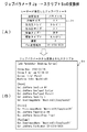
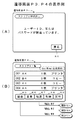
続いて、ジョブパラメータJpからスクリプトScへ変換する例について説明をする。図3A及びBはジョブパラメータJp→スクリプトScの変換例を示すイメージ図である。
【0063】
図3Aに示すジョブパラメータJpは、ユーザが操作手段17を使用して指定した例である。ジョブパラメータJpは各種の設定項目とこれに対応したパラメータから構成される。この例では設定項目「原稿サイズ」に対してパラメータ「A4」が設定され、設定項目「出力先トレイ」に対してパラメータ「トレイ1」が設定される。同様にして、設定項目「出力紙サイズ」に対してパラメータ「A4」が設定される。更に、設定項目「原稿タイプ1」に対してパラメータ「文字」が設定され、設定項目「原稿タイプ2」に対してパラメータ「えんぴつ」が設定される。設定項目「濃度」に対してパラメータ「3」が設定され、設定項目「Fax送信宛先」に対してパラメータ「03−1234−5678」が設定される。
【0064】
このような図3Aに示したジョブパラメータJpから図3Bに示すようなスクリプトScが生成される。図3Bに示すスクリプトScはスクリプト生成手段21及びスクリプト加工手段22によって作成されてファイルに記述される。
【0065】
この例で、図1に示したスクリプト生成手段21は操作手段17により操作入力されたジョブパラメータJpから編集可能なテキスト形式のスクリプトScを作成する。例えば、図3Bに示すように、[Job Parameter Setting Script]等の表題がテキスト形式のスクリプトScで記述され、その表題の下方に「Throw Day:2002/04/05」等のジョブ投入日がテキスト形式のスクリプトScで記述される。
【0066】
また、日付の下方には「Throw Time:am 10:24:32」等のジョブ投入時刻がテキスト形式のスクリプトScで記述され、その投入時刻の下方に「Script Info:Panel」等の操作手段17がテキスト形式のスクリプトScで記述され、その操作手段17の下方に「Machin Info:Machin 01」等の機械装置名がテキスト形式のスクリプトScで記述される。このようにすると、複数のスクリプトを時間情報と関連付けて、1つのファイルに連結することができる。しかも、連結されたスクリプトを受信した際には、ユーザが投入したジョブのジョブパラメータJp及びタイミングを再現することができる。
【0067】
更に、[Job Parameter Setting Script]等の表題の次には原稿読取設定欄が設けられ、[Scan]等がテキスト形式のスクリプトScで記述され、その原稿読取設定欄には原稿サイズA4に関して「Set JobPara DocSize A4」等がテキスト形式のスクリプトScで記述される。更に、原稿タイプ1に関して「Set JobPara DocType1 Letter」等がテキスト形式のスクリプトScで記述され、原稿タイプ2に関して「Set JobPara DocType2 Pencil」等がテキスト形式のスクリプトScで記述される。
【0068】
また、画像形成時の濃度に関して「Set JobPara Densty 3」等がテキスト形式のスクリプトScで記述される。更に原稿読取装置に関して「Set ScanImageName ’’Machin01/CopyScan01」等がテキスト形式のスクリプトScで記述される。
【0069】
更に、原稿読取設定欄の下方には印刷設定欄が設けられ、[Print]等がテキスト形式のスクリプトScで記述され、その印刷設定欄にプリンタに関して「Set PrintImageName ’’Machin01/CopyScan01」等がテキスト形式のスクリプトScで記述される。また、出力紙サイズA4に関しては「Set JobPara PaperSize A4」等がテキスト形式のスクリプトScで記述され、出力先トレイ「1」に関しては「Set JobPara OutputTray Tray1」等がテキスト形式のスクリプトScで記述される。
【0070】
また、印刷設定欄の下方にはFax送信宛先欄が設けられ、[FaxComm]等がテキスト形式のスクリプトScで記述され、そのFax送信宛先欄にはファクシミリ装置に関して「Set SendImageName ’’Machin01/CopyScan01」等がテキスト形式のスクリプトScで記述される。Fax送信宛先に関しては「Set JobPara FaxNummber 03−1234−5678」等がテキスト形式のスクリプトScで記述される。
【0071】
このようにして、操作手段17により操作入力されたジョブパラメータJpをスクリプト生成手段21及びスクリプト加工手段22により4つのスクリプトScに変換することができる。この画像形成ジョブに関して4つのスクリプトSc、[Job Parameter Setting Script]、[Scan]、[Print]及び、[FaxComm]を1つのファイルに連結するようになされる。このような4つのスクリプトScを連結することにより、複数のJOBを順次実行することが可能となる。
【0072】
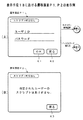
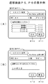
図4〜図7は表示手段18における遷移画面P1〜P7の表示例を示すイメージ図である。図4A及びBは遷移画面P1及びP2の表示例を示すイメージ図である。図4Aに示す遷移画面P1は、例えば、図示しない初期画面でスクリプトモードを選択することで表示されるものである。この表示例によれば、図1に示した表示手段18の表示画面には「スクリプト呼出し」の項目欄や、「OK」のタッチキーK1、「戻る」のタッチキーK2が設けられる。この表示画面の中央にはユーザーIDの入力欄や、パスワード入力欄が設けられる。
【0073】
この遷移画面P1でユーザーIDを入力したり、パスワードを入力するようになされる。ユーザIDや、パスワード等は図示しない「0」〜「9」の数字キーや、「*」や「#」等の記号キーを使用して入力される。これらの入力操作が完了したら、「OK」のタッチキーK1を押下する。
【0074】
なお、遷移画面P1でスクリプト未登録の場合は、図4Bに示すような遷移画面P2へ表示が切り替わる。この遷移画面P2には「指定されたユーザのスクリプトはありません。」等のメッセージが表示される。この画面が表示されたら、ユーザーは「戻る」のタッチキーK3を押下して遷移画面P2から遷移画面P1へ戻るようになされる。最初からパラメータを入力してスクリプトScを登録させるためである。
【0075】
また、ID/パスワード等の誤入力の場合は、図5Aに示すような遷移画面P3に表示が切り替わるようになされる。この遷移画面P3には「ユーザーIDまたはパスワードが間違っています。」等のメッセージが表示される。この画面が表示されたら、ユーザーは「戻る」のタッチキーK2を押下して遷移画面P2から遷移画面P1へ戻るようになされる。もう一度、ユーザIDや、パスワード等を入力するためである。
【0076】
上述した図4Aの遷移画面P1で「OK」のタッチキーK1を押下すると、図5Bに示す遷移画面P4に表示が切り替わるようになされる。この遷移画面P4には、「スクリプト一覧」の項目欄、「User Name:山田太郎」の名前欄が表示される。この表示の下方には、画像形成ジョブ表示欄が設けられ、この画像形成ジョブとして、例えば、シリアルNo「001」に「A4 1枚 プリンタ」が表示され、その下方にはシリアルNo「002」に「B4 3枚 コピー」が表示され、その下方にはシリアルNo「003」に「A4 6枚 コピー」が表示され、その下方にはシリアルNo「004」に「A4 1枚 プリンタ」が表示されている。
【0077】
更に、画像形成ジョブ表示欄の下方には、「結合」、「変更」、「転送」、「削除」及び「実行」のタッチキーK5,K6,K7,K8,K9が各々表示される。各々のスクリプトScを登録するためである。この例で「転送」のタッチキーK7を選択して押下すると、遷移画面P4から図6Aに示す遷移画面P5に表示が切り替わるようになされる。スクリプトScにおける「転送」を登録するためである。
【0078】
この遷移画面P5には、「スクリプト転送」の項目欄、「User Name:山田太郎」の名前欄が表示される。この表示の下方には、画像形成ジョブ表示欄が設けられ、この画像形成ジョブとして、例えば、シリアルNo「001」に「A4 1枚 プリンタ」が表示される。その下方には「転送先を選択してください」のメッセージ欄が表示される。このメッセージ欄の下方には、「複合機A」、「複合機B」、「プリンタC」及び「プリンタD」等のタッチキーK12,K13,K14,K15が各々表示される。ユーザは複合機やプリンタ等の転送先を選択して「OK」のタッチキーK10を押下する。これにより、スクリプトScにおける「転送」を登録することができる。
【0079】
また、図5Bで「変更」のタッチキーK6を選択して押下すると、遷移画面P4から図6Bに示す遷移画面P6に表示が切り替わるようになされる。スクリプトScにおけるユーザーIDの「変更」を登録するためである。この遷移画面P6には、「スクリプト変更」の項目欄、「User Name:山田太郎」の名前欄が表示される。この表示の下方には、画像形成ジョブ表示欄が設けられ、この画像形成ジョブとして、例えば、シリアルNo「002」に「B4 3枚 コピー」が表示される。その下方には「変更するユーザ名を入力してください」のメッセージ欄が表示される。このメッセージ欄の下方にはユーザーIDの入力欄が表示される。ここで変更に係るユーザーIDを入力して「OK」のタッチキーK13を押下する。これにより、スクリプトScにおけるユーザーIDの「変更」を登録することができる。
【0080】
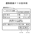
更に、図5Bで「結合」のタッチキーK5を選択して押下すると、遷移画面P4から図7に示す遷移画面P7に表示が切り替わるようになされる。スクリプトScの「結合」を登録するためである。
【0081】
この遷移画面P7には、「スクリプト連結」の項目欄、「User Name:山田太郎」の名前欄が表示される。この表示の下方には、画像形成ジョブ表示欄が設けられ、この画像形成ジョブとして、例えば、シリアルNo「002」の「B4 3枚 コピー」が表示される。その下方にはシリアルNo「004」の「A4 1枚 プリンタ」が表示される。この画像形成ジョブ表示欄の中央には「上記2個のスクリプトを結合し、以下のスクリプトを作成します。」等のメッセージが表示される。このメッセージの下方にはシリアルNo「006」として「結合スクリプト002/004 結合」が表示される。この結合を確認(同意)したユーザーは「実行」のタッチキーK9を押下する。これにより、シリアルNo「002」のスクリプトScと、シリアルNo「004」のスクリプトScとの結合を登録することができる。
【0082】
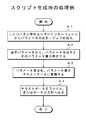
続いて、本発明に係る画像形成方法について複合機100の動作例を説明する。図8は複合機100におけるスクリプト生成時の処理例を示すフローチャートである。図9は複合機100におけるスクリプト解析時の処理例を示すフローチャートである。
【0083】
この実施形態では、画像データDINに基づいて任意の画像を形成する場合を前提とする。画像形成ジョブの投入時に、任意の画像に関してジョブパラメータJpを入力する。ここで入力されたジョブパラメータJpを編集可能なテキスト形式のスクリプトScに変換する。画像形成時には、スクリプトScからジョブパラメータJpを解析する。ここで解析されたジョブパラメータJpを設定すると共に画像データDINに基づいて画像を形成する場合を例に採る。この例ではスクリプト生成処理及びスクリプト解析処理の2つに分けて説明する。
【0084】
[スクリプト生成処理]
この処理例では、テキストエディタ等でユーザが容易に編集可能なように、ジョブ投入時に、ジョブパラメータJpをスクリプトScに変換する。つまり、ユーザが投入したジョブパラメータJpを編集可能なテキスト形式のスクリプトScにする。
【0085】
これらを処理条件にして、図8に示すフローチャートのステップA1でLCDパネル等のユーザインタフェースからパラメータの設定及びジョブを投入する。このとき、ユーザは操作手段17を使用して画像形成ジョブに関し、図3Aに示したようなジョブパラメータJpを操作入力する。ジョブパラメータJpは操作データD2として制御手段15へ入力される。
【0086】
そして、ステップA2で制御手段15又はスクリプト解析手段27は設定パラメータから、パラメータ項目名とそのパラメータ値を解析する。その後、ステップA3に移行して、パラメータ項目名、パラメータ値をテキストデータに変換する。このとき、スクリプト生成手段21では、操作手段17により操作入力されたジョブパラメータJpから編集可能なテキスト形式のスクリプトScを作成するようになされる。例えば、スクリプト生成手段21では、図3Bに示したように、スクリプトScにジョブ投入時刻を記述したり、画像形成ジョブに関して複数のスクリプトScを1つのファイルに連結するようになされる。複数のスクリプトScを連結することにより、複数の画像形成ジョブを順次実行することができる。
【0087】
また、スクリプト加工手段22では、画像形成ジョブに関してスクリプト生成手段21により作成されたスクリプトSc又は、スクリプト生成手段21以外の他の情報処理機器から受信入力されたスクリプトScを独立したジョブ毎に分割するようになされる。このようにすると、ユーザが登録した複数の一連のジョブであっても、独立したジョブ毎にジョブパラメータJpを分割することができるので、分割された未実行の残ジョブについては、対応するスクリプトScをユーザに送信することができる。そのため、その実行タイミングを再度ユーザにゆだねることができる。機密性の高い文書のコピーなどはプリントアウトが自動的に起動することが防げ、かつ、登録ジョブリストからも消えるため、見た目はジョブが登録されていないようにできる。
【0088】
そして、ステップA4でテキスト形式のスクリプト(テキストデータ)Scをスクリプト記憶手段23またはスクリプト送信手段24へ出力する。このとき、スクリプト生成手段21により生成された画像形成ジョブに関するスクリプトSc又は、スクリプト加工手段22により加工された画像形成ジョブに関するスクリプトSc、つまり、テキストデータはスクリプト記憶手段23に記憶(ファイル)される。また、表示手段18にスクリプトを送信する場合はスクリプト送信手段24を通じて出力される。表示手段18ではジョブの登録リストが表示される。この登録リストは表示データD3によって表示される。
【0089】
他の複合機等にスクリプトを送信する場合は制御手段15の制御を受けてスクリプト送信手段24及び情報通信手段33を通じて外部へ出力される。例えば、スクリプト送信手段24はスクリプト生成手段21により作成されたスクリプトScを管理者宛、又は管理手段に送信するようになされる。この例では、ユーザインタフェース又は、他の複合機100へ送信したスクリプトScに関しては、制御手段15によって表示手段18の登録リストから当該ジョブの表示を消去するように制御される。
【0090】
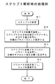
[スクリプト解析例]
この処理例でスクリプト情報処理手段12上のジョブ実行部では、再度スクリプトScを解析し、ジョブパラメータJpを設定して画像形成ジョブを実行するようになされる。従って、未実行ジョブについてのみ再度ユーザに送信し、再投入のタイミングを促すことができる。
【0091】
これらを処理条件にして、図9に示すフローチャートのステップB1でスクリプトScを受信する。このとき、制御手段15では例えば、スクリプト生成手段21によって連結されたスクリプトScを受信してそれぞれのジョブを順次実行する。もちろん、スクリプト受信手段25を通じて画像形成ジョブに関してスクリプト生成手段21以外の他の情報処理機器からスクリプトScを受信するようにしてもよい。
【0092】
このとき、スクリプト判定手段26では、他の情報処理機器から受信したデータがスクリプトScであるか否かを判別するようになされる。もちろん、これに限られることはなく、操作手段17により操作入力されたジョブか、又は、操作手段17による操作入力以外の他の情報処理機器から受信入力されたジョブかをスクリプト判定手段26によって判別するようにしてもよい。
【0093】
この例では、他の情報処理機器から受信入力されたジョブがスクリプト判定手段26によって検出された場合は、制御手段15によって、当該情報処理機器から受信入力したジョブに対応するスクリプトScの再度送信を禁止するようになされる。このようにすると、他人が自分のスクリプトScを勝手に転送し、別の機器でプリントすることを防げる。
【0094】
また、制御手段15ではスクリプト判定手段26で判別されたスクリプトScの中で解析できない記述があるか否かを検出するようになされる。例えば、制御手段15は、スクリプト判定手段26で情報処理機器から受信したデータがスクリプトScであると判別された場合であって、スクリプトScの中で解析できない記述がある場合は、解析不可を示す旨の制御情報を当該スクリプトScの送信元に送信するようになされる。
【0095】
そして、ステップB2でスクリプトScの記述を解析する。このとき、スクリプト解析手段27では、スクリプト判定手段26によって判定されたスクリプトScを入力して当該スクリプトScからジョブパラメータJpを解析するようになされる。もちろん、スクリプト生成手段21により作成されたスクリプトScからジョブパラメータJpを解析するようにしてもよい。そして、スクリプトScから自機の設定パラメータに対応する値を取得し、自機のパラメータを設定する。
【0096】
その後、ステップB3でスクリプトScに記述されていないパラメータを判定する。このとき、制御手段15ではスクリプトScの中に当該ジョブパラメータJpで必要な記述が含まれるかを検出する。この記述が無い場合は、不足する情報について当該複合機100が有するデフォルト値を自機に設定するように制御する。これにより、自機のデフォルト値を自機に設定することができ、画像形成制御を円滑にすることができる。
【0097】
そして、ステップB4でパラメータの設定を完了し、画像形成ジョブを登録する。このとき、ジョブ登録メモリ19にはスクリプト解析手段27によって解析されたジョブパラメータJpに基づく画像形成ジョブが、例えば、ジョブ登録データD4として登録(記録)される。
【0098】
この画像形成ジョブを実際に実行する場合は、ジョブ登録データD4に基づいてジョブ原稿読み取り部50によって原稿が読取られ、画像データDINがスクリプトScと共に第1の画像記憶手段31に記憶され保存される。第1の画像記憶手段31に記憶された画像データDINは画像形成データDOUTとなって、予め設定されたジョブパラメータJpに基づいて画像書込み部60へ読み出される。画像書込み部60では画像形成データDOUTに基づいて感光体に静電潜像が記録される。
【0099】
画像形成手段80では給紙手段30から繰り出される所定の大きさの用紙に、画像データDINに基づく画像を形成するようになされる。給紙手段30では制御手段15による給紙制御データD5に基づいて給紙制御され、画像形成手段80は濃度制御データD6等に基づいて出力制御される。
【0100】
このように、本発明に係る実施形態としての複合機100及び画像形成方法によれば、所望のジョブパラメータJpに基づいて任意の画像形成ジョブを実行する場合に、スクリプト解析手段27には編集・閲覧可能なテキスト形式により記述されたスクリプトScが入力され、このスクリプトScからジョブパラメータJpを解析するようになされる。
【0101】
従って、テキスト形式により記述されたスクリプトScからジョブパラメータJpを容易に再生できるので、画像形成手段80ではスクリプト解析手段27により解析されたジョブパラメータJpを設定すると共に画像データDINに基づいて画像を形成できるようになる。
【0102】
これにより、既存の入力手段等のユーザインタフェース以外にも、スクリプトScを生成可能なパーソナルコンピュータや、携帯電話機などのネットワーク上に接続された非専用電子機器からも画像形成ジョブを投入することが可能となり、事実上無制限に画像形成機能を拡張できるようになる。
【0103】
しかも、テキストエディタで閲覧・編集できるデータを基本的なインタフェースとすることにより、専用のユーザインタフェース等の入力手段を必要としなくなる。
【0104】
なお、この実施形態では白黒用の複合機200の場合について説明したが、これに限られることはなく、カラー用の複合機や複写機の場合についても同様な効果が得られる。
【0105】
【発明の効果】
以上説明したように、本発明に係る画像形成装置によれば、編集・閲覧可能なテキスト形式の画像形成プログラムを入力して当該画像形成プログラムから画像形成条件を解析する解析手段を備えるものである。
【0106】
この構成によって、テキスト形式により記述された画像形成プログラムから画像形成条件を容易に再生することができる。従って、既存のユーザインタフェース以外にも、画像形成プログラムを生成可能なパーソナルコンピュータや、携帯電話機などのネットワーク上に接続された非専用電子機器からも画像形成ジョブを投入することが可能となり、事実上無制限に画像形成機能を拡張できるようになる。
【0107】
本発明に係る画像形成方法によれば、画像形成ジョブの投入時に、任意の画像に関して画像形成条件を入力し、ここで入力された画像形成条件を編集可能なテキスト形式の画像形成プログラムに変換し、画像形成時には、画像形成プログラムから画像形成条件を解析し、ここで解析された画像形成条件を設定すると共に画像情報に基づいて画像を形成するようになされる。
【0108】
この構成によって、既存のユーザインタフェース以外にも、画像形成プログラムを生成可能なパーソナルコンピュータや、携帯電話機などのネットワーク上に接続された非専用電子機器からも画像形成ジョブを投入することが可能となる。
【0109】
この発明は、複写機能、ファクシミリ機能及びプリンタ機能を備えたディジタル複合機や複写機等に適用して極めて好適である。
【図面の簡単な説明】
【図1】本発明の実施形態としての画像形成装置を応用した複合機100の断面の構成例を示す概念図である。
【図2】複合機100の制御系の構成例を示すブロック図である。
【図3】A及びBはジョブパラメータJp→スクリプトScの変換例を示すイメージ図である。
【図4】A及びBは表示手段18における遷移画面P1及びP2の表示例を示すイメージ図である。
【図5】A及びBは表示手段18における遷移画面P3及びP4の表示例を示すイメージ図である。
【図6】A及びBは表示手段18における遷移画面P5及びP6の表示例を示すイメージ図である。
【図7】表示手段18における遷移画面P7の表示例を示すイメージ図である。
【図8】複合機100におけるスクリプト生成時の処理例を示すフローチャートである。
【図9】複合機100におけるスクリプト解析時の処理例を示すフローチャートである。
【符号の説明】
12 スクリプト情報処理手段
15 制御手段
16 画像処理手段
17 操作手段
18 表示手段
19 ジョブ登録メモリ
21 スクリプト生成手段(プログラム作成手段)
22 スクリプト加工手段(プログラム加工手段)
23 スクリプト記憶手段(プログラム記憶手段)
24 スクリプト送信手段(送信手段)
25 スクリプト受信手段(受信手段)
26 スクリプト判定手段(プログラム判別手段)
27 スクリプト解析手段(解析手段)
31 第1の画像記憶手段(第1の記憶手段)
32 第2の画像記憶手段(第2の記憶手段)
50 画像読み取り部
60 画像書込み部
80 画像形成手段
100 複合機(画像形成装置)[0001]
TECHNICAL FIELD OF THE INVENTION
BACKGROUND OF THE
[0002]
[Prior art]
2. Description of the Related Art In recent years, digital copiers that form an image based on image data obtained from a document image have been used. In a copying machine, image information of a document is read by a scanner or the like, and the image information of the document is temporarily stored in an image memory. The image information stored in the image memory is subjected to image processing such as reduction, enlargement, and rotation of the image in response to a user request. Here, an image based on the image data subjected to the image processing is formed on a predetermined sheet by an image forming means (printer). As a result, the original image can be copied.
[0003]
[0004]
[0005]
[Patent Document 1]
JP-A-11-346288
[Patent Document 2]
JP-A-6-124012
[0006]
[Problems to be solved by the invention]
By the way, according to the conventional type image forming apparatus, setting operation of parameters and the like and its operation are performed, and an image forming job is executed based on a script (hereinafter also referred to as an image forming program) read from a script table. At this time, a parameter is acquired, and a job is executed based on the parameter. Therefore, there are the following problems.
[0007]
{Circle around (1)} When a copy job is reserved for the image forming apparatus, for example, if there are a large number of print jobs waiting to be output, if the previously reserved job is not completed, the copy, print, etc. Often does not start.
[0008]
{Circle around (2)} When the previously reserved job ends, the job reserved by the user is automatically started. Therefore, in the case of a highly confidential document, even if a long waiting time is required regardless of the fact that the original has been read, the reading is deleted once and the original is re-executed when all the jobs are completed. Often you have to re-read the.
[0009]
{Circle around (3)} Further, if the parameters that were not necessary at the time of reading the original document but were required for printing (hereinafter also referred to as image forming conditions) were to be changed, the printing was not started. Regardless, the contents cannot be changed in many cases.
[0010]
Accordingly, the present invention has been made to solve the above-described problem, and enables an image forming condition to be easily reproduced from an image forming program for an arbitrary image forming, and also allows an image forming job to be input from other than the existing user interface. It is an object of the present invention to provide an image forming apparatus and an image forming method that can be used.
[0011]
[Means for Solving the Problems]
In order to solve the above problems, an image forming apparatus according to the present invention is an apparatus that executes an arbitrary image forming job based on desired image forming conditions described in an image forming program in a text format that can be edited and viewed. Analyzing means for inputting an image forming program and analyzing image forming conditions from the image forming program; and image forming means for setting image forming conditions analyzed by the analyzing means and forming an image based on image information. Means.
[0012]
According to the image forming apparatus of the present invention, when an arbitrary image forming job is executed based on desired image forming conditions, an image forming program described in a text format that can be edited and viewed is input to the analysis unit. Is done. For example, the image forming conditions are input by operating the input unit for the image forming job. An image forming program in a text format that can be edited from the image forming conditions input and operated by the input means is created by the program creating means. The image forming program created by the program creating unit is stored in the first storage unit together with the image information. The analyzing means analyzes the image forming conditions from the image forming program read from the first storage means.
[0013]
Therefore, since the image forming conditions can be easily reproduced from the image forming program described in the text format, the image forming means can set the image forming conditions analyzed by the analyzing means and form an image based on the image information. Become. Thus, in addition to a user interface such as an existing input unit, an image forming job can be input from a personal computer capable of generating an image forming program or a non-dedicated electronic device such as a mobile phone connected to a network. This allows for virtually unlimited expansion of image forming functions.
[0014]
An image forming method according to the present invention is a method for forming an arbitrary image based on image information. When an image forming job is submitted, an image forming condition is input for an arbitrary image, and the image forming condition input here is input. The conditions are converted into an editable text format image forming program, and at the time of image formation, the image forming conditions are analyzed from the image forming program, and the analyzed image forming conditions are set and an image is formed based on the image information. It is characterized by doing.
[0015]
According to the image forming method of the present invention, when an arbitrary image forming job is executed based on a desired image forming condition, the image forming condition can be easily reproduced from an image forming program described in a text format. The image forming means sets the image forming conditions analyzed by the analyzing means and can form an image based on the image information.
[0016]
Therefore, in addition to the existing user interface, an image forming job can be input from a personal computer capable of generating an image forming program or a non-dedicated electronic device connected to a network such as a mobile phone. The image forming function can be extended without limitation.
[0017]
BEST MODE FOR CARRYING OUT THE INVENTION
Hereinafter, an image forming apparatus and an image forming method according to an embodiment of the present invention will be described with reference to the drawings.
FIG. 1 is a conceptual cross-sectional view showing a configuration example of a multifunction peripheral 100 to which an image forming apparatus as an embodiment of the present invention is applied.
In this embodiment, an analysis unit is provided for analyzing image forming conditions from a text-format image forming program that can be edited and viewed, so that the image forming conditions can be easily reproduced from the image forming program described in the text format. The image forming job can be input from other than the existing user interface.
[0018]
The multifunction peripheral 100 shown in FIG. 1 is an example of an image forming apparatus, and is based on desired image forming conditions (hereinafter, referred to as job parameters) described in an image forming program (hereinafter, referred to as a script) in a text format that can be edited and viewed. The device executes an arbitrary image forming job. The script is an example of an image forming program, and is a simple program that describes a command group for setting job parameters. That is, it is a series of texts (same meaning as a program) describing the image forming procedure. It may also refer to the scripting language used to create this script.
[0019]
The job parameter refers to an image forming condition or a group of image forming conditions necessary to execute a job specified by a user. This script includes at least job parameters specified by the user and specification information for specifying a storage destination of the image information.
[0020]
A black-and-white digital multifunction peripheral (copier; hereinafter, simply referred to as a multifunction peripheral) 200 shown in FIG. 1 is an example of an image forming apparatus, and is an apparatus that forms an image based on an image forming script and arbitrary image data. The multifunction peripheral 100 has a communication function of reading an original and transmitting image data to the other party, a copy function of reading the original and forming an image on a predetermined sheet, and a facsimile transmission (FAX transmission) of reading the original and transmitting the original image to the other party. ) Function, facsimile reception (hereinafter referred to as FAX reception) function of forming an original image received from a terminal device of the other party on paper, and image formation on paper based on image data received from a personal computer (hereinafter referred to as personal computer). It has five print functions.
[0021]
In FIG. 1, the multifunction peripheral 100 roughly includes a
[0022]
FIG. 1 shows a case in which the number of the
[0023]
52.3-63.9 kg / m as these papers P 2 (1000 sheets) of thin paper or 64.0-81.4 kg / m 2 (1000 sheets) of plain paper or 83.0 to 130.0 kg / m 2 (1000 sheets) or 150.0kg / m 2 (Thousands) super thick paper is used. The thickness (paper thickness) of the paper P is about 0.05 to 0.15 mm. It is preferable to set the linear velocity to about 80 to 350 mm / sec, and to set the environmental conditions such that the temperature is about 5 to 35 ° C. and the humidity is about 15 to 85%.
[0024]
Further, the
[0025]
The
[0026]
When the original 20 is placed on the original placing portion 41 on the platen glass 51, that is, with the reading surface of the original 20 facing downward, the optical drive system moves along the platen glass 51. By scanning the
[0027]
In the
[0028]
On the other hand, the paper P is fed out from the
[0029]
Here, in the case of a single-side mode in which an image is formed only on one side of the sheet P, for example, the sheet P is provided with a photoconductor after synchronization with a
[0030]
This toner image is transferred onto the sheet P conveyed on a
[0031]
As a result, a document image is formed on a predetermined surface (formation surface) of the sheet P. The toner remaining on the
[0032]
The multifunction peripheral 100 is provided with a sheet reversing mechanism, and when the duplex mode is set, the sheet P is reversed. The sheet reversing mechanism includes a
[0033]
In the reverse conveyance path 94, the sheet P is sent to the
[0034]
This toner image is transferred to the other surface of the sheet P by the
[0035]
[Example of control system configuration of MFP]
FIG. 2 is a block diagram illustrating a configuration example of a control system of the multifunction peripheral 100. The multifunction peripheral 100 shown in FIG. 2 has a
[0036]
The
[0037]
In the
[0038]
The image data DIN after the image processing is output to the first image storage means (first storage means) 31 or the like and stored. The image data DIN stored in the first
[0039]
The
[0040]
In this example, an
[0041]
The above-described script information processing unit 12 includes a
[0042]
The script information processing unit 12 is provided with a
[0043]
In this way, a plurality of job parameters Jp converted into the script Sc can be stored, and the job parameters Jp set by the user are described in the text-form script Sc that can be easily edited by an editor or the like. The job parameters Jp of the job can be easily viewed. A file is data describing character information. By linking a plurality of scripts Sc, a plurality of image forming jobs can be sequentially executed.
[0044]
Also, by linking the scripts, if necessary, separate reservation jobs can be converted into continuous processing such as batch processing. Batch processing refers to a processing method in which data for a certain period or a certain amount is collected, collected, and collectively processed. Alternatively, in a process including a plurality of procedures, a series of procedures are registered in advance, and a continuous processing is automatically performed.
[0045]
The script information processing unit 12 is provided with a
[0046]
In this way, even if the job is a plurality of series of jobs registered by the user, the job parameter Jp can be divided for each independent job. Can be sent to the user. Therefore, the execution timing can be left to the user again, so that printing of highly confidential documents and the like can be prevented from automatically starting printout, and can be deleted from the job registration list. Can not be registered.
[0047]
Further, the script information processing means 12 is provided with a script storage means 23 for storing a script Sc relating to the image forming job generated by the script generating means 21 or a script Sc relating to the image forming job processed by the script processing means 22. You.
[0048]
The script information processing unit 12 is provided with a
[0049]
Further, a
[0050]
The
[0051]
The script information processing means 12 is provided with a script determination means 26 as an example of a program determination means in addition to the script reception means 25, and determines whether or not data received from another information processing device is a script Sc. Made. Of course, the present invention is not limited to this, and the
[0052]
In this example, when a script received and input from another information processing device is detected by the
[0053]
Further, the
[0054]
The script information processing unit 12 is provided with a
[0055]
In this example, the
[0056]
The
[0057]
The above-mentioned operation means 17 constitutes a selection means in addition to the input means, deletes only the script Sc with respect to the script Sc and the image data DIN stored in the script storage means 23, and leaves the related image data DIN, or An operation is performed to select whether to delete both the script Sc and the image data DIN. In this case, in the former case, only the script Sc is deleted, and in the latter case, both the script Sc and the image data DIN are deleted. In the former case, the operation of the image data DIN (job execution) becomes possible by receiving the script Sc again.
[0058]
The
[0059]
Further, when the
[0060]
In addition to the second
[0061]
In this example, the information communication means 33 is provided with a means for requesting a password, and when executing the script Sc, the password is analyzed and the information communication means 33 is accessed. Further, the script Sc stored in the
[0062]
Next, an example in which the job parameter Jp is converted into the script Sc will be described. FIGS. 3A and 3B are image diagrams showing an example of conversion from the job parameter Jp to the script Sc.
[0063]
The job parameter Jp illustrated in FIG. 3A is an example specified by the user using the
[0064]
A script Sc as shown in FIG. 3B is generated from the job parameters Jp shown in FIG. 3A. The script Sc shown in FIG. 3B is created by the
[0065]
In this example, the
[0066]
Below the date, the job submission time such as “Throw Time: am 10:24:32” is described by a script Sc in a text format, and below the submission time, the
[0067]
Further, a document reading setting column is provided after a title such as [Job Parameter Setting Script], and [Scan] and the like are described in a script Sc in a text format. "JobPara DocSize A4" or the like is described by a script Sc in a text format. Further, for the
[0068]
As for the density at the time of image formation, “Set
[0069]
Further, a print setting column is provided below the document reading setting column, and [Print] and the like are described in a script Sc in a text format. In the print setting column, "Set PrintImageName" Machin01 / CopyScan01 "and the like regarding the printer are text. It is described by a script Sc of the form. Further, for the output paper size A4, “Set JobPara PaperSize A4” and the like are described in a text format script Sc, and for the output destination tray “1”, “Set JobPara OutputTrayTray1” and the like are described in a text format script Sc. .
[0070]
Further, a Fax transmission destination field is provided below the print setting field, and [FaxComm] and the like are described in a script Sc in a text format. Etc. are described in a script Sc in a text format. As for the fax transmission destination, “Set JobPara FaxNumber 03-1234-5678” or the like is described in a script Sc in a text format.
[0071]
In this manner, the job parameter Jp input by the
[0072]
4 to 7 are image diagrams showing display examples of the transition screens P1 to P7 on the
[0073]
The user enters a user ID or a password on the transition screen P1. The user ID, password, and the like are input using numeric keys (not shown) of “0” to “9” and symbol keys such as “*” and “#”. When these input operations are completed, the user presses the "OK" touch key K1.
[0074]
When the script is not registered in the transition screen P1, the display switches to the transition screen P2 as shown in FIG. 4B. On this transition screen P2, a message such as "There is no script for the specified user" is displayed. When this screen is displayed, the user presses the "return" touch key K3 to return from the transition screen P2 to the transition screen P1. This is because the script Sc is registered by inputting parameters from the beginning.
[0075]
In the case of an erroneous input of an ID / password or the like, the display is switched to a transition screen P3 as shown in FIG. 5A. On this transition screen P3, a message such as "The user ID or password is incorrect" is displayed. When this screen is displayed, the user presses the "return" touch key K2 to return from the transition screen P2 to the transition screen P1. This is for inputting the user ID, the password and the like again.
[0076]
When the “OK” touch key K1 is pressed on the above-described transition screen P1 of FIG. 4A, the display is switched to the transition screen P4 shown in FIG. 5B. On the transition screen P4, an item column of “script list” and a name column of “User Name: Taro Yamada” are displayed. Below this display, an image forming job display column is provided. As this image forming job, for example, “A4 one-sheet printer” is displayed for serial No. “001”, and below that is displayed for serial No. “002”. "
[0077]
Further, touch keys K5, K6, K7, K8, and K9 of "combine", "change", "transfer", "delete", and "execute" are displayed below the image forming job display column. This is for registering each script Sc. In this example, when the “transfer” touch key K7 is selected and pressed, the display is switched from the transition screen P4 to the transition screen P5 shown in FIG. 6A. This is for registering “transfer” in the script Sc.
[0078]
On the transition screen P5, an item column of “script transfer” and a name column of “User Name: Taro Yamada” are displayed. Below this display, an image forming job display field is provided. As this image forming job, for example, "A4 single printer" is displayed for serial No. "001". Below that, a message field “Please select a transfer destination” is displayed. Below this message column, touch keys K12, K13, K14, K15 such as "MFP A", "MFP B", "Printer C", and "Printer D" are respectively displayed. The user selects a transfer destination such as a multifunction peripheral or a printer and presses the “OK” touch key K10. Thereby, "transfer" in the script Sc can be registered.
[0079]
When the user selects and presses the "change" touch key K6 in FIG. 5B, the display is switched from the transition screen P4 to the transition screen P6 shown in FIG. 6B. This is for registering “change” of the user ID in the script Sc. On the transition screen P6, an item column of "script change" and a name column of "User Name: Taro Yamada" are displayed. Below the display, an image forming job display field is provided. As the image forming job, for example, “B4 three copies” is displayed for serial No. “002”. Below that, a message field "Please enter the user name to be changed" is displayed. An input field for a user ID is displayed below the message field. Here, the user ID pertaining to the change is input and the touch key K13 of "OK" is pressed. Thereby, “change” of the user ID in the script Sc can be registered.
[0080]
Further, when the user selects and presses the touch key K5 of "COMBINATION" in FIG. 5B, the display is switched from the transition screen P4 to the transition screen P7 shown in FIG. This is for registering “combination” of the script Sc.
[0081]
On the transition screen P7, an item column of “script connection” and a name column of “User Name: Taro Yamada” are displayed. Below this display, an image forming job display field is provided, and as this image forming job, for example, “B4 three copies” of serial No. “002” is displayed. Below this, “A4 single printer” with serial No. “004” is displayed. In the center of the image forming job display field, a message such as "The above two scripts are combined to create the following script" is displayed. Below this message, “
[0082]
Subsequently, an operation example of the multifunction peripheral 100 regarding the image forming method according to the present invention will be described. FIG. 8 is a flowchart illustrating a processing example when a script is generated in the multifunction peripheral 100. FIG. 9 is a flowchart illustrating a processing example at the time of script analysis in the multifunction peripheral 100.
[0083]
In this embodiment, it is assumed that an arbitrary image is formed based on the image data DIN. When an image forming job is submitted, a job parameter Jp is input for an arbitrary image. The input job parameter Jp is converted into an editable text script Sc. At the time of image formation, the job parameters Jp are analyzed from the script Sc. Here, a case will be taken as an example where the analyzed job parameter Jp is set and an image is formed based on the image data DIN. In this example, a description will be given of a script generation process and a script analysis process.
[0084]
[Script generation processing]
In this processing example, the job parameter Jp is converted into a script Sc when submitting a job so that the user can easily edit the text with a text editor or the like. That is, the job parameter Jp input by the user is converted into a text-form script Sc that can be edited.
[0085]
Under these processing conditions, parameter setting and a job are input from a user interface such as an LCD panel in step A1 of the flowchart shown in FIG. At this time, the user operates and inputs job parameters Jp as shown in FIG. The job parameter Jp is input to the
[0086]
Then, in step A2, the
[0087]
The
[0088]
Then, in step A4, a script (text data) Sc in a text format is output to the
[0089]
When the script is transmitted to another multifunction device or the like, the script is transmitted to the outside through the
[0090]
[Script analysis example]
In this processing example, the job execution unit on the script information processing unit 12 analyzes the script Sc again, sets the job parameter Jp, and executes the image forming job. Therefore, only the unexecuted job can be transmitted to the user again, and the timing of resubmission can be prompted.
[0091]
Under these processing conditions, the script Sc is received in step B1 of the flowchart shown in FIG. At this time, for example, the
[0092]
At this time, the
[0093]
In this example, when a script received and input from another information processing device is detected by the
[0094]
Further, the
[0095]
Then, in step B2, the description of the script Sc is analyzed. At this time, the
[0096]
Thereafter, in step B3, parameters not described in the script Sc are determined. At this time, the
[0097]
Then, the parameter setting is completed in step B4, and the image forming job is registered. At this time, an image forming job based on the job parameter Jp analyzed by the
[0098]
When the image forming job is actually executed, a document is read by the job
[0099]
The
[0100]
As described above, according to the
[0101]
Therefore, since the job parameters Jp can be easily reproduced from the script Sc described in the text format, the image forming means 80 sets the job parameters Jp analyzed by the script analyzing means 27 and forms an image based on the image data DIN. become able to.
[0102]
As a result, in addition to a user interface such as an existing input unit, an image forming job can be input from a personal computer capable of generating the script Sc or a non-dedicated electronic device such as a mobile phone connected to a network. Thus, the image forming function can be extended virtually without limitation.
[0103]
In addition, by using data that can be viewed and edited with a text editor as a basic interface, input means such as a dedicated user interface is not required.
[0104]
In this embodiment, the case of the multifunction peripheral 200 for black and white has been described. However, the present invention is not limited to this, and similar effects can be obtained in the case of a multifunction peripheral or copier for color.
[0105]
【The invention's effect】
As described above, according to the image forming apparatus of the present invention, the image forming apparatus includes an analyzing unit that inputs an image forming program in a text format that can be edited and viewed, and analyzes image forming conditions from the image forming program. .
[0106]
With this configuration, the image forming conditions can be easily reproduced from the image forming program described in the text format. Therefore, in addition to the existing user interface, an image forming job can be input from a personal computer capable of generating an image forming program or a non-dedicated electronic device connected to a network such as a mobile phone. The image forming function can be extended without limitation.
[0107]
According to the image forming method of the present invention, when submitting an image forming job, image forming conditions are input for an arbitrary image, and the input image forming conditions are converted into an editable text-format image forming program. At the time of image formation, the image forming conditions are analyzed from the image forming program, the analyzed image forming conditions are set, and an image is formed based on the image information.
[0108]
With this configuration, in addition to the existing user interface, an image forming job can be input from a personal computer capable of generating an image forming program or a non-dedicated electronic device such as a mobile phone connected to a network. .
[0109]
INDUSTRIAL APPLICABILITY The present invention is extremely suitable when applied to a digital multifunction peripheral or a copier having a copying function, a facsimile function and a printer function.
[Brief description of the drawings]
FIG. 1 is a conceptual diagram illustrating a configuration example of a cross section of a multifunction peripheral 100 to which an image forming apparatus according to an embodiment of the present invention is applied.
FIG. 2 is a block diagram illustrating a configuration example of a control system of the multifunction peripheral 100.
FIGS. 3A and 3B are image diagrams illustrating conversion examples of job parameters Jp → Script Sc. FIGS.
4A and 4B are image diagrams showing display examples of transition screens P1 and P2 on a
FIGS. 5A and 5B are image diagrams showing display examples of transition screens P3 and P4 on the
FIGS. 6A and 6B are image diagrams showing display examples of transition screens P5 and P6 on the
FIG. 7 is an image diagram showing a display example of a transition screen P7 on the display means 18;
FIG. 8 is a flowchart illustrating a processing example when a script is generated in the multifunction peripheral 100.
FIG. 9 is a flowchart illustrating an example of a process at the time of script analysis in the multifunction peripheral 100.
[Explanation of symbols]
12 Script information processing means
15 control means
16 Image processing means
17 operation means
18 Display means
19 Job registration memory
21 Script generation means (program creation means)
22 Script processing means (program processing means)
23 Script storage means (program storage means)
24 Script transmission means (transmission means)
25 Script receiving means (receiving means)
26 Script determination means (program determination means)
27 Script analysis means (analysis means)
31 First Image Storage Unit (First Storage Unit)
32 Second image storage means (second storage means)
50 Image reading unit
60 Image writing unit
80 Image Forming Means
100 Multifunction machine (image forming apparatus)
Claims (20)
前記画像形成プログラムを入力して当該画像形成プログラムから前記画像形成条件を解析する解析手段と、
前記解析手段により解析された前記画像形成条件を設定すると共に画像情報に基づいて画像を形成する画像形成手段とを備えることを特徴とする画像形成装置。An apparatus that executes an arbitrary image forming job based on desired image forming conditions described in an image forming program in a text format that can be edited and viewed,
Analysis means for inputting the image forming program and analyzing the image forming conditions from the image forming program;
An image forming apparatus comprising: an image forming unit that sets the image forming conditions analyzed by the analyzing unit and forms an image based on image information.
前記入力手段により操作入力された前記画像形成条件から編集可能なテキスト形式の画像形成プログラムを作成するプログラム作成手段と、
前記プログラム作成手段により作成された画像形成プログラムを前記画像情報と共に保存する第1の記憶手段とを備えることを特徴とする請求項1に記載の画像形成装置。Input means for operating and inputting image forming conditions for the image forming job;
A program creating unit that creates an image forming program in a text format that can be edited from the image forming conditions input and operated by the input unit;
The image forming apparatus according to claim 1, further comprising: a first storage unit configured to store an image forming program created by the program creating unit together with the image information.
前記プログラム判別手段で判別された前記画像形成プログラムの中で解析できない記述があるか否かを検出する制御手段を備え、
前記制御手段は、
前記プログラム判別手段で情報処理機器から受信したデータが画像形成プログラムであると判別された場合であって、
前記画像形成プログラムの中で解析できない記述がある場合は、解析不可を示す旨の情報を当該画像形成プログラムの送信元に送信することを特徴とする請求項3に記載の画像形成装置。Program determining means for determining whether the data received from the information processing device is an image forming program,
Control means for detecting whether there is a description that cannot be analyzed in the image forming program determined by the program determining means,
The control means includes:
When the data received from the information processing device is determined to be an image forming program by the program determining means,
4. The image forming apparatus according to claim 3, wherein when there is a description that cannot be analyzed in the image forming program, information indicating that the analysis is not possible is transmitted to a transmission source of the image forming program.
前記プログラム作成手段により作成された画像形成プログラムを管理者宛、又は管理手段に送信するようになされることを特徴とする請求項6に記載の画像形成装置。The transmitting means,
7. The image forming apparatus according to claim 6, wherein the image forming program created by the program creating unit is transmitted to a manager or to a managing unit.
前記判別手段によって前記情報処理機器から受信入力されたジョブが検出された場合は、当該情報処理機器から受信入力したジョブに対応する画像形成プログラムの再度送信を禁止する制御手段と
を備えることを特徴とする請求項2に記載の画像形成装置。A determination unit that determines whether the job is an operation input by the input unit or a job received and input from another information processing device other than the operation input by the input unit.
When the determination unit detects a job received and input from the information processing device, the control unit prohibits transmission of an image forming program corresponding to the job received and input from the information processing device again. The image forming apparatus according to claim 2, wherein
前記ユーザインタフェース又は、他の画像形成装置へ送信した画像形成プログラムに関しては、前記表示手段の登録リストから当該ジョブの表示を消去する制御手段を備えることを特徴とする請求項2に記載の画像形成装置。Display means for displaying a job operation-input by the input means on a registration list;
3. The image forming apparatus according to claim 2, further comprising a control unit configured to delete a display of the job from the registration list of the display unit with respect to the user interface or the image forming program transmitted to another image forming apparatus. apparatus.
前記画像形成プログラムにジョブ投入時刻を記述するようになされることを特徴とする請求項2に記載の画像形成装置。In the program creating means,
3. The image forming apparatus according to claim 2, wherein a job input time is described in the image forming program.
前記制御手段は、
前記プログラム作成手段によって連結された画像形成プログラムを受信してそれぞれのジョブを順次実行することを特徴とする請求項2に記載の画像形成装置。The program creating means links a plurality of image forming programs to one file for an image forming job,
The control means includes:
3. The image forming apparatus according to claim 2, wherein the image forming programs connected by the program creating unit are received and each job is sequentially executed.
前記監視手段によって監視されるジョブの画像形成プログラムを切り出すプログラム切出手段とを備え、
前記監視手段によって前ジョブが実行中で待ちジョブが検出された場合に、前記プログラム切出手段により切り出された前記待ちジョブに対応する画像形成プログラムをユーザインタフェース又は、他の画像形成装置に送信することを特徴とする請求項1に記載の画像形成装置。Monitoring means for monitoring the end of the currently executing job with respect to the image forming job;
A program extracting unit for extracting an image forming program of a job monitored by the monitoring unit,
When a preceding job is being executed and a waiting job is detected by the monitoring unit, an image forming program corresponding to the waiting job cut out by the program cutting unit is transmitted to a user interface or another image forming apparatus. The image forming apparatus according to claim 1, wherein:
前記記述が無い場合は、不足する情報について当該画像形成装置が有するデフォルト値を設定する制御手段を備えることを特徴とする請求項1に記載の画像形成装置。Detecting whether the image forming program includes a description necessary under the image forming conditions,
2. The image forming apparatus according to claim 1, further comprising a control unit that sets a default value of the image forming apparatus with respect to missing information when the description is not provided. 3.
前記画像形成プログラムには、
予め暗号化アルゴリズムにより暗号化された前記記憶手段へのアクセスに関するパスワード、又は、暗号化されていない前記記憶手段へのアクセスに関するパスワードが記述され、
データ受信時には、当該パスワードを解析して前記記憶手段にアクセスするようになされることを特徴とする請求項1に記載の画像形成装置。A second storage unit that stores the image forming program and is protected by a password;
The image forming program includes:
A password related to access to the storage unit that has been encrypted by an encryption algorithm in advance, or a password related to access to the storage unit that is not encrypted is described.
2. The image forming apparatus according to claim 1, wherein upon receiving data, the password is analyzed to access the storage unit.
前記画像形成プログラムを送信する相手であるユーザインタフェース又は、他の画像形成装置が設定されていない場合は、
前記情報通信手段に記憶された画像形成プログラムを実行することを特徴とする請求項1に記載の画像形成装置。An information communication unit that stores the image forming program and can be attached to the image forming apparatus main body or can be connected to the apparatus main body;
If the user interface to which the image forming program is transmitted or another image forming apparatus is not set,
2. The image forming apparatus according to claim 1, wherein the image forming program stored in the information communication unit is executed.
前記画像形成プログラムを実行する場合に、当該パスワードを解析して前記情報通信手段にアクセスするようになされることを特徴とする請求項17に記載の画像形成装置。The information communication means includes means for requesting a password,
18. The image forming apparatus according to claim 17, wherein, when the image forming program is executed, the password is analyzed to access the information communication unit.
改めて前記ユーザインタフェース又は、他の画像形成装置の設定を変更することを特徴とする請求項17に記載の画像形成装置。Transmitting the image forming program stored in the information communication means to another user interface or another image forming apparatus,
18. The image forming apparatus according to claim 17, wherein the setting of the user interface or another image forming apparatus is changed again.
画像形成ジョブの投入時に、
前記画像に関して画像形成条件を入力し、
入力された前記画像形成条件を編集可能なテキスト形式の画像形成プログラムに変換し、
画像形成時には、
前記画像形成プログラムから前記画像形成条件を解析し、
解析された前記画像形成条件を設定すると共に前記画像情報に基づいて画像を形成することを特徴とする画像形成方法。A method of forming an arbitrary image based on image information,
When submitting an image forming job,
Entering image forming conditions for the image,
Converting the input image forming conditions into an image forming program in an editable text format,
During image formation,
Analyzing the image forming conditions from the image forming program,
An image forming method, comprising: setting the analyzed image forming conditions and forming an image based on the image information.
Priority Applications (1)
| Application Number | Priority Date | Filing Date | Title |
|---|---|---|---|
| JP2002335694A JP2004171237A (en) | 2002-11-19 | 2002-11-19 | Image forming apparatus and image forming method |
Applications Claiming Priority (1)
| Application Number | Priority Date | Filing Date | Title |
|---|---|---|---|
| JP2002335694A JP2004171237A (en) | 2002-11-19 | 2002-11-19 | Image forming apparatus and image forming method |
Publications (1)
| Publication Number | Publication Date |
|---|---|
| JP2004171237A true JP2004171237A (en) | 2004-06-17 |
Family
ID=32699758
Family Applications (1)
| Application Number | Title | Priority Date | Filing Date |
|---|---|---|---|
| JP2002335694A Pending JP2004171237A (en) | 2002-11-19 | 2002-11-19 | Image forming apparatus and image forming method |
Country Status (1)
| Country | Link |
|---|---|
| JP (1) | JP2004171237A (en) |
Cited By (7)
| Publication number | Priority date | Publication date | Assignee | Title |
|---|---|---|---|---|
| JP2008093947A (en) * | 2006-10-11 | 2008-04-24 | Seiko Epson Corp | Printing apparatus and printing method |
| JP2008263380A (en) * | 2007-04-11 | 2008-10-30 | Canon Inc | Image forming apparatus, image forming apparatus control method, program, and storage medium |
| US7729012B2 (en) | 2005-04-08 | 2010-06-01 | Ricoh Company, Ltd. | Image processing apparatus, method of controlling image processing apparatus, image recognition method, image forming apparatus, information processing apparatus, and data processing method |
| JP2010262197A (en) * | 2009-05-11 | 2010-11-18 | Konica Minolta Business Technologies Inc | Image forming apparatus and image forming method |
| JP2011237994A (en) * | 2010-05-10 | 2011-11-24 | Ricoh Co Ltd | Information processing device, printing control program, recording medium, image forming device and printing system |
| JP2012138817A (en) * | 2010-12-27 | 2012-07-19 | Brother Ind Ltd | Output system, output device, and program thereof |
| JP2012230439A (en) * | 2011-04-22 | 2012-11-22 | Konica Minolta Business Technologies Inc | Image processing system, job execution method and job execution program |
-
2002
- 2002-11-19 JP JP2002335694A patent/JP2004171237A/en active Pending
Cited By (9)
| Publication number | Priority date | Publication date | Assignee | Title |
|---|---|---|---|---|
| US7729012B2 (en) | 2005-04-08 | 2010-06-01 | Ricoh Company, Ltd. | Image processing apparatus, method of controlling image processing apparatus, image recognition method, image forming apparatus, information processing apparatus, and data processing method |
| JP2008093947A (en) * | 2006-10-11 | 2008-04-24 | Seiko Epson Corp | Printing apparatus and printing method |
| JP2008263380A (en) * | 2007-04-11 | 2008-10-30 | Canon Inc | Image forming apparatus, image forming apparatus control method, program, and storage medium |
| JP2010262197A (en) * | 2009-05-11 | 2010-11-18 | Konica Minolta Business Technologies Inc | Image forming apparatus and image forming method |
| JP2011237994A (en) * | 2010-05-10 | 2011-11-24 | Ricoh Co Ltd | Information processing device, printing control program, recording medium, image forming device and printing system |
| US8976386B2 (en) | 2010-05-10 | 2015-03-10 | Ricoh Company, Ltd. | Information processing apparatus configured to generate reconfigurable print data, print control program, storage medium, image forming apparatus and printing system |
| JP2012138817A (en) * | 2010-12-27 | 2012-07-19 | Brother Ind Ltd | Output system, output device, and program thereof |
| JP2012230439A (en) * | 2011-04-22 | 2012-11-22 | Konica Minolta Business Technologies Inc | Image processing system, job execution method and job execution program |
| US8717589B2 (en) | 2011-04-22 | 2014-05-06 | Konica Minolta Business Technologies, Inc. | Image processing system, job execution method, and non-transitory computer-readable recording medium encoded with job execution program |
Similar Documents
| Publication | Publication Date | Title |
|---|---|---|
| EP3564810B1 (en) | Print processing apparatus, print processing apparatus control method, and storage medium | |
| JP2011015348A (en) | Image forming apparatus | |
| EP2784592B1 (en) | Image forming apparatus, image forming method, and image forming program | |
| JP4093143B2 (en) | Image forming apparatus, program, and computer-readable recording medium | |
| JP4533334B2 (en) | Printing apparatus and information processing apparatus | |
| JP5335751B2 (en) | Image forming apparatus | |
| JP5697362B2 (en) | Image processing system and processing condition setting execution method | |
| JP4063737B2 (en) | Image forming apparatus | |
| JP2005161677A (en) | Image forming apparatus, control method, control program, and recording medium in image forming apparatus | |
| JP2004171237A (en) | Image forming apparatus and image forming method | |
| JP4748785B2 (en) | Information processing apparatus, data processing method, storage medium, and computer program | |
| JP5066196B2 (en) | Image display apparatus, communication device, and image forming apparatus | |
| JP4744990B2 (en) | Image forming apparatus, image forming method, and image forming program | |
| JP2004230858A (en) | Image forming device | |
| JP2004230603A (en) | Image forming apparatus, image forming method, and program for causing computer to execute the method | |
| JP2008245034A (en) | Image reading apparatus | |
| JP2003189036A (en) | Output apparatus | |
| JP3843248B2 (en) | Image forming apparatus and confidential document printing method | |
| JP2007249546A (en) | Data processing apparatus, data processing method, program, and storage medium | |
| JP4089945B2 (en) | Image forming apparatus and image forming method | |
| JP3868923B2 (en) | Image forming apparatus | |
| JP2011176606A (en) | Help display device, image forming apparatus, and help display system | |
| JP2005079681A (en) | Image forming apparatus | |
| JP4437739B2 (en) | Image forming apparatus and program | |
| JP4518763B2 (en) | Information processing apparatus and stored document management method |