JP2004169813A - Multi-plate clutch, and rotational speed detecting sensor attaching structure - Google Patents
Multi-plate clutch, and rotational speed detecting sensor attaching structure Download PDFInfo
- Publication number
- JP2004169813A JP2004169813A JP2002336488A JP2002336488A JP2004169813A JP 2004169813 A JP2004169813 A JP 2004169813A JP 2002336488 A JP2002336488 A JP 2002336488A JP 2002336488 A JP2002336488 A JP 2002336488A JP 2004169813 A JP2004169813 A JP 2004169813A
- Authority
- JP
- Japan
- Prior art keywords
- clutch case
- clutch
- rotation speed
- detection sensor
- rotational speed
- Prior art date
- Legal status (The legal status is an assumption and is not a legal conclusion. Google has not performed a legal analysis and makes no representation as to the accuracy of the status listed.)
- Pending
Links
Images


Classifications
-
- F—MECHANICAL ENGINEERING; LIGHTING; HEATING; WEAPONS; BLASTING
- F16—ENGINEERING ELEMENTS AND UNITS; GENERAL MEASURES FOR PRODUCING AND MAINTAINING EFFECTIVE FUNCTIONING OF MACHINES OR INSTALLATIONS; THERMAL INSULATION IN GENERAL
- F16D—COUPLINGS FOR TRANSMITTING ROTATION; CLUTCHES; BRAKES
- F16D25/00—Fluid-actuated clutches
- F16D25/06—Fluid-actuated clutches in which the fluid actuates a piston incorporated in, i.e. rotating with the clutch
- F16D25/062—Fluid-actuated clutches in which the fluid actuates a piston incorporated in, i.e. rotating with the clutch the clutch having friction surfaces
- F16D25/063—Fluid-actuated clutches in which the fluid actuates a piston incorporated in, i.e. rotating with the clutch the clutch having friction surfaces with clutch members exclusively moving axially
- F16D25/0635—Fluid-actuated clutches in which the fluid actuates a piston incorporated in, i.e. rotating with the clutch the clutch having friction surfaces with clutch members exclusively moving axially with flat friction surfaces, e.g. discs
- F16D25/0638—Fluid-actuated clutches in which the fluid actuates a piston incorporated in, i.e. rotating with the clutch the clutch having friction surfaces with clutch members exclusively moving axially with flat friction surfaces, e.g. discs with more than two discs, e.g. multiple lamellae
-
- F—MECHANICAL ENGINEERING; LIGHTING; HEATING; WEAPONS; BLASTING
- F16—ENGINEERING ELEMENTS AND UNITS; GENERAL MEASURES FOR PRODUCING AND MAINTAINING EFFECTIVE FUNCTIONING OF MACHINES OR INSTALLATIONS; THERMAL INSULATION IN GENERAL
- F16D—COUPLINGS FOR TRANSMITTING ROTATION; CLUTCHES; BRAKES
- F16D25/00—Fluid-actuated clutches
- F16D25/12—Details not specific to one of the before-mentioned types
-
- F—MECHANICAL ENGINEERING; LIGHTING; HEATING; WEAPONS; BLASTING
- F16—ENGINEERING ELEMENTS AND UNITS; GENERAL MEASURES FOR PRODUCING AND MAINTAINING EFFECTIVE FUNCTIONING OF MACHINES OR INSTALLATIONS; THERMAL INSULATION IN GENERAL
- F16D—COUPLINGS FOR TRANSMITTING ROTATION; CLUTCHES; BRAKES
- F16D2300/00—Special features for couplings or clutches
- F16D2300/18—Sensors; Details or arrangements thereof
Abstract
Description
【0001】
【発明の属する技術分野】
本発明は、自動車などの自動変速機に用いる多板クラッチに関する。より詳細には、多板クラッチのクラッチケースの構成及び回転速度検出センサ取付け構造に関する。
【0002】
【従来の技術】
従来、自動変速機等に用いられる多板クラッチのクラッチケース(ドラム)の回転速度を検出するため、各種の提案がされている。例えば、クラッチケースの閉口端の外周面に設けたパルス歯に回転速度センサを対向させ、クラッチケースが回転すると、パルス歯が発生させるパルス信号を回転速度センサが読み取り、クラッチケースの回転速度を検出することが提案されている。(例えば、特許文献1及び3参照)
【0003】
また、クラッチケースの閉口端の外周面に近接して設けた回転速度センサにより、クラッチケースの外周面の凹凸が発生させるパルス信号を読み取り、クラッチケースの回転速度を検出することが提案されている。(例えば、特許文献2及び4参照)
【0004】
検出したクラッチケースの回転速度は、電気信号として制御回路などに入力され、変速機の変速タイミングの制御などに用いられる。(例えば、特許文献5参照)
【0005】
この出願の発明に関連する先行技術文献情報としては次のものがある。
【特許文献1】
特開2001−90817号公報(第2−3頁、第1図等)
【特許文献2】
特開平10−339368号公報(第2−3頁、第3図等)
【特許文献3】
特開平6−17840号公報(第2−3頁、第1図等)
【特許文献4】
実公平6−4121号公報(第5頁、第4図等)
【特許文献5】
実開昭51−107583号公報(第1図等)
【0006】
【発明が解決しようとする課題】
上述した、従来の検出装置や構造には以下のような問題点がある。
(1)クラッチケースの外周に設けたパルス歯や、クラッチケースの外周面の凹凸形状を利用して、回転速度を検出する構成となっている。このため、所望の剛性を維持するためクラッチケースに所定の肉厚が必要となり、クラッチケース全体の軽量化が困難であった。
(2)回転速度検出のため、凹凸形状が必要なため、クラッチケースの外周を構成簡単な円筒形に形成することができない。そのためクラッチケースの小型化が困難であると共に、クラッチケースをブレーキバンドの回転ドラムとして用いることが難しいという問題点がある。
【0007】
そこで、本発明の目的は、クラッチケースの開口部の強度を確保しつつ、クラッチケース全体での軽量化を図ることができる多板クラッチを提供することである。
また、本発明の他の目的は、クラッチケースの外周面にスプライン凹凸形状が形成されていないほぼ円筒面部分を有する多板クラッチにおいて、多板クラッチの構造を変えずに、多板クラッチの回転速度の検出を可能にした回転速度検出センサの取付け構造を提供することである。
【0008】
【課題を解決するための手段】
上述の目的を達成するため、本発明の多板クラッチは、
摩擦係合要素をクラッチケース内に配置し、摩擦係合要素に締結荷重を加えることにより動力の伝達を行う多板クラッチにおいて、クラッチケースの外周にトーンホイールを設けたことを特徴としている。
【0009】
また、本発明の他の目的を達成するため、本発明の回転速度検出センサの取付け構造は、
外周にほぼ円筒形の円筒部分を有するクラッチケースを備えた多板クラッチの回転速度を検出する回転速度検出センサの取付け構造において、円筒部分には潤滑油を排出するため外周に開口した油孔が設けられており、油孔に対向する位置に回転速度検出センサを取付け、油孔の位置を検知することによって回転速度を検出することを特徴としている。
【0010】
【発明の実施態様】
クラッチケースの外周にトーンホイールを設けたことにより、クラッチケース外周にパルス歯を刻設したり、凹凸形状を設けたりする必要がないので、クラッチケース全体を薄肉化できると共に構成が簡単となる。
【0011】
クラッチケースの外周に開口した油孔を用いて、回転速度を検出するので、クラッチケース外周を円筒形のままで形成できる。すなわちクラッチケースの形状を変えることなく回転速度を検出することができる。
【0012】
【実施例】
以下、添付図面を参照して本発明の各実施例を詳細に説明する。尚、図面において同一部分は同一符号にて説明してある。また、以下説明する実施例は、単に例示として本発明を説明するものであり、限定するものでないことは言うまでもない。
【0013】
図1及び2は、本発明の各実施例が適用される多板クラッチを示している。図1は、開口端側からみた多板クラッチの正面図であり、図2は、その軸方向断面図である。尚、図1及び図2は、第1実施例のトーンホイールが取付けられた例を図示している。
【0014】
図1及び図2に示すように、多板クラッチ20は、軸方向の一端で開口した、ほぼ円筒形の外周を有するクラッチケース5からなり、クラッチケース5の内周に設けられたスプラインには環状のセパレータプレート3が軸方向に複数噛合している。
【0015】
各セパレータプレート3の間には、複数の環状のフリクションプレート7が交互に配置されており、その内周縁の歯が不図示のハブの外周に設けられたスプライン(不図示)に軸方向で噛合している。軸方向の片面または両面に摩擦材18の固着されたフリクションプレート7は、クラッチケース5の開口側の端部でスナップリング1によって軸方向で固定されている。従って、後述のピストン9及び摩擦係合要素としてのフリクションプレート7とセパレータプレート3との移動範囲を制限している。
【0016】
一方、クラッチケース5の閉口側にはピストン9が設けられており、油孔12から供給される油が油室13に注入され、圧力が発生することによって軸方向に移動して、フリクションプレート7とセパレータプレート3とを摩擦係合させる。尚、ピストン9の摺動面にはシール部材であるO−リング6が設けられている。
【0017】
不図示のハブには径方向に貫通する複数の潤滑油供給孔(不図示)が設けられ、摩擦係合時にフリクションプレート7、セパレータプレート3、摩擦材18の冷却を行う。この潤滑油は、第5実施例で後述する油孔16などから外部へと排出される。
【0018】
クラッチケース5のピストン9の開口端側にはキャンセラー8が設けられている。キャンセラー8は、クラッチケース5の内周部にストッパ11により固定され軸方向でクラッチケース5の開口端側への移動を制限されている。ピストン9との間に介装されたスプリング10は、ピストン9をクラッチケース5の閉口端側へ付勢している。
【0019】
油室13に油を供給する。油室13内の油圧が上昇するとピストン9は、キャンセラー8のスプリング10の付勢力に打ち勝って、図2において右方向に移動し、摩擦係合要素、すなわち摩擦材18の固定されたフリクションプレート7とセパレータプレート3とを摩擦係合させる。これにより多板クラッチ20は動力を伝達することができる。
【0020】
油室13の油圧が解放されると、スプリング10の付勢力により、クラッチケース5の閉口端に向かってピストン9が軸方向に移動するため、摩擦係合要素の係合が解かれて、多板クラッチ20の動力伝達が解除される。
【0021】
図1に示すようにトーンホイール2は、クラッチケース5の外周であって開口端側の近傍に嵌合している。トーンホイール2の半径方向外方は、クラッチケース5の回転速度を検出するための回転速度検出センサ4が近接して設けられている。
【0022】
(第1実施例)
図3は、第1実施例のトーンホイール2の正面図であり、図4は、トーンホイール2の側面図である。トーンホイール2は、図3から分かるように、ほぼ円筒形の環状部材に半径方向に凹凸を設けたものである。すなわち、凸部14と凹部15が交互に連続的に設けられている。クラッチケース5が回転すると、この凸部14と凹部15とが、交互に回転速度検出センサ4に対向する位置を通過する。これにより、回転速度検出センサ4が凹部15を感知すると、回転速度検出センサ4にパルス信号が発生し、クラッチケース5の回転速度が検出できる。
【0023】
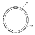
(第2実施例)
図5は、第2実施例のトーンホイール22の正面図であり、図6は、トーンホイール22の一部破断した展開図であり、図7は、図6のA−A線に沿った軸方向要部断面図である。本実施例においても、多板クラッチの主要部分は図1及び図2に示したものと同様である。
【0024】
第2実施例のトーンホイール22は、ほぼ円筒形の環状部材に半径方向に貫通するスリット23を設けたものである。スリット23は、トーンホイール22の軸方向の一端部に開口するように設ける。スリット23は、トーンホイール22の周方向に所定ピッチで設けられている。クラッチケース5が回転すると、このスリット23とスリット23間の部分とが、交互に回転速度検出センサ4に対向する位置を通過する。これにより、回転速度検出センサ4がスリット23を感知すると、回転速度検出センサ4にパルス信号が発生し、クラッチケース5の回転速度が検出できる。
【0025】
図7に示すように、トーンホイール22はスリット23を設けた部分とトーンホイール22をクラッチケース5に接合する接合部24とからなる。スリット23を設けた部分はクラッチケース5の外周面に対して所定の間隔を有する。図7では、左方向がクラッチケース5の開口部になり、接合部24は開口部端でクラッチケース5と接合しているが、この構成は逆にしてもよい。すなわち、スリット23を開口部側になるように配置することもできる。しかしながら、開口部の剛性を高めるという点からは図7のように配置することが好ましい。
【0026】
(第3実施例)
図8は、第3実施例のトーンホイール32の正面図であり、図9は、トーンホイール32の一部破断した展開図であり、図10は、図9のB−B線に沿った軸方向要部断面図である。本実施例においても、多板クラッチの主要部分は図1及び図2に示したものと同様である。
【0027】
第3実施例のトーンホイール32は、ほぼ円筒形の環状部材に半径方向に貫通する孔33を設けたものである。孔33は、ほぼ円形であり、トーンホイール32の周方向に所定ピッチで設けられている。クラッチケース5が回転すると、この孔33と孔33間の部分とが、交互に回転速度検出センサ4に対向する位置を通過する。これにより、回転速度検出センサ4が孔33を感知すると、回転速度検出センサ4にパルス信号が発生し、クラッチケース5の回転速度が検出できる。
【0028】
図10に示すように、トーンホイール32は孔33を設けた外側円筒部36と、クラッチケース5に接合される内側円筒部34と、外側円筒部36と内側円筒部35とを一体に結ぶ円盤部35とを有する。孔33を設けた外側円筒部36はクラッチケース5の外周面に対して所定の間隔を有する。図10では、左方向がクラッチケース5の開口部になり、内側円筒部34は開口部端でクラッチケース5と接合しているが、この構成は逆にしてもよい。すなわち、外側円筒部36を開口部側になるように配置することもできる。しかしながら、開口部の剛性を高めるという点からは図10のように配置することが好ましい。
【0029】
(第4実施例)
図11は、第4実施例のトーンホイール42の正面図であり、図12は、トーンホイール42の一部破断した展開図であり、図13は、図11のC−C線に沿った軸方向要部断面図である。本実施例においても、多板クラッチの主要部分は図1及び図2に示したものと同様である。
【0030】
第4実施例のトーンホイール42は、ほぼ円筒形の環状部材に半径方向に貫通する孔43を設けたものである。孔43は矩形であり、トーンホイール42の周方向に所定ピッチで設けられている。クラッチケース5が回転すると、この孔43と孔43間の部分とが、交互に回転速度検出センサ4に対向する位置を通過する。これにより、回転速度検出センサ4が孔43を感知すると、回転速度検出センサ4にパルス信号が発生し、クラッチケース5の回転速度が検出できる。
【0031】
図13に示すように、トーンホイール42は孔43を設けた円筒部と、クラッチケース5の開口部の軸方向端部に接合されるフランジ部44とを有する。第4実施例では、トーンホイール43全体で開口部に接合されている。従って、クラッチケース5の開口部の剛性を高めるためにより有効である。
【0032】
第4実施例のトーンホイール42は、前述の第1〜第3実施例のものとは異なり、回転速度検出センサ4が検出する窪みの深さはトーンホイール42の材料の厚さ分しかない。このような形態にすることによって装置全体の径方向寸法を拡大しなくて済むという利点がある。
【0033】
以上説明した第1−4実施例のトーンホイールは、筒状の材料にプレス加工を施し、凹凸形状、スリット、孔を設けても良く、また板状の材料にプレス加工を施して凹凸形状、スリット、孔を成形した後、環状に丸めて端部を溶接、ロー付け可締め、リベット等で結合して形成しても良い。
【0034】
また、トーンホイールとクラッチケースとの結合も溶接、ロー付け、可締め、リベット等により行う。尚、板状の材料にプレス加工を施して凹凸形状、スリット、孔を成形した後、クラッチケースの外周に巻付けつつ環状に丸める加工を施しても良い。
【0035】
(第5実施例)
図14は、本発明の第5実施例を示すクラッチケースの正面図であり、図15は、その軸方向断面図である。多板クラッチ40の主要部分は図1及び図2に示したものと同様であるので説明は省く。図14に示すようにクラッチケース5の摩擦係合要素が配置されている部分に対応した外周面には、クラッチケース内周側に設けられたスプラインの形状が表れておらず、ほぼ円筒形の円筒面が形成されている。そして、外周面から内周面へと貫通する油孔16が設けられている。油孔16は、内径側に設けられた不図示のハブから供給される潤滑油が摩擦係合要素を潤滑後、クラッチケース5の外部へと出るための孔である。
【0036】
一方、回転速度検出センサ4は変速機ケース41に取付けられている。回転速度検出センサ4は油孔16に対向して配置され、油孔16の外径側に取付けられている。クラッチケース5が回転すると油孔16と油孔16間の部分とが、交互に回転速度検出センサ4に対向する位置を通過する。これにより、回転速度検出センサ4が油孔16を感知すると、回転速度検出センサ4にパルス信号が発生し、クラッチケース5の回転速度が検出できる。
【0037】
本発明の多板クラッチは、湿式、乾式いずれの形式でも適用できる。また、回転速度検出センサとしては、金属製物体が近づいたり遠ざかったりすることによってセンサ内部の磁気が乱れ、これを検出する電磁式(または磁電式)及び対象物に光をあて反射して戻ってきた光を検出する光電式のいずれのセンサも用いることができる。
【0038】
但し、本発明では、使用環境を考えると潤滑油の影響を受けない電磁式のものが適している。例えば、特許文献1(特開2001−90817号)や特許文献4(実公平6−4121号)などに記載の公知の電磁式センサを用いることができる。
【0039】
尚、回転速度検出センサ4によって検出された回転速度は、電気信号として不図示の制御回路などに入力され、変速機の変速タイミングを制御するためなどに用いられる。本発明の多板クラッチは出力側の部材に取付けられているが、これとは別に入力側(例えば、エンジン)にもう一つ別の回転速度検出センサを取付け、双方の回転速度の差を算出することによってこのタイミングを制御している。
【0040】
【発明の効果】
以上説明した本発明によれば、以下のような効果が得られる。
クラッチケース全体を薄肉に形成した場合には、クラッチケースの開口部の強度が不足してしまうことがあるが、請求項1のようにクラッチケースの外周にトーンホイールを設けたことにより、クラッチケースが補強され、所望の強度を確保することが可能になる。また、トーンホイール、クラッチケース共にプレス成形が可能になるので、生産性が向上する。更に、クラッチケースに設けられたスプラインの凹凸形状の数に関係なく任意の数のパルサー(凹凸部、孔、スリットなど)を設けることができる。請求項2のようにトーンホイールをクラッチケースの開口部側に設置することで、開口部が更に補強され、クラッチケース全体の剛性が向上する。
【0041】
請求項4のように、クラッチケースに設けた油孔を利用することによって、多板クラッチの形態をまったく変えることなく、またクラッチケース外周面に表れたスプラインの凹凸を利用せず、多板クラッチの回転速度の検出が可能になる。また、クラッチケースを円筒形に形成することで、クラッチケースの小型化が可能となると共に、クラッチケースをブレーキバンドの回転ドラムとして用いることが可能となる。
【図面の簡単な説明】
【図1】本発明の各実施例が適用される、開口端側からみた多板クラッチの正面図である。
【図2】図1の多板クラッチの軸方向断面図である。
【図3】第1実施例のトーンホイールの正面図である。
【図4】図1のトーンホイールの側面図である。
【図5】第2実施例のトーンホイールの正面図である。
【図6】図5のトーンホイールの一部破断した展開図である。
【図7】図6のA−A線に沿った軸方向要部断面図である。
【図8】第3実施例のトーンホイールの正面図である。
【図9】図8のトーンホイールの一部破断した展開図である。
【図10】図9のB−B線に沿った軸方向要部断面図である。
【図11】第4実施例のトーンホイールの正面図である。
【図12】図11のトーンホイールの一部破断した展開図である。
【図13】図12のC−C線に沿った軸方向要部断面図である。
【図14】本発明の第5実施例を示すクラッチケースの正面図である。
【図15】図14の軸方向断面図である。
【符号の説明】
2,22,32,42・・・トーンホイール
3・・・セパレータプレート
4・・・回転速度検出センサ
5・・・クラッチケース
7・・・フリクションプレート
9・・・ピストン
16・・・油孔
20,40・・・多板クラッチ[0001]
TECHNICAL FIELD OF THE INVENTION
The present invention relates to a multi-plate clutch used for an automatic transmission such as an automobile. More specifically, the present invention relates to a configuration of a clutch case of a multi-plate clutch and a structure for mounting a rotation speed detection sensor.
[0002]
[Prior art]
Conventionally, various proposals have been made for detecting the rotation speed of a clutch case (drum) of a multi-plate clutch used for an automatic transmission or the like. For example, a rotational speed sensor faces a pulse tooth provided on an outer peripheral surface of a closed end of a clutch case, and when the clutch case rotates, the rotational speed sensor reads a pulse signal generated by the pulse tooth and detects a rotational speed of the clutch case. It has been proposed to. (For example, see
[0003]
Further, it has been proposed to detect a rotational speed of the clutch case by reading a pulse signal generated by unevenness on the outer peripheral surface of the clutch case by using a rotational speed sensor provided close to an outer peripheral surface of a closed end of the clutch case. . (See, for example,
[0004]
The detected rotational speed of the clutch case is input as an electric signal to a control circuit or the like, and is used for controlling shift timing of the transmission. (For example, see Patent Document 5)
[0005]
Prior art document information related to the invention of this application includes the following.
[Patent Document 1]
JP 2001-90817 A (Pages 2-3, FIG. 1 etc.)
[Patent Document 2]
JP-A-10-339368 (pages 2-3, FIG. 3, etc.)
[Patent Document 3]
JP-A-6-17840 (pages 2-3, Fig. 1, etc.)
[Patent Document 4]
Japanese Utility Model Publication No. 6-4121 (
[Patent Document 5]
Japanese Utility Model Publication No. 51-107583 (FIG. 1, etc.)
[0006]
[Problems to be solved by the invention]
The conventional detection device and structure described above have the following problems.
(1) The rotation speed is detected by using the pulse teeth provided on the outer periphery of the clutch case and the irregularities on the outer peripheral surface of the clutch case. For this reason, a predetermined thickness is required for the clutch case in order to maintain desired rigidity, and it has been difficult to reduce the weight of the entire clutch case.
(2) Since an uneven shape is required for detecting the rotational speed, the outer periphery of the clutch case cannot be formed in a cylindrical shape with a simple structure. Therefore, it is difficult to reduce the size of the clutch case, and it is difficult to use the clutch case as a rotating drum of a brake band.
[0007]
Therefore, an object of the present invention is to provide a multi-plate clutch capable of reducing the weight of the entire clutch case while securing the strength of the opening of the clutch case.
Another object of the present invention is to provide a multi-disc clutch having a substantially cylindrical surface portion in which spline unevenness is not formed on the outer peripheral surface of a clutch case, without changing the structure of the multi-disc clutch without rotating the multi-disc clutch. It is an object of the present invention to provide a mounting structure of a rotation speed detection sensor capable of detecting a speed.
[0008]
[Means for Solving the Problems]
In order to achieve the above object, the multi-plate clutch of the present invention
In a multi-plate clutch in which a friction engagement element is arranged in a clutch case and power is transmitted by applying a fastening load to the friction engagement element, a tone wheel is provided on an outer periphery of the clutch case.
[0009]
Further, in order to achieve another object of the present invention, the mounting structure of the rotation speed detection sensor of the present invention,
In a mounting structure of a rotation speed detection sensor for detecting a rotation speed of a multi-plate clutch provided with a clutch case having a substantially cylindrical cylindrical portion on the outer periphery, an oil hole opened on the outer periphery for discharging lubricating oil is provided on the cylindrical portion. A rotation speed detection sensor is provided at a position facing the oil hole, and the rotation speed is detected by detecting the position of the oil hole.
[0010]
DETAILED DESCRIPTION OF THE INVENTION
By providing the tone wheel on the outer periphery of the clutch case, it is not necessary to engrave pulse teeth on the outer periphery of the clutch case or to provide irregularities, so that the entire clutch case can be made thinner and the configuration can be simplified.
[0011]
Since the rotational speed is detected using the oil hole opened on the outer periphery of the clutch case, the outer periphery of the clutch case can be formed in a cylindrical shape. That is, the rotation speed can be detected without changing the shape of the clutch case.
[0012]
【Example】
Hereinafter, embodiments of the present invention will be described in detail with reference to the accompanying drawings. In the drawings, the same parts are denoted by the same reference numerals. In addition, it is needless to say that the embodiments described below merely illustrate the present invention by way of example and do not limit the present invention.
[0013]
1 and 2 show a multiple disc clutch to which each embodiment of the present invention is applied. FIG. 1 is a front view of the multi-plate clutch as viewed from the opening end side, and FIG. 2 is an axial sectional view thereof. FIGS. 1 and 2 show an example in which the tone wheel of the first embodiment is attached.
[0014]
As shown in FIGS. 1 and 2, the
[0015]
A plurality of
[0016]
On the other hand, a piston 9 is provided on the closing side of the
[0017]
A hub (not shown) is provided with a plurality of lubricating oil supply holes (not shown) penetrating in the radial direction, and cools the
[0018]
A
[0019]
The oil is supplied to the
[0020]
When the oil pressure in the
[0021]
As shown in FIG. 1, the
[0022]
(First embodiment)
FIG. 3 is a front view of the
[0023]
(Second embodiment)
FIG. 5 is a front view of the
[0024]
The
[0025]
As shown in FIG. 7, the
[0026]
(Third embodiment)
FIG. 8 is a front view of the
[0027]
The
[0028]
As shown in FIG. 10, the
[0029]
(Fourth embodiment)
FIG. 11 is a front view of the
[0030]
The
[0031]
As shown in FIG. 13, the
[0032]
The
[0033]
The tone wheel according to the first to fourth embodiments described above may be formed by pressing a cylindrical material to form an uneven shape, a slit, and a hole. After the slits and holes are formed, they may be rounded into an annular shape, and the ends may be welded, brazed and fastened together by rivets or the like.
[0034]
The connection between the tone wheel and the clutch case is also performed by welding, brazing, tightening, rivets, or the like. After the plate-shaped material is pressed to form irregularities, slits, and holes, the material may be rounded into an annular shape while being wound around the outer periphery of the clutch case.
[0035]
(Fifth embodiment)
FIG. 14 is a front view of a clutch case showing a fifth embodiment of the present invention, and FIG. 15 is an axial sectional view thereof. The main part of the multi-plate clutch 40 is the same as that shown in FIGS. As shown in FIG. 14, the shape of the spline provided on the inner peripheral side of the clutch case does not appear on the outer peripheral surface corresponding to the portion where the frictional engagement element of the
[0036]
On the other hand, the rotation
[0037]
The multi-plate clutch of the present invention can be applied in any of a wet type and a dry type. In addition, as a rotation speed detection sensor, when a metal object approaches or moves away, the magnetism inside the sensor is disturbed, and an electromagnetic (or magnetoelectric) sensor that detects this is reflected by reflecting light on an object and returning. Any photoelectric sensor that detects the reflected light can be used.
[0038]
However, in the present invention, an electromagnetic type which is not affected by lubricating oil is suitable in consideration of a use environment. For example, known electromagnetic sensors described in Patent Document 1 (Japanese Patent Application Laid-Open No. 2001-90817) and Patent Document 4 (Japanese Utility Model Publication No. 6-4121) can be used.
[0039]
The rotation speed detected by the rotation
[0040]
【The invention's effect】
According to the present invention described above, the following effects can be obtained.
When the entire clutch case is formed to be thin, the strength of the opening of the clutch case may be insufficient. However, the provision of the tone wheel on the outer periphery of the clutch case as described in
[0041]
By using the oil hole provided in the clutch case as in
[Brief description of the drawings]
FIG. 1 is a front view of a multiple disc clutch as viewed from an open end to which each embodiment of the present invention is applied.
FIG. 2 is an axial sectional view of the multi-plate clutch shown in FIG. 1;
FIG. 3 is a front view of the tone wheel according to the first embodiment.
FIG. 4 is a side view of the tone wheel of FIG. 1;
FIG. 5 is a front view of a tone wheel according to a second embodiment.
FIG. 6 is a partially exploded development view of the tone wheel of FIG. 5;
7 is a cross-sectional view of a main part in the axial direction along the line AA in FIG. 6;
FIG. 8 is a front view of a tone wheel according to a third embodiment.
FIG. 9 is a partially exploded development view of the tone wheel of FIG. 8;
FIG. 10 is a cross-sectional view of a main part in the axial direction along line BB in FIG. 9;
FIG. 11 is a front view of a tone wheel according to a fourth embodiment.
FIG. 12 is a partially exploded development view of the tone wheel of FIG. 11;
13 is a cross-sectional view of a main part in the axial direction along the line CC of FIG. 12;
FIG. 14 is a front view of a clutch case showing a fifth embodiment of the present invention.
15 is an axial sectional view of FIG.
[Explanation of symbols]
2, 22, 32, 42 ...
Claims (4)
前記クラッチケースの外周にトーンホイールを設けたことを特徴とする多板クラッチ。In a multi-plate clutch in which a friction engagement element is arranged in a clutch case and power is transmitted by applying a fastening load to the friction engagement element,
A multi-plate clutch, wherein a tone wheel is provided on an outer periphery of the clutch case.
前記円筒部分には潤滑油を排出するため外周に開口した油孔が設けられており、前記油孔に対向する位置に回転速度検出センサを取付け、前記油孔の位置を検知することによって回転速度を検出することを特徴とする回転速度検出センサの取付け構造。In a mounting structure of a rotation speed detection sensor for detecting a rotation speed of a multi-plate clutch including a clutch case having a substantially cylindrical cylindrical portion on the outer periphery,
The cylindrical portion is provided with an oil hole opened on the outer periphery for discharging the lubricating oil. A rotation speed detection sensor is mounted at a position facing the oil hole, and the rotation speed is detected by detecting the position of the oil hole. A structure for mounting a rotational speed detection sensor, characterized by detecting a rotational speed.
Priority Applications (2)
| Application Number | Priority Date | Filing Date | Title |
|---|---|---|---|
| JP2002336488A JP2004169813A (en) | 2002-11-20 | 2002-11-20 | Multi-plate clutch, and rotational speed detecting sensor attaching structure |
| US10/712,099 US20040094383A1 (en) | 2002-11-20 | 2003-11-14 | Multi-plate clutch and rotational speed detecting sensor attaching structure |
Applications Claiming Priority (1)
| Application Number | Priority Date | Filing Date | Title |
|---|---|---|---|
| JP2002336488A JP2004169813A (en) | 2002-11-20 | 2002-11-20 | Multi-plate clutch, and rotational speed detecting sensor attaching structure |
Publications (1)
| Publication Number | Publication Date |
|---|---|
| JP2004169813A true JP2004169813A (en) | 2004-06-17 |
Family
ID=32290363
Family Applications (1)
| Application Number | Title | Priority Date | Filing Date |
|---|---|---|---|
| JP2002336488A Pending JP2004169813A (en) | 2002-11-20 | 2002-11-20 | Multi-plate clutch, and rotational speed detecting sensor attaching structure |
Country Status (2)
| Country | Link |
|---|---|
| US (1) | US20040094383A1 (en) |
| JP (1) | JP2004169813A (en) |
Cited By (3)
| Publication number | Priority date | Publication date | Assignee | Title |
|---|---|---|---|---|
| JP2006083984A (en) * | 2004-09-17 | 2006-03-30 | Toyota Motor Corp | Clutch device of automatic transmission |
| JP2007062726A (en) * | 2005-08-29 | 2007-03-15 | Zahnradfab Friedrichshafen Ag | Power transmitting system of hybrid car |
| JP2013155849A (en) * | 2012-01-31 | 2013-08-15 | Aisin Aw Co Ltd | Transmission |
Families Citing this family (12)
| Publication number | Priority date | Publication date | Assignee | Title |
|---|---|---|---|---|
| JP2005273769A (en) * | 2004-03-24 | 2005-10-06 | Jatco Ltd | Automatic transmission |
| JP4006425B2 (en) * | 2004-09-06 | 2007-11-14 | ジヤトコ株式会社 | Automatic transmission |
| FR2879702A1 (en) * | 2004-12-17 | 2006-06-23 | Renault Sas | Dual clutch system for motor vehicle, has drive flange driving external cover and carrying reluctor, at its free end, that emits signal representing speed of rotation of drive flange |
| US7556131B2 (en) * | 2005-11-15 | 2009-07-07 | Caterpillar Inc. | Transmission housing |
| FR2894309A1 (en) * | 2005-12-07 | 2007-06-08 | Renault Sas | MULTIDISTIC CLUTCH FOR A GEARBOX OF MOTOR VEHICLE, AND ASSOCIATED GEARBOX. |
| JP4843699B2 (en) * | 2009-07-15 | 2011-12-21 | ジヤトコ株式会社 | Automatic transmission |
| JP4837763B2 (en) * | 2009-07-15 | 2011-12-14 | ジヤトコ株式会社 | Belt type continuously variable transmission |
| US9234585B2 (en) | 2010-12-20 | 2016-01-12 | Caterpillar Inc. | Transmission housing |
| CA2850297C (en) * | 2013-05-03 | 2019-09-03 | Checkfluid Inc. | Oil port position sensing device |
| US20180045750A1 (en) * | 2016-08-12 | 2018-02-15 | GM Global Technology Operations LLC | Transmission components with a magnetic coating |
| US10400833B1 (en) * | 2017-12-06 | 2019-09-03 | Ronald Wayne Wolverton | Clutch piston assembly for increasing clamping force |
| WO2022176472A1 (en) * | 2021-02-22 | 2022-08-25 | ジヤトコ株式会社 | Sensor arrangement structure |
Family Cites Families (7)
| Publication number | Priority date | Publication date | Assignee | Title |
|---|---|---|---|---|
| EP0251009B1 (en) * | 1986-07-02 | 1990-05-30 | Siemens Aktiengesellschaft | Wheel for an angular pulse generator |
| US5053656A (en) * | 1989-12-18 | 1991-10-01 | Ina Bearing Company, Inc. | Sensing ring for rotational sensing system |
| JP2777951B2 (en) * | 1992-06-30 | 1998-07-23 | 本田技研工業株式会社 | Manufacturing method and manufacturing apparatus for clutch drum |
| JPH08146021A (en) * | 1994-11-16 | 1996-06-07 | Nissan Motor Co Ltd | Structure for mounting rotor for abs wheel rotation sensor, and manufacture of the rotor |
| DE19756451C1 (en) * | 1997-12-18 | 1998-12-24 | Mannesmann Sachs Ag | Motor vehicle friction clutch wear detection method |
| DE19827339C2 (en) * | 1998-06-19 | 2000-04-20 | Sachs Race Eng Gmbh | Housing for a multi-plate clutch |
| DE10243991A1 (en) * | 2002-09-21 | 2004-04-01 | Sachs Race Engineering Gmbh | Trigger arrangement for a friction clutch |
-
2002
- 2002-11-20 JP JP2002336488A patent/JP2004169813A/en active Pending
-
2003
- 2003-11-14 US US10/712,099 patent/US20040094383A1/en not_active Abandoned
Cited By (4)
| Publication number | Priority date | Publication date | Assignee | Title |
|---|---|---|---|---|
| JP2006083984A (en) * | 2004-09-17 | 2006-03-30 | Toyota Motor Corp | Clutch device of automatic transmission |
| JP4691932B2 (en) * | 2004-09-17 | 2011-06-01 | トヨタ自動車株式会社 | Automatic transmission clutch device |
| JP2007062726A (en) * | 2005-08-29 | 2007-03-15 | Zahnradfab Friedrichshafen Ag | Power transmitting system of hybrid car |
| JP2013155849A (en) * | 2012-01-31 | 2013-08-15 | Aisin Aw Co Ltd | Transmission |
Also Published As
| Publication number | Publication date |
|---|---|
| US20040094383A1 (en) | 2004-05-20 |
Similar Documents
| Publication | Publication Date | Title |
|---|---|---|
| JP2004169813A (en) | Multi-plate clutch, and rotational speed detecting sensor attaching structure | |
| JP4837763B2 (en) | Belt type continuously variable transmission | |
| US7566287B2 (en) | Clutch device for automatic transmission | |
| US7967123B2 (en) | Wet-type multi-plate friction engaging apparatus | |
| US7966901B2 (en) | Torque transfer device | |
| JP2007155096A (en) | Wet type multiple disc clutch | |
| JP2010127341A (en) | Wave spring holding structure and frictional engagement apparatus | |
| JP2017503132A (en) | Friction-type shift element for vehicle transmission | |
| JPS5930928B2 (en) | adapter ring | |
| JP2007292087A (en) | Fluid type torque transmission device and lock-up device used for the same | |
| JPH1163152A (en) | Torque converter | |
| JP2007218308A (en) | Wet type multiple disc clutch | |
| US11879504B1 (en) | Clutch device and motorcycle | |
| US11933368B1 (en) | Clutch device and motorcycle | |
| US20240011531A1 (en) | Clutch device and motorcycle | |
| JP4066246B2 (en) | Multi-plate clutch | |
| JPH0320588Y2 (en) | ||
| JP2000266079A (en) | Wet frictional member and frictional disc | |
| JP2004251372A (en) | Multiplate wet clutch | |
| US11946513B1 (en) | Clutch device and motorcycle | |
| US11940013B1 (en) | Clutch device and motorcycle | |
| US11841053B1 (en) | Clutch device | |
| US11788583B1 (en) | Clutch device and motorcycle | |
| US20240026935A1 (en) | Clutch device | |
| JP2005264961A (en) | Lock-up mechanism for torque converter |
Legal Events
| Date | Code | Title | Description |
|---|---|---|---|
| A621 | Written request for application examination |
Free format text: JAPANESE INTERMEDIATE CODE: A621 Effective date: 20051102 |
|
| A977 | Report on retrieval |
Free format text: JAPANESE INTERMEDIATE CODE: A971007 Effective date: 20071228 |
|
| A131 | Notification of reasons for refusal |
Free format text: JAPANESE INTERMEDIATE CODE: A131 Effective date: 20080303 |
|
| A02 | Decision of refusal |
Free format text: JAPANESE INTERMEDIATE CODE: A02 Effective date: 20080730 |