JP2004167883A - Portable power tool with lighting device - Google Patents
Portable power tool with lighting device Download PDFInfo
- Publication number
- JP2004167883A JP2004167883A JP2002337218A JP2002337218A JP2004167883A JP 2004167883 A JP2004167883 A JP 2004167883A JP 2002337218 A JP2002337218 A JP 2002337218A JP 2002337218 A JP2002337218 A JP 2002337218A JP 2004167883 A JP2004167883 A JP 2004167883A
- Authority
- JP
- Japan
- Prior art keywords
- power tool
- led
- portable
- circular saw
- base
- Prior art date
- Legal status (The legal status is an assumption and is not a legal conclusion. Google has not performed a legal analysis and makes no representation as to the accuracy of the status listed.)
- Withdrawn
Links
Images


Landscapes
- Sawing (AREA)
Abstract
【課題】本発明の課題は、粉塵などの多い作業環境においても、作業者が、切断位置を示す墨線をはっきり見ることができ、正確な作業ができる携帯用電動工具を提供することである。
【解決手段】切断部、加工部等の所望の領域を照明する照明装置を備えた携帯用電動工具において、上記照明装置として発光波長が550nmから620nmの範囲にある単色光を発光するLEDを用いた。
【選択図】 図1An object of the present invention is to provide a portable power tool that enables an operator to clearly see a black line indicating a cutting position and to perform an accurate operation even in a work environment where much dust or the like is present.
A portable power tool provided with an illuminating device for illuminating a desired area such as a cutting portion or a processing portion, wherein the illuminating device uses an LED that emits monochromatic light having an emission wavelength in the range of 550 nm to 620 nm. Was.
[Selection diagram] Fig. 1
Description
【0001】
【発明の属する技術分野】
本発明は携帯用電動工具に係り、特に切断部、加工部あるいはその周辺を照らすための照明装置を備えた電動工具に関するものである。
【0002】
【従来の技術】
【特許文献1】特開平11−170203号公報
【特許文献2】実開昭60−98602号公報
【特許文献3】特開2001−300818号公報
【特許文献4】米国特許第5,461,790号公報
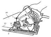
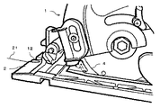
電動丸のこは被削材に書かれた墨線に沿ってその被削材を切断する用途に多用されている。図10は携帯用集塵丸のこ1により被削材20を切断している状況を示しており、ベース2に設けられた切込部12を墨線21に合わせて丸のこ本体1を移動することにより鋸刃4が墨線21に沿って被削材20を切断する。図11は一部を拡大して示したもので鋸刃4が被削材を切断する際、多量の切粉が発生する状況を示している。このように粉塵の多い環境の中でも精度の高い作業ができるように携帯用電動工具に照明装置をつける構造が提案されている。
【0003】
実開昭60−98602(特許文献2)には電動丸のこを使って精度の高い作業を行うために回転刃の保護カバーに透明窓を有する照明器を取り付け、その内部に電球を配設した構造が開示されている。
【0004】
また特開平11−170203(特許文献1)にはのこ刃の刃先の視認性及び組立性の向上性を図るため、のこ刃の刃先をのこ刃の切断方向に対して直角方向に照らす電球を設けた携帯用丸のこが開示されている。
【0005】
更に特開2001−300818(特許文献3)には、切断加工により切り粉が巻き上げられても照明効率が低下しにくいようにするため、切断刃に対して面直方向にずれた位置に電球を配置した携帯用丸のこが開示されている。
【0006】
また米国特許第5,461,790(特許文献4)には、丸のこを用いてより精度の高い切断を行うために、のこ刃のシールド部にレーザダイオードを設けた構造が開示されており、そのダイオードの発光波長が630〜670nmのものが使用されるという記載がある。
【0007】
【発明が解決しようとする課題】
上述の特許文献1、2、3に開示された電動丸のこはいずれも照明装置として電球を用いているが、電球はスペースをとるためにその設置場所に制約があるという欠点があり、また振動の激しい電動工具に用いる場合は頻繁に断線を生じ易いという問題があった。
【0008】
一方、特許文献4に記載されているようなレーザダイオードは上記のような問題がなく小型で且つ光の指向性も大きいため、切断部などを局所的に照明する場合に適している。しかしながら特許文献4に記載されている波長が630〜670nmのレーザダイオードを実際に用いてみると、必ずしも視認性に優れているとは言えないことが判明した。
【0009】
一般的に人間の眼は明るい環境では555nmの緑の波長に最も効率より反応することが知られている。また人間の眼は暗い環境で活発に反応する細胞と、明るい環境で活発に反応する細胞の二種類があるため、暗いところでは青色の光を明るく感じ、明るいところでは赤色を明るく感じることも知られている。
【0010】
図2は人間の眼の比視感度特性を示すもので横軸に光の波長、縦軸に比視感度をとってある。この図から暗い場所では波長が500nm程度の色に感度が高いが、明るい場所になるに従って感度の高い色は、より波長の長い色に移ることが分かる。
【0011】
通常電動工具は昼間に用いられることが多いから赤色は見やすいはずであるが、実際には意外に視認性がよくない原因はいろいろ考えられる。その一つは、電動工具に用いられる照明装置の特殊性にあると考えられる。すなわち電動工具の照明装置は単に周囲を明るくするという一般の照明と異なり鉛筆などで書かれた特定の線、つまり墨線を見やすくするということに主たる目的がある。例えば電動丸のこの場合は被削材に予め書かれた墨線に沿って正確に切断することが要求され、また携帯用ドライバの場合は、ねじ締め位置に鉛筆などで書かれた目印に正確にねじを位置合わせして、ねじ締め作業を行うことが要求される。この被削材あるいは被加工部に書かれる墨線や目印は通常黒色であるため、この線に赤色光を照射したときに黒が見えにくくなるということが考えられる。
【0012】
一方、赤色発光ダイオードに代えて、白色のLEDを用いて実験をしたところ、これにも問題があることが判明した。この白色LEDは青色LEDと蛍光体を組み合わせ結果的に青色と黄色の光を混合することにより白色を発光させるものである。
【0013】
この白色LEDを電動丸のこに用いて切断したところ墨線が見にくいことが確認された。またこの白色LEDを粉塵が大量に発生する電動工具、例えば、携帯用集塵丸のこに用いたところ、撒き散らされる粉塵や集塵機に集塵されつつある粉塵に白色光が照射されて乱反射が起こり、刃先及び刃先前方の墨線を確認することができないという不具合があった。
【0014】
本発明は上記のような問題を解決した携帯用電動工具を提供することを目的とする。すなわち、本発明は被削材あるいは加工物に書かれた墨線が見易く、しかも粉塵が多量に存在する作業環境でも目視したい箇所が見易い照明装置を備えた電動工具を提供することを目的とするものである。
【0015】
【課題を解決するための手段】
本発明者は課題解決にあたりトンネルの中の照明として一般的に採用されているナトリウム灯に着目した。即ちトンネルの中は粉塵が舞い易く、排気ガスが充満した環境にあるため、電動工具が使用される環境とアナロジーがある可能性がある。また、霧など乱反射が生じ易いときに使用される自動車のフォグランプにも着目した。即ち霧と粉塵とは異なるが、いずれも乱反射を起こし易い環境にあることは共通しているからである。本発明者は電動工具が使用される場所とは全く異なるが上述のいずれの環境においても黄色または橙色のランプが使用されていることに着目し、検討を加えた結果、請求項記載の発明に到達した。
【0016】
請求項1に記載された本発明は、切断部、加工部等の所望の領域を照明する照明装置を備えた携帯用電動工具において、上記照明装置として発光波長が550nmから620nmの範囲にある単色光を発光するLEDを用いたことに一つの特徴がある。
【0017】
本発明の他の特徴は、ベースと、該ベースに対して傾斜可能に支持された丸のこ本体とよりなる携帯用丸のこにおいて、鋸刃の刃先部を照射する第1のLEDと、上記ベースの先端部を照射する第2のLEDとを備え、上記第1及び第2のLEDとして発光波長が550nmから620nmの範囲にある光を発光するLEDを用いたことにある。
【0018】
本発明の他の特徴は、上記の第1及び第2のLEDを駆動するための駆動回路を有し、駆動回路は上記刃先部及びベース先端部の照度が100ルクス以上となるように上記第1及び第2のLEDを駆動し、さらに望ましくは、140ルクス以上となるように上記第1及び第2のLEDを駆動するように構成したことにある。
本発明の他の特徴及び利点は以下の実施形態の説明からさらに明確に理解される。
【0019】
【発明の実施の形態】
本発明は各種の電動工具に適用可能であるが、特に携帯用集塵丸のこに適用したときに特に大きな効果が得られるので以下携帯用集塵丸のこの実施例について説明する。
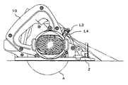
図1は本発明の実施例を示す正面図、図3はその上面から見た平面図、図4は背面図である。携帯用集塵丸のこは丸のこ本体1と、切断すべき被削材の上面に載せるベース2とを備えている。丸のこ本体1はベース2に対して傾斜ができるように支持部3を支点として回動可能に支持されている。4は円形の鋸刃で丸のこ本体に回動可能に保持され、電動機(図示せず)を動力として回転駆動する。鋸刃4の上側と側方はソーカバー5により覆われている。
【0020】
鋸刃4の回転軸6にはセーフティーカバー7が回動可能に取り付けられて、これにより鋸刃4の下側ほぼ半周の範囲がカバーされる。丸のこ本体1を切断進行方向に移動させると回動して鋸刃4の下側半分が徐々に露出されるように構成されている。
【0021】
鋸刃4の側面部にはギヤケース8が設けられている。このギヤケース8内には電動機カバー9内に設けられた電動機の回転を減速させるための歯車(図示せず)が内蔵されている。電動機の回転は上記ギヤケース8内の歯車を介して鋸刃4の回転軸6に伝達されることにより鋸刃4が回転する。鋸刃4の回転により被削材を切断することにより発生した粉塵は管状をした粉塵排出口11から外部に放出される。
【0022】
本実施形態においては照明用のLEDが4個搭載されている。2個のLEDL1、L2は鋸刃4とハンドル部10の間の丸のこ本体1の下部に位置し、鋸刃4に近接して配置されている。このLEDL1、L2は鋸刃4が被削材上面に描かれた墨線に沿って切断しているかどうか確認できるように、鋸刃4と被削材とが接触している部分及びその周辺の領域を照射する(図1)。
【0023】
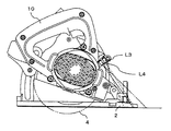
一方他の2個のLEDL3、L4は鋸刃4とハンドル部10の間の丸のこ本体の上部に位置し(図4)、ベース2の前方を照射する。すなわち、このLEDL3、L4はベース2に設けられた切込部12が被削物の上面に描かれた墨線に沿って移動しているかどうかを確認できるように丸のこ本体1の進行方向であってベース2に近接した領域を照射するために設けられている。
【0024】
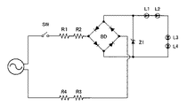
図5は上記LEDL1〜L4を駆動する回路の一実施例を示す。電源からの電圧はスイッチSW及び抵抗R1、R2、R3、R4を介してダイオードブリッジ回路BDの一対の端子に印加される。このブリッジ回路BDにより整流された電圧はブリッジBDの他の一対の端子より取り出されツェナーダイオードZ1により定電圧化された後、LEDL1〜L4に加えられる。この電気回路は丸のこ本体1の鋸刃4とハンドル部10との間の一部の空間に収納されている。
【0025】
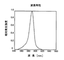
本発明では上記LEDL〜L4として発光波長が550nmから620nmの範囲にある単色光の発光ダイオードが使用される。図9は既に市販されている黄色(あるいは橙色)の発光をするLEDの波長特性を示しているが、この発光色が多量の粉塵中で墨線を目視するときに、最も視認性のよいことが確認された。なお、約90名を対象に視認性の良さについて確認を行ったが、ほぼ全員が白色LEDよりも本発明のLEDの方が見易い、即ち視認性に優れていると評価した。
【0026】
この理由はいろいろ考えられるが、図2に示した比視感度が550nm〜620nmの領域でかなり高いこと、また単色光であるため木材などからの反射が少ないこと、また多量の粉塵の中で乱反射することがないこと等が原因と考えられる。なお、霧など乱反射が生じ易いときに使用される自動車のフォグランプも、黄色または橙色を採用しており、黒を際立たせる色として黄色が効果的であることも一つの理由と考えられる。
【0027】
次に本発明装置における照明装置の照度について説明する。
図6及び図7はそれぞれ図1及び図4の状態から鋸刃4の切り込み深さを小さくした状態を示す正面図と背面図であり図8は図4の平面図である。切り込みが深い場合、図1に示すように刃先部用のLEDL1,L2は被削材に極めて近接しているので照度が大きいが、図6のように切り込み深さを小さくするとLEDL1、L2が被削材から若干離れるために照度は低下する。本発明の実施例のように刃先部用に2個のLEDを用いた場合、切り込み時が9mmと浅い場合でもベース底面で140ルクスが得られた。最大切込み時はこの2倍以上の照度が得られた。
【0028】
またベース先端部を照明するためのLEDL3、L4は上下に2個配置され、上部にあるLEDL3によりベース2に最も近接した領域を照らし、下部にあるLEDL4は上記領域よりベース2から離れた領域を照らすように配置されている。このLEDL3、L4は図4に示すように鋸刃4の切込み深さが深い場合よりも図7に示すように切込み深さか浅い方が被削材を真上に近い部所から照射するようになり照度が大きくなる。
【0029】
本発明の実施例のように2個のLEDL3、L4を上下方向に配列した場合、最大切込み深さの状態でもベース底面で140ルクスが得られた。切込み深さが9mm程度と浅い場合にはこの照度が30%程度高くなる。従って本発明装置の実施例では刃先部及びベース先端部の照度が最も低い場合でも140ルクス程度を確保でき、極めて多量の粉塵が発生しても墨線の目視に支障がないことが確認された。この照度は高い程良いが、最低でも100ルクス程度あることが望ましいことも確認された。
【0030】
なお、上記実施形態では、発光ダイオードLEDL1〜L4の発光波長が550nmから620nmの範囲内にある例を挙げたが、全ての発光波長が550nmから620nmの範囲内になくとも、最大発光強度を有する光の波長が550nmから620nmの範囲内にある単色光の発光ダイオードであれば、上記実施形態と同様の効果を奏し得るものである。
【0031】
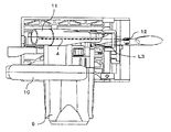
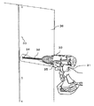
以上本発明の一実施形態について述べたが、本発明の基本的な考え方を変更しない範囲で種々の変形をなし得ることは当然である。例えば、上述の実施形態では刃先部照明用のLEDとベース先端部照明用のLEDを設けたがいずれか一方を設けるようにしてもよい。また実施形態では携帯用集塵丸のこの例について述べたが一般的な電動工具に本発明を適用することは可能である。図12は一例として本発明をドライバドリルに適用した例を示す。本体部30から垂下するハンドル部31の上方であってビット32の先端部を照明するようにLED35が取り付けられている。これにより加工板36に描かれた目印のマーク33に合わせてネジ34を締め付ける作業が正確かつスムースに行うことが可能になる。
【0032】
本発明はこのようにいろいろな種類の電動工具に適用できるが、単にねじを締めたり釘を打ったりする工具より被削材を切断する工具に適用した場合の方が大きな効果を発揮する。
【0033】
【発明の効果】
本発明によれば、照明装置の光源を、黄色、又は橙色の単色光にしたので、粉塵などの多い作業環境においても、作業者が、切断位置を示す墨線をはっきり見ることができ、正確な作業ができる。また、薄い墨線、ねじ締め位置の目印でも、十分に確認がすることができ、墨線の引き直し、目印の付け直しなど、不要の作業をなくすことができるので作業性の向上を図ることができ、作業性の良い携帯用電動工具を提供することができる。
【図面の簡単な説明】
【図1】本発明にかかる電動工具の一実施例を示す正面図。
【図2】比視感度特性の説明図。
【図3】本発明にかかる電動工具の一実施例を示す平面図。
【図4】本発明にかかる電動工具の一実施例を示す背面図。
【図5】本発明にかかる電動工具に用いられるLEDの駆動回路図。
【図6】本発明にかかる電動工具の一実施例を示す正面図。
【図7】本発明にかかる電動工具の一実施例を示す背面図。
【図8】本発明にかかる電動工具の一実施例を示す平面図。
【図9】本発明にかかる電動工具に用いられるLEDの波長特性図。
【図10】携帯用集塵丸のこで被削材を切断している状態を示す説明図。
【図11】携帯用集塵丸のこで被削材を切断している状態を示す一部拡大図。
【図12】本発明をドライバドリルに適用した例を示す説明図。
【符号の説明】
1:丸のこ本体
2:ベース
3:支持軸
4:鋸刃
5:ソーカバー
6:回転軸
7:セーフティーカバー
8:ギヤケース
9:電動機カバー
10:ハンドル部
11:粉塵排出口
12:ベースカバー切込部
L1〜L4:LED[0001]
TECHNICAL FIELD OF THE INVENTION
The present invention relates to a portable power tool, and more particularly, to a power tool having an illumination device for illuminating a cutting portion, a processing portion, or a periphery thereof.
[0002]
[Prior art]
[Patent Document 1] JP-A-11-170203 [Patent Document 2] Japanese Utility Model Application Laid-Open No. 60-98602 [Patent Document 3] JP-A-2001-300818 [Patent Document 4] US Pat. No. 5,461,790 The electric circular saw is widely used for cutting a work material along a black line written on the work material. FIG. 10 shows a state in which the
[0003]
In Japanese Utility Model Application Laid-Open No. 60-98602 (Patent Document 2), an illuminator having a transparent window is attached to a protective cover of a rotary blade in order to perform high-precision work using an electric circular saw, and a light bulb is disposed inside the illuminator. A disclosed structure is disclosed.
[0004]
Japanese Patent Application Laid-Open No. 11-170203 (Patent Document 1) discloses that the edge of a saw blade is illuminated in a direction perpendicular to the cutting direction of the saw blade in order to improve the visibility and assemblability of the saw blade. A portable circular saw provided with a light bulb is disclosed.
[0005]
Further, in Japanese Patent Application Laid-Open No. 2001-300818 (Patent Document 3), in order to make it difficult for the lighting efficiency to be reduced even when the cutting powder is wound up by the cutting process, the electric bulb is placed at a position shifted in a direction perpendicular to the plane with respect to the cutting blade. An arranged portable circular saw is disclosed.
[0006]
Also, US Pat. No. 5,461,790 (Patent Document 4) discloses a structure in which a laser diode is provided in a shield portion of a saw blade in order to perform more accurate cutting using a circular saw. There is a description that a diode having a light emission wavelength of 630 to 670 nm is used.
[0007]
[Problems to be solved by the invention]
The electric circular saws disclosed in the above-mentioned
[0008]
On the other hand, the laser diode described in
[0009]
It is generally known that the human eye responds most efficiently to a green wavelength of 555 nm in a bright environment. In addition, the human eye has two types of cells, one that actively reacts in a dark environment and the other that actively reacts in a bright environment.Therefore, it is known that the human eye feels blue light brightly in dark places and red light brightly in bright places. Have been.
[0010]
FIG. 2 shows the relative luminous efficiency characteristics of the human eye, in which the horizontal axis represents the light wavelength and the vertical axis represents the relative luminous efficiency. From this figure, it can be seen that in a dark place, the sensitivity is high for a color having a wavelength of about 500 nm, but in a bright place, a color having a high sensitivity shifts to a color having a longer wavelength.
[0011]
Normally, power tools are often used in the daytime, so red should be easy to see, but in reality there are many possible causes of poor visibility. One of the reasons is considered to be the specialty of the lighting device used for the power tool. In other words, the main purpose of the lighting device of the power tool is to make it easy to see a specific line written with a pencil or the like, that is, a black line, unlike general lighting that simply brightens the surroundings. For example, in the case of an electric circle, it is required to cut accurately along the black line written on the work material in advance, and in the case of a portable driver, it is necessary to accurately mark with a pencil etc. at the screw tightening position It is required to align the screws and perform the screw tightening operation. Since the black line or mark written on the work material or the processed portion is usually black, it is conceivable that when this line is irradiated with red light, black becomes difficult to see.
[0012]
On the other hand, when an experiment was performed using a white LED instead of the red light emitting diode, it was found that this also had a problem. This white LED emits white light by combining a blue LED and a phosphor, and consequently mixing blue and yellow light.
[0013]
When this white LED was cut using an electric circular saw, it was confirmed that the black line was difficult to see. In addition, when this white LED is used for a power tool that generates a large amount of dust, for example, a portable dust collecting saw, the white light is radiated to the scattered dust and the dust being collected by the dust collector, and irregular reflection is caused. As a result, there was a problem that the cutting edge and the black line in front of the cutting edge could not be confirmed.
[0014]
An object of the present invention is to provide a portable power tool that solves the above problems. That is, an object of the present invention is to provide a power tool provided with a lighting device that makes it easy to see a black line written on a work material or a workpiece, and also to easily see a portion to be visually observed even in a work environment where a large amount of dust is present. It is.
[0015]
[Means for Solving the Problems]
In order to solve the problem, the present inventor focused on a sodium lamp generally used as illumination in a tunnel. That is, since the dust is likely to fly in the tunnel and is in an environment filled with exhaust gas, there is a possibility that there is analogy with the environment in which the power tool is used. We also focused on fog lamps for automobiles that are used when diffuse reflection is likely to occur, such as fog. That is, although fog and dust are different, it is common that both are in an environment where irregular reflection easily occurs. The present inventor focused on the fact that a yellow or orange lamp was used in any of the above-mentioned environments, although it was completely different from the place where the power tool was used. Reached.
[0016]
The present invention described in claim 1 is a portable electric tool provided with an illuminating device for illuminating a desired area such as a cut portion or a processed portion, wherein the illuminating device has a monochromatic color having an emission wavelength in a range of 550 nm to 620 nm. There is one feature in using an LED that emits light.
[0017]
Another feature of the present invention is that in a portable circular saw comprising a base and a circular saw body that is tiltably supported with respect to the base, a first LED that irradiates a blade edge of a saw blade, A second LED that irradiates the tip of the base; and an LED that emits light having an emission wavelength in the range of 550 nm to 620 nm is used as the first and second LEDs.
[0018]
Another feature of the present invention is to have a drive circuit for driving the first and second LEDs, and the drive circuit is configured to drive the first and second LEDs so that the illuminance of the blade edge portion and the base tip portion becomes 100 lux or more. The configuration is such that the first and second LEDs are driven, and more desirably, the first and second LEDs are driven so as to be 140 lux or more.
Other features and advantages of the present invention will be more clearly understood from the following description of the embodiments.
[0019]
BEST MODE FOR CARRYING OUT THE INVENTION
Although the present invention can be applied to various power tools, a particularly great effect is obtained when the present invention is applied to a portable dust collecting saw, and this embodiment of the portable dust collecting round will be described below.
FIG. 1 is a front view showing an embodiment of the present invention, FIG. 3 is a plan view seen from above, and FIG. 4 is a rear view. The portable dust collecting circular saw has a circular saw main body 1 and a
[0020]
A
[0021]
A gear case 8 is provided on a side surface of the
[0022]
In this embodiment, four LEDs for illumination are mounted. The two LEDs L <b> 1 and L <b> 2 are located at the lower part of the circular saw body 1 between the
[0023]
On the other hand, the other two LEDs L3 and L4 are located at the upper part of the circular saw body between the
[0024]
FIG. 5 shows an embodiment of a circuit for driving the LEDs L1 to L4. The voltage from the power supply is applied to a pair of terminals of the diode bridge circuit BD via the switch SW and the resistors R1, R2, R3, R4. The voltage rectified by the bridge circuit BD is taken out from another pair of terminals of the bridge BD, is made constant by the Zener diode Z1, and is applied to the LEDs L1 to L4. This electric circuit is housed in a partial space between the
[0025]
In the present invention, monochromatic light emitting diodes having an emission wavelength in the range of 550 nm to 620 nm are used as the LEDs L to L4. FIG. 9 shows the wavelength characteristics of a commercially available LED that emits yellow (or orange) light. This luminescent color has the best visibility when viewing the black line in a large amount of dust. confirmed. In addition, about 90 persons were checked about the good visibility, but almost all evaluated that the LED of the present invention was easier to see than the white LED, that is, was superior in visibility.
[0026]
There are various possible reasons for this, but the relative luminous efficiency shown in FIG. 2 is considerably high in the region of 550 nm to 620 nm, and because it is monochromatic light, there is little reflection from wood and the like, and irregular reflection in a large amount of dust. This is probably due to the fact that no action is taken. In addition, the fog lamps of automobiles used when diffuse reflection is likely to occur, such as fog, also employ yellow or orange, which is considered to be one reason that yellow is effective as a color that makes black stand out.
[0027]
Next, the illuminance of the lighting device in the device of the present invention will be described.
6 and 7 are a front view and a rear view, respectively, showing a state in which the cutting depth of the
[0028]
Also, two LEDs L3 and L4 for illuminating the base distal end are arranged vertically, and the upper LEDL3 illuminates the area closest to the
[0029]
When the two LEDs L3 and L4 are vertically arranged as in the embodiment of the present invention, 140 lux was obtained on the bottom surface of the base even at the maximum cutting depth. When the depth of cut is as shallow as about 9 mm, the illuminance is increased by about 30%. Therefore, in the example of the apparatus of the present invention, it was confirmed that even when the illuminance of the blade edge portion and the base tip portion was the lowest, about 140 lux could be secured, and even if an extremely large amount of dust was generated, there was no problem in visually observing the black line. It was confirmed that the higher the illuminance, the better, but it is desirable that the illuminance be at least about 100 lux.
[0030]
In the above-described embodiment, an example is described in which the light emitting wavelengths of the light emitting diodes LEDL1 to L4 are in the range of 550 nm to 620 nm. However, even if not all the light emitting wavelengths are in the range of 550 nm to 620 nm, the light emitting diodes have the maximum light emitting intensity. A monochromatic light emitting diode having a light wavelength in the range of 550 nm to 620 nm can provide the same effects as in the above embodiment.
[0031]
Although an embodiment of the present invention has been described above, it is obvious that various modifications can be made without changing the basic idea of the present invention. For example, in the above-described embodiment, the LED for illuminating the blade edge portion and the LED for illuminating the tip portion of the base are provided, but either one may be provided. In the embodiment, this example of the portable dust collecting circle has been described. However, the present invention can be applied to a general electric tool. FIG. 12 shows an example in which the present invention is applied to a driver drill as an example. An
[0032]
Although the present invention can be applied to various kinds of electric tools as described above, a greater effect is obtained when the present invention is applied to a tool for cutting a work material than a tool for simply tightening or nailing.
[0033]
【The invention's effect】
According to the present invention, since the light source of the lighting device is a monochromatic light of yellow or orange, the worker can clearly see the black line indicating the cutting position even in a work environment with a lot of dust, so that accurate Can work. In addition, it is possible to sufficiently check even the thin black line and the mark of the screw tightening position, and it is possible to eliminate unnecessary work such as redrawing the black line and re-marking, thereby improving workability. Thus, a portable power tool with good workability can be provided.
[Brief description of the drawings]
FIG. 1 is a front view showing an embodiment of a power tool according to the present invention.
FIG. 2 is an explanatory diagram of relative luminous efficiency characteristics.
FIG. 3 is a plan view showing an embodiment of the power tool according to the present invention.
FIG. 4 is a rear view showing an embodiment of the power tool according to the present invention.
FIG. 5 is a drive circuit diagram of an LED used in the power tool according to the present invention.
FIG. 6 is a front view showing an embodiment of the power tool according to the present invention.
FIG. 7 is a rear view showing an embodiment of the power tool according to the present invention.
FIG. 8 is a plan view showing an embodiment of the power tool according to the present invention.
FIG. 9 is a wavelength characteristic diagram of an LED used in the power tool according to the present invention.
FIG. 10 is an explanatory view showing a state in which a work material is being cut by a portable dust collecting circular saw.
FIG. 11 is a partially enlarged view showing a state where a work material is being cut by a portable dust collecting circular saw.
FIG. 12 is an explanatory view showing an example in which the present invention is applied to a driver drill.
[Explanation of symbols]
1: Circular saw body 2: Base 3: Support shaft 4: Saw blade 5: Saw cover 6: Rotating shaft 7: Safety cover 8: Gear case 9: Motor cover 10: Handle portion 11: Dust outlet 12: Base cover cut Units L1 to L4: LED
Claims (6)
Priority Applications (1)
| Application Number | Priority Date | Filing Date | Title |
|---|---|---|---|
| JP2002337218A JP2004167883A (en) | 2002-11-20 | 2002-11-20 | Portable power tool with lighting device |
Applications Claiming Priority (1)
| Application Number | Priority Date | Filing Date | Title |
|---|---|---|---|
| JP2002337218A JP2004167883A (en) | 2002-11-20 | 2002-11-20 | Portable power tool with lighting device |
Publications (1)
| Publication Number | Publication Date |
|---|---|
| JP2004167883A true JP2004167883A (en) | 2004-06-17 |
Family
ID=32700825
Family Applications (1)
| Application Number | Title | Priority Date | Filing Date |
|---|---|---|---|
| JP2002337218A Withdrawn JP2004167883A (en) | 2002-11-20 | 2002-11-20 | Portable power tool with lighting device |
Country Status (1)
| Country | Link |
|---|---|
| JP (1) | JP2004167883A (en) |
-
2002
- 2002-11-20 JP JP2002337218A patent/JP2004167883A/en not_active Withdrawn
Similar Documents
| Publication | Publication Date | Title |
|---|---|---|
| US10821595B2 (en) | Power tool | |
| CA2334293A1 (en) | Hand-held power tool | |
| EP2140961A1 (en) | Machine with UV Illumination | |
| EP4086045A1 (en) | Light emitting assembly for a power tool | |
| JP2013059820A (en) | Electric tool | |
| CN101318235A (en) | Keyway planer with luminous base | |
| JP4936220B2 (en) | Electric tool | |
| JP2004209760A (en) | Portable electric cutting tool having a lighting device | |
| WO2020230454A1 (en) | Portable machine tool | |
| JP2004167883A (en) | Portable power tool with lighting device | |
| US20050278959A1 (en) | Circular saws with power indication lamps | |
| CN1915594A (en) | Hand-held grinding tool | |
| JP4415545B2 (en) | Portable electric cutting tool having base tip side illumination device | |
| JP4224769B2 (en) | Portable electric cutting tool having a blade edge illumination device | |
| JP5180785B2 (en) | Circular saw | |
| CN1701924B (en) | Hand operated type instrument with incidence angle lighting system | |
| JP2005066754A (en) | Power tool | |
| CN211516251U (en) | Electric circular saw | |
| GB2464205A (en) | Machining-Monitoring Device and Illumination Unit | |
| JP4277462B2 (en) | Electric cutting machine | |
| JP4823450B2 (en) | Electric tool with lighting device | |
| CN2930930Y (en) | Electric hand drill with light source | |
| TWM258818U (en) | Saw blade hood with lighting device | |
| CN207900361U (en) | Saw | |
| JP4097245B2 (en) | Portable dust collection circular saw |
Legal Events
| Date | Code | Title | Description |
|---|---|---|---|
| A621 | Written request for application examination |
Free format text: JAPANESE INTERMEDIATE CODE: A621 Effective date: 20050929 |
|
| A977 | Report on retrieval |
Free format text: JAPANESE INTERMEDIATE CODE: A971007 Effective date: 20080911 |
|
| A761 | Written withdrawal of application |
Free format text: JAPANESE INTERMEDIATE CODE: A761 Effective date: 20081024 |